
Recommended
Recommended
More Related Content
What's hot
What's hot (18)
Similar to Yale d216 erp25 alf (erp040 060dh) lift truck service repair manual
Similar to Yale d216 erp25 alf (erp040 060dh) lift truck service repair manual (8)
More from fjskkdmmmse
More from fjskkdmmmse (20)
Recently uploaded
Recently uploaded (19)
Yale d216 erp25 alf (erp040 060dh) lift truck service repair manual
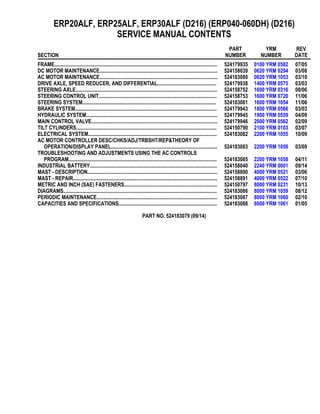
- 1. ERP20ALF, ERP25ALF, ERP30ALF (D216) (ERP040-060DH) (D216) SERVICE MANUAL CONTENTS SECTION PART NUMBER YRM NUMBER REV DATE FRAME............................................................................................................................ 524179935 0100 YRM 0582 07/05 DC MOTOR MAINTENANCE.......................................................................................... 524158039 0620 YRM 0294 03/08 AC MOTOR MAINTENANCE.......................................................................................... 524183080 0620 YRM 1053 03/10 DRIVE AXLE, SPEED REDUCER, AND DIFFERENTIAL............................................. 524179938 1400 YRM 0575 03/03 STEERING AXLE............................................................................................................ 524158752 1600 YRM 0316 08/06 STEERING CONTROL UNIT.......................................................................................... 524158753 1600 YRM 0720 11/06 STEERING SYSTEM...................................................................................................... 524183081 1600 YRM 1054 11/06 BRAKE SYSTEM............................................................................................................ 524179943 1800 YRM 0566 03/03 HYDRAULIC SYSTEM.................................................................................................... 524179945 1900 YRM 0559 04/09 MAIN CONTROL VALVE................................................................................................ 524179946 2000 YRM 0562 02/09 TILT CYLINDERS........................................................................................................... 524150790 2100 YRM 0103 03/07 ELECTRICAL SYSTEM.................................................................................................. 524183082 2200 YRM 1055 10/09 AC MOTOR CONTROLLER DESC/CHKS/ADJ/TRBSHT/REP&THEORY OF OPERATION/DISPLAY PANEL................................................................................. 524183083 2200 YRM 1056 03/09 TROUBLESHOOTING AND ADJUSTMENTS USING THE AC CONTROLS PROGRAM................................................................................................................. 524183085 2200 YRM 1058 04/11 INDUSTRIAL BATTERY................................................................................................. 524158040 2240 YRM 0001 09/14 MAST - DESCRIPTION................................................................................................... 524158890 4000 YRM 0521 03/06 MAST - REPAIR.............................................................................................................. 524158891 4000 YRM 0522 07/10 METRIC AND INCH (SAE) FASTENERS....................................................................... 524150797 8000 YRM 0231 10/13 DIAGRAMS..................................................................................................................... 524183086 8000 YRM 1059 08/12 PERIODIC MAINTENANCE............................................................................................ 524183087 8000 YRM 1060 02/10 CAPACITIES AND SPECIFICATIONS........................................................................... 524183088 8000 YRM 1061 01/05 PART NO. 524183079 (09/14)
- 2. 100 YRM 582 Description General This section has a description and the service procedures for the parts of the frame. These parts include the frame, counterweight assembly, overhead guard, hood and seat assembly, access panels, and label positions. The proce- dure for removing the traction motor is also described in this section. Description MAIN FRAME The main frame is a single weldment. See Figure 1. The main frame has mounts for the following: • Counterweight • Overhead guard, • Battery restraint and hood • Tilt cylinders • Steering axle • Drive axle assembly • Cowl assembly • Floor pedals and floor plates • Side step and fender weldments • Hydraulic tank • Pump and motor assemblies (steer, lift, and traction motors) • Control valves, and the levers The hood is part of the operator and battery restraint system. The seat is part of the operator restraint sys- tem. The floor plates can be removed for access to the traction motor. The panels on the sides of the bat- tery compartment can also be easily removed. The hy- draulic tank, lift pump motor assembly, and the steer- ing pump motor assembly are in a compartment be- tween the battery and the counterweight. The SCR (silicon controlled rectifier) or transistor electronic con- trollers and contactors are in the top of the counter- weight. The top cover of the counterweight can be re- moved for access to the controllers and contactors for early model ERP20-30ALF (B216) lift trucks. See Fig- ure 2. The rear cover of the counterweight can be re- moved for access to the controllers and contactors for later model ERP20-30ALF (B216) trucks and ERP20- 30ALF (ERP040-060DH) (D216) trucks. See Figure 3. There are two main frames for lift trucks made for use in North America and two main frames for lift trucks made for use in Europe. The frames are different because of the different battery compartment sizes. There are two battery compartment lengths. The battery com- partment widths are also different for Europe and North America. See Battery Specifications, at the back of this manual. WARNING The battery must fit the battery compartment so that the battery restraint will operate correctly. A loose battery can cause serious injury and property damage if the lift truck overturns. Adjust the spacer plate to prevent the battery from moving more than 13 mm (0.5 in.) forward or backward. WARNING Maximum clearance between the battery and bat- tery compartment width is 13 mm (0.5 in.). Maxi- mum clearance between the battery and the spacer plate is also 13 mm (0.5 in.). The Battery Specifica- tions chart shows the minimum size compartment allowed. The weight of the battery is a large part of the coun- terweight system on an electric lift truck. Make sure that the battery is within the weight limits indicated on the nameplate. Each model of lift truck has a cast-iron counterweight that provides the additional weight nec- essary for the indicated capacity. OTHER FRAME WELDMENTS These frame parts are the right-hand and left-hand side step and fender weldments, and the cowl weldment. See Figure 1. Each part is a weldment fastened to the main frame to make the frame assembly. The cowl weldment is a mount for the front of the overhead guard (see Figure 2 and Figure 3), the steering column as- sembly (see Figure 4, Figure 5, and Figure 6), the re- lease linkage of the parking brake, and the instrument panel with light switches. The display panels for these models of lift trucks are mounted into the instrument panel. See Figure 4, Figure 5, and Figure 6. 1
- 3. Description 100 YRM 582 1. COWL 2. BATTERY SPACER PLATE 3. BATTERY RETAINER ROD 4. FRAME 5. SIDE STEP AND FENDER WELDMENT 6. ACCESS PANEL 7. FLOOR PLATES Figure 1. Lift Truck Main Frame Legend for Figure 2 1. OVERHEAD GUARD 2. COVER OF ELECTRONICS COMPARTMENT 3. COUNTERWEIGHT 4. TOW PIN AND HANDLE 5. CAPSCREW 6. LOCKWASHER 7. WASHER 8. HANDLE 9. SCREW 10. NUT 11. FOAM TAPE 2
- 4. 100 YRM 582 Description Figure 2. Overhead Guard and Counterweight Early Model ERP20-30ALF (B216) Trucks 3
- 5. Description 100 YRM 582 OVERHEAD GUARD WARNING Do not operate the lift truck without the overhead guard and cowl correctly fastened to the lift truck. The overhead guard is a weldment that fastens to the main frame and cowl to help protect the operator from falling objects. For early model ERP20-30ALF (B216), see Figure 2. For later model ERP20-30ALF (B216) and ERP20-30ALF (ERP040-060DH) (D216) trucks, see Figure 3. A slot in the overhead guard permits removal of the battery without removing the overhead guard. Legend for Figure 3 A. OVERHEAD GUARD USED ON LATER MODEL ERP20-30ALF (B216) TRUCKS B. OVERHEAD GUARD USED ON ERP20-30ALF (ERP040-060DH) (D216) TRUCKS 1. OVERHEAD GUARD 2. HANDLE 3. ROLLING THREAD SCREW 4. NUT 5. WASHER 6. CAPSCREW 7. COVER 8. TOW PIN 9. TAPE 10. COVER 11. SOCKET CAPSCREW 12. LOCKWASHER 13. COUNTERWEIGHT 14. FOAM TAPE 15. SPACER 16. BRACKET 17. SELF RETAINING NUT 4
- 6. 100 YRM 582 Description Figure 3. Overhead Guard and Counterweight Later Model ERP20-30ALF (B216) Trucks and ERP20-30ALF (ERP040-060DH) (D216) Trucks 5
- 7. Description 100 YRM 582 A. CURTIS METER B. GE METER (OPTIONAL) C. STEERING CONTROL UNIT USED ON EARLY MODEL LIFT TRUCKS D. STEERING CONTROL UNIT USED ON LATER MODEL LIFT TRUCKS 1. STEERING WHEEL 2. STEERING CONTROL UNIT 3. LATCH MECHANISM 4. COLUMN COVER 5. COLUMN FRAME 6. HORN SWITCH CONNECTOR 7. ON-DEMAND STEERING COMPONENTS (NOT ALL UNITS) 8. OPTIONAL BASIC DISPLAY PANEL 9. STANDARD DISPLAY PANEL (WITH CURTIS OR GE METER) 10. PREMIUM DISPLAY PANEL 11. HORN BUTTON 12. STEERING COLUMN 13. STEERING COLUMN NUT Figure 4. Steering Column and Instrument Panel Early Model ERP20-30ALF (B216) Lift Trucks 6
- 8. 100 YRM 582 Description 1. STEERING WHEEL 2. SHIFT LEVER MECHANISM 3. COLUMN COVER 4. STEERING CONTROL UNIT 5. COLUMN FRAME 6. ON-DEMAND STEERING COMPONENTS 7. DISPLAY PANEL (PREMIUM DISPLAY PANEL SHOWN) 8. LATCH MECHANISM 9. HORN SWITCH CONNECTOR 10. HORN BUTTON 11. STEERING COLUMN 12. STEERING COLUMN NUT Figure 5. Steering Column and Display Panel, Later Model ERP20-30ALF (B216) Trucks 7
- 9. Description 100 YRM 582 Figure 6. Steering Column and Display Panel, ERP20-30ALF (ERP040-060DH) (D216) Trucks 8
- 10. 100 YRM 582 Description Legend for Figure 6 1. ON-DEMAND STEERING COMPONENTS 2. SHIFT LEVER MECHANISM 3. STEERING WHEEL 4. DISPLAY PANEL 5. COLUMN COVER 6. COLUMN FRAME 7. STEERING CONTROL UNIT 8. COWL WELDMENT 9. DASH 10. COLUMN MOUNT 11. LATCH MECHANISM 12. HORN SWITCH CONNECTOR 13. HORN BUTTON 14. STEERING COLUMN 15. STEERING COLUMN NUT BATTERY AND OPERATOR RESTRAINT, HOOD, AND SEAT ASSEMBLY Battery Restraint WARNING The hood and battery restraint, as well as the latch for the hand lever assembly, must operate correctly before a lift truck is operated. These parts are part of the battery restraint system. The battery restraint system must operate correctly to help provide rea- sonable protection to the operator if the lift truck tips over. A battery restraint system is installed as a safety device. See Figure 7. The function on the battery restraint sys- tem is to hold the battery in the battery compartment in case of a tip over. Part of the battery restraint system is a battery restraint rod at the rear of the battery com- partment. See Figure 7. This restraint rod extends over the rear edge of the battery case to help hold the bat- tery within the battery compartment during a tip over. A handle is used to move the restraint rod. The handle of the battery restraint must be in the DOWN position to close the hood. The handle can be moved to the DOWN position only after the restraint rod is extended over the battery. The restraint rod can only be retracted when the hood is in the UP position. WARNING The battery must fit the battery compartment so that the battery restraint will operate correctly. A loose battery can cause serious injury and property damage if the lift truck overturns. The battery must not be able to move more than 13 mm (0.5 in.) for- ward, backward, or side to side. An adjustable spacer plate is used at the front of the battery compartment to prevent forward and backward movement of the battery. See Figure 8. The adjustable spacer plate is used inside the battery compartment. See Figure 8. The spacer plate must be adjusted for a maximum clearance of 13 mm (0.5 in.) with the bat- tery against the rear bulkhead. There must be some clearance to allow battery removal. See the section Periodic Maintenance 8000 YRM 552 for both early and later model ERP20-30ALF (B216) trucks and Peri- odic Maintenance 8000 YRM 1060, for ERP20-30ALF (ERP040-060DH) (D216) models, to remove the battery and adjust the spacer plate. A. RETRACTED B. EXTENDED 1. BATTERY RESTRAINT WARNING LABEL 2. HOOD 3. BATTERY RESTRAINT HANDLE 4. BATTERY 5. STEEL WELDMENT Figure 7. Battery Restraint Rod 9
- 11. Thank you very much for your reading. Please Click Here. Then Get COMPLETE MANUAL. NO WAITING NOTE: If there is no response to click on the link above, please download the PDF document first and then click on it.
- 12. Description 100 YRM 582 1. BATTERY COMPARTMENT 2. BATTERY 3. BULKHEAD 4. SPACER PLATE 5. ADJUSTMENT CAPSCREW 6. JAM NUTS Figure 8. Battery Spacer Plate Hood WARNING The gas springs for the hood can raise the hood at a rapid rate and cause an injury. DO NOT get over hood when raising hood. WARNING The batteries for these lift trucks must fit the bat- tery compartment width with a maximum of 13 mm (0.5 in.) clearance. The Battery Specifications at the back of this manual, shows the minimum sizes of the battery compartments. Another important part of the battery restraint system is the steel weldment that is also the hood frame. See Figure 7. This hood frame is connected to the lift truck frame with hinges at the rear of the hood (see Fig- ure 13). The front of the hood and frame is locked in the closed position by the assembly for the hydraulic hand levers. A latch releases the assembly to tilt forward and allow the hood to raise. See Figure 9. Gas springs help lift the hood assembly. The seat and other parts of the operator restraint system fasten to the hood assembly. A. CLOSED OVER HOOD B. OPEN 1. HAND LEVER ASSEMBLY 2. HOOD 3. SEAT 4. LATCH HANDLE 5. LATCH Figure 9. Hood and Hand Lever Assembly with Latch 10
- 13. 100 YRM 582 Overhead Guard Replacement Operator Restraint System and Seat Assembly The operator restraint system has the seat, hip re- straints, and the seat belt. The system helps the operator stay within the lift truck in case of a tip over. See Figure 10. Make sure that the seat is not loose on the rails. Make sure the seat rails are not loose. The seat rails must lock securely in position, but move freely when unlocked. The seat rails must be securely attached to the mount- ing surface. Legend for Figure 10 1. SEAT 2. HIP RESTRAINT 3. SEAT BELT AND MOUNT 4. SEAT RAILS 5. CAPSCREW Figure 10. Seat Assembly and Operator Restraint Overhead Guard Replacement REMOVE WARNING Do not weld, drill, grind, or cut the overhead guard for mounts of lights or accessories. The strength of the overhead guard can be reduced. 1. Remove the battery as described in the section Pe- riodic Maintenance 8000 YRM 552 for both early and later ERP20-30ALF (B216) model lift trucks and Periodic Maintenance 8000 YRM 1060 for ERP20-30ALF (ERP040-060DH) (D216) lift truck models. 2. Access to the capscrews that hold the rear legs of the overhead guard to the frame is from the battery compartment. See Figure 11 and Figure 12. Re- move the capscrews, washers, and nuts that fasten each leg. 3. Remove the capscrews, washers, and nuts that hold each front leg of the overhead guard to the cowl. Disconnect any electric wires from under the cowl that go through the front legs of the overhead guard. When the overhead guard is lifted from the frame, make sure these electric wires move through the holes in the frame at the front and rear so that they are not damaged. 4. Use a lifting device or another person to help lift the overhead guard from the lift truck. INSTALL Put the overhead guard on the lift truck. Install any electric wires from the overhead guard legs through the holes in the frame. Install the capscrews, washers, and nuts that hold each front leg to the frame. See Figure 11 and Figure 12. Tighten the capscrews to 102 N•m (75 lbf ft). Install the capscrews, washers, and nuts that hold the rear legs to the frame. Tighten the capscrews to 102 N•m (75 lbf ft). Install the battery as described in the section Periodic Maintenance 8000 YRM 552 for both early and later ERP20-30ALF (B216) model lift trucks and Periodic Maintenance 8000 YRM 1060 for ERP20-30ALF (ERP040-060DH) (D216) lift truck models. 11
- 14. Overhead Guard Replacement 100 YRM 582 Figure 11. Overhead Guard and Counterweight Early Model ERP20-30ALF (B216) Trucks 12