This is the Highly Detailed factory service repair manual for theYALE A908 ERC32AGF (ERC040GH, ERC050GH, ERC060GH, ERC065GH) LIFT TRUCK, this Service Manual has detailed illustrations as well as step by step instructions,It is 100 percents complete and intact. they are specifically written for the do-it-yourself-er as well as the experienced mechanic.YALE A908 ERC32AGF (ERC040GH, ERC050GH, ERC060GH, ERC065GH) LIFT TRUCK Service Repair Workshop Manual provides step-by-step instructions based on the complete dis-assembly of the machine. It is this level of detail, along with hundreds of photos and illustrations, that guide the reader through each service and repair procedure. Complete download comes in pdf format which can work under all PC based windows operating system and Mac also, All pages are printable. Using this repair manual is an inexpensive way to keep your vehicle working properly.
Service Repair Manual Covers:
Frame
Dc motor maintenance
Ac motor repair
Drive axle, speed reducer, and differential
Steering control unit
Steering system
Brake system
Hydraulic system
Main control valve
Main control valve e-controls
Cylinder repair (mast s/n a551, a555, a559, a661, a662, a663, a66, b507,
B508, b509, b551, b555, b559, b562, b563, b564, b661, b662, b663, c515,
C551, c555, c559, d507, d508, d509, d515, d562, d563, d564, e509, and e564)
Electrical system
Ac motor controller desc/chks/adj/trbsht/rep&theory of operation/display panel
Troubleshooting and adjustments using the ac controls program
Industrial battery
Mast - description
Four stage mast
Mast repairs (s/n a551, a555, a559, a661, a662, a663, a664, b507, b508,
B509, b551, b555, b559, b562, b563, b564, b661, b662, b663, c515, c551,
C555, c559, d507, d508, d509, d515, d562, d563, d564, e509, and e564)
Metric and inch (sae) fasteners
Diagrams
Periodic maintenance
File Format: PDF
Compatible: All Versions of Windows & Mac
Language: English
Requirements: Adobe PDF Reader
NO waiting, Buy from responsible seller and get INSTANT DOWNLOAD, Without wasting your hard-owned money on uncertainty or surprise! All pages are is great to haveYALE A908 ERC32AGF (ERC040GH, ERC050GH, ERC060GH, ERC065GH) LIFT TRUCK Service Repair Workshop Manual.
Looking for some other Service Repair Manual,please check:
https://www.aservicemanualpdf.com/
Thanks for visiting!
YALE B216 ERP20-30ALF LIFT TRUCK Service Repair Manualfhjskedmmse
This is the Highly Detailed factory service repair manual for theYALE B216 ERP20-30ALF LIFT TRUCK, this Service Manual has detailed illustrations as well as step by step instructions,It is 100 percents complete and intact. they are specifically written for the do-it-yourself-er as well as the experienced mechanic.YALE B216 ERP20-30ALF LIFT TRUCK Service Repair Workshop Manual provides step-by-step instructions based on the complete dis-assembly of the machine. It is this level of detail, along with hundreds of photos and illustrations, that guide the reader through each service and repair procedure. Complete download comes in pdf format which can work under all PC based windows operating system and Mac also, All pages are printable. Using this repair manual is an inexpensive way to keep your vehicle working properly.
Service Repair Manual Covers:
Frame
Dc motor maintenance
Drive axle, speed reducer, and differential
Steering axle
Steering system
Steering housing and control unit (early models)
Steering control unit
Brake system
Hydraulic system
Main control valve
Tilt cylinders
Instrument cluster
Ev-100zx scr motor controller desc/adj/trbl/repair and theory
Electrical system
Ev-t100 transistor motor controller description, adjustments,troubleshooting, repairs and theory
Ev-100zx scr motor controller parameter tables
Ev-t100 transistor motor controller parameter tables
Troubleshooting and adjustments with a computer
Sr/sp transistor motor controllers description, checks and adjustments, troubleshooting, repairs, and theory of operaton
Display panel for sem controls (dos version)
Sr/sp transistor motor controller parameter tables for fourwheel electric rider lift trucks
Display panel for sem controls
Sr(sem)/sp troubleshooting and adjustments with a computer (windows version)
Industrial battery
Mast - description
Mast - repair
Four stage mast
Metric and inch (sae) fasteners
Periodic maintenance
Capacities and specifications diagrams
Diagrams (sem)
File Format: PDF
Compatible: All Versions of Windows & Mac
Language: English
Requirements: Adobe PDF Reader
NO waiting, Buy from responsible seller and get INSTANT DOWNLOAD, Without wasting your hard-owned money on uncertainty or surprise! All pages are is great to haveYALE B216 ERP20-30ALF LIFT TRUCK Service Repair Workshop Manual.
Looking for some other Service Repair Manual,please check:
https://www.aservicemanualpdf.com/
Thanks for visiting!
Comprehensive program for Agricultural Finance, the Automotive Sector, and Empowerment . We will define the full scope and provide a detailed two-week plan for identifying strategic partners in each area within Limpopo, including target areas.:
1. Agricultural : Supporting Primary and Secondary Agriculture
• Scope: Provide support solutions to enhance agricultural productivity and sustainability.
• Target Areas: Polokwane, Tzaneen, Thohoyandou, Makhado, and Giyani.
2. Automotive Sector: Partnerships with Mechanics and Panel Beater Shops
• Scope: Develop collaborations with automotive service providers to improve service quality and business operations.
• Target Areas: Polokwane, Lephalale, Mokopane, Phalaborwa, and Bela-Bela.
3. Empowerment : Focusing on Women Empowerment
• Scope: Provide business support support and training to women-owned businesses, promoting economic inclusion.
• Target Areas: Polokwane, Thohoyandou, Musina, Burgersfort, and Louis Trichardt.
We will also prioritize Industrial Economic Zone areas and their priorities.
Sign up on https://profilesmes.online/welcome/
To be eligible:
1. You must have a registered business and operate in Limpopo
2. Generate revenue
3. Sectors : Agriculture ( primary and secondary) and Automative
Women and Youth are encouraged to apply even if you don't fall in those sectors.
Symptoms like intermittent starting and key recognition errors signal potential problems with your Mercedes’ EIS. Use diagnostic steps like error code checks and spare key tests. Professional diagnosis and solutions like EIS replacement ensure safe driving. Consult a qualified technician for accurate diagnosis and repair.
What Exactly Is The Common Rail Direct Injection System & How Does It WorkMotor Cars International
Learn about Common Rail Direct Injection (CRDi) - the revolutionary technology that has made diesel engines more efficient. Explore its workings, advantages like enhanced fuel efficiency and increased power output, along with drawbacks such as complexity and higher initial cost. Compare CRDi with traditional diesel engines and discover why it's the preferred choice for modern engines.
𝘼𝙣𝙩𝙞𝙦𝙪𝙚 𝙋𝙡𝙖𝙨𝙩𝙞𝙘 𝙏𝙧𝙖𝙙𝙚𝙧𝙨 𝙞𝙨 𝙫𝙚𝙧𝙮 𝙛𝙖𝙢𝙤𝙪𝙨 𝙛𝙤𝙧 𝙢𝙖𝙣𝙪𝙛𝙖𝙘𝙩𝙪𝙧𝙞𝙣𝙜 𝙩𝙝𝙚𝙞𝙧 𝙥𝙧𝙤𝙙𝙪𝙘𝙩𝙨. 𝙒𝙚 𝙝𝙖𝙫𝙚 𝙖𝙡𝙡 𝙩𝙝𝙚 𝙥𝙡𝙖𝙨𝙩𝙞𝙘 𝙜𝙧𝙖𝙣𝙪𝙡𝙚𝙨 𝙪𝙨𝙚𝙙 𝙞𝙣 𝙖𝙪𝙩𝙤𝙢𝙤𝙩𝙞𝙫𝙚 𝙖𝙣𝙙 𝙖𝙪𝙩𝙤 𝙥𝙖𝙧𝙩𝙨 𝙖𝙣𝙙 𝙖𝙡𝙡 𝙩𝙝𝙚 𝙛𝙖𝙢𝙤𝙪𝙨 𝙘𝙤𝙢𝙥𝙖𝙣𝙞𝙚𝙨 𝙗𝙪𝙮 𝙩𝙝𝙚 𝙜𝙧𝙖𝙣𝙪𝙡𝙚𝙨 𝙛𝙧𝙤𝙢 𝙪𝙨.
Over the 10 years, we have gained a strong foothold in the market due to our range's high quality, competitive prices, and time-lined delivery schedules.
Core technology of Hyundai Motor Group's EV platform 'E-GMP'Hyundai Motor Group
What’s the force behind Hyundai Motor Group's EV performance and quality?
Maximized driving performance and quick charging time through high-density battery pack and fast charging technology and applicable to various vehicle types!
Discover more about Hyundai Motor Group’s EV platform ‘E-GMP’!
What Does the PARKTRONIC Inoperative, See Owner's Manual Message Mean for You...Autohaus Service and Sales
Learn what "PARKTRONIC Inoperative, See Owner's Manual" means for your Mercedes-Benz. This message indicates a malfunction in the parking assistance system, potentially due to sensor issues or electrical faults. Prompt attention is crucial to ensure safety and functionality. Follow steps outlined for diagnosis and repair in the owner's manual.
In this presentation, we have discussed a very important feature of BMW X5 cars… the Comfort Access. Things that can significantly limit its functionality. And things that you can try to restore the functionality of such a convenient feature of your vehicle.
"Trans Failsafe Prog" on your BMW X5 indicates potential transmission issues requiring immediate action. This safety feature activates in response to abnormalities like low fluid levels, leaks, faulty sensors, electrical or mechanical failures, and overheating.
Why Is Your BMW X3 Hood Not Responding To Release CommandsDart Auto
Experiencing difficulty opening your BMW X3's hood? This guide explores potential issues like mechanical obstruction, hood release mechanism failure, electrical problems, and emergency release malfunctions. Troubleshooting tips include basic checks, clearing obstructions, applying pressure, and using the emergency release.
Fleet management these days is next to impossible without connected vehicle solutions. Why? Well, fleet trackers and accompanying connected vehicle management solutions tend to offer quite a few hard-to-ignore benefits to fleet managers and businesses alike. Let’s check them out!
5 Warning Signs Your BMW's Intelligent Battery Sensor Needs AttentionBertini's German Motors
IBS monitors and manages your BMW’s battery performance. If it malfunctions, you will have to deal with an array of electrical issues in your vehicle. Recognize warning signs like dimming headlights, frequent battery replacements, and electrical malfunctions to address potential IBS issues promptly.
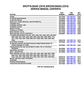
1. ERC/P16-20AAF (C814) (ERC030-040AH) (C814)
SERVICE MANUAL CONTENTS
SECTION
PART
NUMBER
YRM
NUMBER
REV
DATE
FRAME............................................................................................................................ 524179936 0100 YRM 0617 03/06
DC MOTOR MAINTENANCE.......................................................................................... 524158039 0620 YRM 0294 03/08
AC MOTOR REPAIR...................................................................................................... 524205680 0620 YRM 1098 03/10
DRIVE AXLE, SPEED REDUCER, AND DIFFERENTIAL............................................. 524179939 1400 YRM 0618 03/06
STEERING AXLE............................................................................................................ 524179940 1600 YRM 0619 03/06
STEERING CONTROL UNIT.......................................................................................... 524158753 1600 YRM 0720 11/06
STEERING SYSTEM...................................................................................................... 524183081 1600 YRM 1054 11/06
BRAKE SYSTEM............................................................................................................ 524179944 1800 YRM 0620 03/08
HYDRAULIC SYSTEM.................................................................................................... 524179945 1900 YRM 0559 04/09
MAIN CONTROL VALVE................................................................................................ 524179946 2000 YRM 0562 02/09
MAIN CONTROL VALVE E-CONTROLS....................................................................... 524256687 2000 YRM 1224 04/08
CYLINDER REPAIR (MAST S/N A551, A555, A559, A661, A662, A663, A66, B507,
B508, B509, B551, B555, B559, B562, B563, B564, B661, B662, B663, C515,
C551, C555, C559, D507, D508, D509, D515, D562, D563, D564, E509, AND
E564).......................................................................................................................... 524223768 2100 YRM 1139 02/14
ELECTRICAL SYSTEM.................................................................................................. 524183082 2200 YRM 1055 10/09
AC MOTOR CONTROLLER DESC/CHKS/ADJ/TRBSHT/REP&THEORY OF
OPERATION/DISPLAY PANEL................................................................................. 524183083 2200 YRM 1056 03/09
TROUBLESHOOTING AND ADJUSTMENTS USING THE AC CONTROLS
PROGRAM................................................................................................................. 524183085 2200 YRM 1058 04/11
INDUSTRIAL BATTERY................................................................................................. 524158040 2240 YRM 0001 09/14
MAST - DESCRIPTION................................................................................................... 524158890 4000 YRM 0521 03/06
MAST REPAIRS (S/N A551, A555, A559, A661, A662, A663, A664, B507, B508,
B509, B551, B555, B559, B562, B563, B564, B661, B662, B663, C515, C551,
C555, C559, D507, D508, D509, D515, D562, D563, D564, E509, AND E564)........ 524223776 4000 YRM 1148 02/14
METRIC AND INCH (SAE) FASTENERS....................................................................... 524150797 8000 YRM 0231 10/13
DIAGRAMS..................................................................................................................... 524183086 8000 YRM 1059 08/12
PERIODIC MAINTENANCE............................................................................................ 524183087 8000 YRM 1060 02/10
CAPACITIES AND SPECIFICATIONS........................................................................... 524213865 8000 YRM 1113 11/06
PART NO. 524262629 (09/14)
2. 100 YRM 617 Description
General
This section has a description and the service procedures for the parts of the frame. These parts include the frame,
counterweight assembly, overhead guard, hood and seat assembly, access panels, and label positions. The proce-
dure for removing the traction motor is also described in this section.
Description
MAIN FRAME
The main frame is a single weldment. See Figure 1,
Figure 2 and Figure 3. The main frame has mounts for
the following:
• Counterweight
• Overhead guard
• Battery restraint and hood
• Seat plate (with optional seat brake)
• Tilt cylinders
• Steering axle
• Drive axle assembly
• Cowl assembly
• Floor pedals and floor plates
• Side step and fender weldments
• Hydraulic tank, pump, and motor assembly
• Control valves and levers
The hood is part of the operator and battery restraint
system. The seat is also part of the operator restraint
system. The floor plates can be removed for access
to the traction motor. A panel in the bottom of the bat-
tery compartment can be removed for access to the hy-
draulic pump motor and the steering pump motor. The
electronic controller and contactors are attached to the
lift truck frame and surrounded by the counterweight. A
panel in the counterweight can be removed for access
to the controller and contactors.
WARNING
The battery must fit the battery compartment so
that the battery restraint will operate correctly. A
loose battery can cause serious injury and property
damage if the lift truck overturns. Adjust the spac-
ers to prevent the battery from moving more than
13 mm (0.5 in.) in any horizontal direction. See Fig-
ure 4.
WARNING
Maximum clearance between the battery and bat-
tery compartment width is 13 mm (0.5 in.). Maxi-
mum clearance between the battery and the spacer
plate is also 13 mm (0.5 in.). The Battery Specifica-
tions chart shows the minimum size compartment
allowed.
The weight of the battery is a large part of the coun-
terweight system on an electric lift truck. Make sure
that the battery is within the weight limits indicated on
the nameplate. Each model of lift truck has a cast-iron
counterweight that provides the additional weight nec-
essary for the indicated capacity. A slot in the overhead
guard permits removal of the battery without removing
the overhead guard.
Figure 5, Figure 6, and Figure 7 shows covers for in-
strument panel and control valve.
1
12. 100 YRM 617 Description
Legend for Figure 7
1. MOUNTING PANEL
2. DASH
3. NUT (FOLDOVER)
4. CAPSCREW
5. LINER
6. WASHER
7. LOCKWASHER
8. NUT
9. CATCH
10. PLATE
11. COVER
12. PLATE
13. COVER
OTHER FRAME WELDMENTS
These frame parts are the right-hand and left-hand side
step and fender weldments and the cowl weldment (see
Figure 1 and Figure 2.) Each part is a weldment fas-
tened to the main frame to make the frame assembly.
The cowl weldment is a mount for the front of the over-
head guard, the steering column assembly, the release
linkage of the parking brake and the instrument panel
with light switches. The display panel is on the right side
of the steering column and attached to the instrument
panel for lift truck models with SEM (Separately Excited
Motor), SCR (Silicon Controlled Rectifier), Alternating
Current (AC) and electronic controllers and contactors.
See Figure 5, Figure 8, Figure 9, Figure 10, Figure 11,
and Figure 12.
A. STANDARD SEM DISPLAY PANEL B. PREMIUM SEM DISPLAY PANEL
Figure 8. SEM Display Panel
11
13. Description 100 YRM 617
NOTE: FOR LIFT TRUCKS MODELS WITH AC ELECTRONIC CONTROLLERS AND CONTACTORS, BOTH THE
STANDARD AND PREMIUM DISPLAY PANELS LOOK IDENTICAL. THE ONLY DIFFERENCE IS IN THE DISPLAY
SOFTWARE AND THE RESULTING FUNCTIONALITY.
Figure 9. AC Display Panel
OVERHEAD GUARD
WARNING
Do not operate the lift truck without the overhead
guard correctly fastened to the lift truck.
The overhead guard is a weldment that fastens to the
main frame and cowl to help protect the operator from
falling objects. See Figure 10, Figure 11, and Figure 12.
Legend for Figure 10
NOTE: THE DISPLAY PANELS SHOWN ARE FOR LIFT TRUCKS WITH SCR ELECTRONIC CONTROLLERS AND
CONTACTORS.
A. STEERING CONTROL UNIT USED ON EARLY MODEL LIFT TRUCKS
B. STEERING CONTROL UNIT USED ON LATER MODEL LIFT TRUCKS
1. OVERHEAD GUARD
2. STEERING WHEEL
3. ON-DEMAND STEERING COMPONENTS (NOT
ALL UNITS)
4. HORN SWITCH CONNECTOR
5. COLUMN COVER
6. COLUMN FRAME
7. STEERING CONTROL UNIT
8. LATCH MECHANISM
9. OPTIONAL PREMIUM DISPLAY PANEL
10. OPTIONAL BASIC DISPLAY PANEL
11. REGULAR DISPLAY PANEL*
12. HORN BUTTON
13. STEERING COLUMN
14. STEERING COLUMN NUT
*CURTIS METER SHOWN. PANEL AVAILABLE WITH OPTIONAL GENERAL ELECTRIC METER.
12
15. Thank you very much for
your reading. Please Click
Here. Then Get COMPLETE
MANUAL. NO WAITING
NOTE:
If there is no response to
click on the link above,
please download the PDF
document first and then
click on it.
19. 100 YRM 617 Overhead Guard Replacement
Legend for Figure 12
NOTE: DISPLAY PANELS SHOWN ARE FOR LIFT TRUCKS WITH AC ELECTRIC CONTROLLERS AND CON-
TACTORS.
NOTE: OVERHEAD GUARD FOR LIFT TRUCK MODELS ERC030, 040AH (B814/C814) SHOWN. SEE FIGURE 13
FOR OVERHEAD GUARD USED ON ERC/P16-20AAF (B814/C814) LIFT TRUCKS.
1. ON-DEMAND STEERING COMPONENTS
2. SHIFT LEVER MECHANISM
3. STEERING WHEEL
4. DISPLAY PANEL
5. COLUMN COVER
6. COLUMN FRAME
7. STEERING CONTROL UNIT
8. COWL WELDMENT
9. DASH
10. COLUMN MOUNT
11. OVERHEAD GUARD
12. LATCH MECHANISM
13. CAPSCREW
14. WASHER
15. NUT
16. SCREW
17. OVERHEAD GUARD HANDLE
18. HORN SWITCH CONNECTOR
19. HORN BUTTON
20. STEERING COLUMN
21. STEERING COLUMN NUT
Overhead Guard Replacement
REMOVE
WARNING
Do not weld, drill, grind, or cut the overhead guard
for mounts for lights or accessories. The strength
of the overhead guard can be reduced.
1. Remove the battery as described in the section
Periodic Maintenance 8000 YRM 552 for lift
truck models ERC/P16-20AAF (ERC030-40AF,
AG/BG) (A814), and Periodic Maintenance 8000
YRM 1060 for lift truck models ERC/P16-20AAF
(ERC030, 040AH) (B814/C814), or your vehicle’s
Operating Manual.
2. Access to the capscrews that hold the rear legs of
the overhead guard to the frame is from the battery
compartment. Remove the, capscrews, washers,
and nuts that fasten each leg. See Figure 10, Fig-
ure 11, Figure 12, Figure 13, and Figure 14.
3. Remove the capscrews, washers, and nuts that
hold each front leg of the overhead guard to the
cowl. Disconnect any electric wires from under the
cowl that go through the front legs of the overhead
guard. When the overhead guard is lifted from the
frame, make sure these electric wires move through
the holes in the frame at the front and rear so that
they are not damaged.
4. Use a lifting device or another person to help lift the
overhead guard from the lift truck.
1. CAPSCREW
2. WASHER
3. NUT
4. OVERHEAD GUARD HANDLE
5. OVERHEAD GUARD
Figure 13. Overhead Guard, Lift Truck Models
ERC/P16-20AAF (ERC030, 040AH) (B814/C814)
17