SlideShare a Scribd company logo
1 of 19
Download to read offline
ERC20AGF, ERC25AGF, ERC30AGF, ERC32AGF (ERC040GH, ERC050GH,
ERC060GH, ERC065GH) (A908)
SERVICE MANUAL CONTENTS
SECTION
PART
NUMBER
YRM
NUMBER
REV
DATE
FRAME............................................................................................................................ 524179934 0100 YRM 0558 11/07
DC MOTOR MAINTENANCE.......................................................................................... 524158039 0620 YRM 0294 03/08
AC MOTOR REPAIR...................................................................................................... 524205680 0620 YRM 1098 03/10
DRIVE AXLE, SPEED REDUCER, AND DIFFERENTIAL............................................. 524179937 1400 YRM 0285 06/10
STEERING AXLE............................................................................................................ 524158906 1600 YRM 0258 11/06
STEERING CONTROL UNIT.......................................................................................... 524158753 1600 YRM 0720 11/06
STEERING SYSTEM...................................................................................................... 524183081 1600 YRM 1054 11/06
BRAKE SYSTEM............................................................................................................ 524179942 1800 YRM 0574 04/08
HYDRAULIC SYSTEM.................................................................................................... 524179945 1900 YRM 0559 04/09
MAIN CONTROL VALVE................................................................................................ 524179946 2000 YRM 0562 02/09
MAIN CONTROL VALVE E-CONTROLS....................................................................... 524256687 2000 YRM 1224 04/08
CYLINDER REPAIR (MAST S/N A551, A555, A559, A661, A662, A663, A66, B507,
B508, B509, B551, B555, B559, B562, B563, B564, B661, B662, B663, C515,
C551, C555, C559, D507, D508, D509, D515, D562, D563, D564, E509, AND
E564).......................................................................................................................... 524223768 2100 YRM 1139 02/14
ELECTRICAL SYSTEM.................................................................................................. 524183082 2200 YRM 1055 10/09
AC MOTOR CONTROLLER DESC/CHKS/ADJ/TRBSHT/REP&THEORY OF
OPERATION/DISPLAY PANEL................................................................................. 524183083 2200 YRM 1056 03/09
TROUBLESHOOTING AND ADJUSTMENTS USING THE AC CONTROLS
PROGRAM................................................................................................................. 524183085 2200 YRM 1058 04/11
INDUSTRIAL BATTERY................................................................................................. 524158040 2240 YRM 0001 09/14
MAST - DESCRIPTION................................................................................................... 524158890 4000 YRM 0521 03/06
FOUR STAGE MAST...................................................................................................... 524179953 4000 YRM 0563 04/05
MAST REPAIRS (S/N A551, A555, A559, A661, A662, A663, A664, B507, B508,
B509, B551, B555, B559, B562, B563, B564, B661, B662, B663, C515, C551,
C555, C559, D507, D508, D509, D515, D562, D563, D564, E509, AND E564)........ 524223776 4000 YRM 1148 02/14
METRIC AND INCH (SAE) FASTENERS....................................................................... 524150797 8000 YRM 0231 10/13
DIAGRAMS..................................................................................................................... 524183086 8000 YRM 1059 08/12
PERIODIC MAINTENANCE............................................................................................ 524183087 8000 YRM 1060 02/10
CAPACITIES AND SPECIFICATIONS........................................................................... 524204007 8000 YRM 1083 11/06
PART NO. 524201427 (09/14)
100 YRM 558 Description
General
This section has a description and the service procedures for the parts of the frame. These parts include the frame,
counterweight assembly, overhead guard, hood and seat assembly, access panels, and label positions. The proce-
dure for removing the traction motor is also described in this section.
Description
MAIN FRAME
The main frame is a single weldment. See Figure 1.
The main frame has mounts for the following:
• Counterweight
• Overhead guard
• Battery restraint and hood
• Seat plate (with optional seat brake)
• Tilt cylinders
• Steering axle
• Drive axle assembly
• Cowl assembly
• Floor pedals and floor plates
• Side step and fender weldments
• Hydraulic tank
• Pump and motor assemblies (steer, lift, and traction
motors)
• Control valves and levers
The hood is part of the operator and battery restraint
system. The seat is also part of the operator restraint
system. The floor plates are removed for access to the
steering motor. A panel in the bottom of the battery
compartment is removed for access to the traction mo-
tor and the hydraulic pump motor. The electronic con-
troller and contactors are attached to the frame. A panel
in the counterweight is removed for access to the con-
troller and contactors. See Figure 16. For the location
of the Master Controller and Electro-Hydraulics Valve
Driver Module, see the section Electro-hydraulic Con-
trol Valve 2000 YRM 1224.
WARNING
The battery must fit the battery compartment so
that the battery restraint will operate correctly. A
loose battery can cause serious injury and property
damage if the lift truck overturns. Adjust the spacer
plate to prevent the battery from moving more than
13 mm (0.5 in.) forward or backward.
The lift trucks are equipped with an adjustable spacer
plate in the battery compartment. See Figure 2. Adjust
the spacer plate to control the movement of the battery
in the forward and backward directions. Tighten the jam
nuts on the adjustment capscrew to prevent the adjust-
ment from changing.
WARNING
Maximum clearance between the battery and bat-
tery compartment width is 13 mm (0.5 in.). Maxi-
mum clearance between the battery and the spacer
plate is also 13 mm (0.5 in.). The Battery Specifica-
tions chart shows the minimum size compartment
allowed.
The weight of the battery is a large part of the coun-
terweight system on an electric lift truck. Make sure
that the battery is within the weight limits indicated on
the Nameplate. Each model of lift truck has a cast-iron
counterweight that provides the additional weight nec-
essary for the indicated capacity. A slot in the overhead
guard permits removal of the battery without removing
the overhead guard.
1
Description 100 YRM 558
Figure 1. Lift Truck Frame
2
100 YRM 558 Description
Legend for Figure 1
NOTE: OPTIONAL SIDE PANELS FOR BATTERY COMPARTMENT NOT SHOWN.
1. COWL
2. BATTERY COMPARTMENT ACCESS COVERS
3. BATTERY SPACER PLATE*
4. BATTERY SPACER PLATE**
5. SIDE STEP AND FENDER WELDMENT
6. FRAME
7. FLOOR MATS
8. FLOOR PLATES (COVERS)
* BATTERY SPACER PLATE USED ON NEWER LIFT TRUCK MODELS
** BATTERY SPACER PLATE USED ON OLDER LIFT TRUCK MODELS
1. BATTERY
COMPARTMENT
2. BATTERY
3. BULKHEAD
4. SPACER PLATE
5. ADJUSTMENT
CAPSCREW
6. JAM NUTS
Figure 2. Battery Spacer Plate
OTHER FRAME WELDMENTS
These frame parts are the right-hand and left-hand
side step and fender weldments and the cowl weld-
ment. See Figure 1. Each part is a weldment fastened
to the main frame to make the frame assembly. The
cowl weldment is a mount for the front of the overhead
guard, the steering column assembly, the release
linkage of the parking brake, and the instrument panel
with light switches. The display panel is on the right
side of the steering column and attached to the instru-
ment panel for lift truck models with SEM (Separately
Excited Motor), SCR (Silicon Controlled Rectifier), and
AC (Alternating Current) electronic controllers and
contactors. See Figure 3, Figure 4, Figure 5, Figure 6,
and Figure 7.
OVERHEAD GUARD
WARNING
Do not operate the lift truck without the overhead
guard correctly fastened to the lift truck.
The overhead guard is a weldment that fastens to the
main frame and cowl to help protect the operator from
falling objects. See Figure 5, Figure 6, Figure 7, or
Figure 9.
3
Description 100 YRM 558
A. STANDARD SEM DISPLAY PANEL B. PREMIUM SEM DISPLAY PANEL
Figure 3. SEM Display Panel
NOTE: FOR LIFT TRUCK MODELS WITH AC ELECTRONIC CONTROLLERS AND CONTACTORS, BOTH THE
STANDARD AND PREMIUM DISPLAY PANELS LOOK IDENTICAL. THE ONLY DIFFERENCE IS IN THE DISPLAY
SOFTWARE AND THE RESULTING FUNCTIONALITY.
Figure 4. AC Display Panel
4
100 YRM 558 Overhead Guard Replacement
Overhead Guard Replacement
REMOVE
WARNING
Do not weld, drill, grind, or cut the overhead guard
for mounts, lights, or accessories. The strength of
the overhead guard can be reduced.
1. Remove the battery from the truck. See How to
Change Battery in your vehicle’s Periodic Main-
tenance or Operating Manual.
2. Access to the capscrews that hold the rear legs of
the overhead guard to the frame is from the bat-
tery compartment. Remove the capscrews, wash-
ers, and nuts that fasten each leg. See Figure 5,
Figure 6, Figure 7, Figure 8, and Figure 9.
3. Remove the capscrews, washers, and nuts that
hold each front leg of the overhead guard to the
cowl. Disconnect any electric wires from under the
cowl that go through the front legs of the overhead
guard. When the overhead guard is lifted from the
frame, make sure these electric wires move through
the holes in the frame at the front and rear so that
they are not damaged.
4. Use a lifting device or another person to help lift the
overhead guard from the lift truck.
INSTALL
Put the overhead guard on the lift truck. Install any
electric wires from the overhead guard legs through
the holes in the frame. Install the capscrews, wash-
ers, and nuts that hold each front leg to the frame.
Tighten capscrews to 55 N•m (41 lbf ft). Install the
capscrews, washers, and nuts that hold the rear legs
to the frame. For lift truck models ERC20-30AGF
(ERC040-065RF/ZF, ERC040-065RG/ZG) (E108),
tighten the capscrews to 68 N•m (50 lbf ft). For lift truck
models ERC20-30AGF (ERC040-065GH) (A908),
tighten the capscrews to 90 N•m (66 lbf ft). Install the
battery. See How to Change Battery in your vehicle’s
Periodic Maintenance or Operating Manual.
5
Overhead Guard Replacement 100 YRM 558
Figure 5. Overhead Guard, Steering Column, and Display Panel, Truck Models ERC20-30AGF
(ERC040-065RF/ZF) (E108)
6
100 YRM 558 Overhead Guard Replacement
Legend for Figure 5
NOTE: DISPLAY PANELS SHOWN ARE FOR LIFT TRUCKS WITH SCR ELECTRONIC CONTROLLERS AND
CONTACTORS.
A. STEERING CONTROL UNIT USED ON EARLY MODEL LIFT TRUCKS
B. STEERING CONTROL UNIT USED ON LATER MODEL LIFT TRUCKS
1. OVERHEAD GUARD
2. STEERING WHEEL
3. ON-DEMAND STEERING COMPONENTS (NOT
ALL UNITS)
4. HORN SWITCH CONNECTOR
5. COLUMN COVER
6. COLUMN FRAME
7. STEERING CONTROL UNIT
8. LATCH MECHANISM
9. OPTIONAL PREMIUM DISPLAY PANEL
10. REGULAR DISPLAY PANEL*
11. CAPSCREW
12. WASHER
13. NUT
14. SCREW
15. OVERHEAD GUARD HANDLE
16. HORN SWITCH CONNECTOR
17. STEERING COLUMN
18. STEERING COLUMN NUT
*CURTIS METER SHOWN. PANEL AVAILABLE WITH OPTIONAL GENERAL ELECTRIC™ METER.
7
Overhead Guard Replacement 100 YRM 558
Figure 6. Overhead Guard, Steering Column, and Display Panel, Truck Models ERC20-30AGF
(ERC040-065RG/ZG) (E108)
8
100 YRM 558 Overhead Guard Replacement
Legend for Figure 6
NOTE: DISPLAY PANELS SHOWN ARE FOR LIFT TRUCKS WITH SEM ELECTRONIC CONTROLLERS AND
CONTACTORS.
1. STEERING WHEEL
2. SHIFT LEVER MECHANISM
3. COLUMN COVER
4. LATCH MECHANISM
5. STEERING CONTROL UNIT
6. COLUMN FRAME
7. ON-DEMAND STEERING COMPONENTS
8. DISPLAY PANEL (PREMIUM DISPLAY PANEL
SHOWN)
9. OVERHEAD GUARD
10. CAPSCREW
11. WASHER
12. NUT
13. SCREW
14. OVERHEAD GUARD HANDLE
15. HORN SWITCH CONNECTOR
16. HORN BUTTON
17. STEERING COLUMN
18. STEERING COLUMN NUT
9
Thank you very much for
your reading. Please Click
Here. Then Get COMPLETE
MANUAL. NO WAITING
NOTE:
If there is no response to
click on the link above,
please download the PDF
document first and then
click on it.
Overhead Guard Replacement 100 YRM 558
Figure 7. Overhead Guard, Steering Column, and Display Panel, Truck Models ERC20-30AGF
(ERC040-065GH) (A908)
10
100 YRM 558 Overhead Guard Replacement
Legend for Figure 7
NOTE: DISPLAY PANELS SHOWN ARE FOR LIFT TRUCKS WITH AC ELECTRONIC CONTROLLERS AND CON-
TACTORS.
NOTE: OVERHEAD GUARD FOR LIFT TRUCK MODELS ERC040-065GH (A908) SHOWN. SEE FIGURE 8 FOR
OVERHEAD GUARD USED ON ERC20-30AGF (A908) MODELS.
1. ON-DEMAND STEERING COMPONENTS
2. SHIFT LEVER MECHANISM
3. STEERING WHEEL
4. DISPLAY PANEL
5. COLUMN COVER
6. COLUMN FRAME
7. STEERING CONTROL UNIT
8. COWL WELDMENT
9. DASH
10. COLUMN MOUNT
11. OVERHEAD GUARD
12. LATCH MECHANISM
13. CAPSCREW
14. WASHER
15. NUT
16. SCREW
17. OVERHEAD GUARD HANDLE
18. HORN SWITCH CONNECTOR
19. HORN BUTTON
20. STEERING COLUMN
21. STEERING COLUMN NUT
Figure 8. Overhead Guard, Lift Truck Models
ERC20-30AGF (A908)
Legend for Figure 8
1. OVERHEAD GUARD
2. PLUG
3. NUT
4. LOCKWASHER
5. CAPSCREW
6. WASHER
7. HANDLE
8. SCREW
11
Battery and Operator Restraint System, Hood and Seat Brake, and Seat Assembly Replacement 100 YRM 558
1. FRONT LEG, OVERHEAD GUARD
2. SETSCREW
3. ATTACHMENT PLATE
4. REAR LEG, OVERHEAD GUARD
5. COUNTERWEIGHT
6. TOW PIN
7. BOLT
Figure 9. Overhead Guard and Counterweight
Battery and Operator Restraint System, Hood and Seat
Brake, and Seat Assembly Replacement
BATTERY RESTRAINT SYSTEM
WARNING
On units with a shorter frame, the gas spring for the
hood can raise the hood at a rapid rate and cause an
injury. Do NOT bend over hood when raising hood.
A battery restraint system is installed as a safety de-
vice. See Figure 10. The function of the battery re-
straint system, when correctly locked in the down posi-
tion, is to hold the battery in the battery compartment
if an accident causes the lift truck to tip over. The bat-
tery restraint is a steel weldment that is connected to the
frame with a hinge. A sliding latch mechanism (see Fig-
ure 10.) locks the battery restraint in the down position
for operation. The latch, at the top center of the coun-
terweight, unlocks the battery restraint from the frame,
so that the battery restraint can be raised to the up po-
sition for access to the battery. The battery restraint is
also the support for the hood. A gas spring helps lift
the hood assembly. A rod is used to hold the hood in
the up position on units with a longer frame. The oper-
ator must hold the hood assembly with one hand. Use
the other hand to move the rod to the storage position.
Lower the hood and battery restraint assembly to the
operating position. Make sure that the battery restraint
is correctly locked to the frame for operation of the lift
truck.
12
100 YRM 558 Battery and Operator Restraint System, Hood and Seat Brake, and Seat Assembly Replacement
1. HOOD
2. SEAT
3. LATCH ASSEMBLY
4. BATTERY RESTRAINT AND HOOD FRAME
5. GAS SPRING
6. HINGE
7. STOP ROD
8. RELEASE LABEL FOR STOP ROD
9. COUNTERWEIGHT
10. LATCH HANDLE
11. LIFT HANDLE
12. LATCH WARNING LABEL
Figure 10. Hood, Latch, and Battery Restraint System
WARNING
Correct operation of the battery restraint system re-
quires that the battery does not move more than
13 mm (0.5 in.) horizontally. Make sure that the bat-
tery spacer plate is correctly adjusted.
WARNING
The battery restraint and its latch mechanisms must
operate correctly before a lift truck is operated.
To operate correctly, the battery restraint must be locked
in the down position. The battery compartment has an
adjustable spacer plate, which is used to prevent for-
ward and backward movement of the battery. Adjust the
spacer plate to prevent movement in any one horizontal
direction of 13 mm (0.5 in.) maximum. See Figure 2.
Raise the seat. Use the knob for the latch to release the
battery restraint. See Figure 10. Use the handle on the
hood to raise the battery restraint and hood. Make sure
that the battery cannot move more than a total of 13 mm
(0.5 in.) in any one horizontal direction. Make sure the
spacer plate is correctly adjusted to prevent movement.
Push the hood and the battery restraint down until the
latch locks. Make sure the battery restraint is locked se-
curely. Lift on the handle to make sure it is latched and
will not move.
HOOD
The hood must be locked in the down position dur-
ing operation. The battery must have the spacer
plate correctly adjusted to prevent forward or back-
ward movement of 13 mm (0.5 in.) maximum.
On lift trucks ERC20-30AGF (ERC40-065RF/ZF,
ERC40-065RG/ZG) (E108), if the unit has a seat
brake, raise the seat and seat plate assembly. Use the
latch handle at the rear of the hood (see Figure 11) to
release the hood frame and battery restraint. Raise the
latch handle and slide the handle toward the right side
of the truck. A spring moves the handle back to the left.
Use the lift handle by the seat to raise the hood. See
Figure 11. A gas spring and stop rod will hold the as-
sembly in the up position. Make sure that the battery
cannot move more than a total of 13 mm (0.5 in.) in any
one horizontal direction. If necessary, adjust the battery
spacer plate as shown in Figure 2.
13
Battery and Operator Restraint System, Hood and Seat Brake, and Seat Assembly Replacement 100 YRM 558
1. HINGE
2. LIFT HANDLE
3. HOOD
4. LATCH HANDLE
5. SEAT BRAKE
PLATE
Figure 11. Hood and Seat Brake Plate Assembly,
Lift Truck Models ERC20-30AGF (ERC40-065RF/ZF,
ERC40-065RG/ZG) (E108)
Release the stop rod by moving it to the right before low-
ering hood. See the label in Figure 10. Make sure the
latch handle is fully to the right when closing the hood
so that the latch can engage the latch piece. Make sure
the hood is locked securely. Try to raise the hood using
only the lift handle to make sure the hood is latched and
will not move.
HOOD WITH E-HYDRAULICS
WARNING
The gas spring for the hood can raise the hood at
a rapid rate and cause an injury. DO NOT lean over
hood when raising hood.
WARNING
The batteries for these lift trucks must fit the battery
compartment width with a maximum of 13 mm (0.5
in.) clearance. The Battery Specifications, at the
back of this manual, shows the minimum sizes of
the battery compartment.
Another important part of the battery restraint system
is the steel weldment that is also the hood frame. This
hood frame is connected to the lift truck frame with
hinges at the rear of the hood. Gas springs help lift the
hood assembly. The seat and other parts of the opera-
tor restraint system fasten to the hood assembly.
NOTE: Before raising the hood, move the steering col-
umn to the forward position and slide the seat all the
way back, and If necessary, move the armrest all the
way back. See Figure 12.
1. ARMREST ADJUSTMENT HANDLE
Figure 12. Armrest Latch Location
The latch that secures the cover for the hood release
handle can be either a locking or non locking latch. If
the latch is a locking latch, unlock latch with key first.
The cover, latch and hood release handle are located
on the right side of the hood. See Figure 13.
Pull the latch handle, located on the top of the latch, to
the up position and then pull on latch handle to move
cover away from hood release handle. Pull hood re-
lease handle up to release hood latch mechanism. See
Figure 13. Use handle on the hood to place hood in the
raised position.
14
100 YRM 558 Battery and Operator Restraint System, Hood and Seat Brake, and Seat Assembly Replacement
Before lowering the hood, make sure the battery re-
straint rod is over the battery. Lower the hood and push
hood release handle down to secure hood to frame.
Move cover over hood release handle and push latch
handle down to secure cover to hood. If latch is a lock-
ing latch, lock latch with key.
1. LATCH
2. COVER
3. HOOD RELEASE
HANDLE
4. HOOD LATCH
MECHANISM
5. COMPRESSION
SPRING
6. PIN
7. SCREW
8. CAPSCREW
9. NUT
10. LOCKWASHER
11. WASHER
12. LATCH HANDLE
Figure 13. Latch and Cover With E-Hydraulics
SEAT BRAKE
On ERC20-30AGF (ERC40-065RF/ZF, ERC40-065RG/
ZG) (E108) units with a seat brake, there is a separate
plate with a hinge fastened to the front of the battery
compartment (see Figure 11.) The seat is fastened to
this plate instead of the hood on these units. The link-
age for the seat plate has a spring that holds the plate
up and applies the brake on the rear of the traction mo-
tor. During operation of the lift truck, the seat brake will
be applied to the traction motor if the seat brake switch,
located under the seat, senses that the operator has
left the seat and the parking brake has not been ap-
plied. On these units, push the seat and seat plate into
position over the hood. See Figure 11 and Figure 14.
OPERATOR RESTRAINT SYSTEM AND
SEAT ASSEMBLY
The seat belt, hip restraint brackets, seat and mounting,
hood, and latches are all part of the operator restraint
system. Each item must be checked to make sure it
is attached securely, functions correctly, and is in good
condition. See Figure 14.
Automatic Locking Retractor (ALR)
NOTE: ERC20-30AGF (ERC40-065RF/ZF, ERC40-
065RG/ZG) (E108) lift trucks produced before Novem-
ber 2005 are equipped with the ALR type seat belts.
The seat belt must fasten securely. Make sure the seat
belt extends and retracts smoothly and is not frayed or
torn. If the seat belt is damaged or does not operate
properly, it must be replaced. See Figure 14.
1. SEAT
2. HIP RESTRAINT
3. SEAT BELT AND
MOUNT
4. HOOD
5. SEAT RAILS
6. SEAT PLATE (WITH
SEAT BRAKE)*
*THE SEAT PLATE IS NOT USED ON ERC20-30AGF
(ERC040-065GH) (A908) TRUCKS.
Figure 14. Operator Restraint and Seat Assembly
15
Battery and Operator Restraint System, Hood and Seat Brake, and Seat Assembly Replacement 100 YRM 558
Emergency Locking Retractor (ELR)
NOTE: Lift trucks produced after November 2005 are
equipped with the Emergency Locking Retractor (ELR)
style seat belt.
When the ELR style seat belt is properly buckled across
the operator, the belt will permit slight operator reposi-
tioning without activating the locking mechanism. If the
truck tips, travels off a dock, or comes to a sudden stop,
the locking mechanism will be activated and hold the
operator’s lower torso in the seat.
A seat belt that is damaged worn or does not operate
properly will not give protection when it is needed. The
end of the belt must fasten correctly in the latch. The
seat belt must be in good condition. Replace the seat
belt if damage or wear is seen. See Figure 15.
The following seat belt operation checks must be per-
formed:
• With the hood closed and in the locked position, pull
the seat belt slowly from the retractor assembly. Make
sure the seat belt pulls out and retracts smoothly. If
the seat belt does not pull out of the retractor assem-
bly, the internal latch may be locked. Pull firmly on
the seat belt and hold for a moment to remove slack
from the belt in the retractor. Release the seat belt.
Seat belt will retract and the internal latch will unlock.
If the seat belt cannot be pulled from the retractor as-
sembly or the belt will not retract, replace the seat belt
assembly.
• With the hood closed and in the locked position, pull
the seat belt with a sudden jerk. Make sure the seat
belt will not pull from the retractor assembly. If the
seat belt can be pulled from the retractor, when it is
pulled with a sudden jerk, replace the seat belt as-
sembly.
• With the hood in the open position, make sure the
seat belt will not pull from the retractor assembly. If
the seat belt can be pulled from the retractor, with
the hood in the open position, replace the seat belt
assembly.
Make sure the seat rails and latch striker are not loose.
The seat rails must lock securely in position but move
freely when unlocked. The seat rails must be securely
attached to the mounting surface. The hood must be
fully closed. Lift the hood to make sure it is closed and
will not move.
Adjust hood, hood latch, and latch striker when any of
the parts of the operator restraint system are installed or
replaced. See the section Hood Repair in this manual
for the adjustment procedures for the hood.
1. OPERATOR WEIGHT ADJUSTMENT
2. FORWARD/BACKWARD ADJUSTMENT
3. SEAT BELT
4. HIP RESTRAINT
5. SEAT
6. SEAT RAIL
Figure 15. Hood and Seat Check
16
100 YRM 558 Counterweight Replacement
Counterweight Replacement
If the lift truck must be put on blocks for maintenance
or repair, see How to Put Lift Truck on Blocks in the
Operating Manual or Periodic Maintenance section
for your vehicle.
WARNING
The counterweight is very heavy. Make sure that the
crane and lifting devices have enough lifting capac-
ity to safely lift the counterweight. The weights of
the counterweights are shown in Table 1.
The counterweight normally is not removed for most re-
pairs. Replacement of the SCR Electronic Controllers
is easier with the counterweight removed. Replace-
ment of the SEM, and AC Controllers is accomplished
by removing the cover from the counterweight. See Fig-
ure 16. The counterweight is fastened to the frame with
four capscrews. The weights for the counterweights are
shown in Table 1.
1. SEAL
2. COUNTERWEIGHT
3. TOW PIN
4. ACCESS COVER
5. UPPER CAPSCREW AND WASHER
6. LOWER CAPSCREW AND WASHER
7. COVER CAPSCREWS AND WASHERS
Figure 16. Counterweight Assembly
Table 1. Counterweights
Model (mm*) Weight + 50 kg
(110 lb)
0 kg
(0 lb)
ERC040-050RF/
ZF, RG/ZG (E108)
and
ERC040-050GH
(A908)
700 578 kg (1274 lb)
ERC040-050RF/
ZF, RG/ZG (E108)
and
ERC040-050GH
(A908)
786 794 kg (1750 lb)
ERC20-25AGF
(E108) and
ERC040-060RF/
ZF, RG/ZG (E108)
and
ERC20-25AGF
(A908) and
ERC040-060GH
(A908)
847 942 kg (2076 lb)
ERC30AGF
(E108) and
ERC065RF/ZF,
RG/ZG (E108) and
ERC30AGF
(A908) and
ERC065GH
(A908)
933 942 kg (2076 lb)
*Approximate battery compartment lengths.
REMOVE
1. Remove the battery from the truck. See How to
Change Battery in your vehicle’s Periodic Main-
tenance or Operating Manual for the procedures.
17

More Related Content

What's hot

Yale c814 erc erp18 aaf (erc030-040ah) lift truck service repair manual
Yale c814 erc erp18 aaf (erc030-040ah) lift truck service repair manualYale c814 erc erp18 aaf (erc030-040ah) lift truck service repair manual
Yale c814 erc erp18 aaf (erc030-040ah) lift truck service repair manualjkemmd eudkms
 
Yale c814 erc erp16 aaf (erc030-040ah) lift truck service repair manual
Yale c814 erc erp16 aaf (erc030-040ah) lift truck service repair manualYale c814 erc erp16 aaf (erc030-040ah) lift truck service repair manual
Yale c814 erc erp16 aaf (erc030-040ah) lift truck service repair manualfjskekmsemmwe
 
Yale c814 erc erp18 aaf (erc030-040ah) lift truck service repair manual
Yale c814 erc erp18 aaf (erc030-040ah) lift truck service repair manualYale c814 erc erp18 aaf (erc030-040ah) lift truck service repair manual
Yale c814 erc erp18 aaf (erc030-040ah) lift truck service repair manualfjsjekksemm
 
Yale a839 erc100 hg lift truck service repair manual
Yale a839 erc100 hg lift truck service repair manualYale a839 erc100 hg lift truck service repair manual
Yale a839 erc100 hg lift truck service repair manualfjjksekfksmem
 
Yale a839 erc070 hg lift truck service repair manual
Yale a839 erc070 hg lift truck service repair manualYale a839 erc070 hg lift truck service repair manual
Yale a839 erc070 hg lift truck service repair manualfjskefkemms
 
Yale a839 erc080 hg lift truck service repair manual
Yale a839 erc080 hg lift truck service repair manualYale a839 erc080 hg lift truck service repair manual
Yale a839 erc080 hg lift truck service repair manualfjjskekmsemm
 
Yale a839 erc120 hg lift truck service repair manual
Yale a839 erc120 hg lift truck service repair manualYale a839 erc120 hg lift truck service repair manual
Yale a839 erc120 hg lift truck service repair manualfjsefksemmm
 
Yale b814 erc16 20 aaf lift truck service repair manual
Yale b814 erc16 20 aaf lift truck service repair manualYale b814 erc16 20 aaf lift truck service repair manual
Yale b814 erc16 20 aaf lift truck service repair manualfjjskekmsemm
 
Yale b814 erp16 20 aaf lift truck service repair manual
Yale b814 erp16 20 aaf lift truck service repair manualYale b814 erp16 20 aaf lift truck service repair manual
Yale b814 erp16 20 aaf lift truck service repair manualfjjksekfksmem
 
Yale b839 erc40 hg (erc070 120hh) lift truck service repair manual
Yale b839 erc40 hg (erc070 120hh) lift truck service repair manualYale b839 erc40 hg (erc070 120hh) lift truck service repair manual
Yale b839 erc40 hg (erc070 120hh) lift truck service repair manualfjkskekxsdcmdmme
 
Yale b839 erc45 hg (erc070 120hh) lift truck service repair manual
Yale b839 erc45 hg (erc070 120hh) lift truck service repair manualYale b839 erc45 hg (erc070 120hh) lift truck service repair manual
Yale b839 erc45 hg (erc070 120hh) lift truck service repair manualfjjskekmdmme
 
Yale b839 erc35 hg (erc070 120hh) lift truck service repair manual
Yale b839 erc35 hg (erc070 120hh) lift truck service repair manualYale b839 erc35 hg (erc070 120hh) lift truck service repair manual
Yale b839 erc35 hg (erc070 120hh) lift truck service repair manualfjjskekdmmme
 
Yale b839 erc55 hg (erc070 120hh) lift truck service repair manual
Yale b839 erc55 hg (erc070 120hh) lift truck service repair manualYale b839 erc55 hg (erc070 120hh) lift truck service repair manual
Yale b839 erc55 hg (erc070 120hh) lift truck service repair manualfjjsekdmme
 
Yale b839 erc55 hg (erc070 120hh) lift truck service repair manual
Yale b839 erc55 hg (erc070 120hh) lift truck service repair manualYale b839 erc55 hg (erc070 120hh) lift truck service repair manual
Yale b839 erc55 hg (erc070 120hh) lift truck service repair manualkjskemmd
 

What's hot (14)

Yale c814 erc erp18 aaf (erc030-040ah) lift truck service repair manual
Yale c814 erc erp18 aaf (erc030-040ah) lift truck service repair manualYale c814 erc erp18 aaf (erc030-040ah) lift truck service repair manual
Yale c814 erc erp18 aaf (erc030-040ah) lift truck service repair manual
 
Yale c814 erc erp16 aaf (erc030-040ah) lift truck service repair manual
Yale c814 erc erp16 aaf (erc030-040ah) lift truck service repair manualYale c814 erc erp16 aaf (erc030-040ah) lift truck service repair manual
Yale c814 erc erp16 aaf (erc030-040ah) lift truck service repair manual
 
Yale c814 erc erp18 aaf (erc030-040ah) lift truck service repair manual
Yale c814 erc erp18 aaf (erc030-040ah) lift truck service repair manualYale c814 erc erp18 aaf (erc030-040ah) lift truck service repair manual
Yale c814 erc erp18 aaf (erc030-040ah) lift truck service repair manual
 
Yale a839 erc100 hg lift truck service repair manual
Yale a839 erc100 hg lift truck service repair manualYale a839 erc100 hg lift truck service repair manual
Yale a839 erc100 hg lift truck service repair manual
 
Yale a839 erc070 hg lift truck service repair manual
Yale a839 erc070 hg lift truck service repair manualYale a839 erc070 hg lift truck service repair manual
Yale a839 erc070 hg lift truck service repair manual
 
Yale a839 erc080 hg lift truck service repair manual
Yale a839 erc080 hg lift truck service repair manualYale a839 erc080 hg lift truck service repair manual
Yale a839 erc080 hg lift truck service repair manual
 
Yale a839 erc120 hg lift truck service repair manual
Yale a839 erc120 hg lift truck service repair manualYale a839 erc120 hg lift truck service repair manual
Yale a839 erc120 hg lift truck service repair manual
 
Yale b814 erc16 20 aaf lift truck service repair manual
Yale b814 erc16 20 aaf lift truck service repair manualYale b814 erc16 20 aaf lift truck service repair manual
Yale b814 erc16 20 aaf lift truck service repair manual
 
Yale b814 erp16 20 aaf lift truck service repair manual
Yale b814 erp16 20 aaf lift truck service repair manualYale b814 erp16 20 aaf lift truck service repair manual
Yale b814 erp16 20 aaf lift truck service repair manual
 
Yale b839 erc40 hg (erc070 120hh) lift truck service repair manual
Yale b839 erc40 hg (erc070 120hh) lift truck service repair manualYale b839 erc40 hg (erc070 120hh) lift truck service repair manual
Yale b839 erc40 hg (erc070 120hh) lift truck service repair manual
 
Yale b839 erc45 hg (erc070 120hh) lift truck service repair manual
Yale b839 erc45 hg (erc070 120hh) lift truck service repair manualYale b839 erc45 hg (erc070 120hh) lift truck service repair manual
Yale b839 erc45 hg (erc070 120hh) lift truck service repair manual
 
Yale b839 erc35 hg (erc070 120hh) lift truck service repair manual
Yale b839 erc35 hg (erc070 120hh) lift truck service repair manualYale b839 erc35 hg (erc070 120hh) lift truck service repair manual
Yale b839 erc35 hg (erc070 120hh) lift truck service repair manual
 
Yale b839 erc55 hg (erc070 120hh) lift truck service repair manual
Yale b839 erc55 hg (erc070 120hh) lift truck service repair manualYale b839 erc55 hg (erc070 120hh) lift truck service repair manual
Yale b839 erc55 hg (erc070 120hh) lift truck service repair manual
 
Yale b839 erc55 hg (erc070 120hh) lift truck service repair manual
Yale b839 erc55 hg (erc070 120hh) lift truck service repair manualYale b839 erc55 hg (erc070 120hh) lift truck service repair manual
Yale b839 erc55 hg (erc070 120hh) lift truck service repair manual
 

More from fhjsjkdmemm

Bomag bw 154 ad tandem rollers service repair manual
Bomag bw 154 ad tandem rollers service repair manualBomag bw 154 ad tandem rollers service repair manual
Bomag bw 154 ad tandem rollers service repair manualfhjsjkdmemm
 
Bomag bw 154 ac 4 tandem rollers service repair manual
Bomag bw 154 ac 4 tandem rollers service repair manualBomag bw 154 ac 4 tandem rollers service repair manual
Bomag bw 154 ac 4 tandem rollers service repair manualfhjsjkdmemm
 
Bomag bw 151 ad 4 tandem rollers service repair manual
Bomag bw 151 ad 4 tandem rollers service repair manualBomag bw 151 ad 4 tandem rollers service repair manual
Bomag bw 151 ad 4 tandem rollers service repair manualfhjsjkdmemm
 
Bomag bw 151 ad tandem rollers service repair manual
Bomag bw 151 ad tandem rollers service repair manualBomag bw 151 ad tandem rollers service repair manual
Bomag bw 151 ad tandem rollers service repair manualfhjsjkdmemm
 
Bomag bw 151 ac 4 tandem rollers service repair manual
Bomag bw 151 ac 4 tandem rollers service repair manualBomag bw 151 ac 4 tandem rollers service repair manual
Bomag bw 151 ac 4 tandem rollers service repair manualfhjsjkdmemm
 
Bomag bw 141 ad 4 tandem rollers service repair manual
Bomag bw 141 ad 4 tandem rollers service repair manualBomag bw 141 ad 4 tandem rollers service repair manual
Bomag bw 141 ad 4 tandem rollers service repair manualfhjsjkdmemm
 
Bomag bw 141 ad tandem rollers service repair manual
Bomag bw 141 ad tandem rollers service repair manualBomag bw 141 ad tandem rollers service repair manual
Bomag bw 141 ad tandem rollers service repair manualfhjsjkdmemm
 
Bomag bw 141 ac 4 tandem rollers service repair manual
Bomag bw 141 ac 4 tandem rollers service repair manualBomag bw 141 ac 4 tandem rollers service repair manual
Bomag bw 141 ac 4 tandem rollers service repair manualfhjsjkdmemm
 
Bomag bw 135 ad single tandem vibratory roller service repair manual
Bomag bw 135 ad single tandem vibratory roller service repair manualBomag bw 135 ad single tandem vibratory roller service repair manual
Bomag bw 135 ad single tandem vibratory roller service repair manualfhjsjkdmemm
 
Hyundai r170 w 7a wheel excavator service repair manual
Hyundai r170 w 7a wheel excavator service repair manualHyundai r170 w 7a wheel excavator service repair manual
Hyundai r170 w 7a wheel excavator service repair manualfhjsjkdmemm
 
Caterpillar cat 336 f excavator (prefix dsw) service repair manual (dsw00001 ...
Caterpillar cat 336 f excavator (prefix dsw) service repair manual (dsw00001 ...Caterpillar cat 336 f excavator (prefix dsw) service repair manual (dsw00001 ...
Caterpillar cat 336 f excavator (prefix dsw) service repair manual (dsw00001 ...fhjsjkdmemm
 
Caterpillar cat 336 d2 l excavator (prefix ycf) service repair manual (ycf000...
Caterpillar cat 336 d2 l excavator (prefix ycf) service repair manual (ycf000...Caterpillar cat 336 d2 l excavator (prefix ycf) service repair manual (ycf000...
Caterpillar cat 336 d2 l excavator (prefix ycf) service repair manual (ycf000...fhjsjkdmemm
 
Caterpillar cat 336 d2 l excavator (prefix xbh) service repair manual (xbh000...
Caterpillar cat 336 d2 l excavator (prefix xbh) service repair manual (xbh000...Caterpillar cat 336 d2 l excavator (prefix xbh) service repair manual (xbh000...
Caterpillar cat 336 d2 l excavator (prefix xbh) service repair manual (xbh000...fhjsjkdmemm
 
Caterpillar cat 336 d2 l excavator (prefix wdc) service repair manual (wdc000...
Caterpillar cat 336 d2 l excavator (prefix wdc) service repair manual (wdc000...Caterpillar cat 336 d2 l excavator (prefix wdc) service repair manual (wdc000...
Caterpillar cat 336 d2 l excavator (prefix wdc) service repair manual (wdc000...fhjsjkdmemm
 
Caterpillar cat 336 d2 l excavator (prefix wbc) service repair manual (wbc000...
Caterpillar cat 336 d2 l excavator (prefix wbc) service repair manual (wbc000...Caterpillar cat 336 d2 l excavator (prefix wbc) service repair manual (wbc000...
Caterpillar cat 336 d2 l excavator (prefix wbc) service repair manual (wbc000...fhjsjkdmemm
 
Caterpillar cat 336 d2 l excavator (prefix tly) service repair manual (tly000...
Caterpillar cat 336 d2 l excavator (prefix tly) service repair manual (tly000...Caterpillar cat 336 d2 l excavator (prefix tly) service repair manual (tly000...
Caterpillar cat 336 d2 l excavator (prefix tly) service repair manual (tly000...fhjsjkdmemm
 
Caterpillar cat 336 d2 l excavator (prefix ggh) service repair manual (ggh000...
Caterpillar cat 336 d2 l excavator (prefix ggh) service repair manual (ggh000...Caterpillar cat 336 d2 l excavator (prefix ggh) service repair manual (ggh000...
Caterpillar cat 336 d2 l excavator (prefix ggh) service repair manual (ggh000...fhjsjkdmemm
 
Caterpillar cat 336 d2 l excavator (prefix far) service repair manual (far000...
Caterpillar cat 336 d2 l excavator (prefix far) service repair manual (far000...Caterpillar cat 336 d2 l excavator (prefix far) service repair manual (far000...
Caterpillar cat 336 d2 l excavator (prefix far) service repair manual (far000...fhjsjkdmemm
 
Caterpillar cat 336 d2 l excavator (prefix elr) service repair manual (elr000...
Caterpillar cat 336 d2 l excavator (prefix elr) service repair manual (elr000...Caterpillar cat 336 d2 l excavator (prefix elr) service repair manual (elr000...
Caterpillar cat 336 d2 l excavator (prefix elr) service repair manual (elr000...fhjsjkdmemm
 
Caterpillar cat 336 d2 l excavator (prefix eft) service repair manual (eft000...
Caterpillar cat 336 d2 l excavator (prefix eft) service repair manual (eft000...Caterpillar cat 336 d2 l excavator (prefix eft) service repair manual (eft000...
Caterpillar cat 336 d2 l excavator (prefix eft) service repair manual (eft000...fhjsjkdmemm
 

More from fhjsjkdmemm (20)

Bomag bw 154 ad tandem rollers service repair manual
Bomag bw 154 ad tandem rollers service repair manualBomag bw 154 ad tandem rollers service repair manual
Bomag bw 154 ad tandem rollers service repair manual
 
Bomag bw 154 ac 4 tandem rollers service repair manual
Bomag bw 154 ac 4 tandem rollers service repair manualBomag bw 154 ac 4 tandem rollers service repair manual
Bomag bw 154 ac 4 tandem rollers service repair manual
 
Bomag bw 151 ad 4 tandem rollers service repair manual
Bomag bw 151 ad 4 tandem rollers service repair manualBomag bw 151 ad 4 tandem rollers service repair manual
Bomag bw 151 ad 4 tandem rollers service repair manual
 
Bomag bw 151 ad tandem rollers service repair manual
Bomag bw 151 ad tandem rollers service repair manualBomag bw 151 ad tandem rollers service repair manual
Bomag bw 151 ad tandem rollers service repair manual
 
Bomag bw 151 ac 4 tandem rollers service repair manual
Bomag bw 151 ac 4 tandem rollers service repair manualBomag bw 151 ac 4 tandem rollers service repair manual
Bomag bw 151 ac 4 tandem rollers service repair manual
 
Bomag bw 141 ad 4 tandem rollers service repair manual
Bomag bw 141 ad 4 tandem rollers service repair manualBomag bw 141 ad 4 tandem rollers service repair manual
Bomag bw 141 ad 4 tandem rollers service repair manual
 
Bomag bw 141 ad tandem rollers service repair manual
Bomag bw 141 ad tandem rollers service repair manualBomag bw 141 ad tandem rollers service repair manual
Bomag bw 141 ad tandem rollers service repair manual
 
Bomag bw 141 ac 4 tandem rollers service repair manual
Bomag bw 141 ac 4 tandem rollers service repair manualBomag bw 141 ac 4 tandem rollers service repair manual
Bomag bw 141 ac 4 tandem rollers service repair manual
 
Bomag bw 135 ad single tandem vibratory roller service repair manual
Bomag bw 135 ad single tandem vibratory roller service repair manualBomag bw 135 ad single tandem vibratory roller service repair manual
Bomag bw 135 ad single tandem vibratory roller service repair manual
 
Hyundai r170 w 7a wheel excavator service repair manual
Hyundai r170 w 7a wheel excavator service repair manualHyundai r170 w 7a wheel excavator service repair manual
Hyundai r170 w 7a wheel excavator service repair manual
 
Caterpillar cat 336 f excavator (prefix dsw) service repair manual (dsw00001 ...
Caterpillar cat 336 f excavator (prefix dsw) service repair manual (dsw00001 ...Caterpillar cat 336 f excavator (prefix dsw) service repair manual (dsw00001 ...
Caterpillar cat 336 f excavator (prefix dsw) service repair manual (dsw00001 ...
 
Caterpillar cat 336 d2 l excavator (prefix ycf) service repair manual (ycf000...
Caterpillar cat 336 d2 l excavator (prefix ycf) service repair manual (ycf000...Caterpillar cat 336 d2 l excavator (prefix ycf) service repair manual (ycf000...
Caterpillar cat 336 d2 l excavator (prefix ycf) service repair manual (ycf000...
 
Caterpillar cat 336 d2 l excavator (prefix xbh) service repair manual (xbh000...
Caterpillar cat 336 d2 l excavator (prefix xbh) service repair manual (xbh000...Caterpillar cat 336 d2 l excavator (prefix xbh) service repair manual (xbh000...
Caterpillar cat 336 d2 l excavator (prefix xbh) service repair manual (xbh000...
 
Caterpillar cat 336 d2 l excavator (prefix wdc) service repair manual (wdc000...
Caterpillar cat 336 d2 l excavator (prefix wdc) service repair manual (wdc000...Caterpillar cat 336 d2 l excavator (prefix wdc) service repair manual (wdc000...
Caterpillar cat 336 d2 l excavator (prefix wdc) service repair manual (wdc000...
 
Caterpillar cat 336 d2 l excavator (prefix wbc) service repair manual (wbc000...
Caterpillar cat 336 d2 l excavator (prefix wbc) service repair manual (wbc000...Caterpillar cat 336 d2 l excavator (prefix wbc) service repair manual (wbc000...
Caterpillar cat 336 d2 l excavator (prefix wbc) service repair manual (wbc000...
 
Caterpillar cat 336 d2 l excavator (prefix tly) service repair manual (tly000...
Caterpillar cat 336 d2 l excavator (prefix tly) service repair manual (tly000...Caterpillar cat 336 d2 l excavator (prefix tly) service repair manual (tly000...
Caterpillar cat 336 d2 l excavator (prefix tly) service repair manual (tly000...
 
Caterpillar cat 336 d2 l excavator (prefix ggh) service repair manual (ggh000...
Caterpillar cat 336 d2 l excavator (prefix ggh) service repair manual (ggh000...Caterpillar cat 336 d2 l excavator (prefix ggh) service repair manual (ggh000...
Caterpillar cat 336 d2 l excavator (prefix ggh) service repair manual (ggh000...
 
Caterpillar cat 336 d2 l excavator (prefix far) service repair manual (far000...
Caterpillar cat 336 d2 l excavator (prefix far) service repair manual (far000...Caterpillar cat 336 d2 l excavator (prefix far) service repair manual (far000...
Caterpillar cat 336 d2 l excavator (prefix far) service repair manual (far000...
 
Caterpillar cat 336 d2 l excavator (prefix elr) service repair manual (elr000...
Caterpillar cat 336 d2 l excavator (prefix elr) service repair manual (elr000...Caterpillar cat 336 d2 l excavator (prefix elr) service repair manual (elr000...
Caterpillar cat 336 d2 l excavator (prefix elr) service repair manual (elr000...
 
Caterpillar cat 336 d2 l excavator (prefix eft) service repair manual (eft000...
Caterpillar cat 336 d2 l excavator (prefix eft) service repair manual (eft000...Caterpillar cat 336 d2 l excavator (prefix eft) service repair manual (eft000...
Caterpillar cat 336 d2 l excavator (prefix eft) service repair manual (eft000...
 

Recently uploaded

Vip Hot Call Girls 🫤 Mahipalpur ➡️ 9711199171 ➡️ Delhi 🫦 Whatsapp Number
Vip Hot Call Girls 🫤 Mahipalpur ➡️ 9711199171 ➡️ Delhi 🫦 Whatsapp NumberVip Hot Call Girls 🫤 Mahipalpur ➡️ 9711199171 ➡️ Delhi 🫦 Whatsapp Number
Vip Hot Call Girls 🫤 Mahipalpur ➡️ 9711199171 ➡️ Delhi 🫦 Whatsapp Numberkumarajju5765
 
Business Bay Escorts $#$ O56521286O $#$ Escort Service In Business Bay Dubai
Business Bay Escorts $#$ O56521286O $#$ Escort Service In Business Bay DubaiBusiness Bay Escorts $#$ O56521286O $#$ Escort Service In Business Bay Dubai
Business Bay Escorts $#$ O56521286O $#$ Escort Service In Business Bay DubaiAroojKhan71
 
Call Girls Bangalore Just Call 👗 7737669865 👗 Top Class Call Girl Service Ban...
Call Girls Bangalore Just Call 👗 7737669865 👗 Top Class Call Girl Service Ban...Call Girls Bangalore Just Call 👗 7737669865 👗 Top Class Call Girl Service Ban...
Call Girls Bangalore Just Call 👗 7737669865 👗 Top Class Call Girl Service Ban...amitlee9823
 
Hyundai World Rally Team in action at 2024 WRC
Hyundai World Rally Team in action at 2024 WRCHyundai World Rally Team in action at 2024 WRC
Hyundai World Rally Team in action at 2024 WRCHyundai Motor Group
 
Delhi Call Girls Mayur Vihar 9711199171 ☎✔👌✔ Whatsapp Hard And Sexy Vip Call
Delhi Call Girls Mayur Vihar 9711199171 ☎✔👌✔ Whatsapp Hard And Sexy Vip CallDelhi Call Girls Mayur Vihar 9711199171 ☎✔👌✔ Whatsapp Hard And Sexy Vip Call
Delhi Call Girls Mayur Vihar 9711199171 ☎✔👌✔ Whatsapp Hard And Sexy Vip Callshivangimorya083
 
ENJOY Call Girls In Okhla Vihar Delhi Call 9654467111
ENJOY Call Girls In Okhla Vihar Delhi Call 9654467111ENJOY Call Girls In Okhla Vihar Delhi Call 9654467111
ENJOY Call Girls In Okhla Vihar Delhi Call 9654467111Sapana Sha
 
Hot Modals Call Girls (Delhi) Dwarka9711199171✔️ High Class Service 100% Saf...
Hot Modals Call Girls (Delhi) Dwarka9711199171✔️ High Class  Service 100% Saf...Hot Modals Call Girls (Delhi) Dwarka9711199171✔️ High Class  Service 100% Saf...
Hot Modals Call Girls (Delhi) Dwarka9711199171✔️ High Class Service 100% Saf...shivangimorya083
 
John Deere 335 375 385 435 Service Repair Manual
John Deere 335 375 385 435 Service Repair ManualJohn Deere 335 375 385 435 Service Repair Manual
John Deere 335 375 385 435 Service Repair ManualExcavator
 
design a four cylinder internal combustion engine
design a four cylinder internal combustion enginedesign a four cylinder internal combustion engine
design a four cylinder internal combustion enginepiyushsingh943161
 
Sanjay Nagar Call Girls: 🍓 7737669865 🍓 High Profile Model Escorts | Bangalor...
Sanjay Nagar Call Girls: 🍓 7737669865 🍓 High Profile Model Escorts | Bangalor...Sanjay Nagar Call Girls: 🍓 7737669865 🍓 High Profile Model Escorts | Bangalor...
Sanjay Nagar Call Girls: 🍓 7737669865 🍓 High Profile Model Escorts | Bangalor...amitlee9823
 
83778-77756 ( HER.SELF ) Brings Call Girls In Laxmi Nagar
83778-77756 ( HER.SELF ) Brings Call Girls In Laxmi Nagar83778-77756 ( HER.SELF ) Brings Call Girls In Laxmi Nagar
83778-77756 ( HER.SELF ) Brings Call Girls In Laxmi Nagardollysharma2066
 
Call Girls Kanakapura Road Just Call 👗 7737669865 👗 Top Class Call Girl Servi...
Call Girls Kanakapura Road Just Call 👗 7737669865 👗 Top Class Call Girl Servi...Call Girls Kanakapura Road Just Call 👗 7737669865 👗 Top Class Call Girl Servi...
Call Girls Kanakapura Road Just Call 👗 7737669865 👗 Top Class Call Girl Servi...amitlee9823
 
What Could Cause Your Subaru's Touch Screen To Stop Working
What Could Cause Your Subaru's Touch Screen To Stop WorkingWhat Could Cause Your Subaru's Touch Screen To Stop Working
What Could Cause Your Subaru's Touch Screen To Stop WorkingBruce Cox Imports
 
How To Troubleshoot Mercedes Blind Spot Assist Inoperative Error
How To Troubleshoot Mercedes Blind Spot Assist Inoperative ErrorHow To Troubleshoot Mercedes Blind Spot Assist Inoperative Error
How To Troubleshoot Mercedes Blind Spot Assist Inoperative ErrorAndres Auto Service
 
What Causes BMW Chassis Stabilization Malfunction Warning To Appear
What Causes BMW Chassis Stabilization Malfunction Warning To AppearWhat Causes BMW Chassis Stabilization Malfunction Warning To Appear
What Causes BMW Chassis Stabilization Malfunction Warning To AppearJCL Automotive
 
Greenery-Palette Pitch Deck by Slidesgo.pptx
Greenery-Palette Pitch Deck by Slidesgo.pptxGreenery-Palette Pitch Deck by Slidesgo.pptx
Greenery-Palette Pitch Deck by Slidesgo.pptxzohiiimughal286
 
John Deere 7430 7530 Tractors Diagnostic Service Manual W.pdf
John Deere 7430 7530 Tractors Diagnostic Service Manual W.pdfJohn Deere 7430 7530 Tractors Diagnostic Service Manual W.pdf
John Deere 7430 7530 Tractors Diagnostic Service Manual W.pdfExcavator
 
Tata_Nexon_brochure tata nexon brochure tata
Tata_Nexon_brochure tata nexon brochure tataTata_Nexon_brochure tata nexon brochure tata
Tata_Nexon_brochure tata nexon brochure tataaritradey27234
 
Call Girls in Malviya Nagar Delhi 💯 Call Us 🔝9205541914 🔝( Delhi) Escorts Ser...
Call Girls in Malviya Nagar Delhi 💯 Call Us 🔝9205541914 🔝( Delhi) Escorts Ser...Call Girls in Malviya Nagar Delhi 💯 Call Us 🔝9205541914 🔝( Delhi) Escorts Ser...
Call Girls in Malviya Nagar Delhi 💯 Call Us 🔝9205541914 🔝( Delhi) Escorts Ser...Delhi Call girls
 

Recently uploaded (20)

Vip Hot Call Girls 🫤 Mahipalpur ➡️ 9711199171 ➡️ Delhi 🫦 Whatsapp Number
Vip Hot Call Girls 🫤 Mahipalpur ➡️ 9711199171 ➡️ Delhi 🫦 Whatsapp NumberVip Hot Call Girls 🫤 Mahipalpur ➡️ 9711199171 ➡️ Delhi 🫦 Whatsapp Number
Vip Hot Call Girls 🫤 Mahipalpur ➡️ 9711199171 ➡️ Delhi 🫦 Whatsapp Number
 
Business Bay Escorts $#$ O56521286O $#$ Escort Service In Business Bay Dubai
Business Bay Escorts $#$ O56521286O $#$ Escort Service In Business Bay DubaiBusiness Bay Escorts $#$ O56521286O $#$ Escort Service In Business Bay Dubai
Business Bay Escorts $#$ O56521286O $#$ Escort Service In Business Bay Dubai
 
Call Girls Bangalore Just Call 👗 7737669865 👗 Top Class Call Girl Service Ban...
Call Girls Bangalore Just Call 👗 7737669865 👗 Top Class Call Girl Service Ban...Call Girls Bangalore Just Call 👗 7737669865 👗 Top Class Call Girl Service Ban...
Call Girls Bangalore Just Call 👗 7737669865 👗 Top Class Call Girl Service Ban...
 
Hyundai World Rally Team in action at 2024 WRC
Hyundai World Rally Team in action at 2024 WRCHyundai World Rally Team in action at 2024 WRC
Hyundai World Rally Team in action at 2024 WRC
 
Delhi Call Girls Mayur Vihar 9711199171 ☎✔👌✔ Whatsapp Hard And Sexy Vip Call
Delhi Call Girls Mayur Vihar 9711199171 ☎✔👌✔ Whatsapp Hard And Sexy Vip CallDelhi Call Girls Mayur Vihar 9711199171 ☎✔👌✔ Whatsapp Hard And Sexy Vip Call
Delhi Call Girls Mayur Vihar 9711199171 ☎✔👌✔ Whatsapp Hard And Sexy Vip Call
 
ENJOY Call Girls In Okhla Vihar Delhi Call 9654467111
ENJOY Call Girls In Okhla Vihar Delhi Call 9654467111ENJOY Call Girls In Okhla Vihar Delhi Call 9654467111
ENJOY Call Girls In Okhla Vihar Delhi Call 9654467111
 
Hot Modals Call Girls (Delhi) Dwarka9711199171✔️ High Class Service 100% Saf...
Hot Modals Call Girls (Delhi) Dwarka9711199171✔️ High Class  Service 100% Saf...Hot Modals Call Girls (Delhi) Dwarka9711199171✔️ High Class  Service 100% Saf...
Hot Modals Call Girls (Delhi) Dwarka9711199171✔️ High Class Service 100% Saf...
 
John Deere 335 375 385 435 Service Repair Manual
John Deere 335 375 385 435 Service Repair ManualJohn Deere 335 375 385 435 Service Repair Manual
John Deere 335 375 385 435 Service Repair Manual
 
design a four cylinder internal combustion engine
design a four cylinder internal combustion enginedesign a four cylinder internal combustion engine
design a four cylinder internal combustion engine
 
Sanjay Nagar Call Girls: 🍓 7737669865 🍓 High Profile Model Escorts | Bangalor...
Sanjay Nagar Call Girls: 🍓 7737669865 🍓 High Profile Model Escorts | Bangalor...Sanjay Nagar Call Girls: 🍓 7737669865 🍓 High Profile Model Escorts | Bangalor...
Sanjay Nagar Call Girls: 🍓 7737669865 🍓 High Profile Model Escorts | Bangalor...
 
83778-77756 ( HER.SELF ) Brings Call Girls In Laxmi Nagar
83778-77756 ( HER.SELF ) Brings Call Girls In Laxmi Nagar83778-77756 ( HER.SELF ) Brings Call Girls In Laxmi Nagar
83778-77756 ( HER.SELF ) Brings Call Girls In Laxmi Nagar
 
Call Girls Kanakapura Road Just Call 👗 7737669865 👗 Top Class Call Girl Servi...
Call Girls Kanakapura Road Just Call 👗 7737669865 👗 Top Class Call Girl Servi...Call Girls Kanakapura Road Just Call 👗 7737669865 👗 Top Class Call Girl Servi...
Call Girls Kanakapura Road Just Call 👗 7737669865 👗 Top Class Call Girl Servi...
 
Call Now ≽ 9953056974 ≼🔝 Call Girls In Shankar vihar ≼🔝 Delhi door step delev...
Call Now ≽ 9953056974 ≼🔝 Call Girls In Shankar vihar ≼🔝 Delhi door step delev...Call Now ≽ 9953056974 ≼🔝 Call Girls In Shankar vihar ≼🔝 Delhi door step delev...
Call Now ≽ 9953056974 ≼🔝 Call Girls In Shankar vihar ≼🔝 Delhi door step delev...
 
What Could Cause Your Subaru's Touch Screen To Stop Working
What Could Cause Your Subaru's Touch Screen To Stop WorkingWhat Could Cause Your Subaru's Touch Screen To Stop Working
What Could Cause Your Subaru's Touch Screen To Stop Working
 
How To Troubleshoot Mercedes Blind Spot Assist Inoperative Error
How To Troubleshoot Mercedes Blind Spot Assist Inoperative ErrorHow To Troubleshoot Mercedes Blind Spot Assist Inoperative Error
How To Troubleshoot Mercedes Blind Spot Assist Inoperative Error
 
What Causes BMW Chassis Stabilization Malfunction Warning To Appear
What Causes BMW Chassis Stabilization Malfunction Warning To AppearWhat Causes BMW Chassis Stabilization Malfunction Warning To Appear
What Causes BMW Chassis Stabilization Malfunction Warning To Appear
 
Greenery-Palette Pitch Deck by Slidesgo.pptx
Greenery-Palette Pitch Deck by Slidesgo.pptxGreenery-Palette Pitch Deck by Slidesgo.pptx
Greenery-Palette Pitch Deck by Slidesgo.pptx
 
John Deere 7430 7530 Tractors Diagnostic Service Manual W.pdf
John Deere 7430 7530 Tractors Diagnostic Service Manual W.pdfJohn Deere 7430 7530 Tractors Diagnostic Service Manual W.pdf
John Deere 7430 7530 Tractors Diagnostic Service Manual W.pdf
 
Tata_Nexon_brochure tata nexon brochure tata
Tata_Nexon_brochure tata nexon brochure tataTata_Nexon_brochure tata nexon brochure tata
Tata_Nexon_brochure tata nexon brochure tata
 
Call Girls in Malviya Nagar Delhi 💯 Call Us 🔝9205541914 🔝( Delhi) Escorts Ser...
Call Girls in Malviya Nagar Delhi 💯 Call Us 🔝9205541914 🔝( Delhi) Escorts Ser...Call Girls in Malviya Nagar Delhi 💯 Call Us 🔝9205541914 🔝( Delhi) Escorts Ser...
Call Girls in Malviya Nagar Delhi 💯 Call Us 🔝9205541914 🔝( Delhi) Escorts Ser...
 

Yale a908 erc30 agf (erc040gh, erc050gh, erc060gh, erc065gh) lift truck service repair manual

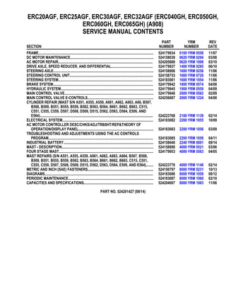
  • 1. ERC20AGF, ERC25AGF, ERC30AGF, ERC32AGF (ERC040GH, ERC050GH, ERC060GH, ERC065GH) (A908) SERVICE MANUAL CONTENTS SECTION PART NUMBER YRM NUMBER REV DATE FRAME............................................................................................................................ 524179934 0100 YRM 0558 11/07 DC MOTOR MAINTENANCE.......................................................................................... 524158039 0620 YRM 0294 03/08 AC MOTOR REPAIR...................................................................................................... 524205680 0620 YRM 1098 03/10 DRIVE AXLE, SPEED REDUCER, AND DIFFERENTIAL............................................. 524179937 1400 YRM 0285 06/10 STEERING AXLE............................................................................................................ 524158906 1600 YRM 0258 11/06 STEERING CONTROL UNIT.......................................................................................... 524158753 1600 YRM 0720 11/06 STEERING SYSTEM...................................................................................................... 524183081 1600 YRM 1054 11/06 BRAKE SYSTEM............................................................................................................ 524179942 1800 YRM 0574 04/08 HYDRAULIC SYSTEM.................................................................................................... 524179945 1900 YRM 0559 04/09 MAIN CONTROL VALVE................................................................................................ 524179946 2000 YRM 0562 02/09 MAIN CONTROL VALVE E-CONTROLS....................................................................... 524256687 2000 YRM 1224 04/08 CYLINDER REPAIR (MAST S/N A551, A555, A559, A661, A662, A663, A66, B507, B508, B509, B551, B555, B559, B562, B563, B564, B661, B662, B663, C515, C551, C555, C559, D507, D508, D509, D515, D562, D563, D564, E509, AND E564).......................................................................................................................... 524223768 2100 YRM 1139 02/14 ELECTRICAL SYSTEM.................................................................................................. 524183082 2200 YRM 1055 10/09 AC MOTOR CONTROLLER DESC/CHKS/ADJ/TRBSHT/REP&THEORY OF OPERATION/DISPLAY PANEL................................................................................. 524183083 2200 YRM 1056 03/09 TROUBLESHOOTING AND ADJUSTMENTS USING THE AC CONTROLS PROGRAM................................................................................................................. 524183085 2200 YRM 1058 04/11 INDUSTRIAL BATTERY................................................................................................. 524158040 2240 YRM 0001 09/14 MAST - DESCRIPTION................................................................................................... 524158890 4000 YRM 0521 03/06 FOUR STAGE MAST...................................................................................................... 524179953 4000 YRM 0563 04/05 MAST REPAIRS (S/N A551, A555, A559, A661, A662, A663, A664, B507, B508, B509, B551, B555, B559, B562, B563, B564, B661, B662, B663, C515, C551, C555, C559, D507, D508, D509, D515, D562, D563, D564, E509, AND E564)........ 524223776 4000 YRM 1148 02/14 METRIC AND INCH (SAE) FASTENERS....................................................................... 524150797 8000 YRM 0231 10/13 DIAGRAMS..................................................................................................................... 524183086 8000 YRM 1059 08/12 PERIODIC MAINTENANCE............................................................................................ 524183087 8000 YRM 1060 02/10 CAPACITIES AND SPECIFICATIONS........................................................................... 524204007 8000 YRM 1083 11/06 PART NO. 524201427 (09/14)
  • 2. 100 YRM 558 Description General This section has a description and the service procedures for the parts of the frame. These parts include the frame, counterweight assembly, overhead guard, hood and seat assembly, access panels, and label positions. The proce- dure for removing the traction motor is also described in this section. Description MAIN FRAME The main frame is a single weldment. See Figure 1. The main frame has mounts for the following: • Counterweight • Overhead guard • Battery restraint and hood • Seat plate (with optional seat brake) • Tilt cylinders • Steering axle • Drive axle assembly • Cowl assembly • Floor pedals and floor plates • Side step and fender weldments • Hydraulic tank • Pump and motor assemblies (steer, lift, and traction motors) • Control valves and levers The hood is part of the operator and battery restraint system. The seat is also part of the operator restraint system. The floor plates are removed for access to the steering motor. A panel in the bottom of the battery compartment is removed for access to the traction mo- tor and the hydraulic pump motor. The electronic con- troller and contactors are attached to the frame. A panel in the counterweight is removed for access to the con- troller and contactors. See Figure 16. For the location of the Master Controller and Electro-Hydraulics Valve Driver Module, see the section Electro-hydraulic Con- trol Valve 2000 YRM 1224. WARNING The battery must fit the battery compartment so that the battery restraint will operate correctly. A loose battery can cause serious injury and property damage if the lift truck overturns. Adjust the spacer plate to prevent the battery from moving more than 13 mm (0.5 in.) forward or backward. The lift trucks are equipped with an adjustable spacer plate in the battery compartment. See Figure 2. Adjust the spacer plate to control the movement of the battery in the forward and backward directions. Tighten the jam nuts on the adjustment capscrew to prevent the adjust- ment from changing. WARNING Maximum clearance between the battery and bat- tery compartment width is 13 mm (0.5 in.). Maxi- mum clearance between the battery and the spacer plate is also 13 mm (0.5 in.). The Battery Specifica- tions chart shows the minimum size compartment allowed. The weight of the battery is a large part of the coun- terweight system on an electric lift truck. Make sure that the battery is within the weight limits indicated on the Nameplate. Each model of lift truck has a cast-iron counterweight that provides the additional weight nec- essary for the indicated capacity. A slot in the overhead guard permits removal of the battery without removing the overhead guard. 1
  • 3. Description 100 YRM 558 Figure 1. Lift Truck Frame 2
  • 4. 100 YRM 558 Description Legend for Figure 1 NOTE: OPTIONAL SIDE PANELS FOR BATTERY COMPARTMENT NOT SHOWN. 1. COWL 2. BATTERY COMPARTMENT ACCESS COVERS 3. BATTERY SPACER PLATE* 4. BATTERY SPACER PLATE** 5. SIDE STEP AND FENDER WELDMENT 6. FRAME 7. FLOOR MATS 8. FLOOR PLATES (COVERS) * BATTERY SPACER PLATE USED ON NEWER LIFT TRUCK MODELS ** BATTERY SPACER PLATE USED ON OLDER LIFT TRUCK MODELS 1. BATTERY COMPARTMENT 2. BATTERY 3. BULKHEAD 4. SPACER PLATE 5. ADJUSTMENT CAPSCREW 6. JAM NUTS Figure 2. Battery Spacer Plate OTHER FRAME WELDMENTS These frame parts are the right-hand and left-hand side step and fender weldments and the cowl weld- ment. See Figure 1. Each part is a weldment fastened to the main frame to make the frame assembly. The cowl weldment is a mount for the front of the overhead guard, the steering column assembly, the release linkage of the parking brake, and the instrument panel with light switches. The display panel is on the right side of the steering column and attached to the instru- ment panel for lift truck models with SEM (Separately Excited Motor), SCR (Silicon Controlled Rectifier), and AC (Alternating Current) electronic controllers and contactors. See Figure 3, Figure 4, Figure 5, Figure 6, and Figure 7. OVERHEAD GUARD WARNING Do not operate the lift truck without the overhead guard correctly fastened to the lift truck. The overhead guard is a weldment that fastens to the main frame and cowl to help protect the operator from falling objects. See Figure 5, Figure 6, Figure 7, or Figure 9. 3
  • 5. Description 100 YRM 558 A. STANDARD SEM DISPLAY PANEL B. PREMIUM SEM DISPLAY PANEL Figure 3. SEM Display Panel NOTE: FOR LIFT TRUCK MODELS WITH AC ELECTRONIC CONTROLLERS AND CONTACTORS, BOTH THE STANDARD AND PREMIUM DISPLAY PANELS LOOK IDENTICAL. THE ONLY DIFFERENCE IS IN THE DISPLAY SOFTWARE AND THE RESULTING FUNCTIONALITY. Figure 4. AC Display Panel 4
  • 6. 100 YRM 558 Overhead Guard Replacement Overhead Guard Replacement REMOVE WARNING Do not weld, drill, grind, or cut the overhead guard for mounts, lights, or accessories. The strength of the overhead guard can be reduced. 1. Remove the battery from the truck. See How to Change Battery in your vehicle’s Periodic Main- tenance or Operating Manual. 2. Access to the capscrews that hold the rear legs of the overhead guard to the frame is from the bat- tery compartment. Remove the capscrews, wash- ers, and nuts that fasten each leg. See Figure 5, Figure 6, Figure 7, Figure 8, and Figure 9. 3. Remove the capscrews, washers, and nuts that hold each front leg of the overhead guard to the cowl. Disconnect any electric wires from under the cowl that go through the front legs of the overhead guard. When the overhead guard is lifted from the frame, make sure these electric wires move through the holes in the frame at the front and rear so that they are not damaged. 4. Use a lifting device or another person to help lift the overhead guard from the lift truck. INSTALL Put the overhead guard on the lift truck. Install any electric wires from the overhead guard legs through the holes in the frame. Install the capscrews, wash- ers, and nuts that hold each front leg to the frame. Tighten capscrews to 55 N•m (41 lbf ft). Install the capscrews, washers, and nuts that hold the rear legs to the frame. For lift truck models ERC20-30AGF (ERC040-065RF/ZF, ERC040-065RG/ZG) (E108), tighten the capscrews to 68 N•m (50 lbf ft). For lift truck models ERC20-30AGF (ERC040-065GH) (A908), tighten the capscrews to 90 N•m (66 lbf ft). Install the battery. See How to Change Battery in your vehicle’s Periodic Maintenance or Operating Manual. 5
  • 7. Overhead Guard Replacement 100 YRM 558 Figure 5. Overhead Guard, Steering Column, and Display Panel, Truck Models ERC20-30AGF (ERC040-065RF/ZF) (E108) 6
  • 8. 100 YRM 558 Overhead Guard Replacement Legend for Figure 5 NOTE: DISPLAY PANELS SHOWN ARE FOR LIFT TRUCKS WITH SCR ELECTRONIC CONTROLLERS AND CONTACTORS. A. STEERING CONTROL UNIT USED ON EARLY MODEL LIFT TRUCKS B. STEERING CONTROL UNIT USED ON LATER MODEL LIFT TRUCKS 1. OVERHEAD GUARD 2. STEERING WHEEL 3. ON-DEMAND STEERING COMPONENTS (NOT ALL UNITS) 4. HORN SWITCH CONNECTOR 5. COLUMN COVER 6. COLUMN FRAME 7. STEERING CONTROL UNIT 8. LATCH MECHANISM 9. OPTIONAL PREMIUM DISPLAY PANEL 10. REGULAR DISPLAY PANEL* 11. CAPSCREW 12. WASHER 13. NUT 14. SCREW 15. OVERHEAD GUARD HANDLE 16. HORN SWITCH CONNECTOR 17. STEERING COLUMN 18. STEERING COLUMN NUT *CURTIS METER SHOWN. PANEL AVAILABLE WITH OPTIONAL GENERAL ELECTRIC™ METER. 7
  • 9. Overhead Guard Replacement 100 YRM 558 Figure 6. Overhead Guard, Steering Column, and Display Panel, Truck Models ERC20-30AGF (ERC040-065RG/ZG) (E108) 8
  • 10. 100 YRM 558 Overhead Guard Replacement Legend for Figure 6 NOTE: DISPLAY PANELS SHOWN ARE FOR LIFT TRUCKS WITH SEM ELECTRONIC CONTROLLERS AND CONTACTORS. 1. STEERING WHEEL 2. SHIFT LEVER MECHANISM 3. COLUMN COVER 4. LATCH MECHANISM 5. STEERING CONTROL UNIT 6. COLUMN FRAME 7. ON-DEMAND STEERING COMPONENTS 8. DISPLAY PANEL (PREMIUM DISPLAY PANEL SHOWN) 9. OVERHEAD GUARD 10. CAPSCREW 11. WASHER 12. NUT 13. SCREW 14. OVERHEAD GUARD HANDLE 15. HORN SWITCH CONNECTOR 16. HORN BUTTON 17. STEERING COLUMN 18. STEERING COLUMN NUT 9
  • 11. Thank you very much for your reading. Please Click Here. Then Get COMPLETE MANUAL. NO WAITING NOTE: If there is no response to click on the link above, please download the PDF document first and then click on it.
  • 12. Overhead Guard Replacement 100 YRM 558 Figure 7. Overhead Guard, Steering Column, and Display Panel, Truck Models ERC20-30AGF (ERC040-065GH) (A908) 10
  • 13. 100 YRM 558 Overhead Guard Replacement Legend for Figure 7 NOTE: DISPLAY PANELS SHOWN ARE FOR LIFT TRUCKS WITH AC ELECTRONIC CONTROLLERS AND CON- TACTORS. NOTE: OVERHEAD GUARD FOR LIFT TRUCK MODELS ERC040-065GH (A908) SHOWN. SEE FIGURE 8 FOR OVERHEAD GUARD USED ON ERC20-30AGF (A908) MODELS. 1. ON-DEMAND STEERING COMPONENTS 2. SHIFT LEVER MECHANISM 3. STEERING WHEEL 4. DISPLAY PANEL 5. COLUMN COVER 6. COLUMN FRAME 7. STEERING CONTROL UNIT 8. COWL WELDMENT 9. DASH 10. COLUMN MOUNT 11. OVERHEAD GUARD 12. LATCH MECHANISM 13. CAPSCREW 14. WASHER 15. NUT 16. SCREW 17. OVERHEAD GUARD HANDLE 18. HORN SWITCH CONNECTOR 19. HORN BUTTON 20. STEERING COLUMN 21. STEERING COLUMN NUT Figure 8. Overhead Guard, Lift Truck Models ERC20-30AGF (A908) Legend for Figure 8 1. OVERHEAD GUARD 2. PLUG 3. NUT 4. LOCKWASHER 5. CAPSCREW 6. WASHER 7. HANDLE 8. SCREW 11
  • 14. Battery and Operator Restraint System, Hood and Seat Brake, and Seat Assembly Replacement 100 YRM 558 1. FRONT LEG, OVERHEAD GUARD 2. SETSCREW 3. ATTACHMENT PLATE 4. REAR LEG, OVERHEAD GUARD 5. COUNTERWEIGHT 6. TOW PIN 7. BOLT Figure 9. Overhead Guard and Counterweight Battery and Operator Restraint System, Hood and Seat Brake, and Seat Assembly Replacement BATTERY RESTRAINT SYSTEM WARNING On units with a shorter frame, the gas spring for the hood can raise the hood at a rapid rate and cause an injury. Do NOT bend over hood when raising hood. A battery restraint system is installed as a safety de- vice. See Figure 10. The function of the battery re- straint system, when correctly locked in the down posi- tion, is to hold the battery in the battery compartment if an accident causes the lift truck to tip over. The bat- tery restraint is a steel weldment that is connected to the frame with a hinge. A sliding latch mechanism (see Fig- ure 10.) locks the battery restraint in the down position for operation. The latch, at the top center of the coun- terweight, unlocks the battery restraint from the frame, so that the battery restraint can be raised to the up po- sition for access to the battery. The battery restraint is also the support for the hood. A gas spring helps lift the hood assembly. A rod is used to hold the hood in the up position on units with a longer frame. The oper- ator must hold the hood assembly with one hand. Use the other hand to move the rod to the storage position. Lower the hood and battery restraint assembly to the operating position. Make sure that the battery restraint is correctly locked to the frame for operation of the lift truck. 12
  • 15. 100 YRM 558 Battery and Operator Restraint System, Hood and Seat Brake, and Seat Assembly Replacement 1. HOOD 2. SEAT 3. LATCH ASSEMBLY 4. BATTERY RESTRAINT AND HOOD FRAME 5. GAS SPRING 6. HINGE 7. STOP ROD 8. RELEASE LABEL FOR STOP ROD 9. COUNTERWEIGHT 10. LATCH HANDLE 11. LIFT HANDLE 12. LATCH WARNING LABEL Figure 10. Hood, Latch, and Battery Restraint System WARNING Correct operation of the battery restraint system re- quires that the battery does not move more than 13 mm (0.5 in.) horizontally. Make sure that the bat- tery spacer plate is correctly adjusted. WARNING The battery restraint and its latch mechanisms must operate correctly before a lift truck is operated. To operate correctly, the battery restraint must be locked in the down position. The battery compartment has an adjustable spacer plate, which is used to prevent for- ward and backward movement of the battery. Adjust the spacer plate to prevent movement in any one horizontal direction of 13 mm (0.5 in.) maximum. See Figure 2. Raise the seat. Use the knob for the latch to release the battery restraint. See Figure 10. Use the handle on the hood to raise the battery restraint and hood. Make sure that the battery cannot move more than a total of 13 mm (0.5 in.) in any one horizontal direction. Make sure the spacer plate is correctly adjusted to prevent movement. Push the hood and the battery restraint down until the latch locks. Make sure the battery restraint is locked se- curely. Lift on the handle to make sure it is latched and will not move. HOOD The hood must be locked in the down position dur- ing operation. The battery must have the spacer plate correctly adjusted to prevent forward or back- ward movement of 13 mm (0.5 in.) maximum. On lift trucks ERC20-30AGF (ERC40-065RF/ZF, ERC40-065RG/ZG) (E108), if the unit has a seat brake, raise the seat and seat plate assembly. Use the latch handle at the rear of the hood (see Figure 11) to release the hood frame and battery restraint. Raise the latch handle and slide the handle toward the right side of the truck. A spring moves the handle back to the left. Use the lift handle by the seat to raise the hood. See Figure 11. A gas spring and stop rod will hold the as- sembly in the up position. Make sure that the battery cannot move more than a total of 13 mm (0.5 in.) in any one horizontal direction. If necessary, adjust the battery spacer plate as shown in Figure 2. 13
  • 16. Battery and Operator Restraint System, Hood and Seat Brake, and Seat Assembly Replacement 100 YRM 558 1. HINGE 2. LIFT HANDLE 3. HOOD 4. LATCH HANDLE 5. SEAT BRAKE PLATE Figure 11. Hood and Seat Brake Plate Assembly, Lift Truck Models ERC20-30AGF (ERC40-065RF/ZF, ERC40-065RG/ZG) (E108) Release the stop rod by moving it to the right before low- ering hood. See the label in Figure 10. Make sure the latch handle is fully to the right when closing the hood so that the latch can engage the latch piece. Make sure the hood is locked securely. Try to raise the hood using only the lift handle to make sure the hood is latched and will not move. HOOD WITH E-HYDRAULICS WARNING The gas spring for the hood can raise the hood at a rapid rate and cause an injury. DO NOT lean over hood when raising hood. WARNING The batteries for these lift trucks must fit the battery compartment width with a maximum of 13 mm (0.5 in.) clearance. The Battery Specifications, at the back of this manual, shows the minimum sizes of the battery compartment. Another important part of the battery restraint system is the steel weldment that is also the hood frame. This hood frame is connected to the lift truck frame with hinges at the rear of the hood. Gas springs help lift the hood assembly. The seat and other parts of the opera- tor restraint system fasten to the hood assembly. NOTE: Before raising the hood, move the steering col- umn to the forward position and slide the seat all the way back, and If necessary, move the armrest all the way back. See Figure 12. 1. ARMREST ADJUSTMENT HANDLE Figure 12. Armrest Latch Location The latch that secures the cover for the hood release handle can be either a locking or non locking latch. If the latch is a locking latch, unlock latch with key first. The cover, latch and hood release handle are located on the right side of the hood. See Figure 13. Pull the latch handle, located on the top of the latch, to the up position and then pull on latch handle to move cover away from hood release handle. Pull hood re- lease handle up to release hood latch mechanism. See Figure 13. Use handle on the hood to place hood in the raised position. 14
  • 17. 100 YRM 558 Battery and Operator Restraint System, Hood and Seat Brake, and Seat Assembly Replacement Before lowering the hood, make sure the battery re- straint rod is over the battery. Lower the hood and push hood release handle down to secure hood to frame. Move cover over hood release handle and push latch handle down to secure cover to hood. If latch is a lock- ing latch, lock latch with key. 1. LATCH 2. COVER 3. HOOD RELEASE HANDLE 4. HOOD LATCH MECHANISM 5. COMPRESSION SPRING 6. PIN 7. SCREW 8. CAPSCREW 9. NUT 10. LOCKWASHER 11. WASHER 12. LATCH HANDLE Figure 13. Latch and Cover With E-Hydraulics SEAT BRAKE On ERC20-30AGF (ERC40-065RF/ZF, ERC40-065RG/ ZG) (E108) units with a seat brake, there is a separate plate with a hinge fastened to the front of the battery compartment (see Figure 11.) The seat is fastened to this plate instead of the hood on these units. The link- age for the seat plate has a spring that holds the plate up and applies the brake on the rear of the traction mo- tor. During operation of the lift truck, the seat brake will be applied to the traction motor if the seat brake switch, located under the seat, senses that the operator has left the seat and the parking brake has not been ap- plied. On these units, push the seat and seat plate into position over the hood. See Figure 11 and Figure 14. OPERATOR RESTRAINT SYSTEM AND SEAT ASSEMBLY The seat belt, hip restraint brackets, seat and mounting, hood, and latches are all part of the operator restraint system. Each item must be checked to make sure it is attached securely, functions correctly, and is in good condition. See Figure 14. Automatic Locking Retractor (ALR) NOTE: ERC20-30AGF (ERC40-065RF/ZF, ERC40- 065RG/ZG) (E108) lift trucks produced before Novem- ber 2005 are equipped with the ALR type seat belts. The seat belt must fasten securely. Make sure the seat belt extends and retracts smoothly and is not frayed or torn. If the seat belt is damaged or does not operate properly, it must be replaced. See Figure 14. 1. SEAT 2. HIP RESTRAINT 3. SEAT BELT AND MOUNT 4. HOOD 5. SEAT RAILS 6. SEAT PLATE (WITH SEAT BRAKE)* *THE SEAT PLATE IS NOT USED ON ERC20-30AGF (ERC040-065GH) (A908) TRUCKS. Figure 14. Operator Restraint and Seat Assembly 15
  • 18. Battery and Operator Restraint System, Hood and Seat Brake, and Seat Assembly Replacement 100 YRM 558 Emergency Locking Retractor (ELR) NOTE: Lift trucks produced after November 2005 are equipped with the Emergency Locking Retractor (ELR) style seat belt. When the ELR style seat belt is properly buckled across the operator, the belt will permit slight operator reposi- tioning without activating the locking mechanism. If the truck tips, travels off a dock, or comes to a sudden stop, the locking mechanism will be activated and hold the operator’s lower torso in the seat. A seat belt that is damaged worn or does not operate properly will not give protection when it is needed. The end of the belt must fasten correctly in the latch. The seat belt must be in good condition. Replace the seat belt if damage or wear is seen. See Figure 15. The following seat belt operation checks must be per- formed: • With the hood closed and in the locked position, pull the seat belt slowly from the retractor assembly. Make sure the seat belt pulls out and retracts smoothly. If the seat belt does not pull out of the retractor assem- bly, the internal latch may be locked. Pull firmly on the seat belt and hold for a moment to remove slack from the belt in the retractor. Release the seat belt. Seat belt will retract and the internal latch will unlock. If the seat belt cannot be pulled from the retractor as- sembly or the belt will not retract, replace the seat belt assembly. • With the hood closed and in the locked position, pull the seat belt with a sudden jerk. Make sure the seat belt will not pull from the retractor assembly. If the seat belt can be pulled from the retractor, when it is pulled with a sudden jerk, replace the seat belt as- sembly. • With the hood in the open position, make sure the seat belt will not pull from the retractor assembly. If the seat belt can be pulled from the retractor, with the hood in the open position, replace the seat belt assembly. Make sure the seat rails and latch striker are not loose. The seat rails must lock securely in position but move freely when unlocked. The seat rails must be securely attached to the mounting surface. The hood must be fully closed. Lift the hood to make sure it is closed and will not move. Adjust hood, hood latch, and latch striker when any of the parts of the operator restraint system are installed or replaced. See the section Hood Repair in this manual for the adjustment procedures for the hood. 1. OPERATOR WEIGHT ADJUSTMENT 2. FORWARD/BACKWARD ADJUSTMENT 3. SEAT BELT 4. HIP RESTRAINT 5. SEAT 6. SEAT RAIL Figure 15. Hood and Seat Check 16
  • 19. 100 YRM 558 Counterweight Replacement Counterweight Replacement If the lift truck must be put on blocks for maintenance or repair, see How to Put Lift Truck on Blocks in the Operating Manual or Periodic Maintenance section for your vehicle. WARNING The counterweight is very heavy. Make sure that the crane and lifting devices have enough lifting capac- ity to safely lift the counterweight. The weights of the counterweights are shown in Table 1. The counterweight normally is not removed for most re- pairs. Replacement of the SCR Electronic Controllers is easier with the counterweight removed. Replace- ment of the SEM, and AC Controllers is accomplished by removing the cover from the counterweight. See Fig- ure 16. The counterweight is fastened to the frame with four capscrews. The weights for the counterweights are shown in Table 1. 1. SEAL 2. COUNTERWEIGHT 3. TOW PIN 4. ACCESS COVER 5. UPPER CAPSCREW AND WASHER 6. LOWER CAPSCREW AND WASHER 7. COVER CAPSCREWS AND WASHERS Figure 16. Counterweight Assembly Table 1. Counterweights Model (mm*) Weight + 50 kg (110 lb) 0 kg (0 lb) ERC040-050RF/ ZF, RG/ZG (E108) and ERC040-050GH (A908) 700 578 kg (1274 lb) ERC040-050RF/ ZF, RG/ZG (E108) and ERC040-050GH (A908) 786 794 kg (1750 lb) ERC20-25AGF (E108) and ERC040-060RF/ ZF, RG/ZG (E108) and ERC20-25AGF (A908) and ERC040-060GH (A908) 847 942 kg (2076 lb) ERC30AGF (E108) and ERC065RF/ZF, RG/ZG (E108) and ERC30AGF (A908) and ERC065GH (A908) 933 942 kg (2076 lb) *Approximate battery compartment lengths. REMOVE 1. Remove the battery from the truck. See How to Change Battery in your vehicle’s Periodic Main- tenance or Operating Manual for the procedures. 17