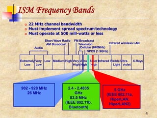
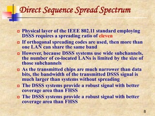
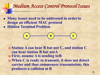
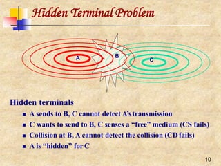
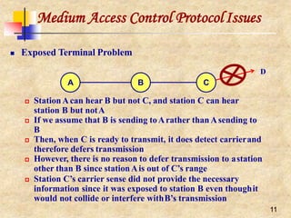
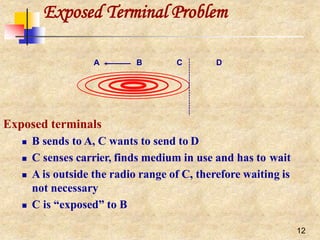
The document discusses various wireless networking technologies including wireless LANs, PANs, MANs and WANs. It focuses on wireless LANs which use the IEEE 802.11 standards. It describes some of the key benefits of wireless LANs like mobility and untethered access. It then discusses different transmission techniques used in wireless networks including pulse transmission, basic modulation, and spread spectrum. It elaborates on spread spectrum techniques like frequency hopping and direct sequence spread spectrum used in wireless LANs. Finally, it covers some medium access control protocol issues in wireless networks like hidden and exposed terminal problems, and solutions using techniques like carrier sensing, RTS/CTS and congestion avoidance.


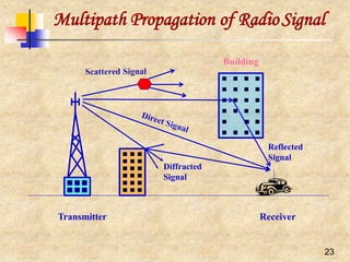
![Medium Access Control ProtocolIssues
Copyright © 2006, Dr. Carlos Cordeiro and Prof. Dharma P.Agrawal, All rights reserved. 16
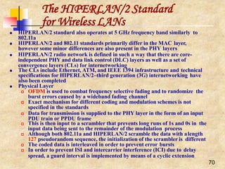
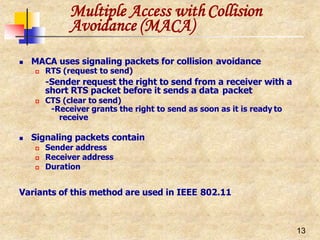
CollisionAvoidance
To minimize collisions, wireless CSMA/CA MAC
protocols often use collision avoidance techniques in
conjunction with a carrier sense
Collision avoidance is implemented by making node
wait for a randomly chosen duration before attempting
to transmit after the channel is sensed idle
CongestionAvoidance
When a node detects the medium to be idle, it chooses a
backoff interval between [0, CW], where CW is called
contention window
CW usually has a minimum (CW_min) and
maximumvalue (CW_max)](https://image.slidesharecdn.com/wlan-221019012503-f69dfd2e/85/WLAN-pptx-16-320.jpg)
![Medium Access Control ProtocolIssues
18
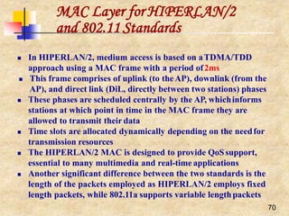
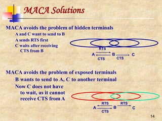
Other MAC Issues
Many other issues need to be considered such asfairness
Fairness has many meanings and one of them might saythat
stations should receive equal bandwidth
Unfairness will eventually occur whenone node backs off
much more than some other node in the sameneighborhood
MACAW’s solution to this problem [Bharghavan1994] is to
append the contention window value (CW) to packets anode
transmits, so that all nodes hearing that CW, use it for their
future transmissions
Since CW is an indication of the level of congestion inthe
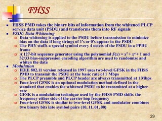
vicinity of a specific receiver node, MACAWproposes
maintaining a CW independently for eachreceiver
All protocols discussed so far are sender-initiatedprotocols
In other words, a sender always initiates a packet transfer to
a receiver
The receiver might take a more active role in the processby
assisting the transmitter in certain issues such as collision
avoidance, and some sort of adaptive rate control](https://image.slidesharecdn.com/wlan-221019012503-f69dfd2e/85/WLAN-pptx-18-320.jpg)
![28
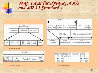
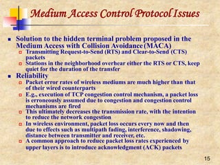
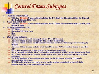
IEEE 802.11 and the11-Chip
Barker Sequence
Peaks when correlating the sequence Peaks when correlating a received sequence
‘10’ with the 11-chip Barker sequence with the 11-chip Barker sequence
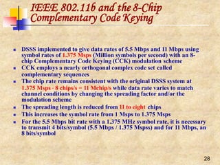
11-chip Barker sequence [1, 1, 1, -1, -1, -1, 1, -1, -1, 1, -1] is the PN chosen for
DSSS PHY layer
Its autocorrelation shows some very sharp peaks when the transmitter and
the receiver are synchronized
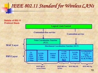
The first IEEE 802.11 standard used a symbol rate of 1 Mega-symbol per
second (Msps) yielding a 11 MHz chipping rate with the Barker sequence, and
data rates of 1 Mbps (using DBPSK) and 2 Mbps (usingDQPSK)](https://image.slidesharecdn.com/wlan-221019012503-f69dfd2e/85/WLAN-pptx-27-320.jpg)
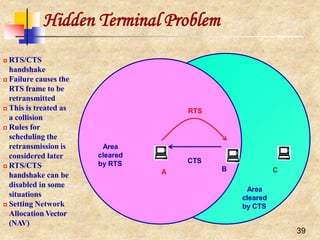
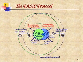
![44
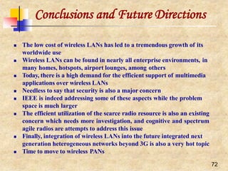
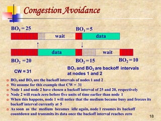
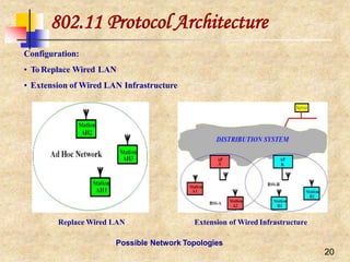
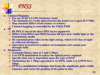
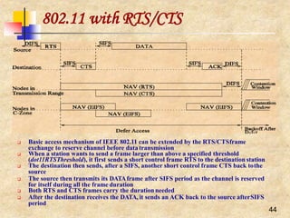
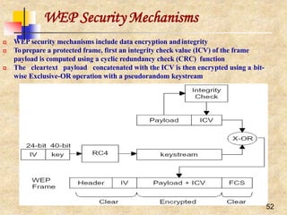
Distributed Coordination Function (DCF)
Two forms of carrier sensing:
physical (by listening to the wireless
shared medium) and virtual
Virtual carrier sensing uses the
duration field to set a station’s NAV
which is included in the header of
RTS and CTS frames
If medium found idle for more than a
DIFS period, then the frame can be
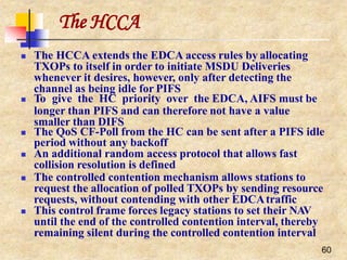
transmitted
Otherwise, the transmission is
deferred and the station uses an
Exponential Random Backoff
Mechanism by choosing a random
backoff interval from [0, CW]
If collision occurs, the station doubles
its CW
At the first transmission attempt, CW
= CWmin and is doubled at each](https://image.slidesharecdn.com/wlan-221019012503-f69dfd2e/85/WLAN-pptx-43-320.jpg)
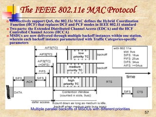
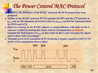
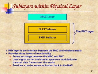
![The IEEE 802.11e MAC Protocol
58
Each backoff sets a counter to a random number drawn from the interval
[1;CW+1]
When the medium is determined busy before the counter reaches zero, the backoff
has to wait for the medium being idle for AIFS again, before resuming the count
down process
When the medium is determined as being idle for the period of AIFS, the backoff
counter is reduced by one beginning the last slot interval of the AIFS period
After any unsuccessful transmission attempt, a new CW is calculated with the help
of the persistence factor (PF), PF[TC], and another uniformly distributed backoff
counter out of this new, enlarged CW is drawn, so that the probability of a new
collision is reduced
PF to increase the CW differently for each TC and is given by:
n e w C W [ T C ] ( ( o l d C W [ T C ] 1) P F ) 1
CW never exceeds the parameter CWmax[TC]
A single station may implement up to eight transmission queues realized as virtual
stations inside a station, with QoS parameters that determine their priorities
If the counters of two or more parallel TCs in a single station reach zero at the same
time, a scheduler within the station avoids the virtual collision
There is still a possibility that a transmitted frame could collide at the wireless
medium with a frame transmitted by other stations
Another important part is the TXOP which is an interval of time when a station has
the right to initiate transmissions, defined by a starting time and a maximum
duration](https://image.slidesharecdn.com/wlan-221019012503-f69dfd2e/85/WLAN-pptx-58-320.jpg)
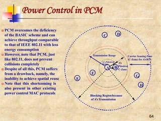
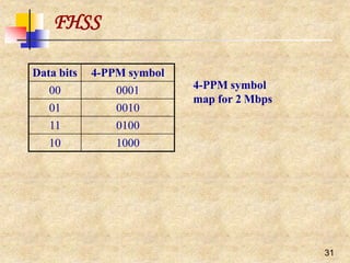
![Virtual back of eight trafficcategories
s
s
60
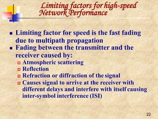
Virtual back of eight traffic categories
(1) Left: legacy DCF close to EDC,A with AIFS=34, C Wmin=15, PF=2;
(2) Right: EDCA with AIFS[TC] 34, C W min [TC]=0-255,PF[TC]=1-16](https://image.slidesharecdn.com/wlan-221019012503-f69dfd2e/85/WLAN-pptx-59-320.jpg)