
Recommended

Recommended
More Related Content
What's hot
What's hot (13)
Viewers also liked
Viewers also liked (18)
Similar to Guide for Stripping and Crimping Cable Conductors
Similar to Guide for Stripping and Crimping Cable Conductors (20)
More from Phil Heft
More from Phil Heft (20)
Recently uploaded
Recently uploaded (20)
Guide for Stripping and Crimping Cable Conductors
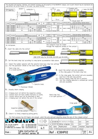
- 1. conductorStripping Jacket Example with: female 30-4305 Visual mark "M" min.DCable A CF 1.5 B The conductor must be visible through the inspection window of the contact END STOP male 30-3305 HP contact series 30HP contact series 30HP contact series 30HP contact series 30 Tel. : +33 (0)4.50.36.13.85Tel. : +33 (0)4.50.36.13.85Tel. : +33 (0)4.50.36.13.85Tel. : +33 (0)4.50.36.13.85 Echelle/Scale Cable instruction ofCable instruction ofCable instruction ofCable instruction of 2/3 A4Item :Item :Item :Item : Page used without the written consent of the owner. Law dated 11.03.1902 Ind. Date ModificationFax : +33 (0)4.50.36.11.33Fax : +33 (0)4.50.36.11.33Fax : +33 (0)4.50.36.11.33Fax : +33 (0)4.50.36.11.33 Drawn Checked Edition originale 4:1 21/07/10 A.V.a C.G. b 07/09/10 A.V.C.G.Modif. Toolsetting for 30-X320 Folder : X:MéthodesDocumentationsInstruction de cablage Approved E.M. Ref : IC30HP02Ref : IC30HP02Ref : IC30HP02Ref : IC30HP02 This document and drawings, sketches, and schematic drawings are the property of the NICOMATIC company. and no parts thereof may be reproduced and E.M. Web : www.nicomatic.comWeb : www.nicomatic.comWeb : www.nicomatic.comWeb : www.nicomatic.com 173, rue des fougères173, rue des fougères173, rue des fougères173, rue des fougères Z.I. Les BracotsZ.I. Les BracotsZ.I. Les BracotsZ.I. Les Bracots F-74890 Bons-en-ChablaisF-74890 Bons-en-ChablaisF-74890 Bons-en-ChablaisF-74890 Bons-en-Chablais Selector knob. Hand crimp tool End of the contact 4.2 - Contact must not have visible fractures or cracks. 4.1 - Crimping must not deform the inspection window. Crimp guide. 5555 - Check it is firmly crimped by pulling gently For that purpose two (2) fingers are enough : pinch the wire and pull smoothly along the axis of the crimped contact in an open position. Positioner C16460. 3.2 - During crimping, keep the wire in position. 4444 - Visually check crimping 4.4 - Crimping must not deform the end of the contact 4.3 - Contact barrel must not be deformed or bent. must be in the end stop position. and wire assembly. 3.3 - Just one crimping operation is allowed per contact in a closed position. 3333 - Insert the contact and wire assembly in the crimp guide of the hand crimp tool. 3.1 - In the crimp guide, the contact and wire assembly Hand crimp tool Inspection window 2222 - Set the hand crimp tool according to crimp barrel accomodation table above. 2.1 - Select the number selector with the selector knob (see crimp tool setting). 2.2 - Put the positioner C16460 on the hand crimp tool 16459. END STOP only for 30-X310, 30-X315 and 30-X320 1111 - Insert the cable into the contact AWG20 AWG18 AWG16 AWG14 AWG12 AWG20 AWG18 AWG16 AWG14 AWG12 3305 30-3305 X 1.1 mm 1.65 mm x3 3 3308 30-3308 NA X 1.35 mm 1.85 mm x2 NA 4 3310 30-3310 1.7 mm x1 4 4 5 3315 30-3315 X NA 2 mm 6 NA 3320 30-3320 NA X 2.6 mm 5.3 mm 5.5 mm NA 8 AWG20 AWG18 AWG16 AWG14 AWG12 AWG20 AWG18 AWG16 AWG14 AWG12 4305 30-4305 X 1.1 mm 1.65 mm x3 3 4308 30-4308 NA X 1.35 mm 1.85 mm x2 NA 4 4310 30-4310 1.7 mm x1 4 4 5 4315 30-4315 X NA 2 mm 6 NA 4320 30-4320 NA X 2.6 mm 5.3 mm 5.5 mm NA 8 NA 4.5 mm NA16459 / C16460 NA NA NA NA NA : Not Applicable Crimp tool setting - Number selector Crimp tool setting - Number selector NA NA OK OK 16459 / C16460 NA NA X 6.2 mm NA NA NA NA X NA NA ØB ØCLoaded Unloaded Length D hole NA M 6 mm Loaded 6.2 mm NA NA Unloaded ØB Cable A Cable A Length D hole M Crimp by AF8 Tool / Positioner Solder Crimp by AF8 Tool / Positioner Solder ØC Length F conductor 4.5 mm Length F conductor NA 6 mm