1. How Encoder-triggered Image
Acquisition Improves Part Inspection
By Pete Kepf, Senior Vision Application Consultant
Introduction / Summary
Over the years, manufacturers of all types of products have deployed literally thousands of machine
vision systems to inspect parts for quality. These applications range from packaging inspection to
document processing to gauging metal stampings. In industries such as publishing, consumer products,
pharmaceuticals, electronics and plastics one material handling characteristic has always presented a
unique challenge: how to address changes in line speed. Integrating an encoder with the conveyor and
feeding that information to the vision system has been the traditional method to address that issue.
Many encoder vendors provide calibration software for their products, making setup quick and easy.
Alternatively, writing a simple app to incorporate the encoder variables (pulses/ revolution, revolutions/
distance) and conveyor variables (distance/ time) will provide distance rather than time based image
acquisition. Part inspection can be greatly improved using an encoder when line speed may change.
Problems Associated with Changes in Line Speed
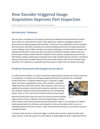
To understand the problem, it is useful to review the image acquisition process and compare stationary
to moving parts. In a typical non-moving part application the part is positioned into a repeatable
location each time it is inspected. When the part is in position a trigger
signal, from either a photoelectric sensor or the controller, initiates the
image acquisition on the vision camera. After acquisition, vision tools are
applied and calculations are performed to determine whether or not the
part attributes conform to those previously defined. The corresponding
output, “pass” or “fail” is sent to the controller and the process repeats.
Because the part position does not move from frame to frame the lighting
angle remains constant, no dynamic vision tool repositioning is required
and all relevant areas of the part within the field of view (FOV). Figure 1 is an example of an indexed
(stationary) part where the attributes to be inspected, in this case the label and the rod, are in a
repeatable position from frame to frame. In fact, should either be missing or out of location, the part is
considered a reject.
In contrast, when the part is moving, the trigger is initiated when the part is upstream of the vision
system camera. As the part moves, the sensor detects its leading edge and sends a signal that tells the
Figure 1
2. vision system when to take a picture. Because the part is moving, there is a time delay between the
sensor and the vision system. This delay depends on the speed of the part and the physical distance
between the sensor and the vision camera. In order for the part to be in a repeatable location within the
FOV, the line speed must be constant and the trigger must be precise.
Figure 2
When part speed may vary, a distance rather than time based delay is advantageous. This involves
replacing the part presence sensor trigger with that of an encoder. Figure 2 illustrates what happens
when the speed of the part changes while the distance between the part presence and imaging sensors
remains the same.
In the leftmost picture, the part is located near the center of the FOV, the preferred location for the part
within the image window. This location provides maximum flexibility for the vision tool application. As
line speed increases, the image will be displaced towards the right (center image); as part speed
decreases the image will be displaced to the left (rightmost image). Depending on the application, either
of these two slight positional displacements may be acceptable, but extremes at either side should be
avoided. There are two primary reasons for this, lighting and dynamic tool location. Regarding lighting, it
is possible that the inspection relies upon the angles among the light source, the part and the vision
sensor. Differences in location would affect these angles and, hence, the inspection.
Dynamic tool location is the location of the part within the FOV with software. To compensate for the
slight variation in line speed and the resulting part position shift, the manufacturer may add to the
inspection system a “locate tool,” software that adjusts for slight variations in part position. The locate
tool allows for reliable detection of the part itself, and the subsequent application of an inspection tool
determines the presence of the feature on the part. However, real world execution of a locate tool adds
time to the inspection process. Variables such as
processor power and size of the search window can
also affect inspection tool location, especially in high-
speed applications where a locate tool may limit the
maximum rate of inspection.
A third, extreme possibility is when line speed changes
are of an order of magnitude that that the vision
sensor has no way of even knowing which part in the
queue it is inspecting. Figure 3 illustrates what
happens in an inspection where the presence of a
Figure 3
3. bottle cap is to be detected. At Time0, Position 0 the
presence of a bottle missing a cap is detected. At
Time 1, Position 1 the bottle is at the vision sensor
and the missing cap is detected. At Time 2, Position 2
the non-conforming bottle is rejected.
Contrast this with what happens as illustrated in
Figure 4, when the line speed doubles.
Just as in the previous example, At Time0, Position 0
the presence of a bottle missing a cap is detected.
However, at Time 1, the bottle with the missing cap
is at Position 2 (line speed doubled). At Position 1 is a
bottle with a cap. The missing cap is not detected
and continues through the process.
Solution: Adding a Distance Component Using an Encoder
Figure 5
An encoder is an electromechanical device that transforms rotational information into a series of pulses.
Typically, it is comprised of a disk featuring a series of optical or magnetic divisions on it. This disk
rotates about a shaft that is coupled to a motion device such as a conveyor. As the conveyor travels, the
encoder shaft and optical disk rotate. The resulting pulse output is directly related to the physical
motion of the conveyor. Encoders come in a variety of form factors as illustrated in Figure 5.
Encoders are specified in Pulses Per Revolution (PPR). Calibration of distance to pulses is easy and
straightforward using the following formula:
(PPR) / (2*pi*shaft radius) = pulses per unit of measure
Figure 4
4. For example, if the encoder is rated at 1,024 PPR and is coupled to a 50 mm diameter shaft then
1,024/ (2 * 3.1417 * 25) = 6.52 pulses per mm.
To carry this example a step further, if the conveyor pulleys and gears are at a 1,000 to 1 ratio (1,000
rotations of the motor to 1 unit of travel), then our pulse calculation is:
100 mm/ sec = 6.52 pulses/mm x 1000
= 6,520 pulses/second or
100 mm = 6,520 pulses.
This calculated value can be placed into the vision software as a pulse-to-distance calibration factor.
When installed on a conveyor, an encoder provides a series of pulses proportional to the linear motion
of the belt. If an encoder input is coupled with a part presence trigger, the distance-based image
acquisition compensates for any changes in conveyor speed. The vision sensor can be calibrated in
corresponding units of measure so that output pulses directly correspond to distance traveled. The
encoder replaces the time delay function with one based on distance. The image remains centered
within the field-of-view, and part inspection is more robust.
Conclusion
Inspection of moving parts can be problematic, particularly when line speeds change. The addition of an
encoder replaces the traditional, time-based image acquisition delay with one that is distance-based.
This reduces positioning errors within the Field Of View and the accompanying issues, lighting angle
changes and dynamic tool location, as well as eliminating the possibility of inspecting the wrong part
should a gross difference in line speed occur.