Waves And Tidal Flat Ecosystems 1st Edition Prof Eiichi Baba
Waves And Tidal Flat Ecosystems 1st Edition Prof Eiichi Baba
Waves And Tidal Flat Ecosystems 1st Edition Prof Eiichi Baba
Waves And Tidal Flat Ecosystems 1st Edition Prof Eiichi Baba
Waves And Tidal Flat Ecosystems 1st Edition Prof Eiichi Baba
1.
Waves And TidalFlat Ecosystems 1st Edition Prof
Eiichi Baba download
https://ebookbell.com/product/waves-and-tidal-flat-
ecosystems-1st-edition-prof-eiichi-baba-4285950
Explore and download more ebooks at ebookbell.com
2.
Here are somerecommended products that we believe you will be
interested in. You can click the link to download.
Wave And Tidal Energy Carlos Guedes Soares Matthew Lewis
https://ebookbell.com/product/wave-and-tidal-energy-carlos-guedes-
soares-matthew-lewis-55252176
Wave And Tidal Generation Devices Reliability And Availability Peter
John Tavner
https://ebookbell.com/product/wave-and-tidal-generation-devices-
reliability-and-availability-peter-john-tavner-6839146
Wave And Tidal Energy Deborah Greaves Gregorio Iglesias Eds
https://ebookbell.com/product/wave-and-tidal-energy-deborah-greaves-
gregorio-iglesias-eds-7014010
Electrical Design For Ocean Wave And Tidal Energy Systems Raymond
Alcorn
https://ebookbell.com/product/electrical-design-for-ocean-wave-and-
tidal-energy-systems-raymond-alcorn-4589052
3.
Water Wave AndTidal Power Richard Spilsbury Louise Spilsbury
https://ebookbell.com/product/water-wave-and-tidal-power-richard-
spilsbury-louise-spilsbury-4762936
Marine Tidal And Wave Energy Converters Technologies Conversions Grid
Interface Fault Detection And Faulttolerant Control Illustrated
Mohamed Benbouzid Editor
https://ebookbell.com/product/marine-tidal-and-wave-energy-converters-
technologies-conversions-grid-interface-fault-detection-and-
faulttolerant-control-illustrated-mohamed-benbouzid-editor-36371946
The Great Super Cycle Profit From The Coming Inflation Tidal Wave And
Dollar Devaluation 1st Edition David Skarica
https://ebookbell.com/product/the-great-super-cycle-profit-from-the-
coming-inflation-tidal-wave-and-dollar-devaluation-1st-edition-david-
skarica-2526348
Assessment And Nonlinear Modeling Of Wave Tidal And Wind Energy
Converters And Turbines Madjid Karimirad
https://ebookbell.com/product/assessment-and-nonlinear-modeling-of-
wave-tidal-and-wind-energy-converters-and-turbines-madjid-
karimirad-54701136
Renewable Energy From The Oceans From Wave Tidal And Gradient Systems
To Offshore Wind And Solar Domenico P Coiro
https://ebookbell.com/product/renewable-energy-from-the-oceans-from-
wave-tidal-and-gradient-systems-to-offshore-wind-and-solar-domenico-p-
coiro-48771330
Preface
In this book,the authors address present-day methodology to explore natural
phenomena. Highly advanced computational fluid mechanics contributes to the
rationalization of experimental work. By taking sandy beach and tidal flat eco-
systems as an example, results from interdisciplinary collaboration between envi-
ronmental experimentalists and applied mathematicians are presented in an inte-
ractive manner.
In 1994, an environmental study group from Hiroshima University started a
study on tidal flats. Based on fieldwork, they discovered the importance of fluid
flow in understanding the biological activities of tidal flats and sandy beaches.
They found that the number of bacteria on the seabed strongly correlates with the
amount of silt (fine sand < 50 micron). Larger slopes produce smaller amounts of
silt. They noted the importance of an appropriate slope for a tidal flat where sound
biological activities are carried out on the seabed.
Furthermore, independently in 1993, an applied mathematics group from Chiba
University studied a sliding problem of two different media. In 1995, they exten-
ded their work to explain a penetration problem from one side to the other in dif-
ferent phases. Then, in 1996, the study was extended to wave motion on the slo-
ping sandy beach. At this moment this mathematics group did not exploit yet their
potential to explore coastal environmental problems.
In 1997, the environmental group started a research project dealing with the ef-
fect of spilled oil on coastal ecosystems. This project aims to provide measures to
counter environmental disasters such as the spilled oil in 1997 from a tanker in the
Japan Sea. In this study, a new experimental discovery was made about the role of
waves over a sandy beach. Breaking waves act as a pump to transport fresh sea-
water to the beach. Thus, it became possible to estimate quantitatively the infiltra-
tion of seawater by waves into the seabed.
Even though the waves themselves are only a few centimeters high, the impor-
tance of waves was recognized from experimental studies using a tidal flat sumu-
lator, which contains actual soil from the tidal flat. That is, benthos grows in the
seabed when waves and tides act together over the tidal flat. However, the number
of benthos decreases and sea grass grows instead when the tide alone acts without
waves. Sea grass prevents the infiltration of fresh seawater into the seabed. Thus,
it was clear that different kinds of organisms flourish under different habitat con-
ditions, i.e., with waves or without waves. Thus waves at the margin of sandy
10.
VI
beaches or tidalflats are an important factor for the determination of coastal eco-
systems.
The environmental experiment group needed rationalization of their experi-
mental results from a theoretical standpoint. The Chiba University mathematics
group was informed of the flow phenomenon observed in experiments by one of
the environmental study groups in 1998. These experimental results attracted and
inspired the mathematics group to exploit the large potential to explore the flow
phenomenon inside the seabed. They then extended their analysis to treat fluid
flow in various environments such as air, wet sand and dry sand. It was found that
mathematically simulated flow behaviour inside a sloping beach well explained
observed phenomena. Thus, the flow phenomena observed by the einvironmented
study group were rationalized.
The einvironmental study group continued their work and found that spilled oil
over a sloping beach prevents the infiltration of fresh seawater into the seabed,
causing a shortage of oxygen. Therefore, the benthos suffers.
The mathematics group extended their work to simulate bahaviour and decom-
position of spilled oil based on Navier-Stokes equations with the Bingham fluid
model for oil. Multi-phase flow analyses were made. In this study, decomposition
of spilled oil by bacteria is simulated as a chemical reaction. Thus, natural phe-
nomena around the margin of land, in other words, the margin of different dis-
ciplinary research fields are being explored by collaboration of experimentalists
and applied mathematicians. The development of this work in the future is highly
expected to further our understanding of coastal ecosystems and to contribute to
sound engineering approaches in the construction of artificial tidal flats and co-
astlines.
March 2003
Eiichi Baba
Hideo Kawarada
Mitsumasa Okada
The following authors contributed to this book:
Chapter 1; W. Nishijima
Chapter 2; E. Baba
Chapter 3; H. Kawarada and H. Suito
Chapter 4; M. Okada
Chapter 5; H. Kawarada and H. Suito
Chapter 6; M. Okada
Chapter 7; H. Kawarada and H. Suito
Chapter 8; H. Kawarada and H. Suito
Chapter 9; H. Kawarada and H. Suito
VIII Table ofContents
3 Unified model for wave breaking action. . . . . . . . . . . . . . . . . . . . . . .. 41
3.1 Introduction 41
3.2 Mathematical model. . . . . . . . .. . . . . . . . . . . . . . . . . .. . . . . . . . . . .. 42
3.2.1 Notations and geometry 42
3.2.2 Conservation of mass for total flow system 44
3.2.3 Conservation of momentum for total flow system 44
3.2.4 Surface blocking effect to seawater due to
accumulated materials on the beach . . . . . . . . . .. . . . . .. 45
3.3 Unified model for two-phase flow with surface blocking effect. 46
3.4 Numerical results 47
3.4.1 Correlation between wave breaking action on a
sloping beach and internal flow of a sandy beach ..... 47
3.4.2 Flow pattern and infiltration area of seawater in
sandy beach . . . . . . . . .. . . . . . . . . . . . . . . . . . . .. . . . . . . . .. 48
3.4.3 Time averaged flow under the beach. . . . .. . . . . . . . . ... 50
3.4.4 Surface blocking effect to seawater 51
4 Oil pollution: human damages on hydraulic regime in sandy
beach ecosystems. . . . . . . . . . . . . . . . . . . . . . . . . . . . . . . . . . . . . . . . .. 53
4.1 Introduction... . . .. . .. .. . .. .. . .. .. . .. .. . .. .. . .. .. . .. .. . ... 53
4.2 Infiltration of stranded oils into sandy beach sediments by
waves and tides 54
4.2.1 Waves and Tides . . . . . . . . . . . . . . . . . . . . . . . . . . . . . . . . . .. 54
4.2.2 Volume of stranded oils . . . . . . . . .. . .. . . . .. . . . . . . . . . .. 57
4.2.3 Tidal Cycles and temperature 57
4.2.4 Viscosity of oil. . . . . . . . . . . . . . . .. . . . . . . . . . . .. . . . . . . . .. 58
4.2.5 Weathered and dispersed oils . . . . . . . . . . . . . . . . . . . . . .. 60
4.3 Effects of the penetrated oils into sandy beach sediments
on seawater infiltration by waves 65
5 Theoretical study of oil pollution 71
5.1 Introduction 71
5.2 Behavior of spilled oil in the surfzone " 71
5.3 Mathematical model. .. .. . .. . . . .. . . . .. .. . .. .. .. .. . . .. .. . . .. 72
5.3.1 Notations and geometry 72
5.3.2 Conservation of mass for a total flow system 73
5.3.3 Conservation of momentum for a total flow system 74
5.3.4 Unified equations of motion for a three-phase flow 75
5.3.5 Adhesive phenomena of oil on a sandy beach 76
5.4 Unified model for three-phase flow with adhesion. . . . . . . . . . .. 76
5.5 Numerical results . . . . . . . . . . . . . . . . . . . . . . . . . . . . . . . . . . . . . . . .. 78
5.5.1 Process of drifting ashore of spilled oil 78
5.5.2 Deformation of oil 81
5.5.3 Adhesion and sliding phenomena between oil and
water in a sandy beach 81
13.
Table of ContentsIX
5.5.4 Infiltration phenomena of oil into a tidal flat or sea
bed due to the tidal motion ... . . . . . . . . . . . . . . . . . . . . . .. 86
5.5.5 Blocking effect by penetrated oil on the internal flow
in sand 86
6 Oil pollution: human damage on hydraulic regime and benthic
communities in tidal flat ecosystems. . . . . . . . . . . . . . . . . . . . . . . . . .. 93
6.1 Introduction.............................................. 93
6.2 Penetration of stranded oils into tidal flat sediments by tides.. 95
6.3 Effects of the penetrated oils into tidal flat sediments on
seawater infiltration by tides. . . . . . . . . . . . . . . . . . . . . . . . . . . . . . .. 97
6.4 Effects of oil spill on seawater infiltration and macrobenthic
community in tidal flats 100
6.4.1 introduction 100
6.4.2 The tidal flat simulator 101
6.4.3 Effects of oil spill on tidal flat ecosystem 105
6.4.4 Macrobenthic community 106
7 Decomposition mechanism of spilled oil by bacteria 109
7.1 Introduction 109
7.2 Notations 109
7.3 Characteristics of oil decomposition into water 110
7.3.1 Reactivity condition 111
7.4 Incompressibility condition for a total flow system 111
7.5 Biological contribution to satisfy reactivity condition 112
7.6 Unified model for three-phase flow with decomposition 113
7.7 Numerical results " 114
8 Breaking waves and ecosystem dynamics 117
8.1 Introduction 117
8.2 Mathematical modeling 117
8.2.1 Mathematical description of aeration due to breaking
waves 117
8.2.2 Modeling for ecosystem dynamics 120
8.3 Coupling scheme between waves and ecosystem dynamics .. 121
8.4 Numerical results 122
8.4.1 Aeration due to breaking waves 122
8.4.2 Simulation of ecosystem dynamics 122
9 Methodologies for theoretical studies 127
9.1 Introduction 127
9.2 Mathematical methodologies 127
9.2.1 Distribution theoretic approach to multi-phase flow 127
9.2.2 Anti-smearing device for numerical free surface 134
9.3 Numerical methodologies 135
14.
X Table ofContents
9.3.1 Discretized model for the total system 135
9.3.2 Two-phase free surface flow with large density
difference 137
15.
1 What istidal flat?
1.1 Introduction
Wave and current energies are important factors in determining the physico-
chemical and biological conditions in coastal ecosystem. Sandy beach develops in
the area of very high physical energies facing open ocean where coarse grained
sands make beach and sediments are completely oxidized. On the other hand,
tidal flat develops under sluggish currents in river mouth and semi-enclosed
coastal area where finer particles are trapped in the flat and sediments show strong
reducing conditions sometimes to sediment surface.
Tidal flat ecosystem differs from the aquatic ecosystem in the sense that the
former is exposed to sunlight directly at ebb tide and is submerged at flood tide.
In tidal flat the primary producers are not phytoplanktons but phytobenthos. Pe-
lagic production such as production by phytoplanktons is also supplied from sea-
water. Filter feeding benthic organisms such as bivalvia depend on currents to
transport oxygen and pelagic productions and carry away wastes. There are other
benthic organisms, which move through the sediment and take food from the
sediment itself. They are called deposit feeders and include worms and amphi-
pods.· Tidal flat ecosystem is not a uniform system. Physico-chemical gradients
are observed along the depth such as oxidizing and reducing conditions in the
sediment, fluid condition and salinity in overlaying water. These variations pro-
duce rich benthic systems.
As a result of industrial and urban developments of coastal area in Japan, tidal
flats are endangered. Like natural wetlands in U.S.A, the loss of tidal flats is one
of the largest environmental concerns in Japan. According to the Environmental
Agency in Japan, the area of natural tidal flats was approximately 82,600 ha dur-
ing the 1940s. However, by the 1980s, nearly forty percent of the natural ones
were lost (Kimura 1994). Currently, many efforts have been made to protect natu-
ral tidal flats and wetland ecosystems. In addition, there were many projects aim-
ing to restore damaged tidal flats and create man-made tidal flats to mitigate lost
ones (Confer et al. 1992, Miyoshi et al. 1990, Ogura et al. 1995).
Any creation and restoration of tidal flats should recover functions and values
of natural tidal flats. Despite increasing restoration and creation projects, only a
few studies have been carried out on the functions of man-made ones. For man-
made tidal flats to secure the typical functions of natural tidal flats, it is necessary
16.
2 1 Whatis tidal flat?
to identify and understand relationships between functions and environmental
condition, design criteria, and age of man-made tidal flats.
This chapter deals with the experimental approach to reveal the function and
structure of both natural and man-made tidal flats and the factors to determine the
function and structure of tidal flat through on-site investigations and laboratory
experiments. (Lee lG et al. 1997, 1998a, 1998b, 1999a, I999b).
1.2"Function and structure of natural and man-made tidal
flats
1.2.1 Physico-chemical characteristics
5
I
o
I
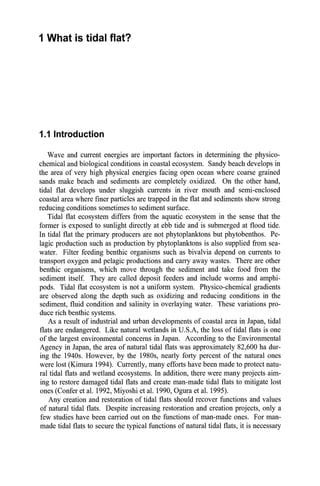
The study sites were selected in the northern part of Hiroshima Bay, which is
located in the western part of the Seto-Inland Sea, Japan (Fig. 1.1). The Ohta
River flows into the northern part of this bay. Table 1.1 summarized characteristic
features of natural and man-made tidal flats. Man-made tidal flats were con-
structed for various purposes like oyster and clam cultures, bathing resort and
compensatory mitigation. The significant difference in water quality in the north-
ern part of Hiroshima Bay was not observed: DO (dissolved oxygen) and COD
(chemical oxygen demand) at S1.2 located at the middle of the bay and S1.8 lo-
cated at the back of the bay ranged from 10.7 to 12.4 mg r1
and from 0.9 to 1.2
mg r1
, respectively (Maritime Safety Agency 1997). It was presumed that the wa-
ter quality in the northern part of the bay and, offshore of all the tidal flats was al-
most the same.
o Natural tidal flat
• Man-made tidal flat
Fig. 1.1. Location ofthe studied tidal flats in Hiroshima bay
17.
1.2 Function andstructure ofnatural and man-made tidal flats 3
Table 1.1. The studied tidal flats in Hiroshima bay
Site Origin Area (ha) Slope
Constructed
Purpose
year
St.l Natural 24 1.0/100
St.2 Natural 4.7 1.0/100
S1.3 Natural 3.3 1.6/100
St.4 Man-made 24 2.5/100 1990
Compensatory
mitigation
St.5 Man-made 3.2 0.4/100 1986 Oyster culture
St.6 Man-made 6.7 0.7/100 1973 Oyster culture
St.7 Man-made 1.2 1.5/100 1984 Clam culture
St.8 Man-made 5.0 2.0/100 1987 Clam culture
St.9 Man-made 2.3 4.0/100 1987 Bathing resort
St.lO Man-made 2.3 0.7/100 1987 Oyster culture
Table 1.2. Physico-chemical characteristics ofsediment in the tidal flats
Site Origin
Mean me- Silt Carbon Nitrogen Reducing
dium(mm) (%) (mg g_dry-l) (mg g_dry-l) zone (cm)
St.l Natural 0.49 4.77 10.25 0.93 -2
St.2 Natural 0.39 2.71 3.30 0.33 -2
St.3 Natural 0.57 8.68 5.28 0.52 -2
St.4 Man-made 1.60 0.03 1.50 0.07 ND
St.5 Man-made 0.88 0.85 1.28 0.13 -25
St.6 Man-made 0.42 0.35 1.52 0.10 -15
St.7 Man-made 0.49 0.50 2.08 0.23 -20
St.8 Man-made 0.40 0.87 0.90 0.10 ND
St.9 Man-made 0.80 0.05 1.09 0.10 ND
St.lO Man-made 0.46 2.78 3.78 0.30 -2
Reducing zone: soil depth from the surface showing minus potential.
ND: reducing zone was not detected within core sample of 30 em.
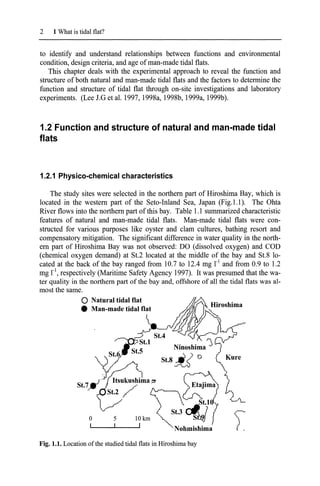
Fig.l.2 shows vertical profiles ofparticle size distribution of soils in the typical
natural (St.2) and man-made (St.8) tidal flats. Median particle diameters in the
natural tidal flat were 0.6 mm in the surface (0 ~ 2 cm) and 0.28 ~ 0.42 mm under
2cm-depth. Median particle diameters in the man-made tidal flat were 0.26 ~ 0.38
mm through all depths. There is no significant difference between the two tidal
flats with respect to the median particle diameter. However, silt content indicated
large difference between the tidal flats. The natural tidal flat had larger amount of
silt (3.5 ~ 6.6 %) compared with the man-made tidal flat (0.4 ~ 1.6 %). The con-
tents of silt for all tidal flats studied are given in Table 1.2. The silt contents in the
natural tidal flats were higher than those in the man-made tidal flats except St.lO.
The silt content at St.lO was the highest among the man-made tidal flats and was
almost the same as those in the natural ones. The organic carbon content of soil
18.
4 1 Whatis tidal flat?
was in the range of 3.30 to 10.25 mgC g-I in the natural tidal flats and 0.90 to 3.78
mgC g-l in the man-made ones. The organic carbon at SUO was 3.78 mgC ii,
which was also the highest among the man-made ones and was also similar to
those in the natural ones.
3lUrailidai nat (SI.2) Man-made tidal n", ($1.8)
10._0P======r:::==~
•
"-
5 I- •
I•..,.
'.
5 .-
0·5 !1-----------J------I
5- 10f-'---------.......- ............-I
0.8
0.4 0.6
Dry weighl
0.2
o
20-30t::::::===========~
0.4 0.6 0.8
Dry eighl
0.2
o
20-2
15-2
0·2
2-5
.[ 5·1
.c
E.
Q 10·1
Fig. 1.2. Vertical profiles of particle size distribution of soils in natural and man-
made tidal flats. Pebble: >4.75mm, Fine pebble: 2.00~4.75 mm, Coarse sand:
0.425~2.00 mm, Fine sand: O.075~0.425 mm, Silt+sand: O~O.075 mm
400
300
200
100
Eh (mV)
o
-100
-0- Natural tidal flat (St.2)
'-:-:::--:-=-::-::---e----------<
-e- Man-made tidal flat (St.8)
0
5
E 10
~
..<::
c..
0)
15
Cl
20
25
-200
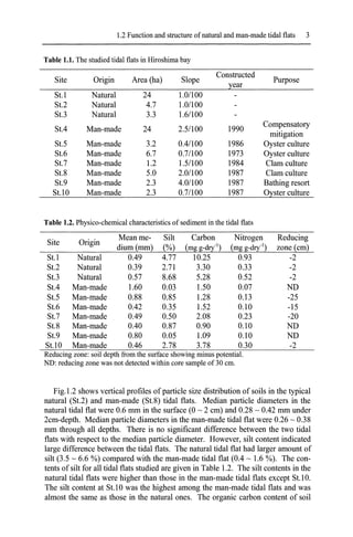
Fig. 1.3. Vertical profiles ofORP in soils ofnatural and man-made tidal flats
19.
1.2 Function andstructure ofnatural and man-made tidal flats 5
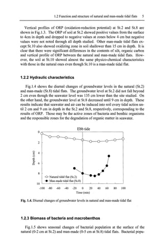
Vertical profiles of ORP (oxidation-reduction potential) at St.2 and St.8 are
shown in Fig.l.3. The ORP of soil at St.2 showed positive values from the surface
to 4cm in depth and dropped to negative values at zones below 4 cm but negative
values were not noted through all depth studied. Other man-made tidal flats ex-
cept St.l0 also showed oxidizing zone in soil shallower than 15 cm in depth. It is
clear that there were significant differences in the contents of silt, organic carbon
and vertical profile of ORP between the natural and man-made tidal flats. How-
ever, the soil at St.10 showed almost the same physico-chemical characteristics
with those in the natural ones even though St.l0 is a man-made tidal flat.
1.2.2 Hydraulic characteristics
Fig.l.4 shows the diurnal changes of groundwater levels in the natural (St.2)
and man-made (St.8) tidal flats. The groundwater level at St.2 did not fall beyond
2 cm even though the seawater level was 135 cm lower than the site studied. On
the other hand, the groundwater level at St.8 decreased until 9 cm in depth. These
results indicate that seawater and air can be induced into soil every tidal action un-
til 2 cm and 9 cm in depth in the St.2 and St.8, respectively, corresponding to the
results ofORP. Those may be the active zones of bacteria and benthic organisms
and the responsible zones for the degradation of organic matter in seawater.
Ebb tide
O~-------------r--------------,
2
8
-0- Natural tidal flat (St.2)
.... Man-made tidal flat (St.8)
10 '------'---'-------'----'---'-----'----'----'------'------'
-100 -80 -60 -40 -20 0 20 40 60 80 100
Time (min)
Fig. 1.4. Diurnal changes ofgroundwater levels in natural and man-made tidal flat
1.2.3 Biomass of bacteria and macrobenthos
Fig.l.S shows seasonal changes of bacterial population at the surface of the
natural (0-2 cm at St.2) and man-made (0-5 cm at St.8) tidal flats. Bacterial popu-
20.
6 1 Whatis tidal flat?
lation in soils of the natural tidal flat ranged from 1.6 to 3.6 x 10⁹
cells g_dry-l but
seasonal change was not observed. Similar result was obtained for bacterial popu-
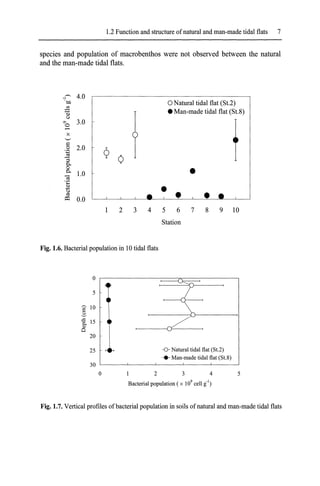
lation at the man-made tidal flat. Fig.l.6 shows bacterial populations at the surface
of soil in 10 tidal flats. Bacterial populations ranged from 1.6 to 2.5 x 10⁹
cells g-
dry-' in the natural tidal flats while the populations in the man-made tidal flats
were in the range ofO.O? to 0.38 x 10⁹
cells g_dry-l except for SUO. The bacterial
population in soil of the man-made tidal flat was one to two orders of magnitude
lower than in soil of the natural one. However, the population at St.l0 was 2.3 x
109
cells g-dry-'. This was the highest among the samples collected from the man-
made tidal flats and was similar to those in the natural tidal flats. Fig.1.? shows
vertical profiles of bacterial population in soils at St.2 and St.8. The bacterial
populations did not change by depth at both tidal flats. Organic carbon supplied
from seawater must be different between infiltration and non-infiltration zones
that were from the surface to 2 cm in depth and below 2 cm at St.2, and the sur-
face to 9 cm and below 9 cm at St.8, respectively. Results indicate that bacterial
population is independent of organic carbon supplied.
-0- Natural tidal flat (81.2)
... Man-made tidal flat (81.8)
..-.-.-.. .-. •• .~
S",oQ. ~o" '1>"" ~~ ~'1>'" ~ S",oQ. ~o" '1>""
1994 1995 1996
Fig. 1.5. Seasonal change ofbacterial population in natural and man-made tidal flats-
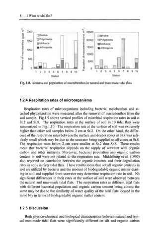
Fig.1.8 shows the biomass (as wet weight) and population of macrobenthos in
the natural and man-made tidal flats. No remarkable difference between the natu-
ral and man-made ones was noted in the biomass. The percentages of bivalve to
total biomass were extremely high at St.7 and St.8 due to artificial introduction of
clam (principally Ruditapes philippinarum). Havens et al. (1995) reported that the
biomass of macrobenthos in two natural tidal marshes and a man-made one were
nearly the same and an apparent difference could not be found among them. The
predominant species of macrobenthos in both tidal flats was Polychaeta. At SUO,
however, Mollusca was the predominant species. Significant differences in both
21.
1.2 Function andstructure ofnatural and man-made tidal flats 7
species and population of macrobenthos were not observed between the natural
and the man-made tidal flats.
~
4.0
OJ)
oNatural tidal flat (St.2)
$;I
• Man-made tidal flat (St.8)
a>
u
'" 3.0
t
0
-
x
'-'
~
2.0
.8
¢
~
Q
'3
0..
0
•
0..
1.0
<a
.;::
Il)
.....
u
ro
o:l 0.0
2 3 4 5 6 7 8 9 10
Station
Fig. 1.6. Bacterial population in 10 tidal flats
o
5
~ 10
t 15
~
20
25 -0- Natural tidal flat (St.2)
... Man-made tidal flat (St.8)
5
1 2 3 4
Bacterial population (x 109
cell gO')
30 '------'-------'------'------'------'
o
Fig. 1.7. Vertical profiles ofbacterial population in soils ofnatural and man-made tidal flats
22.
8 1 Whatis tidal flat?
.;-- ":'
E 2000 E 25000
~ oBivalve -0 oBivalve
c
,S!J
oPolychaeta =
I/)
1500 I/)
20000 ~ Polychaeta
0
0
• Mollusca £;
.t::
Mollusca
C c
Ql
• Arthropoda
Ql
15000
~
~
• Arthropoda
e 1000 e
u u
'"
'" E 10000
E 7
'0 500 ~
'0
I/) c:
I/) 0 5000
'" '" ~
E ~ "5
0 Q.
iii 0 0 0
a. 8 9 10
1 2 3 4 5 6 7 8 9 10
Station Station
Fig. 1.8. Biomass and population ofmacrobenthos in natural and man-made tidal flats
1.2.4 Respiration rates of microorganisms
Respiration rates of microorganisms including bacteria, meiobenthos and at-
tached phytoplankton were measured after the removal of macrobenthos from the
soil sample. Fig.I.9 shows vertical profiles of microbial respiration rates in soil at
St.2 and St.8. The respiration rates at the surface of soil in 10 tidal flats were
summarized in Fig.l.lO. The respiration rate at the surface of soil was extremely
higher than other soil samples below 2 cm at St.2. On the other hand, the differ-
ence of the respiration rates between the surface and deeper zones at St.8 was rela-
tively small which may be due to the seawater being supplied to all zones at St.8.
The respiration rates below 2 cm were smaller at St.2 than St.8. These results
mean that bacterial respiration depends on the supply of seawater with organic
carbon and other nutrients. Moreover, bacterial population and organic carbon
content in soil were not related to the respiration rate. Middelburg et al. (1996)
also reported no correlation between the organic contents and their degradation
rates in soils in river tidal flats. These results mean that not all organic contents in
soil are utilized by bacteria and the amount of biodegradable organic matter exist-
ing in soil and supplied from seawater may determine respiration rate in soil. No
significant differences in their rates at the surface of soil were observed between
the natural and man-made tidal flats. The respiration rates at different tidal flats
with different bacterial population and organic carbon content being almost the
same may be due to the similarity of water quality of the tidal flats located in the
same bay in terms ofbiodegradable organic matter content.
1.2.5 Discussion
Both physico-chemical and biological characteristics between natural and typi-
cal man-made tidal flats were significantly different on silt and organic carbon
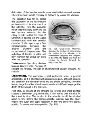
performed by simpledepression of the lens backwards into the vitreous
with a needle passed through the cornea (anterior route). This operation
yields unsatisfactory results owing to the lens being liable to return into
the pupil; this can be partly overcome by sweeping the needle round the
periphery of the lens so as to divide the suspensory ligament, but the
operation is not so satisfactory as when the needle is passed in from
behind the ciliary body and the lens pressed down from behind
(posterior route), to which the following description applies. The capsule
of the lens should be torn freely, so that some absorption may
subsequently take place and diminish the risk of complications.
Instruments. Speculum, fixation forceps, needle.
First step. The pupil should be dilated with atropine. The patient’s head
should be well raised on the table. The needle is passed through the
sclerotic about 5 millimetres behind the limbus to the outer side. The
posterior capsule of the lens is then freely divided by a sweeping
movement.
Second step. The needle is next made to appear in the lower part of the
pupil by carrying it round the lower and outer border of the lens. The
anterior capsule is then freely divided.
Third step. The shaft of the needle is laid flat on the surface of the lens
towards its upper part, and by raising the handle of the needle the lens
is displaced backwards into the vitreous. The tearing of the suspensory
ligament on the inner side may be assisted by the cutting edge of the
needle during depression.
Complications. Immediate. Difficulty may be experienced in
making the lens lie at the bottom of the vitreous, and it is only by
frequent depression of the lens backwards and downwards, with a
sweeping movement of the needle to divide the suspensory ligament,
that the desired effect can be obtained.
Remote. The lens nucleus may prolapse through the pupil into the
anterior chamber. If this should happen, the patient should be placed on
his back and the pupil dilated with atropine; if the nucleus does not go
back into the vitreous chamber it should be depressed by means of a
needle passed through the cornea.
25.
Glaucoma may resultfrom the dislocation of the nucleus into the
anterior chamber and should be treated as described above. It may also
be present with a lens which is dislocated backwards. This condition is
very liable to end in loss of sight. Probably the only hope of relieving the
tension is by the use of eserine or the performance of a cyclo-dialysis.
Cyclitis and retinal detachment may also follow, and usually end in
blindness.
CHAPTER III
OPERATIONS UPON THE IRIS
IRIDOTOMY
Indications. Iridotomy is an operation which is performed when
the iris has become drawn up after a cataract extraction, so that there is
no pupil, or the pupillary area is covered by the upper lid. A long interval
should elapse between the extraction and the iridotomy, since these
cases have usually suffered from cyclitis following the operation.
Iridotomy should not be performed for at least six months after all signs
of cyclitis have disappeared, for the frequent failure of the operation is
due to the fact that the opening made in the iris and underlying capsule
becomes filled with fibrous exudation as the result of cyclitis, which is
frequently set up again by the operation if undertaken before a sufficient
time has elapsed for the eye to settle down after the inflammation. The
ideal operation, therefore, is to make an artificial pupil with the least
amount of trauma to the ciliary body.
Instruments. Speculum; fixation forceps; a long, narrow, bent ‘broad
needle’; Tyrrell’s hook, iris scissors, iris forceps, and spatula.
Operation. Many operations have been devised for this most
troublesome condition, but the following is the one that the author has
found to be successful.
26.
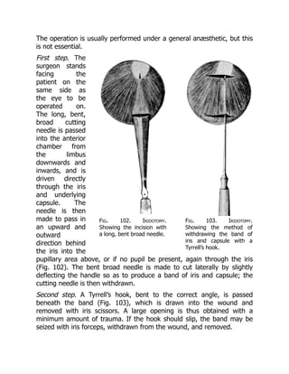
Fig. 102. Iridotomy.
Showingthe incision with
a long, bent broad needle.
Fig. 103. Iridotomy.
Showing the method of
withdrawing the band of
iris and capsule with a
Tyrrell’s hook.
The operation is usually performed under a general anæsthetic, but this
is not essential.
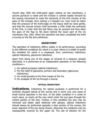
First step. The
surgeon stands
facing the
patient on the
same side as
the eye to be
operated on.
The long, bent,
broad cutting
needle is passed
into the anterior
chamber from
the limbus
downwards and
inwards, and is
driven directly
through the iris
and underlying
capsule. The
needle is then
made to pass in
an upward and
outward
direction behind
the iris into the
pupillary area above, or if no pupil be present, again through the iris
(Fig. 102). The bent broad needle is made to cut laterally by slightly
deflecting the handle so as to produce a band of iris and capsule; the
cutting needle is then withdrawn.
Second step. A Tyrrell’s hook, bent to the correct angle, is passed
beneath the band (Fig. 103), which is drawn into the wound and
removed with iris scissors. A large opening is thus obtained with a
minimum amount of trauma. If the hook should slip, the band may be
seized with iris forceps, withdrawn from the wound, and removed.
27.
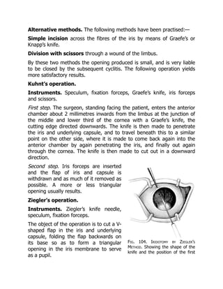
Fig. 104. Iridotomyby Ziegler’s
Method. Showing the shape of the
knife and the position of the first
Alternative methods. The following methods have been practised:—
Simple incision across the fibres of the iris by means of Graefe’s or
Knapp’s knife.
Division with scissors through a wound of the limbus.
By these two methods the opening produced is small, and is very liable
to be closed by the subsequent cyclitis. The following operation yields
more satisfactory results.
Kuhnt’s operation.
Instruments. Speculum, fixation forceps, Graefe’s knife, iris forceps
and scissors.
First step. The surgeon, standing facing the patient, enters the anterior
chamber about 2 millimetres inwards from the limbus at the junction of
the middle and lower third of the cornea with a Graefe’s knife, the
cutting edge directed downwards. The knife is then made to penetrate
the iris and underlying capsule, and to travel beneath this to a similar
point on the other side, where it is made to come back again into the
anterior chamber by again penetrating the iris, and finally out again
through the cornea. The knife is then made to cut out in a downward
direction.
Second step. Iris forceps are inserted
and the flap of iris and capsule is
withdrawn and as much of it removed as
possible. A more or less triangular
opening usually results.
Ziegler’s operation.
Instruments. Ziegler’s knife needle,
speculum, fixation forceps.
The object of the operation is to cut a V-
shaped flap in the iris and underlying
capsule, folding the flap backwards on
its base so as to form a triangular
opening in the iris membrane to serve
as a pupil.
28.
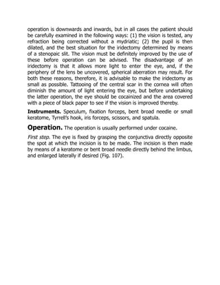
puncture in theiris; the cutting is
performed by a sawing movement.
First step. The knife needle is entered at
the corneo-sclerotic junction with the
blade turned on the flat and is passed
completely across the anterior chamber to within 3 mm. of the apparent
iris periphery. The knife is then turned edge downwards, and carried 3
mm. to the left of the vertical plane (Fig. 104).
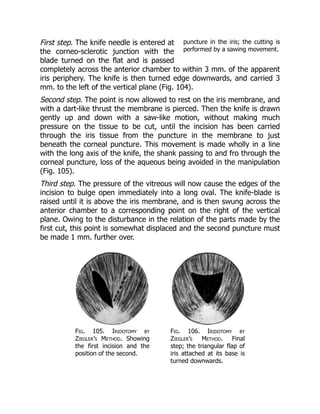
Second step. The point is now allowed to rest on the iris membrane, and
with a dart-like thrust the membrane is pierced. Then the knife is drawn
gently up and down with a saw-like motion, without making much
pressure on the tissue to be cut, until the incision has been carried
through the iris tissue from the puncture in the membrane to just
beneath the corneal puncture. This movement is made wholly in a line
with the long axis of the knife, the shank passing to and fro through the
corneal puncture, loss of the aqueous being avoided in the manipulation
(Fig. 105).
Third step. The pressure of the vitreous will now cause the edges of the
incision to bulge open immediately into a long oval. The knife-blade is
raised until it is above the iris membrane, and is then swung across the
anterior chamber to a corresponding point on the right of the vertical
plane. Owing to the disturbance in the relation of the parts made by the
first cut, this point is somewhat displaced and the second puncture must
be made 1 mm. further over.
Fig. 105. Iridotomy by
Ziegler’s Method. Showing
the first incision and the
position of the second.
Fig. 106. Iridotomy by
Ziegler’s Method. Final
step; the triangular flap of
iris attached at its base is
turned downwards.
29.
Fourth step. Withthe knife-point again resting on the membrane, a
second puncture is made and the incision is carried rapidly forward by
the sawing movement to meet the extremity of the first incision at the
apex of the triangle, thus making a V-shaped cut. Care must be taken
that the pressure of the knife-edge on the tissue shall be most gentle,
and that the second incision shall terminate a trifle inside the extremity
of the first, in order that the last fibres may be severed and thus allow
the apex of the flap to fall down behind the lower part of the iris
membrane (Fig. 106). When the operation has been completed the knife
is turned on the flat and withdrawn.
IRIDECTOMY
The operation of iridectomy differs widely in its performance, according
to the different conditions for which it is used. Hence it is better to prefix
the condition for which it is employed, thus: preliminary iridectomy,
optical iridectomy, glaucoma iridectomy.
Apart from being one of the stages of removal of a cataract, already
described, it is performed as an independent operation in the following
conditions:—
1. For optical purposes (optical iridectomy).
2. For the relief of glaucoma, primary and secondary (glaucoma
iridectomy).
3. For small growths at the free margin of the iris.
4. For prolapse of the iris through a wound.
OPTICAL IRIDECTOMY
Indications. Iridectomy for optical purposes is performed for a
centrally situated nebula of the cornea and in some very rare cases of
small central opacities in the lens. In the latter condition it is rarely of
much value, as nearly all the rays which enter the eye pass through the
central portion of the lens. Further, in this condition the lens may be
removed and better sight obtained with glasses. Optical iridectomy
should always be performed opposite a clear portion of the cornea, the
lower segment of the eye being chosen, otherwise the coloboma may be
subsequently covered by the upper lid. The site of election for the
30.
operation is downwardsand inwards, but in all cases the patient should
be carefully examined in the following ways: (1) the vision is tested, any
refraction being corrected without a mydriatic; (2) the pupil is then
dilated, and the best situation for the iridectomy determined by means
of a stenopaic slit. The vision must be definitely improved by the use of
these before operation can be advised. The disadvantage of an
iridectomy is that it allows more light to enter the eye, and, if the
periphery of the lens be uncovered, spherical aberration may result. For
both these reasons, therefore, it is advisable to make the iridectomy as
small as possible. Tattooing of the central scar in the cornea will often
diminish the amount of light entering the eye, but before undertaking
the latter operation, the eye should be cocainized and the area covered
with a piece of black paper to see if the vision is improved thereby.
Instruments. Speculum, fixation forceps, bent broad needle or small
keratome, Tyrrell’s hook, iris forceps, scissors, and spatula.
Operation. The operation is usually performed under cocaine.
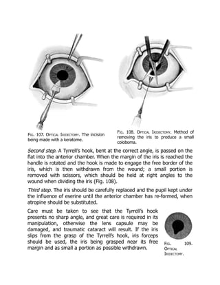
First step. The eye is fixed by grasping the conjunctiva directly opposite
the spot at which the incision is to be made. The incision is then made
by means of a keratome or bent broad needle directly behind the limbus,
and enlarged laterally if desired (Fig. 107).
31.
Fig. 109.
Optical
Iridectomy.
Fig. 107.Optical Iridectomy. The incision
being made with a keratome.
Fig. 108. Optical Iridectomy. Method of
removing the iris to produce a small
coloboma.
Second step. A Tyrrell’s hook, bent at the correct angle, is passed on the
flat into the anterior chamber. When the margin of the iris is reached the
handle is rotated and the hook is made to engage the free border of the
iris, which is then withdrawn from the wound; a small portion is
removed with scissors, which should be held at right angles to the
wound when dividing the iris (Fig. 108).
Third step. The iris should be carefully replaced and the pupil kept under
the influence of eserine until the anterior chamber has re-formed, when
atropine should be substituted.
Care must be taken to see that the Tyrrell’s hook
presents no sharp angle, and great care is required in its
manipulation, otherwise the lens capsule may be
damaged, and traumatic cataract will result. If the iris
slips from the grasp of the Tyrrell’s hook, iris forceps
should be used, the iris being grasped near its free
margin and as small a portion as possible withdrawn.
32.
Showing the
coloboma.
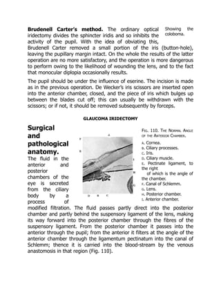
Fig. 110.The Normal Angle
of the Anterior Chamber.
a. Cornea.
b. Ciliary processes.
c. Iris.
d. Ciliary muscle.
e. Pectinate ligament, to
the right
of which is the angle of
the chamber.
f. Canal of Schlemm.
g. Lens.
h. Posterior chamber.
i. Anterior chamber.
Brudenell Carter’s method. The ordinary optical
iridectomy divides the sphincter iridis and so inhibits the
activity of the pupil. With the idea of obviating this,
Brudenell Carter removed a small portion of the iris (button-hole),
leaving the pupillary margin intact. On the whole the results of the latter
operation are no more satisfactory, and the operation is more dangerous
to perform owing to the likelihood of wounding the lens, and to the fact
that monocular diplopia occasionally results.
The pupil should be under the influence of eserine. The incision is made
as in the previous operation. De Wecker’s iris scissors are inserted open
into the anterior chamber, closed, and the piece of iris which bulges up
between the blades cut off; this can usually be withdrawn with the
scissors; or if not, it should be removed subsequently by forceps.
GLAUCOMA IRIDECTOMY
Surgical
and
pathological
anatomy.
The fluid in the
anterior and
posterior
chambers of the
eye is secreted
from the ciliary
body by a
process of
modified filtration. The fluid passes partly direct into the posterior
chamber and partly behind the suspensory ligament of the lens, making
its way forward into the posterior chamber through the fibres of the
suspensory ligament. From the posterior chamber it passes into the
anterior through the pupil; from the anterior it filters at the angle of the
anterior chamber through the ligamentum pectinatum into the canal of
Schlemm; thence it is carried into the blood-stream by the venous
anastomosis in that region (Fig. 110).
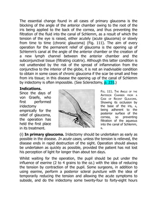
33.
Fig. 111. TheAngle of the
Anterior Chamber from a
Case of Recent Glaucoma.
Showing its occlusion by
the base of the iris, a,
being adherent to the
posterior surface of the
cornea, so preventing
filtration of the aqueous
into the canal of Schlemm,
b.
The essential change found in all cases of primary glaucoma is the
blocking of the angle of the anterior chamber owing to the root of the
iris being applied to the back of the cornea, and thus preventing the
filtration of the fluid into the canal of Schlemm, as a result of which the
tension of the eye is raised, either acutely (acute glaucoma) or slowly
from time to time (chronic glaucoma) (Fig. 111). The aim of every
operation for the permanent relief of glaucoma is the opening up of
Schlemm’s canal at the angle of the anterior chamber or the creation of
a new lymph channel between the anterior chamber and the
subconjunctival tissue (filtrating cicatrix). Although this latter condition is
not unattended by the risk of the spread of inflammation from the
conjunctiva to the interior of the globe, it is not an inadvisable condition
to obtain in some cases of chronic glaucoma if the scar be small and free
from iris tissue; in this disease the opening up of the canal of Schlemm
by iridectomy is often impossible. (See Sclerectomy, p. 231.)
Indications.
Since the days of
von Graefe, who
first performed
iridectomy
empirically for the
relief of glaucoma,
the operation has
held the first place
in its treatment.
(i) In primary glaucoma. Iridectomy should be undertaken as early as
possible in the disease. In acute cases, unless the tension is relieved, the
disease ends in rapid destruction of the sight. Operation should always
be undertaken as quickly as possible, provided the patient has not lost
his perception of light for longer than about ten days.
Whilst waiting for the operation, the pupil should be put under the
influence of eserine (2 to 4 grains to the oz.) with the idea of reducing
the tension by contraction of the pupil. Some surgeons, in addition to
using eserine, perform a posterior scleral puncture with the idea of
temporarily reducing the tension and allowing the acute symptoms to
subside, and do the iridectomy some twenty-four to forty-eight hours
34.
later. This methodis extremely useful (a) in cases where a general
anæsthetic is inadvisable, since the reduction of tension allows cocaine
to diffuse into the eye; (b) in cases liable to subsequent intra-ocular
hæmorrhage, a more gradual reduction of tension being obtained,
rupture of a choroidal vessel is less likely to occur; (c) a deeper anterior
chamber is often obtained, and hence there is less risk of wounding the
lens during the operation; (d) in cases where the operation has been
performed in one eye and the lens has been subsequently extruded on
the dressings.
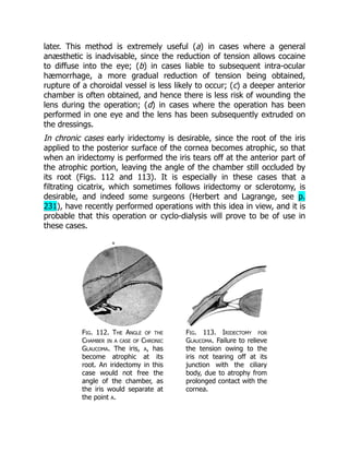
In chronic cases early iridectomy is desirable, since the root of the iris
applied to the posterior surface of the cornea becomes atrophic, so that
when an iridectomy is performed the iris tears off at the anterior part of
the atrophic portion, leaving the angle of the chamber still occluded by
its root (Figs. 112 and 113). It is especially in these cases that a
filtrating cicatrix, which sometimes follows iridectomy or sclerotomy, is
desirable, and indeed some surgeons (Herbert and Lagrange, see p.
231), have recently performed operations with this idea in view, and it is
probable that this operation or cyclo-dialysis will prove to be of use in
these cases.
Fig. 112. The Angle of the
Chamber in a case of Chronic
Glaucoma. The iris, a, has
become atrophic at its
root. An iridectomy in this
case would not free the
angle of the chamber, as
the iris would separate at
the point a.
Fig. 113. Iridectomy for
Glaucoma. Failure to relieve
the tension owing to the
iris not tearing off at its
junction with the ciliary
body, due to atrophy from
prolonged contact with the
cornea.
35.
Operation is onlycontra-indicated in a few very rare cases in which the
tension is controlled by the use of eserine.
(ii) In congenital glaucoma (bup[h]thalmos). In this affection the
results of iridectomy vary. Without doubt, the tension has been relieved
by iridectomy in some cases, and either this operation, sclerectomy, or
cyclo-dialysis should be tried if the disease be not too far advanced.
(iii) In secondary glaucoma. For obvious reasons the predisposing
causes should always be taken into consideration. Thus it would be of no
use to perform an iridectomy in the case of a growth in the choroid. On
the other hand, an iridectomy would be unjustifiable for soft lens matter
in the anterior chamber, which merely requires evacuation. An early
iridectomy in cyclitis is not likely to influence the course of the disease
favourably; at the most a paracentesis is required. As the early stages of
cyclitis may give rise to tension, it is essential that every case of
glaucoma should be examined for keratitis punctata before operation.
In iris bombé and total posterior synechiæ an iridectomy is indicated
more to re-establish the communication between the anterior and
posterior chambers than to clear the angle, and therefore it need not be
so extensive. In cases of iris bombé where iritis is still present, and in
cases of cysts of the iris, transfixion is all that is necessary.
It is very doubtful if iridectomy in glaucoma following thrombosis of the
central vein is justifiable, for as a rule the tension is not permanently
relieved thereby. In secondary glaucoma following cataract extraction or
anterior synechiæ, division of the capsule or the anterior synechiæ will
often relieve the tension.
Instruments. Speculum, fixation forceps, Graefe’s knife (with a short,
stiff, narrow blade), iris forceps, scissors, and spatula.
Operation. With the idea of opening up the angle of the anterior
chamber by removing the iris as near its root as possible, the incision
should be made somewhat further back behind the corneo-sclerotic
junction than in cataract extraction. At the same time, if the incision be
placed too far back the ciliary body is liable to prolapse into the wound.
The old idea of opening up the canal of Schlemm by dividing it has been
abandoned, as to do so would certainly result in prolapse of the ciliary
36.
body; and evenif this did not happen, no good would result, since the
canal would become closed subsequently by cicatricial tissue.
Although von Graefe used a keratome for making the incision, most
British surgeons of the present day use a Graefe’s knife, as it gives an
incision that is less shelving and more irregular, thus predisposing to the
formation of a filtrating scar; a good conjunctival flap is obtained with it
and there is less risk of wounding the lens.
When performing the iridectomy it is practically impossible to cut the iris
with scissors at its attachment to the ciliary body, and it is better to rely
on tearing it off from the ciliary body, as it is in this situation that the iris
is thinnest and most likely to give way, provided it has not become
atrophic by prolonged contact with the cornea.
In acute cases and in cases of secondary glaucoma where there are
many adhesions a general anæsthetic is desirable.
First step. The incision. The position of the surgeon is as for cataract
extraction. The eye is fixed by grasping the conjunctiva close to the
limbus downwards and inwards. If the patient be under an anæsthetic,
two pairs of fixation forceps should be used, one being held by an
assistant. Occasionally in glaucoma the conjunctiva tears very easily, and
in these cases scleral forceps are of use, or, if the knife be already in the
eye, grasping the insertion of the superior or inferior rectus. The
Graefe’s knife should be directed downwards and inwards towards the
point of fixation, the point being passed through the sclerotic 1.5 mm.
behind the limbus to the outer side. Directly the anterior chamber is
entered, the handle is depressed towards the patient’s chin. The knife-
point is kept superficial to the iris and is passed very slowly across the
anterior chamber, close to its periphery until the position of the counter-
puncture is reached. The counter-puncture should be situated about 1
mm. behind the limbus in a direct line with the original puncture. Care
must be taken in making the counter-puncture that the knife-point does
not slip back on the sclerotic and so emerge further back in the eye than
is desired. The knife is then made to cut out upwards and a good
conjunctival flap is obtained. The incision should be carried out slowly,
so that the aqueous escapes gradually, as sudden reduction in the intra-
ocular tension is liable to lead to intra-ocular hæmorrhage.
37.
Fig. 116. Iridectomyfor
Glaucoma. Division of the
iris to form the inner angle
of the coloboma. The iris is
pulled out as far as
possible before removal.
Fig. 114. Iridectomy for
Glaucoma. Showing the
position in which the iris
should be grasped with
forceps.
Fig. 115. Iridectomy for
Glaucoma. Showing the
irido-dialysis produced
before division.
Second step. The iridectomy. The iris forceps
are inserted closed into the anterior chamber,
opened, and made to grasp the iris near the
periphery (Fig. 114) towards the side of the
wound on which the iris is first to be divided;
then with a slight side-to-side movement of the
forceps the iris is withdrawn from the wound
until its peripheral attachment to the ciliary
body, near where it is held by the forceps, is
felt or seen to give way (irido-dialysis) (Fig.
115). The iris is then drawn a little further out
from the wound, and one side of the dialysis is
divided with the scissors as near the scleral
wound as possible. The iris held in the forceps
is then pulled over to the other angle of the
wound, and as much of it as possible is pulled out and divided close to
the scleral incision (Fig. 116). The angles of the incision are freed from
iris by means of the spatula and the conjunctival flap is replaced in
position. Both eyes are then bandaged.
After-treatment. The patient should be kept in bed for a week,
and during the first four days should not be allowed to raise the head
from the pillow. After that time the eye not operated upon may be
uncovered; eserine should have been instilled into it before the
operation and at subsequent dressings to prevent the possible onset of
38.
glaucoma owing tothe dilatation of the pupil which follows the
application of the bandage to the eye. It is not necessary to use any
mydriatic or myotic for the eye which has been operated upon.
Complications. These may be immediate or remote.
Immediate. 1. In passing a Graefe’s knife into the anterior chamber to
make the section, care must be taken that the cutting edge is directed
upwards. If by accident it should be inserted with the cutting edge
directed downwards the knife should be withdrawn and the operation
postponed for a day or two until the anterior chamber has re-formed.
Care must be taken that the cutting edge is kept on the same plane as
the upper edge of the back of the knife, otherwise the incision is liable
to pass further back than is intended.
2. Splitting the cornea. The anterior chamber often being little more
than a potential space, the knife may be passed between the lamellæ of
the cornea and may not enter the anterior chamber at all. The indication
that the knife-point is not in the anterior chamber is that there is no
diminished resistance, such as is usually felt when the knife enters the
chamber; if its point be slightly depressed, the cornea will be seen to
dimple in over the position of it, showing that the point is not free in the
anterior chamber.
3. Locking of the knife. This is due to the fact that the puncture and
counter-puncture are not made in the same plane, the knife being
twisted. It is much more liable to occur if a knife be chosen with a blade
which is not sufficiently stiff. As a rule the blade can be made to cut out,
but failing this, the knife should be withdrawn sufficiently to allow a
fresh counter-puncture to be made, or else withdrawn altogether and
the operation postponed.
4. Wound of the lens. The great safeguard against wounding the lens is
to keep the point of the knife always superficial to the iris and in the
periphery of the anterior chamber. If the lens be definitely wounded at
the time of the operation it should be extracted immediately after the
iridectomy. If the wound be only subsequently discovered (usually about
the third or fourth day), provided the lens be not presenting in the
wound, the eye should be allowed to settle down and the traumatic
cataract extracted some time after the tenth day.
39.
Fig. 117. Glaucoma
Iridectomy.Failure to
relieve the tension owing
to displacement of the
lens.
5. Presentation of the lens in its capsule. The
lens may present in its capsule at the time of
the operation or be found subsequently on the
dressings. In the latter instance it is very liable
to carry iris into the wound, and a cystoid
cicatrix results. This accident is usually due to
increased tension in the vitreous chamber; a
large incision, especially if placed rather far
back in the sclerotic, will also favour its
occurrence. If the accident should happen to
one eye, and acute glaucoma be present in the other, it is advisable to
do a posterior scleral puncture before the iridectomy is performed.
Partial dislocation of the lens forward may occur after the wound has
healed, leaving the tension of the eye not reduced. This is a condition
extremely difficult to recognize, and it is usually only discovered
pathologically; if recognized clinically, extraction of the lens should be
performed (Fig. 117).
6. Intra-ocular hæmorrhage. Hæmorrhage into the anterior chamber
occurs at the time of the operation and is readily absorbed; occasionally
it may persist for a considerable time in cases of glaucoma of long
standing.
After the operation hæmorrhage may also occur from the cut margin of
the iris, which never heals, viz. never becomes covered with
endothelium. The hæmorrhage may occur as late as two weeks after the
operation and may recur from time to time; it is especially liable to occur
in old people with arterio-sclerosis. It is usually absorbed without giving
rise to any trouble beyond delay in the convalescence.
Retinal hæmorrhages are frequent and usually small, but a considerable
hæmorrhage may take place into the vitreous. As a rule these clear up
satisfactorily unless the macular region be involved.
Subchoroidal hæmorrhage. Of all the immediate complications which
follow an intra-ocular operation this is by far the worst. The
hæmorrhage is due to the giving way of a large choroidal vessel
following the sudden reduction of tension, with the result that the
choroid and retina are stripped up from the sclerotic, and, with the lens,
may be partially extruded from the wound in the globe, from which the
40.
hæmorrhage then proceeds.It may occur whilst the patient is still on
the operating table, or it may be discovered only after he has been put
back to bed, the blood being seen coming through the dressings.
Patients who have this condition complain of pain in the ‘corner of the
eye’ at the time of the operation. The treatment consists in evisceration
or enucleation. It is probable that limited extravasation of blood may
also occur, which need not end in disintegration of the eye, but may
cause vitreous opacity and defective vision for some weeks after the
operation.
Remote. 1. The tension is not reduced by the iridectomy. In acute
cases the prognosis with regard to the reduction of the tension and the
improvement of vision is very satisfactory. The same cannot be said of
chronic cases, especially those which have been operated on rather late
in the disease. If iridectomy, which may be repeated downwards or
extended from the previous coloboma, fail to reduce the tension, one or
more of the following measures should be adopted:—
(a) The use of eserine.
(b) Sclerotomy.
(c) Cyclo-dialysis.
(d) Sclerectomy.
(e) Post-scleral puncture.
It is probably in this order that they should be tried.
2. Prolapse of the iris and irido-cyclitis should be treated as already
indicated under cataract extraction (see p. 208).
3. The onset of glaucoma in the other eye may be induced by the
dilatation of the pupil caused by bandaging, and is best avoided by the
use of eserine. If it should occur, an iridectomy should be performed.
4. Astigmatism produced by the incision is corrected with glasses. This
astigmatism is very marked, often amounting to six or eight diopters or
more.
IRIDECTOMY FOR SMALL GROWTHS OF THE IRIS
Indications. This is performed—
(i) As a diagnostic measure.
41.
(ii) As acurative measure.
In the latter instance it is obvious that the growth must be very small
and situated at the free margin of the iris to yield a satisfactory result,
especially if it be of a malignant character.
Operation. The operation is performed under cocaine, eserine
having been previously instilled in order to contract the pupil.
First step. An incision should be made with a narrow Graefe’s knife in the
limbus in a position most suitable for removing the growth. The incision
should be as large as possible so as to avoid wiping off any portions of
the growth into the anterior chamber.
Second step. The iris should be seized well in the periphery so as to
avoid breaking up the growth; it is then withdrawn with the growth, and
the latter removed.
IRIDECTOMY FOR PROLAPSE OF THE IRIS
This operation is usually performed for prolapse of the iris following a
wound of the cornea or limbus, and may be attempted up to about the
third day after the original injury.
Operation. A general anæsthetic is usually desirable. The prolapsed
iris should be seized with the forceps and withdrawn from the wound. A
second pair of forceps is used to take a fresh hold on the iris, which can
usually be drawn out further (Fig. 118). It is then divided as close to the
corneal wound as possible. The iris usually flies back into the anterior
chamber clear of the corneal wound by its own elasticity, but if it does
not do so it should be freed with a spatula. The pupil should be kept
subsequently under atropine.
42.
Fig. 118. Prolapseof the Iris through a Punctured
Wound of the Cornea. Method of withdrawing the iris
by two pairs of iris forceps before removal.
TRANSFIXION OF THE IRIS
Indications. This operation is undertaken in cases of iris bombé
when iritis is still present and when an iridectomy would
subsequently lead to a drawn-up pupil. It is also of service to
evacuate the contents of cysts of the iris (local iris bombé).
Instruments. Speculum, fixation forceps, Graefe’s knife (narrow).
Operation. The knife is entered at the limbus from the outer
side directly opposite the occluded pupil. The apex of the iris bombé
is transfixed and the point of the knife made to appear above the
pupillary area; the iris bombé on the other side of the pupil is then
transfixed and the knife is withdrawn.
THE DIVISION OF ANTERIOR SYNECHIÆ
Indications. Anterior synechiæ rarely require division unless
they are likely to cause tension or the adherent iris is considered a
source of danger to the eye on account of its liability to septic
infection. If the synechiæ are causing tension, the method of division
described under sclerotomy is probably the most satisfactory;
otherwise the following method devised by Lang can be used.
43.
Instruments. Speculum, fixationforceps, Lang’s knives—one with a
sharp point, and one blunt.
Operation. Under cocaine. The incision is made at the limbus in
a favourable situation for the division of the synechia. The sharp-
pointed knife is introduced into the anterior chamber and then rapidly
withdrawn so as not to lose the aqueous. The blunt knife is then
inserted through the incision and, partly by cutting and partly by
tearing, the synechia is divided in a direction from the periphery
towards the pupil.
The operation is not at all easy to perform, since the iris gives before
the knife. Great care should be taken to avoid evacuating the
aqueous, as the operation is thereby rendered much more difficult or
even impossible.
CHAPTER IV
OPERATIONS UPON THE SCLEROTIC
ANTERIOR SCLEROTOMY
Indications. Sclerotomy is an operation undertaken for the
relief of increased intra-ocular tension. It is performed—
(i) Usually as a secondary operation when iridectomy has failed.
(ii) As a primary operation for the division of anterior synechiæ
causing tension.
A few surgeons prefer the operation to iridectomy, especially in cases
of bup[h]thalmos. When practised after an iridectomy which has
been done upwards, the sclerotomy is sometimes performed in a
downward direction; otherwise the section is usually made upwards.
The intra-ocular tension is probably relieved by the formation of a
44.
filtration cicatrix, andit is therefore probable that it may be largely
superseded by the operations of cyclo-dialysis and sclerectomy.
When performed for the division of anterior synechiæ the position of
the incision should be planned according to the situation of the
synechia to be divided.
Instruments. Speculum, fixation forceps, Graefe’s knife with a
narrow blade.
Operation. The operation is done under cocaine. Eserine should
have been previously instilled in order to contract the pupil and
prevent prolapse of the iris.
Graefe’s knife should be passed across the anterior chamber in the
same manner and position as for a glaucoma iridectomy (see p. 221).
In the complete method the knife is made to cut out through the
sclerotic, leaving a band of conjunctiva to hold the flap in position. In
the incomplete method a band of sclerotic is left in the periphery. If
the operation is done in a downward direction, it is better for the
surgeon to stand on the opposite side of the patient to the eye on
which the operation is to be performed, operating across the patient.
Complications. Any of the complications which follow an iridectomy
for glaucoma may occur (see p. 222). Prolapse of the iris is probably
the most frequent.
CYCLO-DIALYSIS
Indications. This operation has only recently come into general
use in this country, so that statistical results have at present by no
means been worked out, but most satisfactory results have been
obtained from it in individual cases; according to German authorities
about 30 per cent. are permanently cured. Although at present its
performance is largely limited to blind eyes and to eyes that have
undergone previous operations for glaucoma, it is probable that it
may come into further use as a primary operation in the treatment of
chronic glaucoma and bup[h]thalmos. It is also of service in cases of
45.
Fig. 119. Cyclo-dialysisOperation.
Showing the method of commencing
the incision in the sclerotic; it is
subsequently deepened with the point
of the knife. The dotted lines mark the
incision for turning forward the
conjunctival flap.
dislocation of the lens backwards, associated with increased tension,
where iridectomy would certainly be followed by loss of the vitreous.
The operation has for its object
the separation of the ligamentum
pectinatum from its attachment to
the sclerotic, with the probable
result that the ciliary body and iris
root become retracted by the
ciliary muscle, so that the canal of
Schlemm is opened up and again
communicates with the anterior
chamber. It also opens up a free
communication between the
anterior chamber and the
suprachoroidal lymph-spaces. The
reduction of tension is often not
fully manifest for about ten days
after the operation.
Instruments. Speculum, fixation
forceps, Graefe’s knife, fine pair of
straight iris forceps, fine pair of sharp-pointed straight scissors, iris
spatula.
Operation. The operation is best performed under a general
anæsthetic, as it is attended with considerable pain, although cocaine
and adrenalin are frequently used and are always advisable, since the
hæmorrhage from the scleral vessels renders it difficult to gauge the
depth of the wound in the sclerotic.
First step. By means of the straight iris forceps and sharp-pointed
scissors a semilunar conjunctival flap is first raised over the site for
the scleral incision. The incision in the sclerotic should be situated
about 5 mm. behind the corneo-sclerotic junction over the ciliary
region, the outer and upper quadrant of the eye being the easiest
position for subsequent manipulation (Fig. 119).
46.
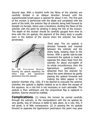
Fig. 120. Cyclo-dialysisOperation.
Showing the spatula separating the
ciliary body and ligamentum
pectinatum from the sclerotic.
Second step. With a Graefe’s knife the fibres of the sclerotic are
carefully divided in an oblique direction forward until the
suprachoroidal lymph-space is opened for about 3 mm. The first part
of the incision is performed with the blade and completed with the
point of the knife, the anterior flap of sclerotic being held forward by
straight iris forceps. Heine uses a keratome, dividing the fibres of the
sclerotic with the point by stroking it along the line of the incision.
The depth of the incision should be carefully gauged from time to
time with the iris spatula; the pigment of the ciliary body is usually
seen in the bottom of the wound when the sclerotic has been
penetrated.
Third step. The iris spatula is
directed forwards and inserted
between the sclerotic and the
ciliary body, keeping close to the
former. With a gentle side-to-side
movement the spatula is made to
separate the ciliary body from the
sclerotic for about one-eighth of
its whole circumference; then the
ligamentum pectinatum is
detached from the sclerotic for
about the same distance by gently
passing the spatula forwards and
making the latter appear in the
anterior chamber (Fig. 120). If it be desired to evacuate the anterior
chamber, the spatula is slightly rotated so as to allow the escape of
the aqueous. As a rule this is not necessary or even advisable. The
spatula is then withdrawn and the conjunctival flap is replaced in
position. Eserine should be instilled.
Complications. (1) Unless the incision be carried carefully
through the sclerotic, or the manipulations with the iris spatula be
very gentle, loss of vitreous is liable to take place. As a rule, this, if
not great, is of little consequence. (2) In passing the iris spatula
forward to separate the ligamentum pectinatum the point may pass
47.
Welcome to ourwebsite – the perfect destination for book lovers and
knowledge seekers. We believe that every book holds a new world,
offering opportunities for learning, discovery, and personal growth.
That’s why we are dedicated to bringing you a diverse collection of
books, ranging from classic literature and specialized publications to
self-development guides and children's books.
More than just a book-buying platform, we strive to be a bridge
connecting you with timeless cultural and intellectual values. With an
elegant, user-friendly interface and a smart search system, you can
quickly find the books that best suit your interests. Additionally,
our special promotions and home delivery services help you save time
and fully enjoy the joy of reading.
Join us on a journey of knowledge exploration, passion nurturing, and
personal growth every day!
ebookbell.com


![Operation is only contra-indicated in a few very rare cases in which the
tension is controlled by the use of eserine.
(ii) In congenital glaucoma (bup[h]thalmos). In this affection the
results of iridectomy vary. Without doubt, the tension has been relieved
by iridectomy in some cases, and either this operation, sclerectomy, or
cyclo-dialysis should be tried if the disease be not too far advanced.
(iii) In secondary glaucoma. For obvious reasons the predisposing
causes should always be taken into consideration. Thus it would be of no
use to perform an iridectomy in the case of a growth in the choroid. On
the other hand, an iridectomy would be unjustifiable for soft lens matter
in the anterior chamber, which merely requires evacuation. An early
iridectomy in cyclitis is not likely to influence the course of the disease
favourably; at the most a paracentesis is required. As the early stages of
cyclitis may give rise to tension, it is essential that every case of
glaucoma should be examined for keratitis punctata before operation.
In iris bombé and total posterior synechiæ an iridectomy is indicated
more to re-establish the communication between the anterior and
posterior chambers than to clear the angle, and therefore it need not be
so extensive. In cases of iris bombé where iritis is still present, and in
cases of cysts of the iris, transfixion is all that is necessary.
It is very doubtful if iridectomy in glaucoma following thrombosis of the
central vein is justifiable, for as a rule the tension is not permanently
relieved thereby. In secondary glaucoma following cataract extraction or
anterior synechiæ, division of the capsule or the anterior synechiæ will
often relieve the tension.
Instruments. Speculum, fixation forceps, Graefe’s knife (with a short,
stiff, narrow blade), iris forceps, scissors, and spatula.
Operation. With the idea of opening up the angle of the anterior
chamber by removing the iris as near its root as possible, the incision
should be made somewhat further back behind the corneo-sclerotic
junction than in cataract extraction. At the same time, if the incision be
placed too far back the ciliary body is liable to prolapse into the wound.
The old idea of opening up the canal of Schlemm by dividing it has been
abandoned, as to do so would certainly result in prolapse of the ciliary](https://image.slidesharecdn.com/2142975-250526153010-b4416df1/85/Waves-And-Tidal-Flat-Ecosystems-1st-Edition-Prof-Eiichi-Baba-35-320.jpg)
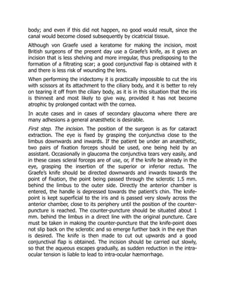
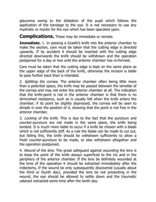
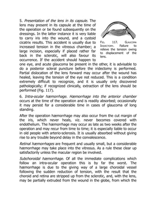
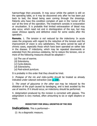
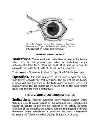
![Instruments. Speculum, fixation forceps, Lang’s knives—one with a
sharp point, and one blunt.
Operation. Under cocaine. The incision is made at the limbus in
a favourable situation for the division of the synechia. The sharp-
pointed knife is introduced into the anterior chamber and then rapidly
withdrawn so as not to lose the aqueous. The blunt knife is then
inserted through the incision and, partly by cutting and partly by
tearing, the synechia is divided in a direction from the periphery
towards the pupil.
The operation is not at all easy to perform, since the iris gives before
the knife. Great care should be taken to avoid evacuating the
aqueous, as the operation is thereby rendered much more difficult or
even impossible.
CHAPTER IV
OPERATIONS UPON THE SCLEROTIC
ANTERIOR SCLEROTOMY
Indications. Sclerotomy is an operation undertaken for the
relief of increased intra-ocular tension. It is performed—
(i) Usually as a secondary operation when iridectomy has failed.
(ii) As a primary operation for the division of anterior synechiæ
causing tension.
A few surgeons prefer the operation to iridectomy, especially in cases
of bup[h]thalmos. When practised after an iridectomy which has
been done upwards, the sclerotomy is sometimes performed in a
downward direction; otherwise the section is usually made upwards.
The intra-ocular tension is probably relieved by the formation of a](https://image.slidesharecdn.com/2142975-250526153010-b4416df1/85/Waves-And-Tidal-Flat-Ecosystems-1st-Edition-Prof-Eiichi-Baba-43-320.jpg)
![filtration cicatrix, and it is therefore probable that it may be largely
superseded by the operations of cyclo-dialysis and sclerectomy.
When performed for the division of anterior synechiæ the position of
the incision should be planned according to the situation of the
synechia to be divided.
Instruments. Speculum, fixation forceps, Graefe’s knife with a
narrow blade.
Operation. The operation is done under cocaine. Eserine should
have been previously instilled in order to contract the pupil and
prevent prolapse of the iris.
Graefe’s knife should be passed across the anterior chamber in the
same manner and position as for a glaucoma iridectomy (see p. 221).
In the complete method the knife is made to cut out through the
sclerotic, leaving a band of conjunctiva to hold the flap in position. In
the incomplete method a band of sclerotic is left in the periphery. If
the operation is done in a downward direction, it is better for the
surgeon to stand on the opposite side of the patient to the eye on
which the operation is to be performed, operating across the patient.
Complications. Any of the complications which follow an iridectomy
for glaucoma may occur (see p. 222). Prolapse of the iris is probably
the most frequent.
CYCLO-DIALYSIS
Indications. This operation has only recently come into general
use in this country, so that statistical results have at present by no
means been worked out, but most satisfactory results have been
obtained from it in individual cases; according to German authorities
about 30 per cent. are permanently cured. Although at present its
performance is largely limited to blind eyes and to eyes that have
undergone previous operations for glaucoma, it is probable that it
may come into further use as a primary operation in the treatment of
chronic glaucoma and bup[h]thalmos. It is also of service in cases of](https://image.slidesharecdn.com/2142975-250526153010-b4416df1/85/Waves-And-Tidal-Flat-Ecosystems-1st-Edition-Prof-Eiichi-Baba-44-320.jpg)