SlideShare a Scribd company logo
1 of 12
Download to read offline
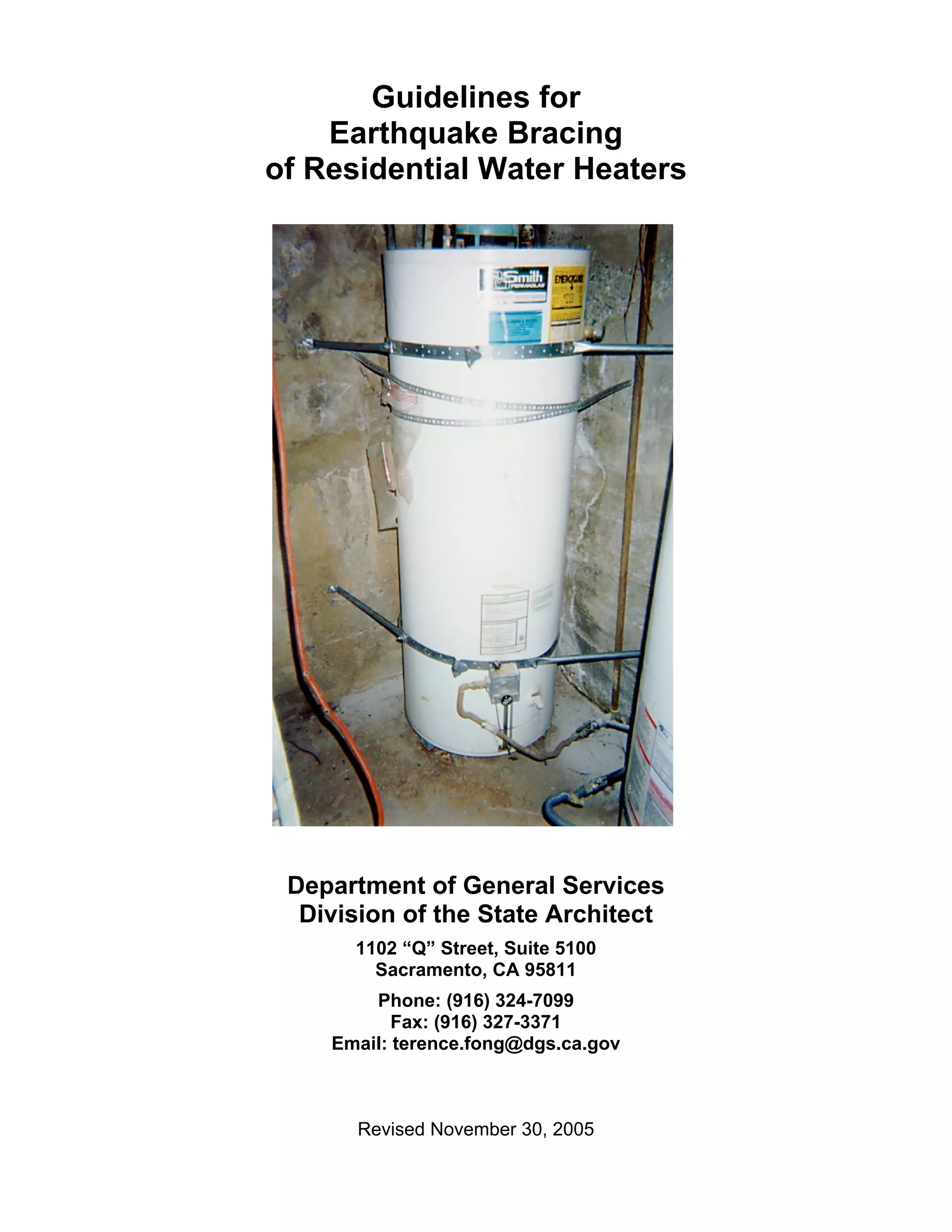
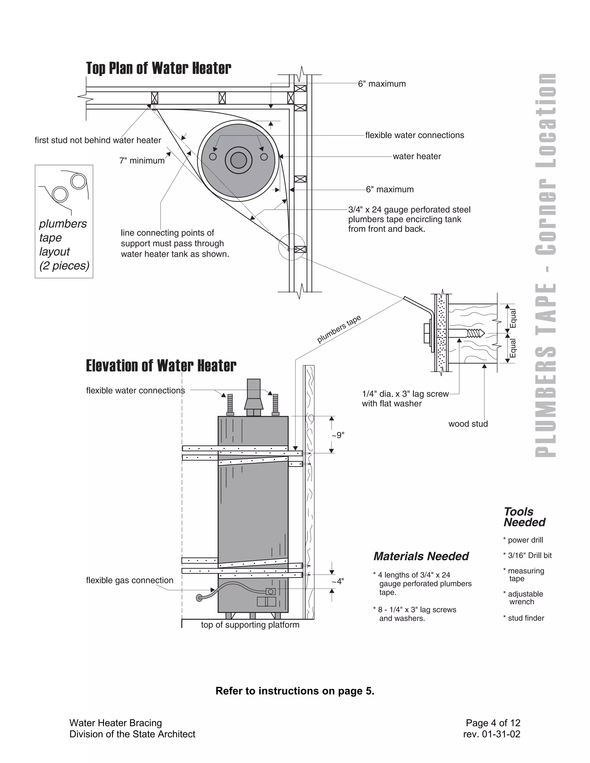
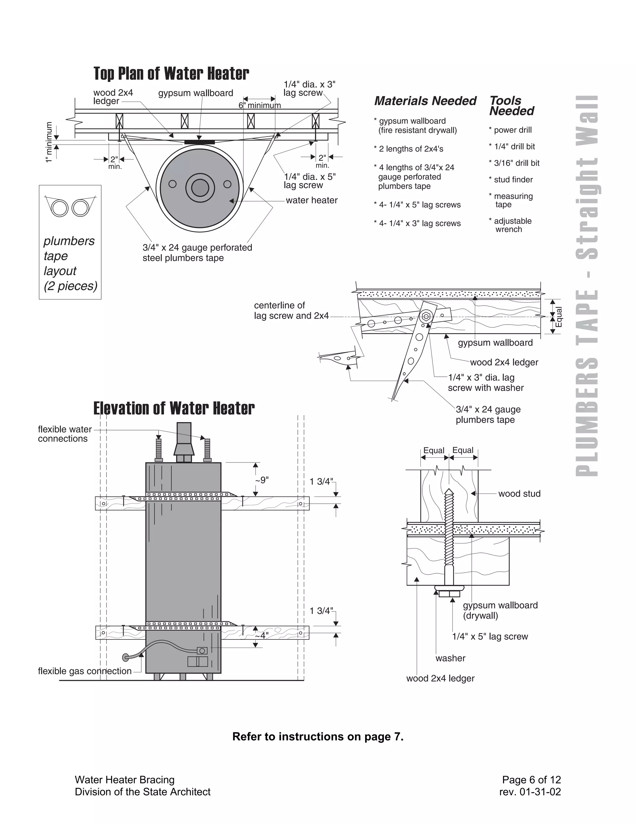
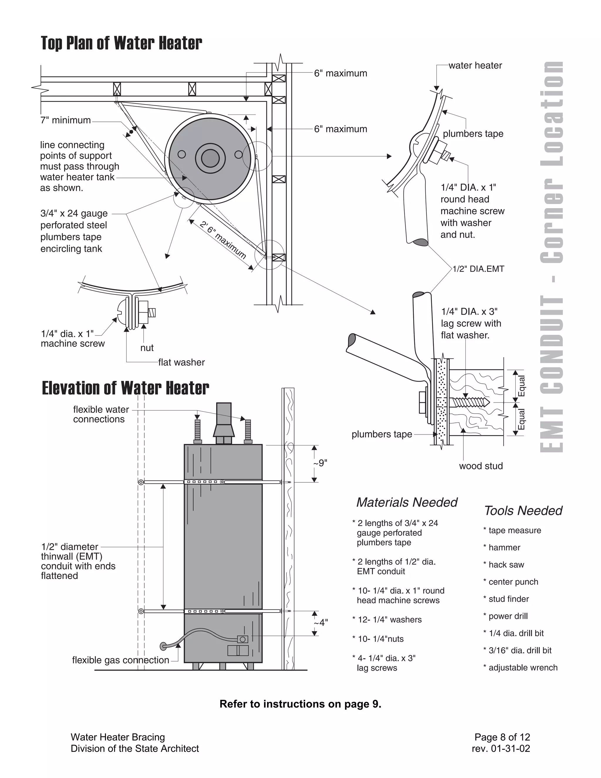
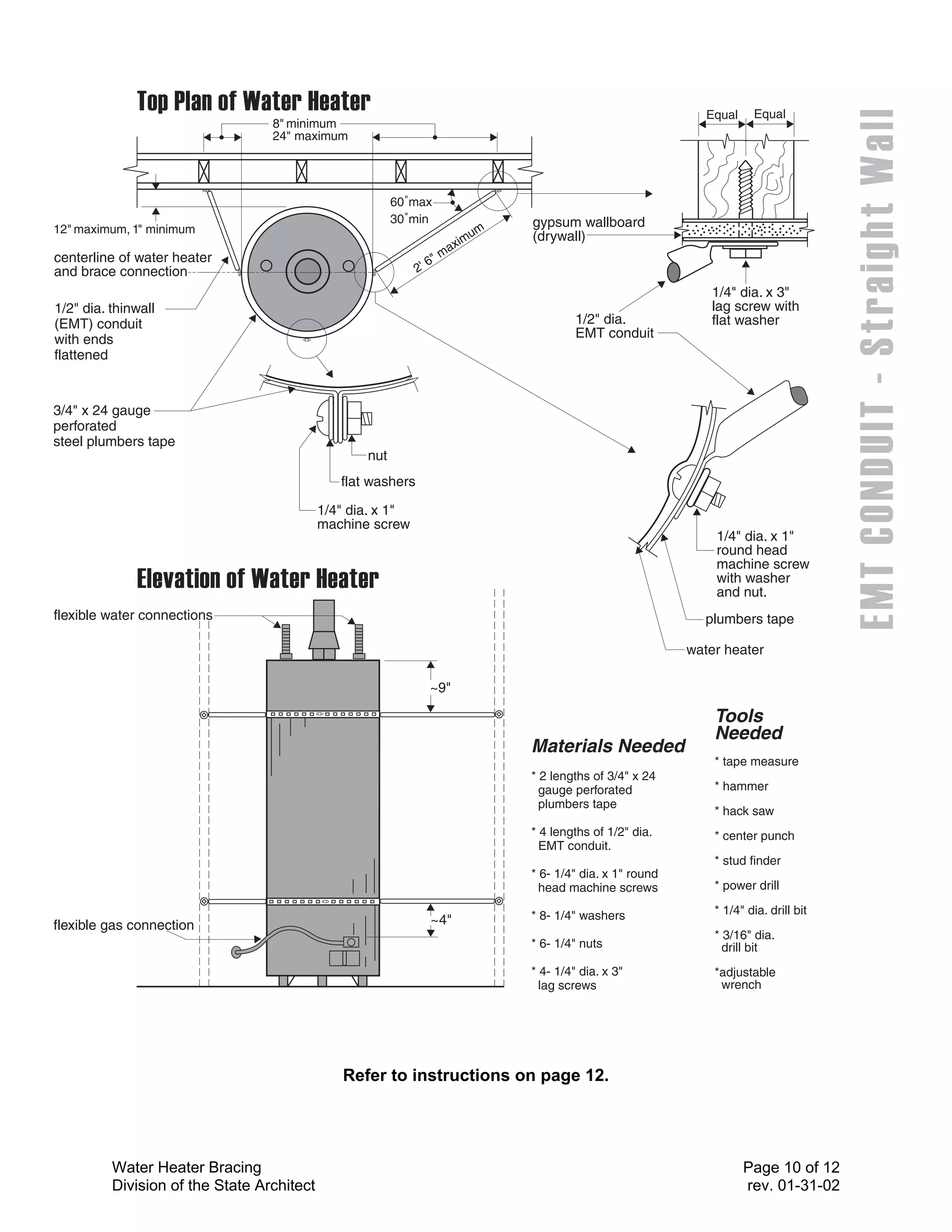
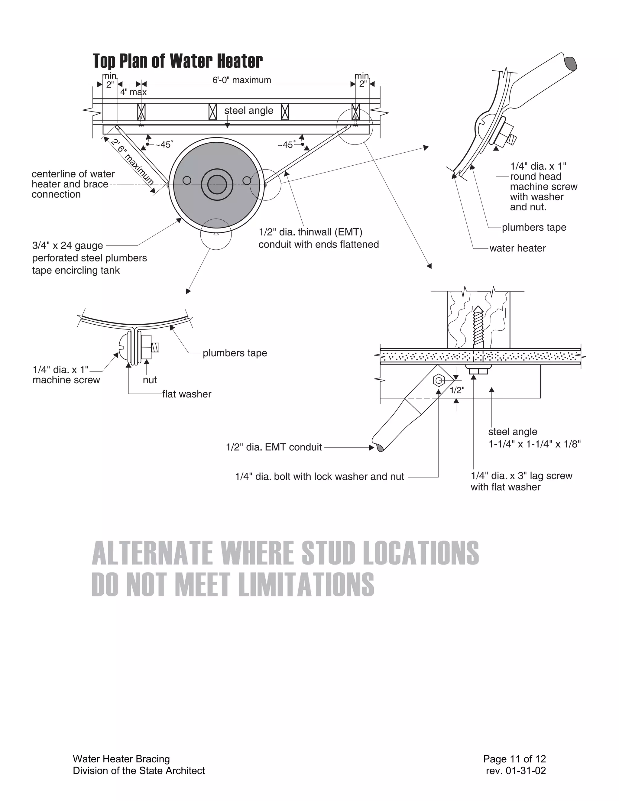
Guidelines for
    Earthquake Bracing
of Residential Water Heaters


 Department of General Services
  Division of the State Architect
      1102 “Q” Street, Suite 5100
        Sacramento, CA 95811
        Phone: (916) 324-7099
           Fax: (916) 327-3371
    Email: terence.fong@dgs.ca.gov


      Revised November 30, 2005
Introduction
During past earthquakes, water heaters have moved or tipped over if they were not securely
anchored to adjacent walls or floors. This movement has resulted in gas line or water line leaks,
and electrical wiring damage. Gas line leaks and damaged electrical wiring pose health and fire
hazards, and water line leaks can cause significant and costly property damage.
California law (Health & Safety Code Sections 19210-19217) requires:
  • Any new or replacement water heater sold in California on or after July 1, 1991 be braced,
    anchored or strapped when installed to resist falling or horizontal displacement due to
    earthquake forces.
  • The seller of any real property containing a water heater to certify in writing to the purchaser
    that water heater bracing requirements have been met.

The Division of the State Architect (DSA) has prepared these guidelines, which illustrate several
earthquake bracing systems for typical (30 to 75 gallon capacity) residential water heater
installations. These guidelines meet the bracing requirements of California’s building and
plumbing codes, which require that a minimum of two sets of bracing straps be provided to
secure the water heater against movement.
These guidelines were developed for water heaters with a capacity of 52 gallons or less, and
may also be utilized for water heaters with a capacity of up to 75 gallons, provided an additional
(third) set of bracing straps is provided at mid-height of the water heater. Earthquake bracing
details for water heaters with a capacity greater than 75 gallons should be approved by the local
building department prior to installation.
Limitations:
These guidelines do not replace any requirements adopted by local building departments. The
installation of residential water heaters (including seismic bracing) is under the jurisdiction of
local building departments.
These guidelines do not address water heater installation in an attic or other unusual location
(such as a water heater not located adjacent to a wall).
These guidelines do not address other plumbing code requirements (such as protection from
damage, venting, clearances from combustible materials, and combustion air). Clearances of
water heaters from adjacent walls must meet minimum requirements specified by the
manufacturer and the local building department.

Note:
DSA strongly recommends that code-compliant flexible connectors be provided between the
water heater and any water, gas, and electrical lines.


Water Heater Bracing                                                                    Page 2 of 12
Division of the State Architect                                                        rev. 11-30-05
Methods for Earthquake Bracing
                        of Water Heaters for Residential Use

These guidelines specify two methods for bracing water heaters. One method utilizes plumbers
tape (perforated metal strapping), while the other method utilizes round thin wall metal conduit
(commonly known as EMT).
Plumber’s Tape Bracing: This method utilizes 3/4” perforated 24 gauge steel strapping
(plumber’s tape) to brace the water heater at an adjacent wall.
 • See illustration on page 4 to brace a water heater located adjacent to a room corner.
 • See illustration on page 6 to brace a water heater located adjacent to a straight wall.
EMT Conduit Bracing: This method utilizes 1/2” diameter EMT conduit, in conjunction with 3/4”
perforated 24 gauge steel plumber’s tape, to brace the water heater to an adjacent wall.
 • See illustration on page 8 to brace a water heater located adjacent to a room corner.
 • See illustration on page 10 to brace a water heater located adjacent to a straight wall.
Helpful Hints:
 • One method for locating studs behind the wall finish is to use a small drill bit to drill a series
   of holes through the drywall until a stud is located. Both sides of the stud should be located
   in order to place the pilot hole for the lag screws at the center of the stud. A stud finder
   (magnetic device that locates drywall screws/nails) can also be purchased from your local
   hardware store to locate studs.
 • Lag screws must be installed into a pre-drilled pilot hole (and must be screwed in, not driven
   in with a hammer). A standard cut washer must be installed with the lag screw as shown.
 • It is possible that a 10 foot length of plumber’s tape will not be long enough for this
   installation. If this proves to be the case, the plumber’s tape can be spliced using a 1/4” hex
   head bolt or 1/4” round head machine screw (RHMS) with washers and a nut.
 • A vise is the simplest method for flattening the ends of the conduit. The conduit can also be
   flattened by placing it on a hard flat surface (i.e. garage floor) and striking it with a hammer.
Insulation Blankets
If the water heater has an Insulation blanket around the outside of the tank, it should be
removed and reinstalled after the bracing system is completed.
Water Heaters on a Raised Platform
The plumbing code requires that a gas water heater located in a garage must have the pilots,
burners or heating elements, and switches located at least 18” above the floor level. Gas water
heaters are generally placed on a platform to meet this code requirement. It is recommended
that the water heater be secured to the platform, and that the platform be secured to the floor
and/or adjacent walls.
Water Heater Bracing Attachment to a Concrete or Concrete Masonry Wall
Mechanical (expansion-type) anchor bolts or chemical (epoxy adhesive) anchor bolts may be
used to secure bracing or strapping to concrete or concrete masonry walls. The mechanical or
chemical anchor bolt should be a minimum 3/8” diameter, with 2” minimum embedment at the
concrete or masonry, and must be installed in accordance with the manufacturer’s instructions.
The concrete or concrete masonry (gray block) must be competent, without significant cracks
(1/16” width or larger). Anchor bolts must not be installed at ungrouted (hollow) cells in concrete
masonry walls.


Water Heater Bracing                                                                   Page 3 of 12
Division of the State Architect                                                       rev. 11-30-05
6" maximum


                                                                                                  flexible water connections
first stud not behind water heater

                      7" minimum                                                                           water heater


                                                                                                   6" maximum

                                                                                           3/4" x 24 gauge perforated steel
                                                                                           plumbers tape encircling tank
 plumbers                                                                                  from front and back.
                       line connecting points of
 tape                  support must pass through
 layout                water heater tank as shown.
 (2 pieces)


                                                                                                                                             Equal
                                                                                              e
                                                                                           tap
                                                                                  e   rs
                                                                               mb
                                                                        p lu


                                                                                                                                             Equal
             flexible water connections                                                           1/4" dia. x 3" lag screw
                                                                                                  with flat washer

                                                                                                                            wood stud
                                                                                ~9"


                                                                                                                                           Tools
                                                                                                                                           Needed
                                                                                                                                           * power drill

                                                                                                     Materials Needed                      * 3/16" Drill bit
                                                                                                                                           * measuring
                                                                                                     * 4 lengths of 3/4" x 24                tape
             flexible gas connection                                            ~4"                    gauge perforated plumbers
                                                                                                       tape.                               * adjustable
                                                                                                                                             wrench
                                                                                                     * 8 - 1/4" x 3" lag screws
                                                                                                       and washers.                        * stud finder
                                           top of supporting platform


                                              Refer to instructions on page 5.

         Water Heater Bracing                                                                                                      Page 4 of 12
         Division of the State Architect                                                                                          rev. 01-31-02
Plumber’s Tape Bracing
                 Water Heater Located Adjacent to Room Corner
                                    See Illustration on Page 4

1. Mark the water heater approximately 9 inches below the top for the upper strap location, and
   4 inches above the top of the controls for the lower strap.
2. Using a stud finder or another appropriate method, locate the nearest wall stud not directly
   behind the water heater (see illustration on page 4).
3. Stretch a string between the two support studs and verify that the distance from the string to
   the face of the water heater is at least seven inches (as shown on the illustration). If it is not
   at least seven inches, it will be necessary to either move the water heater, or utilize the
   alternative support detailing shown on page 11, which utilizes a steel ledger angle (1-1/4” x
   1-1/4” x 1/8”) at the bracing attachments to the wall.
4. Transfer marks on the water heater horizontally onto the adjacent walls where the studs
   identified in step 2 are located.
5. Drill 3/16” diameter x 3” deep pilot holes into the support studs at each lag screw location.
6. Anchor one end of each length of plumber’s tape (4 total) to a support stud with a 1/4”
   diameter x 3” lag screw, wrap the plumber’s tape around the water heater, and pull the tape
   tightly against the support stud on the opposite wall.
7. Secure each length of plumber’s tape (4 total) at the support stud at the opposite wall with a
   lag screw, and cut off any excess length of tape. It is important that the tape be taut. If the
   tape is not taut, remove one or both lag screws and reinstall in the another hole in the
   plumber’s tape, and then reinstall the lag screw(s) into the support stud.


Water Heater Bracing                                                                     Page 5 of 12
Division of the State Architect                                                         rev. 01-31-02
1/4" dia. x 3"
                  wood 2x4       gypsum wallboard                lag screw
                  ledger                            6" minimum                    Materials Needed                   Tools
                                                                                                                     Needed
                                                                                  * gypsum wallboard
 1" minimum


                                                                                    (fire resistant drywall)         * power drill

                                                                                  * 2 lengths of 2x4's               * 1/4" drill bit
                      2"                                                  2"
                     min.                                                min.                                        * 3/16" drill bit
                                                                                  * 4 lengths of 3/4"x 24
                                                                 1/4" dia. x 5"     gauge perforated                 * stud finder
                                                                 lag screw          plumbers tape
                                                                                                                     * measuring
                                                                 water heater     * 4- 1/4" x 5" lag screws            tape

                                                                                  * 4- 1/4" x 3" lag screws          * adjustable
                                                                                                                       wrench
 plumbers                    3/4" x 24 gauge perforated
 tape                        steel plumbers tape
 layout
 (2 pieces)
                                                          centerline of


                                                                                                                                         Equal
                                                          lag screw and 2x4

                                                                                                               gypsum wallboard

                                                                                                                 wood 2x4 ledger
                                                                                                         1/4" x 3" dia. lag
                                                                                                         screw with washer

                                                                                                            3/4" x 24 gauge
                                                                                                            plumbers tape
flexible water
connections
                                                                                                 Equal Equal


                                                          ~9"          1 3/4"
                                                                                                                        wood stud


                                                                                                                gypsum wallboard
                                                                       1 3/4"
                                                                                                                (drywall)

                                                          ~4"                                             1/4" x 5" lag screw

                                                                                                     washer
flexible gas connection
                                                                                            wood 2x4 ledger


                                                  Refer to instructions on page 7.


              Water Heater Bracing                                                                                       Page 6 of 12
              Division of the State Architect                                                                           rev. 01-31-02
Plumber’s Tape Bracing
                  Water Heater Located Adjacent to Straight Wall

                                   See Illustration on Page 6

This method requires that the water heater be at least 2-1/2” from the wall. It may be necessary
to move the water heater to use this method.

1. Mark the water heater approximately 9 inches down from the top and 4 inches up from the
   top of the controls. Transfer these marks to the walls.
2. Locate the studs to receive the wood 2x4 ledgers that are to be centered at the heights
   marked on the wall.
3. Measure the distance between the centerline of the studs that are to support the upper 2x4
   ledger and add 4 inches. Cut both 2x4 ledgers to this length.
4. Drill a 1/4” diameter hole two inches from each end of each 2x4 ledger, located at the center
   of the 3-1/2” width of the 2x4 ledger.
5. Place the upper 2x4 ledger on the wall at the correct height (i.e. lining up the 1/4” hole over
   the center of the wall studs at the previously marked height). Through the 1/4” hole, mark
   the hole location on the stud and then remove the ledger. Drill a 3/16” diameter x 3” depth
   hole in the stud.
6. Place the upper 2x4 ledger on the wall and insert the 1/4” diameter x 5” lag screws through
   the holes in the ledger and the 3/16” holes in the wall stud. Tighten the screw only enough
   to hold the 2x4 in place as the 2x4 will have to be removed to drill holes in the top of the 2x4
   for the plumber’s tape connection (see step 7).
7. Mark the appropriate locations for connection of the plumber’s tape and measure the
   distance from the face of the 2x4 to the face of the water heater. Remove the 2x4 from the
   wall. Drill the 3/16” diameter holes in the top of the 2x4. At the face of the 2x4 ledger,
   adjacent to the water heater, place two or more layers of Type X gypsum wallboard (secure
   with drywall screws or nails). The water heater must be flush at the drywall when the 2x4
   ledger is in place against the wall.
    A 24” length of wood (1x4 or 2x4) may be used to obtain a flush fit between the water heater
    and the 2x4 ledger, provided at least a 1-inch thickness of Type X gypsum wallboard is
    installed adjacent to the water heater.
8. Place the 2x4 ledger behind the water heater and install a 1/4” x 5” lag screw at each end of
   the 2x4 ledger. Measure the distance from the hole at the top of the 2x4 ledger, around the
   circumference of the water heater and back to the same hole, then add 2 inches to that
   measurement. Cut a length of plumber’s tape to this dimension. Place the cut length of
   plumber’s tape tightly around the water heater and attach both ends of the tape to the top of
   the 2x4 with a 1/4” x 3” lag screw. Repeat the process for the other hole at the top of the
   2x4 ledger.
9. Repeat Steps 5 through 8 for the lower 2x4 ledger and plumber’s tape.


Water Heater Bracing                                                                   Page 7 of 12
Division of the State Architect                                                       rev. 01-31-02
water heater
                                                                     6" maximum


7" minimum
                                                                     6" maximum                         plumbers tape
line connecting
points of support
must pass through
water heater tank
as shown.                                                                                               1/4" DIA. x 1"
                                                                                                        round head
3/4" x 24 gauge                                                                                         machine screw
perforated steel                         2'                                                             with washer
                                              6"
plumbers tape                                      m                                                    and nut.
                                                       ax
                                                         im
encircling tank                                            um

                                                                                                          1/2" DIA.EMT


                                                                                                        1/4" DIA. x 3"
                                                                                                        lag screw with
1/4" dia. x 1"                                                                                          flat washer.
machine screw           nut
                              flat washer


                                                                                                                            Equal
       flexible water


                                                                                                                            Equal
       connections
                                                                             plumbers tape

                                                                     ~9"                                    wood stud


                                                                              Materials Needed
                                                                                                                 Tools Needed
                                                                             * 2 lengths of 3/4" x 24
                                                                               gauge perforated                  * tape measure
                                                                               plumbers tape
1/2" diameter                                                                                                    * hammer
thinwall (EMT)
                                                                             * 2 lengths of 1/2" dia.            * hack saw
conduit with ends
                                                                               EMT conduit
flattened
                                                                                                                 * center punch
                                                                             * 10- 1/4" dia. x 1" round
                                                                               head machine screws               * stud finder

                                                                             * 12- 1/4" washers                  * power drill
                                                                     ~4"
                                                                                                                 * 1/4 dia. drill bit
                                                                             * 10- 1/4"nuts
                                                                                                                 * 3/16" dia. drill bit
       flexible gas connection                                               * 4- 1/4" dia. x 3"
                                                                               lag screws                        * adjustable wrench


                                                   Refer to instructions on page 9.


       Water Heater Bracing                                                                                     Page 8 of 12
       Division of the State Architect                                                                         rev. 01-31-02
EMT Conduit Bracing
                 Water Heater Located Adjacent to Room Corner

                                   See Illustration on Page 8

1. Mark the water heater 9 inches down from the top and approximately 4 inches up from the
   top of the controls. Transfer these marks to the walls.
2. Locate the wall studs on both sides of the water heater that meet the minimum and
   maximum criteria shown on the illustration (page 8).
3. Transfer marks on the water heater horizontally to the adjacent wall where the studs located
   in Step 2 are located.
4. Drill a 3/16” diameter x 3” pilot hole at these four stud locations to receive a 1/4” diameter x
   3” lag screw.
5. Measure the circumference of the water heater and add 2 inches to this measurement. Cut
   two pieces of plumbers tape to this length. Place a 1/4” x 1” round head machine screw
   (RHMS) with washer through the end hole of each end of these pieces. Bend the ends of
   the tape out 90 degrees as close to the edge of the washer as possible then remove the
   bolt. The tape can be broken at the smaller holes by holding the tape with pliers and
   bending several times.
6. Place the tape around the water heater and place a 1/4” x 1” RHMS through the bent ends
   of the tape. Install a washer and nut on the bolt and tighten. The tape should be tight
   around the water heater. If the tape is not tight, remove the bolt and place it through the
   next adjacent 1/4” diameter hole after bending the tape out 90 degrees at that point. Install
   a washer and nut on the bolt and tighten. Repeat this procedure for the other tape.
7. Measure the distance of a line formed by connecting a hole in the wall stud to a 1/4” hole on
   the plumber’s tape nearest to where the line would tangent or almost tangent the water
   heater surface and add 1 inch to this dimension. Cut a piece of 1/2” diameter EMT conduit
   to this length. Repeat this procedure for the other locations.
8. Using a hammer or vice, flatten 1 inch at each end of the four pieces of EMT conduit. Be
   sure to flatten the ends of the conduit in the same plane.
9. Drill a 1/4” hole in one end of each conduit approximately 1/2” from the end and then bend
   up the flattened 1” section approximately 45 degrees.
    This angle will have to be corrected slightly as the work progresses. Place the conduit hole
    over the 1/4” drilled hole in the wall stud and mark the other end at one of the holes in the
    plumber’s tape nearest the tangential point on the water heater. Mark this location on the
    tape, conduit and water heater. Remove the conduit and drill a 1/4“ hole at the mark for the
    bolt through the flattened end of the conduit. Repeat this procedure for the other three
    locations.
    Loosen the tape around the water heater and place a 1/4” x 1” RHMS from the inside
    through the tape and hole in the conduit at all four locations. Tighten the tape around the
    water heater so that the bolts are at the marks on the water heater. It may be easier to do
    one side of the water heater at a time as positioning may be difficult. Place the conduit on
    the bolt protruding from the tape and install a washer and nut then tighten. Position the
    opposite end of the conduit at the hole in the wall stud and install a 1/4” x 3” lag screw.
    Repeat this procedure for the other three conduits.


Water Heater Bracing                                                                   Page 9 of 12
Division of the State Architect                                                       rev. 01-31-02
Equal    Equal
                                  8" minimum
                                  24" maximum


                                                         60˚max
                                                         30˚min                    gypsum wallboard
12" maximum, 1" minimum                                                       um
                                                                            im     (drywall)
                                                                        m ax
centerline of water heater                                         6"
and brace connection                                          2'
                                                                                                                  1/4" dia. x 3"
1/2" dia. thinwall                                                                                                lag screw with
(EMT) conduit                                                                               1/2" dia.             flat washer
with ends                                                                                   EMT conduit
flattened


3/4" x 24 gauge
perforated
steel plumbers tape
                                                   nut
                                               flat washers

                                            1/4" dia. x 1"
                                            machine screw
                                                                                                                   1/4" dia. x 1"
                                                                                                                   round head
                                                                                                                   machine screw
                                                                                                                   with washer
                                                                                                                   and nut.
flexible water connections                                                                                       plumbers tape

                                                                                                               water heater

                                                                   ~9"

                                                                                                                   Tools
                                                                                                                   Needed
                                                                                   Materials Needed
                                                                                                                   * tape measure
                                                                                   * 2 lengths of 3/4" x 24
                                                                                     gauge perforated              * hammer
                                                                                     plumbers tape
                                                                                                                   * hack saw
                                                                                   * 4 lengths of 1/2" dia.        * center punch
                                                                                     EMT conduit.
                                                                                                                   * stud finder
                                                                                   * 6- 1/4" dia. x 1" round
                                                                                     head machine screws           * power drill

                                                                                   * 8- 1/4" washers               * 1/4" dia. drill bit
flexible gas connection                                            ~4"
                                                                                                                   * 3/16" dia.
                                                                                   * 6- 1/4" nuts                    drill bit
                                                                                   * 4- 1/4" dia. x 3"             *adjustable
                                                                                     lag screws                     wrench


                                               Refer to instructions on page 12.


          Water Heater Bracing                                                                                            Page 10 of 12
          Division of the State Architect                                                                                 rev. 01-31-02
min.                              6'-0" maximum                  min.
                  2"                                                               2"
                        4" max

                                                     steel angle


                                    ~45˚                           ~45˚
                  2'
                      6"
                        m


                                                                                                                 1/4" dia. x 1"
                           ax
                             im


centerline of water                                                                                              round head
                               um


heater and brace                                                                                                 machine screw
connection                                                                                                       with washer
                                                                                                                 and nut.

                                                             1/2" dia. thinwall (EMT)                          plumbers tape
3/4" x 24 gauge                                              conduit with ends flattened                    water heater
perforated steel plumbers
tape encircling tank


                                              plumbers tape
1/4" dia. x 1"
machine screw                 nut
                                     flat washer                                                 1/2"


                                                                                                            steel angle
                                                     1/2" dia. EMT conduit                                  1-1/4" x 1-1/4" x 1/8"


                                                       1/4" dia. bolt with lock washer and nut          1/4" dia. x 3" lag screw
                                                                                                        with flat washer


         Water Heater Bracing                                                                             Page 11 of 12
         Division of the State Architect                                                                  rev. 01-31-02
EMT Conduit Bracing
                    Water Heater Located Adjacent to Straight Wall
                                     See Illustration on Page 10

If the location of wall studs do not meet the limitations specified on the page 10 illustration, refer
to the alternate support detailing on page 11, which provides a steel ledger angle for attachment
of the braces at the wall.

1. Mark the water heater 9 inches from the top and approximately 4 inches up from the top of
   the controls. Transfer these marks to the wall.
2. Using a stud finder or another appropriate method, locate the closest wood studs in the wall
   on both sides of the water heater, but not directly behind the water heater (see illustration).
3. Transfer the marks on the water heater (See Step 1) horizontally to the center of the wood
   studs located in Step 2.
4. Drill a 3/16” diameter x 3” deep pilot hole (4 total) at the locations noted in Step 3 to receive
   1/4” diameter x 3” lag screws.
5. Measure the water heater circumference and add 2 inches to that measurement. Cut two
   pieces of plumber’s tape to this length. Place a 1/4” x 1” RHMS with washer through the
   end hole of each end of the plumber’s tape and bend the tape out 90 degrees as close to
   the edge of the washer as possible. Remove the bolt and washer. Plumber’s tape typically
   has 1/4” diameter holes 1” apart with 1/8” diameter holes between. The tape can be broken
   at the smaller holes by holding the tape with pliers and bending the tape several times.
6. Place the plumber’s tape around the water heater at the top and bottom marks with the 90
   degree bends meeting in front of the water heater. Install a 1/4” x 1” bolt with washer and
   nut through the holes in the 90 degree bends and tighten the nut. The tape should be tight
   around the water heater. If it is not tight, remove the bolt and place it through the next
   adjacent 1/4” diameter hole after bending the tape to 90 degrees at that point.
7. Measure the distance of a line formed by connecting a hole in the wall stud to a 1/4” hole on
   the plumber’s tape nearest to where the line would tangent or almost tangent the tank
   surface, and 1 inch to this measurement. Cut a piece of 1/2” diameter conduit to this length.
   Repeat this procedure for the other three locations.
8. Using a hammer or vice, flatten 1 inch at each end of the four pieces of conduit. Be sure to
   flatten both ends of the conduit in the same plane.
9. Drill a 1/4” hole in one end of each conduit approximately 1/2” from the end. Measure 1 inch
   in from each end and bend the flattened conduit up approximately 45 degrees. This angle
   will have to be corrected slightly as the work progresses. Place the conduit over the hole in
   the wall stud and mark the other end at one of the holes in the plumbers tape. Be sure to
   mark the hole in the tape to be used and the corresponding point for the hole in the flattened
   conduit as well as the location of the connection on the water tank. Drill a 1/4” hole at the
   mark in the center of the flattened conduit end. Repeat this procedure for the other three
   conduit pieces.
10. Loosen the tape around the water heater and place a 1/4” x 1” RHMS from the inside
   through the holes marked on all the tapes. Tighten the tape around the water heater so that
   the bolts are at the marks on the water heater (See Step 9). It may be easier to do one side
   of the tank at a time, as positioning the tape can be difficult. Place the conduit on the bolt
   protruding from the top and place a washer and nut on the bolt and tighten. A 4d finish nail
   inserted in the slot in the bolt head will prevent the head from turning. Position the opposite
   end of the conduit at the hole in the wall stud and insert a lag screw with washer and tighten.
   Repeat this procedure for the other three conduit braces.


Water Heater Bracing                                                                    Page 12 of 12
Division of the State Architect                                                         rev. 01-31-02

More Related Content

Similar to Water Heater Guidelines State Architect

7 basic valve questions to specify the correct valve
7 basic valve questions to specify the correct valve7 basic valve questions to specify the correct valve
7 basic valve questions to specify the correct valveDesign World
 
Penstocks, powerhouse and tailrace
Penstocks, powerhouse and tailracePenstocks, powerhouse and tailrace
Penstocks, powerhouse and tailraceRakesh Sunari Magar
 
Basic information about workshop
Basic information about workshopBasic information about workshop
Basic information about workshopDr. Ramesh B
 
Installation, testing and jointing of lt and ht power cables up to 33 kv
Installation, testing and jointing of lt and ht power cables up to 33 kvInstallation, testing and jointing of lt and ht power cables up to 33 kv
Installation, testing and jointing of lt and ht power cables up to 33 kvAlexander Decker
 
Types of wires, three phase system earthing
Types of wires, three phase system earthing Types of wires, three phase system earthing
Types of wires, three phase system earthing wasim shaikh
 
Laying, jointing and testing of pipes
Laying, jointing and testing of pipesLaying, jointing and testing of pipes
Laying, jointing and testing of pipessathyan s
 
Presentation: Induced AC Mitigation for Safety and Corrosion Control
Presentation: Induced AC Mitigation for Safety and Corrosion ControlPresentation: Induced AC Mitigation for Safety and Corrosion Control
Presentation: Induced AC Mitigation for Safety and Corrosion ControlMarcellus Drilling News
 
CS Unitec Band Saws Catalog Pages
CS Unitec Band Saws Catalog PagesCS Unitec Band Saws Catalog Pages
CS Unitec Band Saws Catalog PagesCS Unitec
 
10 different equipment used in Distribution Substation
10 different equipment used in Distribution Substation10 different equipment used in Distribution Substation
10 different equipment used in Distribution SubstationDevanshVarma1
 
A Training Report Of Saltlake 132/33kv Substation
A Training Report Of Saltlake 132/33kv SubstationA Training Report Of Saltlake 132/33kv Substation
A Training Report Of Saltlake 132/33kv SubstationSubhrajit Ghosh
 
PPT ON CIM ,BHEL HARIDWAR
PPT ON CIM ,BHEL HARIDWARPPT ON CIM ,BHEL HARIDWAR
PPT ON CIM ,BHEL HARIDWARABHISHEK SINGH
 
pdfcoffee.com_lecture-part-3-pipes-and-fittings-pdf-free.pdf
pdfcoffee.com_lecture-part-3-pipes-and-fittings-pdf-free.pdfpdfcoffee.com_lecture-part-3-pipes-and-fittings-pdf-free.pdf
pdfcoffee.com_lecture-part-3-pipes-and-fittings-pdf-free.pdfStanleyAleruchiWali1
 

Similar to Water Heater Guidelines State Architect (18)

7 basic valve questions to specify the correct valve
7 basic valve questions to specify the correct valve7 basic valve questions to specify the correct valve
7 basic valve questions to specify the correct valve
 
wheel
wheelwheel
wheel
 
White_Paper_Piezo_EN
White_Paper_Piezo_ENWhite_Paper_Piezo_EN
White_Paper_Piezo_EN
 
Penstocks, powerhouse and tailrace
Penstocks, powerhouse and tailracePenstocks, powerhouse and tailrace
Penstocks, powerhouse and tailrace
 
Pullbox sizing
Pullbox sizingPullbox sizing
Pullbox sizing
 
Electrical Wiring
Electrical WiringElectrical Wiring
Electrical Wiring
 
Perfiles
PerfilesPerfiles
Perfiles
 
Basic information about workshop
Basic information about workshopBasic information about workshop
Basic information about workshop
 
2004 0520 Tx
2004 0520 Tx2004 0520 Tx
2004 0520 Tx
 
Installation, testing and jointing of lt and ht power cables up to 33 kv
Installation, testing and jointing of lt and ht power cables up to 33 kvInstallation, testing and jointing of lt and ht power cables up to 33 kv
Installation, testing and jointing of lt and ht power cables up to 33 kv
 
Types of wires, three phase system earthing
Types of wires, three phase system earthing Types of wires, three phase system earthing
Types of wires, three phase system earthing
 
Laying, jointing and testing of pipes
Laying, jointing and testing of pipesLaying, jointing and testing of pipes
Laying, jointing and testing of pipes
 
Presentation: Induced AC Mitigation for Safety and Corrosion Control
Presentation: Induced AC Mitigation for Safety and Corrosion ControlPresentation: Induced AC Mitigation for Safety and Corrosion Control
Presentation: Induced AC Mitigation for Safety and Corrosion Control
 
CS Unitec Band Saws Catalog Pages
CS Unitec Band Saws Catalog PagesCS Unitec Band Saws Catalog Pages
CS Unitec Band Saws Catalog Pages
 
10 different equipment used in Distribution Substation
10 different equipment used in Distribution Substation10 different equipment used in Distribution Substation
10 different equipment used in Distribution Substation
 
A Training Report Of Saltlake 132/33kv Substation
A Training Report Of Saltlake 132/33kv SubstationA Training Report Of Saltlake 132/33kv Substation
A Training Report Of Saltlake 132/33kv Substation
 
PPT ON CIM ,BHEL HARIDWAR
PPT ON CIM ,BHEL HARIDWARPPT ON CIM ,BHEL HARIDWAR
PPT ON CIM ,BHEL HARIDWAR
 
pdfcoffee.com_lecture-part-3-pipes-and-fittings-pdf-free.pdf
pdfcoffee.com_lecture-part-3-pipes-and-fittings-pdf-free.pdfpdfcoffee.com_lecture-part-3-pipes-and-fittings-pdf-free.pdf
pdfcoffee.com_lecture-part-3-pipes-and-fittings-pdf-free.pdf
 

Water Heater Guidelines State Architect

  • 1. Guidelines for Earthquake Bracing of Residential Water Heaters Department of General Services Division of the State Architect 1102 “Q” Street, Suite 5100 Sacramento, CA 95811 Phone: (916) 324-7099 Fax: (916) 327-3371 Email: terence.fong@dgs.ca.gov Revised November 30, 2005
  • 2. Introduction During past earthquakes, water heaters have moved or tipped over if they were not securely anchored to adjacent walls or floors. This movement has resulted in gas line or water line leaks, and electrical wiring damage. Gas line leaks and damaged electrical wiring pose health and fire hazards, and water line leaks can cause significant and costly property damage. California law (Health & Safety Code Sections 19210-19217) requires: • Any new or replacement water heater sold in California on or after July 1, 1991 be braced, anchored or strapped when installed to resist falling or horizontal displacement due to earthquake forces. • The seller of any real property containing a water heater to certify in writing to the purchaser that water heater bracing requirements have been met. The Division of the State Architect (DSA) has prepared these guidelines, which illustrate several earthquake bracing systems for typical (30 to 75 gallon capacity) residential water heater installations. These guidelines meet the bracing requirements of California’s building and plumbing codes, which require that a minimum of two sets of bracing straps be provided to secure the water heater against movement. These guidelines were developed for water heaters with a capacity of 52 gallons or less, and may also be utilized for water heaters with a capacity of up to 75 gallons, provided an additional (third) set of bracing straps is provided at mid-height of the water heater. Earthquake bracing details for water heaters with a capacity greater than 75 gallons should be approved by the local building department prior to installation. Limitations: These guidelines do not replace any requirements adopted by local building departments. The installation of residential water heaters (including seismic bracing) is under the jurisdiction of local building departments. These guidelines do not address water heater installation in an attic or other unusual location (such as a water heater not located adjacent to a wall). These guidelines do not address other plumbing code requirements (such as protection from damage, venting, clearances from combustible materials, and combustion air). Clearances of water heaters from adjacent walls must meet minimum requirements specified by the manufacturer and the local building department. Note: DSA strongly recommends that code-compliant flexible connectors be provided between the water heater and any water, gas, and electrical lines. Water Heater Bracing Page 2 of 12 Division of the State Architect rev. 11-30-05
  • 3. Methods for Earthquake Bracing of Water Heaters for Residential Use These guidelines specify two methods for bracing water heaters. One method utilizes plumbers tape (perforated metal strapping), while the other method utilizes round thin wall metal conduit (commonly known as EMT). Plumber’s Tape Bracing: This method utilizes 3/4” perforated 24 gauge steel strapping (plumber’s tape) to brace the water heater at an adjacent wall. • See illustration on page 4 to brace a water heater located adjacent to a room corner. • See illustration on page 6 to brace a water heater located adjacent to a straight wall. EMT Conduit Bracing: This method utilizes 1/2” diameter EMT conduit, in conjunction with 3/4” perforated 24 gauge steel plumber’s tape, to brace the water heater to an adjacent wall. • See illustration on page 8 to brace a water heater located adjacent to a room corner. • See illustration on page 10 to brace a water heater located adjacent to a straight wall. Helpful Hints: • One method for locating studs behind the wall finish is to use a small drill bit to drill a series of holes through the drywall until a stud is located. Both sides of the stud should be located in order to place the pilot hole for the lag screws at the center of the stud. A stud finder (magnetic device that locates drywall screws/nails) can also be purchased from your local hardware store to locate studs. • Lag screws must be installed into a pre-drilled pilot hole (and must be screwed in, not driven in with a hammer). A standard cut washer must be installed with the lag screw as shown. • It is possible that a 10 foot length of plumber’s tape will not be long enough for this installation. If this proves to be the case, the plumber’s tape can be spliced using a 1/4” hex head bolt or 1/4” round head machine screw (RHMS) with washers and a nut. • A vise is the simplest method for flattening the ends of the conduit. The conduit can also be flattened by placing it on a hard flat surface (i.e. garage floor) and striking it with a hammer. Insulation Blankets If the water heater has an Insulation blanket around the outside of the tank, it should be removed and reinstalled after the bracing system is completed. Water Heaters on a Raised Platform The plumbing code requires that a gas water heater located in a garage must have the pilots, burners or heating elements, and switches located at least 18” above the floor level. Gas water heaters are generally placed on a platform to meet this code requirement. It is recommended that the water heater be secured to the platform, and that the platform be secured to the floor and/or adjacent walls. Water Heater Bracing Attachment to a Concrete or Concrete Masonry Wall Mechanical (expansion-type) anchor bolts or chemical (epoxy adhesive) anchor bolts may be used to secure bracing or strapping to concrete or concrete masonry walls. The mechanical or chemical anchor bolt should be a minimum 3/8” diameter, with 2” minimum embedment at the concrete or masonry, and must be installed in accordance with the manufacturer’s instructions. The concrete or concrete masonry (gray block) must be competent, without significant cracks (1/16” width or larger). Anchor bolts must not be installed at ungrouted (hollow) cells in concrete masonry walls. Water Heater Bracing Page 3 of 12 Division of the State Architect rev. 11-30-05
  • 4. 6" maximum flexible water connections first stud not behind water heater 7" minimum water heater 6" maximum 3/4" x 24 gauge perforated steel plumbers tape encircling tank plumbers from front and back. line connecting points of tape support must pass through layout water heater tank as shown. (2 pieces) Equal e tap e rs mb p lu Equal flexible water connections 1/4" dia. x 3" lag screw with flat washer wood stud ~9" Tools Needed * power drill Materials Needed * 3/16" Drill bit * measuring * 4 lengths of 3/4" x 24 tape flexible gas connection ~4" gauge perforated plumbers tape. * adjustable wrench * 8 - 1/4" x 3" lag screws and washers. * stud finder top of supporting platform Refer to instructions on page 5. Water Heater Bracing Page 4 of 12 Division of the State Architect rev. 01-31-02
  • 5. Plumber’s Tape Bracing Water Heater Located Adjacent to Room Corner See Illustration on Page 4 1. Mark the water heater approximately 9 inches below the top for the upper strap location, and 4 inches above the top of the controls for the lower strap. 2. Using a stud finder or another appropriate method, locate the nearest wall stud not directly behind the water heater (see illustration on page 4). 3. Stretch a string between the two support studs and verify that the distance from the string to the face of the water heater is at least seven inches (as shown on the illustration). If it is not at least seven inches, it will be necessary to either move the water heater, or utilize the alternative support detailing shown on page 11, which utilizes a steel ledger angle (1-1/4” x 1-1/4” x 1/8”) at the bracing attachments to the wall. 4. Transfer marks on the water heater horizontally onto the adjacent walls where the studs identified in step 2 are located. 5. Drill 3/16” diameter x 3” deep pilot holes into the support studs at each lag screw location. 6. Anchor one end of each length of plumber’s tape (4 total) to a support stud with a 1/4” diameter x 3” lag screw, wrap the plumber’s tape around the water heater, and pull the tape tightly against the support stud on the opposite wall. 7. Secure each length of plumber’s tape (4 total) at the support stud at the opposite wall with a lag screw, and cut off any excess length of tape. It is important that the tape be taut. If the tape is not taut, remove one or both lag screws and reinstall in the another hole in the plumber’s tape, and then reinstall the lag screw(s) into the support stud. Water Heater Bracing Page 5 of 12 Division of the State Architect rev. 01-31-02
  • 6. 1/4" dia. x 3" wood 2x4 gypsum wallboard lag screw ledger 6" minimum Materials Needed Tools Needed * gypsum wallboard 1" minimum (fire resistant drywall) * power drill * 2 lengths of 2x4's * 1/4" drill bit 2" 2" min. min. * 3/16" drill bit * 4 lengths of 3/4"x 24 1/4" dia. x 5" gauge perforated * stud finder lag screw plumbers tape * measuring water heater * 4- 1/4" x 5" lag screws tape * 4- 1/4" x 3" lag screws * adjustable wrench plumbers 3/4" x 24 gauge perforated tape steel plumbers tape layout (2 pieces) centerline of Equal lag screw and 2x4 gypsum wallboard wood 2x4 ledger 1/4" x 3" dia. lag screw with washer 3/4" x 24 gauge plumbers tape flexible water connections Equal Equal ~9" 1 3/4" wood stud gypsum wallboard 1 3/4" (drywall) ~4" 1/4" x 5" lag screw washer flexible gas connection wood 2x4 ledger Refer to instructions on page 7. Water Heater Bracing Page 6 of 12 Division of the State Architect rev. 01-31-02
  • 7. Plumber’s Tape Bracing Water Heater Located Adjacent to Straight Wall See Illustration on Page 6 This method requires that the water heater be at least 2-1/2” from the wall. It may be necessary to move the water heater to use this method. 1. Mark the water heater approximately 9 inches down from the top and 4 inches up from the top of the controls. Transfer these marks to the walls. 2. Locate the studs to receive the wood 2x4 ledgers that are to be centered at the heights marked on the wall. 3. Measure the distance between the centerline of the studs that are to support the upper 2x4 ledger and add 4 inches. Cut both 2x4 ledgers to this length. 4. Drill a 1/4” diameter hole two inches from each end of each 2x4 ledger, located at the center of the 3-1/2” width of the 2x4 ledger. 5. Place the upper 2x4 ledger on the wall at the correct height (i.e. lining up the 1/4” hole over the center of the wall studs at the previously marked height). Through the 1/4” hole, mark the hole location on the stud and then remove the ledger. Drill a 3/16” diameter x 3” depth hole in the stud. 6. Place the upper 2x4 ledger on the wall and insert the 1/4” diameter x 5” lag screws through the holes in the ledger and the 3/16” holes in the wall stud. Tighten the screw only enough to hold the 2x4 in place as the 2x4 will have to be removed to drill holes in the top of the 2x4 for the plumber’s tape connection (see step 7). 7. Mark the appropriate locations for connection of the plumber’s tape and measure the distance from the face of the 2x4 to the face of the water heater. Remove the 2x4 from the wall. Drill the 3/16” diameter holes in the top of the 2x4. At the face of the 2x4 ledger, adjacent to the water heater, place two or more layers of Type X gypsum wallboard (secure with drywall screws or nails). The water heater must be flush at the drywall when the 2x4 ledger is in place against the wall. A 24” length of wood (1x4 or 2x4) may be used to obtain a flush fit between the water heater and the 2x4 ledger, provided at least a 1-inch thickness of Type X gypsum wallboard is installed adjacent to the water heater. 8. Place the 2x4 ledger behind the water heater and install a 1/4” x 5” lag screw at each end of the 2x4 ledger. Measure the distance from the hole at the top of the 2x4 ledger, around the circumference of the water heater and back to the same hole, then add 2 inches to that measurement. Cut a length of plumber’s tape to this dimension. Place the cut length of plumber’s tape tightly around the water heater and attach both ends of the tape to the top of the 2x4 with a 1/4” x 3” lag screw. Repeat the process for the other hole at the top of the 2x4 ledger. 9. Repeat Steps 5 through 8 for the lower 2x4 ledger and plumber’s tape. Water Heater Bracing Page 7 of 12 Division of the State Architect rev. 01-31-02
  • 8. water heater 6" maximum 7" minimum 6" maximum plumbers tape line connecting points of support must pass through water heater tank as shown. 1/4" DIA. x 1" round head 3/4" x 24 gauge machine screw perforated steel 2' with washer 6" plumbers tape m and nut. ax im encircling tank um 1/2" DIA.EMT 1/4" DIA. x 3" lag screw with 1/4" dia. x 1" flat washer. machine screw nut flat washer Equal flexible water Equal connections plumbers tape ~9" wood stud Materials Needed Tools Needed * 2 lengths of 3/4" x 24 gauge perforated * tape measure plumbers tape 1/2" diameter * hammer thinwall (EMT) * 2 lengths of 1/2" dia. * hack saw conduit with ends EMT conduit flattened * center punch * 10- 1/4" dia. x 1" round head machine screws * stud finder * 12- 1/4" washers * power drill ~4" * 1/4 dia. drill bit * 10- 1/4"nuts * 3/16" dia. drill bit flexible gas connection * 4- 1/4" dia. x 3" lag screws * adjustable wrench Refer to instructions on page 9. Water Heater Bracing Page 8 of 12 Division of the State Architect rev. 01-31-02
  • 9. EMT Conduit Bracing Water Heater Located Adjacent to Room Corner See Illustration on Page 8 1. Mark the water heater 9 inches down from the top and approximately 4 inches up from the top of the controls. Transfer these marks to the walls. 2. Locate the wall studs on both sides of the water heater that meet the minimum and maximum criteria shown on the illustration (page 8). 3. Transfer marks on the water heater horizontally to the adjacent wall where the studs located in Step 2 are located. 4. Drill a 3/16” diameter x 3” pilot hole at these four stud locations to receive a 1/4” diameter x 3” lag screw. 5. Measure the circumference of the water heater and add 2 inches to this measurement. Cut two pieces of plumbers tape to this length. Place a 1/4” x 1” round head machine screw (RHMS) with washer through the end hole of each end of these pieces. Bend the ends of the tape out 90 degrees as close to the edge of the washer as possible then remove the bolt. The tape can be broken at the smaller holes by holding the tape with pliers and bending several times. 6. Place the tape around the water heater and place a 1/4” x 1” RHMS through the bent ends of the tape. Install a washer and nut on the bolt and tighten. The tape should be tight around the water heater. If the tape is not tight, remove the bolt and place it through the next adjacent 1/4” diameter hole after bending the tape out 90 degrees at that point. Install a washer and nut on the bolt and tighten. Repeat this procedure for the other tape. 7. Measure the distance of a line formed by connecting a hole in the wall stud to a 1/4” hole on the plumber’s tape nearest to where the line would tangent or almost tangent the water heater surface and add 1 inch to this dimension. Cut a piece of 1/2” diameter EMT conduit to this length. Repeat this procedure for the other locations. 8. Using a hammer or vice, flatten 1 inch at each end of the four pieces of EMT conduit. Be sure to flatten the ends of the conduit in the same plane. 9. Drill a 1/4” hole in one end of each conduit approximately 1/2” from the end and then bend up the flattened 1” section approximately 45 degrees. This angle will have to be corrected slightly as the work progresses. Place the conduit hole over the 1/4” drilled hole in the wall stud and mark the other end at one of the holes in the plumber’s tape nearest the tangential point on the water heater. Mark this location on the tape, conduit and water heater. Remove the conduit and drill a 1/4“ hole at the mark for the bolt through the flattened end of the conduit. Repeat this procedure for the other three locations. Loosen the tape around the water heater and place a 1/4” x 1” RHMS from the inside through the tape and hole in the conduit at all four locations. Tighten the tape around the water heater so that the bolts are at the marks on the water heater. It may be easier to do one side of the water heater at a time as positioning may be difficult. Place the conduit on the bolt protruding from the tape and install a washer and nut then tighten. Position the opposite end of the conduit at the hole in the wall stud and install a 1/4” x 3” lag screw. Repeat this procedure for the other three conduits. Water Heater Bracing Page 9 of 12 Division of the State Architect rev. 01-31-02
  • 10. Equal Equal 8" minimum 24" maximum 60˚max 30˚min gypsum wallboard 12" maximum, 1" minimum um im (drywall) m ax centerline of water heater 6" and brace connection 2' 1/4" dia. x 3" 1/2" dia. thinwall lag screw with (EMT) conduit 1/2" dia. flat washer with ends EMT conduit flattened 3/4" x 24 gauge perforated steel plumbers tape nut flat washers 1/4" dia. x 1" machine screw 1/4" dia. x 1" round head machine screw with washer and nut. flexible water connections plumbers tape water heater ~9" Tools Needed Materials Needed * tape measure * 2 lengths of 3/4" x 24 gauge perforated * hammer plumbers tape * hack saw * 4 lengths of 1/2" dia. * center punch EMT conduit. * stud finder * 6- 1/4" dia. x 1" round head machine screws * power drill * 8- 1/4" washers * 1/4" dia. drill bit flexible gas connection ~4" * 3/16" dia. * 6- 1/4" nuts drill bit * 4- 1/4" dia. x 3" *adjustable lag screws wrench Refer to instructions on page 12. Water Heater Bracing Page 10 of 12 Division of the State Architect rev. 01-31-02
  • 11. min. 6'-0" maximum min. 2" 2" 4" max steel angle ~45˚ ~45˚ 2' 6" m 1/4" dia. x 1" ax im centerline of water round head um heater and brace machine screw connection with washer and nut. 1/2" dia. thinwall (EMT) plumbers tape 3/4" x 24 gauge conduit with ends flattened water heater perforated steel plumbers tape encircling tank plumbers tape 1/4" dia. x 1" machine screw nut flat washer 1/2" steel angle 1/2" dia. EMT conduit 1-1/4" x 1-1/4" x 1/8" 1/4" dia. bolt with lock washer and nut 1/4" dia. x 3" lag screw with flat washer Water Heater Bracing Page 11 of 12 Division of the State Architect rev. 01-31-02
  • 12. EMT Conduit Bracing Water Heater Located Adjacent to Straight Wall See Illustration on Page 10 If the location of wall studs do not meet the limitations specified on the page 10 illustration, refer to the alternate support detailing on page 11, which provides a steel ledger angle for attachment of the braces at the wall. 1. Mark the water heater 9 inches from the top and approximately 4 inches up from the top of the controls. Transfer these marks to the wall. 2. Using a stud finder or another appropriate method, locate the closest wood studs in the wall on both sides of the water heater, but not directly behind the water heater (see illustration). 3. Transfer the marks on the water heater (See Step 1) horizontally to the center of the wood studs located in Step 2. 4. Drill a 3/16” diameter x 3” deep pilot hole (4 total) at the locations noted in Step 3 to receive 1/4” diameter x 3” lag screws. 5. Measure the water heater circumference and add 2 inches to that measurement. Cut two pieces of plumber’s tape to this length. Place a 1/4” x 1” RHMS with washer through the end hole of each end of the plumber’s tape and bend the tape out 90 degrees as close to the edge of the washer as possible. Remove the bolt and washer. Plumber’s tape typically has 1/4” diameter holes 1” apart with 1/8” diameter holes between. The tape can be broken at the smaller holes by holding the tape with pliers and bending the tape several times. 6. Place the plumber’s tape around the water heater at the top and bottom marks with the 90 degree bends meeting in front of the water heater. Install a 1/4” x 1” bolt with washer and nut through the holes in the 90 degree bends and tighten the nut. The tape should be tight around the water heater. If it is not tight, remove the bolt and place it through the next adjacent 1/4” diameter hole after bending the tape to 90 degrees at that point. 7. Measure the distance of a line formed by connecting a hole in the wall stud to a 1/4” hole on the plumber’s tape nearest to where the line would tangent or almost tangent the tank surface, and 1 inch to this measurement. Cut a piece of 1/2” diameter conduit to this length. Repeat this procedure for the other three locations. 8. Using a hammer or vice, flatten 1 inch at each end of the four pieces of conduit. Be sure to flatten both ends of the conduit in the same plane. 9. Drill a 1/4” hole in one end of each conduit approximately 1/2” from the end. Measure 1 inch in from each end and bend the flattened conduit up approximately 45 degrees. This angle will have to be corrected slightly as the work progresses. Place the conduit over the hole in the wall stud and mark the other end at one of the holes in the plumbers tape. Be sure to mark the hole in the tape to be used and the corresponding point for the hole in the flattened conduit as well as the location of the connection on the water tank. Drill a 1/4” hole at the mark in the center of the flattened conduit end. Repeat this procedure for the other three conduit pieces. 10. Loosen the tape around the water heater and place a 1/4” x 1” RHMS from the inside through the holes marked on all the tapes. Tighten the tape around the water heater so that the bolts are at the marks on the water heater (See Step 9). It may be easier to do one side of the tank at a time, as positioning the tape can be difficult. Place the conduit on the bolt protruding from the top and place a washer and nut on the bolt and tighten. A 4d finish nail inserted in the slot in the bolt head will prevent the head from turning. Position the opposite end of the conduit at the hole in the wall stud and insert a lag screw with washer and tighten. Repeat this procedure for the other three conduit braces. Water Heater Bracing Page 12 of 12 Division of the State Architect rev. 01-31-02