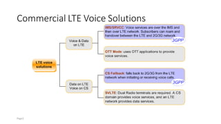
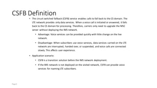
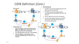
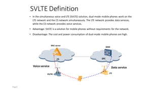
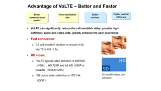
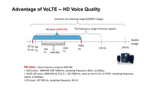
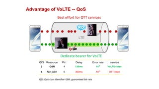
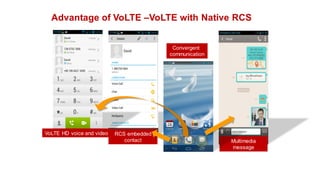
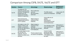
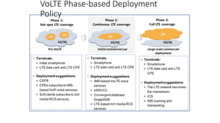
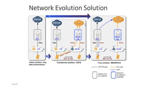
VOLTE Introduction
Commercial LTE Voice Solutions
Page2
CSFB Definition
• The circuit switched fallback (CSFB) service enables calls to fall back to the CS domain. The
LTE network provides only data services. When a voice call is initiated or answered, it falls
back to the CS domain for processing. Therefore, carriers only need to upgrade the MSC
server without deploying the IMS network.
• Advantage: Voice services can be provided quickly with little change on the live
network.
• Disadvantage: When subscribers use voice services, data services carried on the LTE
network are interrupted, handed over, or suspended, and voice calls are connected
slowly. This affects user experience.
• Application scenario:
• CSFB is a transition solution before the IMS network deployment.
• If the IMS network is not deployed on the visited network, CSFB can provide voice
services for roaming LTE subscribers.
Page3
CSFB Definition (Cont.)
• Originating side
• The UE sends a voice call request to the
MME. The MME then instructs the UE to
fall back to the 2G or 3G network.
• The UE falls back to the 2G or 3G network.
• The UE initiates a call based on the
normal originating flow on the 2G or 3G
network.
MME
SGs
LTE
MSC server
CS EPC
2G/3G
MME
LTE
MSC server
CS EPC
2G/3G
Fallback
3
SGs
1
4 2
⚫ Terminating side
 The MSC server sends a paging requestto the
MME over the SGs interface.
 The MME forwardsthepaging request
instructing the UE to fall back to the 2G or 3G
network.
 The UE falls back to the 2G or 3G network.
 The UE sends a paging responseto the MSC
server and answers thecall based on the
normalterminating flow.
1
2
Fallback
3
Page4
SVLTE Definition
• In the simultaneous voice and LTE (SVLTE) solution, dual-mode mobile phones work on the
LTE network and the CS network simultaneously. The LTE network provides data services,
while the CS network provides voice services.
• Advantage: SVLTE is a solution for mobile phones without requirements for the network.
• Disadvantage: The cost and power consumption of dual-mode mobile phones are high.
LTE
2G/3G
CS EPC
MSC server
MME
Data service
Voice service
Page5
OTT Definition
• Over-the-top (OTT) is a solution that uses APPs, such as the Skype, to provide voice
services for LTE subscribers.
• Advantage:
• Only the OTT server needs to be deployed to the live network and slight change is
required. The OTT can enhance user experience by offering rich multimedia services.
• Disadvantages:
• The OTT solution is not carrier-class-based and has low reliability.
• The OTT solution cannot provide E2E QoS guarantee.
• The OTT solution is hard to provide common services, such as emergency calls and
interception, and services that are used only by regulatory bodies.
• Roaming and interconnection are hard to be implemented due to lack of standards.
Page6
VoLTE Definition
Voice over long term evolution (VoLTE) is an IMS-based voice solution defined
by 3GPP. By deploying the IMS network, operators not only migrate traditional
voice and short message services on live networks but also integrate voice
services with various enhanced functions to diversify services.
VoLTE advantages
⚫ The VoLTE solution inherits all services provided by the CS network, including common services, such as
emergency calls and interception, and services that areused only by regulatory bodies.
⚫ The VoLTE solution can implement E2E QoS controland guaranteevoice call quality.
⚫ In the VoLTE solution, voiceservices are carried on IP networks. Therefore, subscriberscan enjoy richer
multimedia services through the IMS network, competewith OTT.
⚫ Subscriber identities (such as the MSISDN) arereserved, which maximizes carriers'resourceusageand
facilitates service profitgain.
⚫ The IMS architecture, supported by mature 3GPP standards and specifications, is considered to be the
next generation corenetwork by the communications industry. TheIMS architectureensures roaming
services and network interworking.
Page7
Three Forces to Drive
VoLTE Development
•HD voice
•HD video session
•Faster call connection
•Rich multimedia communication
experience (IM/Presence
service/enhancedaddressbook)
• The LTE network features high
bandwidth, low delay, all IP, and always
online, which facilitates OTT
application development.
• IMS-based multimedia voice services
and RCS serve as carriers' main
competitive sources.
• VoLTE provided by carriers outperforms
OTT in the following aspects:
• Telecommunication subscriber ID
and authentication
• Interconnection and interworking
• QoS guarantee
• Handover and roaming to 2G and 3G
networks
• Fee package bound to mobile
broadband
• Fault troubleshooting and customer
care
•The spectral efficiency of LTE voice
services increases over four times
compared with that of CS voice
services.
•Number of voice channels per sector
•Source: Qualcomm
The time for settingupaVoLTE call is
half thatfor settingupa 3G call.
1. Competing with OTT
(real driving force) 33.33%
3. Unifyingthe network and reducingTCO
(long-termdrivingforce) 26.42%
2. User experience
(permanent driving force) 30.19%
VoLTE/RCS driving force
investigation result
(159 participants in the IMS summit
in April 2011)
Faster connectionrate
Better communication
quality
Higher spectral
efficiency
.
Richer
services
Page8
Advantage of VoLTE – Better and Faster
SD and HD video size
compare
Faster connection
rate
Better
communication
quality
Higher spectral
efficiency
Richer
services
⚫ Fast connection:
 CS call establish duration is around 4-5s,
VoLTE is 0.8 -1.5s.
⚫ HD video:
 VoLTE typical video definition is 480*640
(VGA), HD 720P and full HD 1080P is
possible(H.264/H.265)
 3G typical video definition is 176*144
(QCIF)
⚫ VoLTE can significantly reduce the call establish delay, provide high-
definition audio and video calls, greatly enhance the user experience
Advantage of VoLTE -- HD Voice Quality
20
Hz
20k Hz
Common ear listening range (CD/MP3 range)
HD voice: (Twice frequency rangethe AMR-NB)
• VoCS voice: AMR-NB 300~3400 Hz, sampling frequency 8kHz, 12.2Kbps。
• VoLTE HD voice: AMR-WB (G.722.2 ) : 50~7000 Hz, same as the G.711 in PSTN, sampling frequency
16kHz, 23.85Kbps.
• CD music: 20~20K Hz, sampling frequency 44.1K.
50
Hz
80
Hz
12k Hz
The frequency range of human speech
7000
Hz
HD voice (AMR-WB)
300
Hz
3400
Hz
CS
(AMR-NB)
Audio
range
Advantage of VoLTE -- QoS
Dedicate bearer for VoLTE
Best effort for OTT services
QCI Resource Pri. Delay Error rate service
2 GBR 4 150ms 10-6
VoLTEvideo
6 Non-GBR 6 300ms 10-3
OTT video
LTE
QCI: QoS class identifier GBR: guaranteed bit rate
Advantage of VoLTE –VoLTE with Native RCS
VoLTE HD voice and video RCS embedded
contact Multimedia
message
Convergent
communication
Comparison Among CSFB, SVLTE, VoLTE and OTT
Solution Feature Advantage Disadvantage
Deployment
Suggestion
VoLTE
The IMS and LTE
networks provide voice
services.The handover
betweenthe LTE
network and 2G/3G
network is supported.
Rich multimedia
services.
HD voice/video.
E2E QoS
The IMS network
needs to be deployed.
Large-scale LTE
coverage
OTT
Voice services are
implemented byAPPs
of OTT carriers.
Slight change is
required on live
networks.
Voice calls are not
reliable.
Roaming and
interworking are hard
to be implemented.
-
CSFB
UEs attach to the LTE
network. When a UE
initiates or receives a
call, the UE falls back to
the CS network.
Slight change is
required on live
networks.
New NEs do not need
to be deployed.
The call delay is long.
User experience is
affected.
Initial phase of
the LTE network
(transition
solution)
SVLTE
Terminals attach to both
the CS and LTE
networks. The CS
network provides voice
services.
The live network does
not need to be adjusted.
Costs of mobile
phones are high.
Advantages of the
LTE network cannot
be used.
Initial phase of
the LTE network
(transition
solution)
Page13
Key Technologies Involved in VoLTE
• Voice based on IMS
• VoLTE voice services are IMS-based.
• SRVCC/eSRVCC
• If VoLTE voice services need to be handed over the GSM or RAN network, SRVCC or
eSRVCC is used.
• ICS for VoLTE
• To ensure that subscribers have consistent user experiences on the LTE and CS
networks, ICS is used.
Page14
IMS-based Voice Services
E-UTRAN
I/S-CSCF
SBC
/P-CSCF
Handset
EPC
MME
S-GW/P-
GW
IMS Core
PCRF
Default bearer: IMS signaling streams
Dedicated bearer: Voice media streams
Voice media streams
SIP signaling streams
• A default beareris set up for IMS signaling streams when the UE attaches to the network.
• Afterthe UE initiates a call, SIP signaling streams for call connectionis transmitted over the
default bearer through the P-GW to the IMS Core.
• A dedicatedbearerfor IMS voice media streams is set up during call connection.
• Voice media streams of the calling and called parties are transmitted over the dedicated bearer.
• The PCRF assigns and delivers QoS rules for signaling and mediastreams during the setup of
default and dedicated bearers.This ensures quality of signaling and media streams.
Page15
VoLTE Basic
Call
• A dedicated
bearer for IMS
voice media
streams is set up
during call
connection
Page16
SRVCC Definition
• Single radio voice call continuity(SRVCC) is an IMS-based VoLTE.
• VCC describes how a voice call can be continuedwhen a UE moves between the target CS domain and the
LTE domain supporting VoIP services.
• SRVCC describes how a voice call can be continuedwhen a Single Radio UE moves between LTE/Pre-LTE and
2G/3G networks, that is, when a Single Radio UE switches an call session between IMS/LTE and CS.
Page17
SRVCC Definition (Cont.)
• Calls are set up in the LTE over VoIP / VoIMS.
• When a subscriber moves to an area uncovered by the LTE network while holding a call,
the call is switched to the CS domain. SRVCC interprets a switchover process.
Page18
⚫ SRVCC solution: The media
handover point is a peer
device. Such as a peer UE.
⚫ E2E signaling and bearer are
re-established.
⚫ The IMS network sends the
updated media information to
the remote network, and a
session is interrupted around
1s.
eSRVCC Definition
• Target: The handover delay is less than 300 ms
• Policy: The remote session update process is optimized. The media handover point is
near to the local side.
⚫ Method: Media and signaling
planes are anchored at the
ATCF or ATGW to avoid the
IMS session transfer process.
When an eSRVCC handover is
performed, only the bearer
between the UE and the
ATGW needs to be set up.
⚫ The original bearer is reused to
transmit media streams
between the peer device and
the ATGW.
Page19
eSRVCC Vs SRVCC
First eSRVCC testing (Vienna 201210)
before
after
SRVCC
E2E media re-establish
LTE
RAN
G/U
RAN
IMS/SBC
> 1.5s
Remote
side
eSRVCC
Local media establish
LTE
RAN
G/U
RAN
IMS/SBC
(ATCF & ATGW)
~ 0s
Remote
side
< 230ms
LTE to GSM HO time ~ 230ms (Beijing 201404)
ICS Definition
• IMS centralized services (ICS) describe how services of subscribers who access the CS domain or IP-CAN
using different terminalsare managed on the IMS network in centralized mode.
• With the ICS feature, all services are centralized to IMS. Therefore, subscribers can have consistent user
experiences on the LTE and CS networks.
• By deployingan MSC server that supports the ICS feature on a network, ICS subscribers can use services
providedby IMS during the initialphase of LTE in the following scenarios:
• CS subscribers who have subscribed to the ICS feature wish to use IMS services without changing their numbers.
• VoLTE subscribers who roam to or experience an SRVCC handover to a CS network wish to continue to use the IMS
services.
Page21
ICS Definition (Cont.)
• The ICS solution becomes the
best choice for evolution from the
mobile softswitch to IMS. The
eMSC server functions as a SIP UA
and connects subscribers to the
IMS Core.
• MSC server enhancements for ICS,
the MSC server that supports the
ICS feature, is called mobile
access gateway control function
(mAGCF). In this document, the
MSC server enhancements for ICS
is called eMSC server.
IMS Core
MGW
AS
mAGCF
LTE
2G/3G
LTE subscriber
MSC server
AS AS
Service layer
Centralized service
trigger point
Access layer
ICS Architecture
xPONand
FBB
CS subscriber
Page22
VoLTE Phase-based Deployment
Policy
LTE
LTE
2G/3G
LTE
2G/3G
LTE
2G/3G
Phase 2:
Continuous LTE coverage
Phase 1:
Hot spot LTE coverage
Phase 3:
Full LTE coverage
Pre-VoLTE Initial commercial use Large-scalecommercial
deployment
⚫ Terminals:
 Initial smartphone
 LTE data card and LTE CPE
⚫ Deploymentsuggestions:
 CSFB
 CPEs subscribe to IMS-
based VoIP voice services.
 Softclients subscribe to rich
media RCS services.
⚫ Terminals:
 Smartphone
 LTE data card and LTE CPE
⚫ Deploymentsuggestions:
 IMS-based VoLTE voice
services
 eSRVCC
 Convergentdatabase
SingleSDB
 LTE-based rich media RCS
services
⚫ Terminals:
 Smartphone
 LTE data card and LTE
CPE
⚫ Deploymentsuggestions:
 The LTE network becomes
the mainstream.
 ICS
 IMS roaming and
interworking
Network Evolution Solution
Page24
Evolution to IMS/SRVCC/ICS
The live network
solution evolves to ICS
in the following ways:
• Evolution from
deployment of the
overlay eMSC server
to ICS
• Direct Evolution to
ICS
Live network MSC servers
MSC servers
Deploy the SRVCC IWF/MGCF.
Enhanced with the mAGCF/SRVCC IWF
Page25
Evolution from CSFB to ICS
The live network solution evolves from CSFB to ICS in the following ways:
• Evolution from the standard CSFB to ICS
• Evolution from the CSFB proxy to ICS
MSC servers
MSC servers
MSC servers MSC servers
VoLTE (overlay eMSC server)
Enhanced with CSFB
Deploy MSC servers to serve as CSFB proxies. Enhanced with the SRVCC IWF/MGCF
VoLTE Network Architecture
Operation Support Layer and Service Layer
Operationsupport layer
⚫ Operation support layer
 Functions: This layer provides various functions,
such as network management, subscription data
storage, unified operations on the web portal,
charging, and equipment management.
 NEs: DMS, SPG, CCF, and EMS
Service layer
⚫ Service layer
 Functions: This layer consists of different
application servers and resourceservers to provide
services, such as instant messaging, conferences,
games, as well as service capabilities, such as group
and media resourcecapabilities.
 NEs: ATS and RCS
ATS
(MMtelAS/SCC AS/IP-SM-
GW/IM-SSF/AnchorAS)
Page28
Core Layer
Core layer
⚫ The core layer is divided into the followingthree
parts:
 IMS domain: NEs in the IMS domain implement
such functions for LTE subscribersas registration,
authentication, session path control, servicetrigger,
routeselection, resourcecontrol, inter-domain
interworking, and access resourcecontrol.
 CS domain: NEs in the CS domain implement such
functions for LTE subscribersas mobility
management and voice services, including
handovers and CSFB.
 SingleSDB: The SingleSDB provides the functions of
the USCDB, HLR, IMS-HSS, SAE-HSS, PCRF,
DNS/ENUMfor centralized storageof VoLTE
subscribers'servicedata. The data can be used by
the CS, IMS, and EPC domains.
Page29
Access Layer
Access layer
⚫ Access layer
 Functions:
 The access layer controls LTEsubscriber access
and provides mobility management for LTE
subscribers.
 When an LTE subscriber is in the LTE coverage, the
subscriber can access an IMS network through the
EPC.
 When a subscriber moves outof the LTE coverage,
the subscriber can access an IMS network through
a 2G/3G network using ICS.
 If the 2G/3G network does not supportICS, a
subscriber accesses a legacy CS network.
 NEs: eMSC server (mAGCF), S-GW, P-GW, and MME
Page30
Terminal Layer
Terminal layer
⚫ Terminal layer
 LTE terminals are classified into VoLTE terminals
and non-VoLTE terminals.
 VoLTE terminals are those that rely on an IMS or
LTE network to usevoice services. They include
Single Radio terminals, LTE data cards, and
CPEs.
 Non-VoLTEterminals are thosethat rely on a CS
network to usevoice services and that connect
to an LTE network to usedata services. They
include Dual Radio and CSFB terminals.
 Types: Single Radio terminals (SRVCCterminals),
LTE data cards, CPEs, DualRadio terminals (SVLTE
terminals), and CSFBterminals
Page31
NEs at the Operation Support Layer
NE Name Function
SPG
Provides a unified service provisioning interface and the web portal
and sends the service provisioning commands received from the
BSS to the HSS, ENUM, and AS.
CCF
Collects ACR messages from IMS charging NEs, such as the CSCF,
ATS, and MGCF, processes the ARC messages to generate CDRs,
and sends the CDRs to a BC specified by carriers.
EMS Interworks with the BSS to manage NEs in a centralized manner.
Page32
NEs at the Service Layer
NE Name Function
Common
telephony
application
server
(ATS)
⚫ MMTel AS: provides basic and supplementary multimedia
telephony services.
⚫ SCC AS: interworks with the SRVCC IWF and ATCF/ATGW to
provide the eSRVCC function, and provides the T-ADS function
to select a domain for the called party.
⚫ IP-SM-GW: provides short message interworking between IMS
and CS domains.
⚫ IM-SSF: triggers IN services in the CS domain based on the
subscription information provided by the S-CSCF and the local
configuration on the IM-SSF.
• Anchor AS: Routes VoLTE subscribers' calls to the IMS
domain to trigger convergent services by IN-based number
redirection of the anchor AS, when the VoLTE subscribers
originate or receive a call in the CS domain.
RCS AS
Provides the Open Mobile Alliance Instant Message (OMA IM),
Presence, XML document management server (XDMS), and data
synchronization (DS) functions to implement the IM, Presence, and
Network Address Book services.
Page33
NEs at the Service Layer - ATS
• The ATS provides traditional
mobile services and
multimedia services.
Business
service
Mobile
special
service
TISPAN
PSTN
service
3GPP
MMTel
service
IMS network
Mobile terminal Soft
phone
SIP
terminal
CPE
MBB FBB PSTN
POTS POTS
ATS
(MMTel + SCC AS + IP-SM-GW+ IM-
SSF + anchor AS)
⚫ The ATS integrates the functions of the MMTel AS, IM-SSF, SCC AS, Anchor AS, and IP-SM-
GW to reduce the number of attempts to trigger iFC during calls and realize service
resources sharing.
Page34
NEs at the Service Layer - SCC AS (ATS)
⚫ The service centralizationand continuityapplication server
(SCC AS) implementshandoversin the IMS domainand
updatesthe media information about the remote UE. In
details, the SCC AS does the following:
EPC
CS
IMS Core
ISC
eMSC server
(SRVCC IWF)
LTE
GERAN
UMTS
Calledparty
access
SCC AS
Calling
connection 1
Calling
connection2
Calledconnection3
Mediaconnection1
Mediaconnection2
Handover
Call signaling anchorpoint
SCC AS
▪ Analyzes information
required by a handover.
▪ Associates handover
requests and anchors
sessions.
▪ Implements handovers
between the LTE network
and the UMTS network.
Page35
NEs at the Service Layer - T-ADS (SCC AS)
• T-ADS
• As defined in 3GPP specifications, domain selection by the network is implemented by the terminating access
domain selection (T-ADS).
• The T-ADS function is integrated with the SCC AS. The SCC AS queries the convergent HLR/HSS for the UE type and
access domain information and implements domain selection based on the carrier policies. Based on the T-ADS
information, the SCC AS determines whether the current call is routed to the IMS or CS network.
Page36
NEs at the Service Layer - IP-SM-GW (ATS)
⚫ The IP short message gateway (IP-SM-GW)
provides short message interworking between
IMS and CS domains.
IMS Core
ISC
IP-SM-GW
UE
OCS CGF/CDF
HSS
•SMS-GMSC/
•SMS-IWMSC
SMSC
SME
Ro Rf
Sh
E/Gd
1 SIP message
2 Translates instantmessages to shortmessages.
3 Sends short
messages to UEs.
⚫ After the UE sends a SIP message, the IP-SM-GW converts the instant message (SIP
message) to a text message. When the UE registers with IMS, the IP-SM-GW downloads
the SMSC address to a local directory.
Page37
NEs at the Service Layer - Anchor AS
(ATS)
The anchor AS anchors calls from the CS
network to the IMS network as follows:
⚫ Routes VoLTE subscribers' calls to the
IMS domain to trigger convergent
services by IN-based number redirection
of the anchor AS, when the VoLTE
subscribers originate or receive a call in
the CS domain.
⚫ Routes VoLTE subscribers' calls to the
IMS domain by IN-based number
redirection of the anchor AS, when the
VoLTE subscribers receive calls from CS
subscribers.
CS MSC server
IMS
Anchor AS
CS MSC server
IMS
Anchor AS
VoLTE subscriber
LTE
VoLTE
subscriber
AS
Page38
NEs at the Service Layer - RCS AS
• The RCS AS provides the OMA IM, Presence, XDMS, and DS functions to
implement the IM, Presence, and Network Address Book services.
RCS
Capability discovery
RCS-e
IM (1-1 and 1-M)
File transfer
Image/Video share + Voice
Offline storage and forwarding
Presence
NAB/CAB
VoLTE integration
Page39
NEs at the Core Layer
NE Name Function
IMS-HSS
(FE)
Controls subscriberroaming and stores the following information about a subscriber
in the IMS network: subscriberIDs,authentication data, service data, access
parameters,service trigger information, and roaming information.
SAE-
HSS/HLR
(FE)
Stores service-related data of subscribers,manages subscriptioninformation and
location information, and combines the following NEs:
• HSS in the EPC network
• HLR in CS and PS domains in the core network of the mobile telecommunication
system
USCDB
(BE)
Stores subscriberdata and implements the functions of adding, deleting, updating,
and querying data at the requestof the FE.
DNS/ENUM Implements functions provided by the DNS and the ENUM server.
eMSC
server
(SRVCC
IWF/CSFB
proxy)
Combines the following NEs:
• SRVCC IWF:provides eSRVCC to ensure call continuity when terminals move
from an LTE network to a 2G/3G network.
• CSFB proxy: moves LTE subscribers to a CS domain to provide voice services for
them.
MGCF
Realizes interworking between an IMS network and a PSTN or PLMN network.
If fixed network optimization is required or the live network provides a lot of fixed
network services,the UGC3200 is used as the MGCF. In other scenarios,the
MSOFTX3000is used as the MGCF.
Page40
NEs at the Core Layer (Cont.)
NE Name Function
MRFP
Provides resourcesforannouncement playing and digit collection,voice conferences,
SD video conferences.
I-CSCF/S-
CSCF/BGCF
/MRFC
Combines the following NEs to provide call control, service triggering, and routing
functions:
• I-CSCF:As the entrance to the IMS home network, the I-CSCF assigns or queries
the HSS to selectan appropriate S-CSCF to serve subscribers.
• S-CSCF:The S-CSCF is located on the home network as the central IMS node. It
implements subscription,authentication, session,routes, and service triggering.
• BGCF:The BGCF is located on the home network to selectan MGCF for calls
betweenan IMS network and a PSTN or PLMN network. It is integrated into the S-
CSCF to reduce the need for standalone BGCFs.Therefore,call connectiondelay
is shorten and the reliability is enhanced.
• MRFC: The MRFC controls the MRFP to play announcements and collectdigits,
and provide resources forvoice conferencesand SD video conferences.
Page41
NEs at the Core Layer (Cont.)
NE Name Function
P-
CSCF/SBC/ATC
F/ATGW
• P-CSCF:located on the visited network as the first contact point for
subscriberswithin an IMS domain. The P-CSCF forwards SIP signaling
betweenSIP subscribers and their home networks.
• SBC: provides the core bordergateway function (C-BGF) and interconnection
bordergateway function (I-BGF).The C-BGF is deployedat the edge of an
access network to provide attack protectionand NAT traversal. The I-BGF
provides mediachannels for an IMS network to interwork with other networks
that use SIP or H.323 signaling.
• ATCF/ATGW:located betweenthe P-CSCF and I-CSCF/S-CSCF and
interworks with the SCC AS to provide eSRVCC.
MGW/IM-MGW
Provides audio media channels for interworking between an IMS network and a
PSTN or PLMN network.
Page42
NEs at the Core Layer - SRVCC IWF
⚫ The SRVCC IWF is collocated
with an MSC server or deployed
as a standalone entity. If the
SRVCC IWF is deployed as a
standalone entity, it functions
as a proxy of the MSC server
and performs conversion for
signaling messages between
the MSC server, SBC, and MME.
EPC
CS
IMS Core
Sv
eMSC server
(SRVCC IWF)
SCC AS
MME
MSC
UE
SRVCC IWF
Handover request
MSC
MSC
MSC
1
Selects target MSC
2
⚫ The SRVCC IWF ensures call continuity when terminals move
from an LTE network to a 2G/3G network. When receiving the
location update request from a UE, the SRVCC IWF changes the
UE access location from the MME to the MSC server based on
the target cell ID contained in the location update request.
Page43
NEs at the Core Layer - ATCF/ATGW
⚫ The ATCF/ATGW is locatedbetween the P-CSCF and I-CSCF/S-CSCF and
interworks with the SCC AS to provide eSRVCC.
• During a call, the ATCF or ATGW determines whether to anchor a call on the media
plane based on carriers' policies and terminal capabilities.
• During an eSRVCC handover, the ATCF or ATGW correlates a handover request
initiated by the SRVCC IWF with the anchored session, updates session bearer
information, and initiates a handover request to the SCC AS.
Signaling before a
handover
Bearer before a
handover
Signaling aftera
handover
Bearer after a
handover
Local handover duration: < 300 ms
PS
CS
SBC
IMS Core
Handover
SCC AS
SRVCC
IWF
2G/3G
LTE
Remote UE
ATCF
ATGW
Change is not required.
Page44
NEs at the Access Layer
NE Name Function
eMSC server
(mAGCF)
Helps ICS subscribers in a CS domain to register with an IMS domain
and provides basic and supplementary services for them.
S-GW/P-GW
• S-GW in an EPC domain: serves as an anchor point for the user
plane between access networks in 3GPP. The S-GW is used as an
interface to screen different access networks in 3GPP.
• P-GW in an EPC domain: serves as an anchor point between a
3GPP access network and non-3GPP access network. It provides
an interface for interworking between a 3GPP access network and
external PDN.
MME
Implements mobility management for LTE subscribers, including
subscriber context and mobility status management, and temporary
identity distribution.
Page45
Interfaces in the IMS and CS domains and
Interworking
Page46
Interfaces for Accessing
Page47
Interfaces and Protocols on the VoLTE
Network
Protocol Purpose
SIP SIP is used to control calls between IMS or CS NEs.
Diameter
Diameter is used to exchange the subscriptionand authentication information
betweenthe CSCF, the MME, and HSS. It is also used to exchange charging
information between the CCF/OCS and IMS NEs.
H.248
H.248 is used to exchange messagesbetweenthe media gateway controller
(such as the MSC server, MGCF, and MRFC) and the media gateway (such as
MGW, IM-MGW, and MRFP).
MAP
MAP defines a means of information exchange among NEs to realize the
roaming function and SMS of UEs.
CAP
CAP is used between the SSP/IM-SSF and SCP to allow CS or IMS subscribers
to use traditional IN services.
ISUP
ISUP is used forsignaling interworking betweenMSC servers,and between the
MSC server/anchorAS and the MGCF.
GTP-C
GTP-C is used to exchange messages betweenthe MME, SRVCC-IWF,and S-
GW.
SGsAP
SGsAP is used to perform mobilitymanagement and paging processesof short
message servicesbetweenan EPC domain and a CS domain.
HTTP HTTP is used to exchange messagesbetweenterminals and DMSs.
Page48
Interfaces and Protocols on the VoLTE
Network - SIP
Interface Location and Function Protocol
Mw
Located betweenthe P-CSCF,I-CSCF,and S-CSCF,the Mw interface
is used for message exchangebetweenCSCFs during IMS registration
and sessionprocessesand also functions as a proxy.
Located betweenthe ATCF and S-CSCF/SRVCC-IWF,the Mw interface
is used to control eSRVCC.
SIP
Mr
The Mr interface is located between the CSCF and the MRFC. By using
the Mr interface,the S-CSCF obtains network resource-relatedservices
from the MRFC, including announcement playing, digit collection,
conferencebridges,and video streams.
SIP
Mi
The Mi interface is located between the S-CSCF and the BGCF.When
the S-CSCF discoversthat a sessionneeds to be routed to the CS
domain, it uses the Mi interface to forward the sessionto the BGCF so
that the BGCF can selectan appropriate breakout to the CS domain.
SIP
Mj
The Mj interface is located between the BGCF and the MGCF. When
the BGCF receives sessioncontrol signaling over the Mi interface,it
selects an appropriate breakout to the CS domain. If the selected
breakout is in the same network as the BGCF,the BGCF uses the Mj
interface to forward the sessioncontrol signaling to the MGCF.
SIP
Page49
Interfaces and Protocols on the VoLTE
Network - SIP (Cont.)
Interface Location and Function
Protoco
l
Mg
The Mg interface is located between the I-CSCF and the MGCF. The
MGCF uses the Mg interface to forward sessioncontrolsignaling from
the CS domain to the I-CSCF so that the CS domain can interwork with
the IMS domain.
SIP
Mk
The Mk interface is located between BGCFs.This interface is used to
forward sessioncontrolsignaling from the BGCF that resides in the
same network as the originating S-CSCF to the BGCF that resides in
the same network as the MGCF.
SIP
Mm
The Mm interface is located betweenthe CSCF and other IP networks.
This interface supports IPv4 and IPv6 addresses.
SIP
ISC
The ISC interface is located betweenthe S-CSCF and the AS. Based
on the iFC template data obtained from the HSS and SIP service
requests sent from an IMS UE, the S-CSCF determineswhether to
trigger a service. If the service needs to be triggered,the S-CSCF
routes the sessionrequestover the ISC interface to a specific AS for
final processing.
SIP
Page50
Interfaces and Protocols on the VoLTE
Network - SIP (Cont.)
Interface Location and Function Protocol
Nc
The Nc interface is located between the MSC server/anchorAS and
the MGCF and between MSC servers.The main functions of this
interface are as follows:
•Manages mobility and handover and provides interworking for CS
subscribers.
•Allows CS subscribers to be anchored in an IMS network.
ISUP/SIP
I2
The I2 interface is located between the mAGCF and the ATCF/I-
CSCF/S-CSCF.This interface is used between a CS network and an
IMS network to allow CS subscribersto access an IMS network. This
interface is also used to convert messages sentfrom the A/Iu-CS
interface to IMS SIP signaling messages.
SIP
Gm
The Gm interface is located betweenan IMS UE and the P-CSCF for
registration and sessioncontrol forIMS subscribers.
SIP
Page51
Interfaces and Protocols on the VoLTE
Network - Diameter
Interfac
e
Location and Function Protocol
Cx
The Cx interface is located between the CSCF and the IMS-HSS. The
CSCF and the IMS-HSS use the Cx interface to perform the following
operations:
• The I-CSCF queries the IMS-HSS forinformation required for selecting
an S-CSCF.
• The CSCF queries the IMS-HSS for routing information.
• The CSCF queries the IMS-HSS for roaming authorization information.
• The CSCF downloads from the IMS-HSS security parameters required
for IMS subscriberauthentication.
• The IMS-HSS sends iFC data associated with the IMS sessionto the
CSCF.
Diameter
Dx
The Dx interface is located between the CSCF and the SLF. If multiple
HSSs are deployed onan IMS network, the CSCF uses the Dx interface
to query the SLF forthe HSS that stores subscriptiondata of a subscriber.
The Dx interface is not required when only one HSS is deployed.
Diameter
Sh
The Sh interface is located between the IMS-HSS and the SIP AS.The
SIP AS uses the Sh interface to query the IMS-HSS for value-added
service data and to synchronize data to the IMS-HSS.
Diameter
Page52
Interfaces and Protocols on the VoLTE
Network - Diameter (Cont.)
Interface Location and Function Protocol
Dh
The Dh interface is located between the SLF and the SIP AS.The AS
uses the Dh interface to identify the HSS that stores subscriberdata
based on the subscriberidentity and home domain information.
Diameter
Rf
The Rf interface is located between the CCF and other entities such as
the CSCF,MRFC, BGCF,and AS.This interface is used for session-
related offline charging.
Diameter
Ro
The Ro interface is located between the OCS and other entities such as
the AS, MRFC, and OCG.This interface is used for session-related
online charging.
Diameter
Rx
The Rx interface is located between the PCRF and the application entity
such as the P-CSCF.The Rx interface is used forsessioninformation
exchange at the application layer. Based on the sessioninformation, the
PCRF determines the policies and charging control schemes to be used.
The PCRF exchanges the decided policies and charging control
schemes with the PCEF.
Diameter
Page53
Interfaces and Protocols on the VoLTE
Network - Diameter (Cont.)
Interface Location and Function Protocol
Gx
The Gx interface is located between the PCRF and the PCEF (such as
the P-GW).The PCRF uses the Gx interface to deliver charging policies
to the PCEF,and the PCEF uses the Gx interface to reportbearer events
to the PCRF.
Diameter
S6a
The S6a interface is located betweenthe MME and the SAE-HSS.This
interface is used to transmit subscriptionand authentication data for
authorized subscribersto access the EPC network.
Diameter
Page54
Interfaces and Protocols on the VoLTE
Network - H.248
Interface Location and Function Protocol
Mp
The Mp interface is located between the MRFC and the MRFP. The
MRFC uses the interface to control the MRFP for announcement
playing, conferences,and DTMF digit collection.
H.248
Mn
The Mn interface is located between the MGCF and the IM-MGW. The
MGCF uses the Mn interface to control mediastreams transmitted on
the IM-MGW and allocation of specialresources.
H.248
Mc
The Mc interface is located between the MSC serverand the MGW.The
MSC serveruses the Mc interface to control media streams transmitted
on the MGW and allocation of specialresources.
H.248
Page55
Interfaces and Protocols on the VoLTE
Network - MAP
Interface Location and Function Protocol
E/Gd
The E/Gd interface is located between the IP-SM-GW and the SMSC for
SMS interworking between an IMS network and a CS domain.
MAP
E
The E interface is located between the MSC server and the SMSC for
SMS interworking.
MAP
Si
The Si interface is located between the IM-SSF and the HLR and is used
to obtain IN service information about subscribers.
MAP
J
The J interface is located betweenthe IP-SM-GW and the HLR and is
used to obtain the routing information about short messages.
MAP
C/D
The C/D interface is located betweenthe MSC server/MGCF/SMSC and
the HLR. The MSC server/SMSC and the HLR use the C/D interface to
perform the following operations:
• The MSC server and SMSC query the HLR for routing information.
• The MSC server sends a location update requestto the HLR.
• The MSC server and the MGCF query the HLR for the roaming
numbers and subscriptioninformationabout subscribers.
• In the convergentHLR/HSS anchoring solution, the HLR uses this
interface to obtain the IMRN from the MGCF.
MAP
Page56
Interfaces and Protocols on the VoLTE
Network - GTP-C
Interface Location and Function Protocol
S11
The S11 interface is located between the MME and the S-GW.The MME
and S-GW use the S11 interface to transmit bearer setup,update, and
deletionmessages.Whena UE is in the ECM-IDLE state, the S-GW
instructs the MME to page the UE to restore the S1 bearer.
GTP-C
Sv
The Sv interface is located between the MME and the SRVCC IWFto
control the eSRVCC handover.
GTP-C
Page57
Interfaces and Protocols on the VoLTE
Network - CAP/HTTP/SGsAP
Interface Location and Function Protocol
CAP
The CAP interface is located betweenthe MSC server/IM-SSF/anchor
AS and the SCP.The CAP interface allows CS or IMS subscribers to use
traditional IN services and CS subscribers to be anchored in an IMS
network.
CAP
HTTP
The HTTP interface is located betweena UE and the DMS. The terminal
uses the HTTP interface to perform self-help upgrade and fault
diagnosis.
HTTP
SOAP
The SOAP interface is located between the SPG and the AS/HSS.The
SPG uses the SOAP interface to deliver commands that are run on the
SPG2800 web portal to the AS or HSS.
HTTP
SGs
The SGs interface is located betweenthe MME and the CSFB MSC
server/CSFB proxy.The SGs interface is used to perform mobility
management and paging procedures betweenan EPC domain and a CS
domain in the CSFB scenario.
SGsAP
Page58

VOLTE_introductions_15673156666666665.pdf

  • 1.
  • 2.
    Commercial LTE VoiceSolutions Page2
  • 3.
    CSFB Definition • Thecircuit switched fallback (CSFB) service enables calls to fall back to the CS domain. The LTE network provides only data services. When a voice call is initiated or answered, it falls back to the CS domain for processing. Therefore, carriers only need to upgrade the MSC server without deploying the IMS network. • Advantage: Voice services can be provided quickly with little change on the live network. • Disadvantage: When subscribers use voice services, data services carried on the LTE network are interrupted, handed over, or suspended, and voice calls are connected slowly. This affects user experience. • Application scenario: • CSFB is a transition solution before the IMS network deployment. • If the IMS network is not deployed on the visited network, CSFB can provide voice services for roaming LTE subscribers. Page3
  • 4.
    CSFB Definition (Cont.) •Originating side • The UE sends a voice call request to the MME. The MME then instructs the UE to fall back to the 2G or 3G network. • The UE falls back to the 2G or 3G network. • The UE initiates a call based on the normal originating flow on the 2G or 3G network. MME SGs LTE MSC server CS EPC 2G/3G MME LTE MSC server CS EPC 2G/3G Fallback 3 SGs 1 4 2 ⚫ Terminating side  The MSC server sends a paging requestto the MME over the SGs interface.  The MME forwardsthepaging request instructing the UE to fall back to the 2G or 3G network.  The UE falls back to the 2G or 3G network.  The UE sends a paging responseto the MSC server and answers thecall based on the normalterminating flow. 1 2 Fallback 3 Page4
  • 5.
    SVLTE Definition • Inthe simultaneous voice and LTE (SVLTE) solution, dual-mode mobile phones work on the LTE network and the CS network simultaneously. The LTE network provides data services, while the CS network provides voice services. • Advantage: SVLTE is a solution for mobile phones without requirements for the network. • Disadvantage: The cost and power consumption of dual-mode mobile phones are high. LTE 2G/3G CS EPC MSC server MME Data service Voice service Page5
  • 6.
    OTT Definition • Over-the-top(OTT) is a solution that uses APPs, such as the Skype, to provide voice services for LTE subscribers. • Advantage: • Only the OTT server needs to be deployed to the live network and slight change is required. The OTT can enhance user experience by offering rich multimedia services. • Disadvantages: • The OTT solution is not carrier-class-based and has low reliability. • The OTT solution cannot provide E2E QoS guarantee. • The OTT solution is hard to provide common services, such as emergency calls and interception, and services that are used only by regulatory bodies. • Roaming and interconnection are hard to be implemented due to lack of standards. Page6
  • 7.
    VoLTE Definition Voice overlong term evolution (VoLTE) is an IMS-based voice solution defined by 3GPP. By deploying the IMS network, operators not only migrate traditional voice and short message services on live networks but also integrate voice services with various enhanced functions to diversify services. VoLTE advantages ⚫ The VoLTE solution inherits all services provided by the CS network, including common services, such as emergency calls and interception, and services that areused only by regulatory bodies. ⚫ The VoLTE solution can implement E2E QoS controland guaranteevoice call quality. ⚫ In the VoLTE solution, voiceservices are carried on IP networks. Therefore, subscriberscan enjoy richer multimedia services through the IMS network, competewith OTT. ⚫ Subscriber identities (such as the MSISDN) arereserved, which maximizes carriers'resourceusageand facilitates service profitgain. ⚫ The IMS architecture, supported by mature 3GPP standards and specifications, is considered to be the next generation corenetwork by the communications industry. TheIMS architectureensures roaming services and network interworking. Page7
  • 8.
    Three Forces toDrive VoLTE Development •HD voice •HD video session •Faster call connection •Rich multimedia communication experience (IM/Presence service/enhancedaddressbook) • The LTE network features high bandwidth, low delay, all IP, and always online, which facilitates OTT application development. • IMS-based multimedia voice services and RCS serve as carriers' main competitive sources. • VoLTE provided by carriers outperforms OTT in the following aspects: • Telecommunication subscriber ID and authentication • Interconnection and interworking • QoS guarantee • Handover and roaming to 2G and 3G networks • Fee package bound to mobile broadband • Fault troubleshooting and customer care •The spectral efficiency of LTE voice services increases over four times compared with that of CS voice services. •Number of voice channels per sector •Source: Qualcomm The time for settingupaVoLTE call is half thatfor settingupa 3G call. 1. Competing with OTT (real driving force) 33.33% 3. Unifyingthe network and reducingTCO (long-termdrivingforce) 26.42% 2. User experience (permanent driving force) 30.19% VoLTE/RCS driving force investigation result (159 participants in the IMS summit in April 2011) Faster connectionrate Better communication quality Higher spectral efficiency . Richer services Page8
  • 9.
    Advantage of VoLTE– Better and Faster SD and HD video size compare Faster connection rate Better communication quality Higher spectral efficiency Richer services ⚫ Fast connection:  CS call establish duration is around 4-5s, VoLTE is 0.8 -1.5s. ⚫ HD video:  VoLTE typical video definition is 480*640 (VGA), HD 720P and full HD 1080P is possible(H.264/H.265)  3G typical video definition is 176*144 (QCIF) ⚫ VoLTE can significantly reduce the call establish delay, provide high- definition audio and video calls, greatly enhance the user experience
  • 10.
    Advantage of VoLTE-- HD Voice Quality 20 Hz 20k Hz Common ear listening range (CD/MP3 range) HD voice: (Twice frequency rangethe AMR-NB) • VoCS voice: AMR-NB 300~3400 Hz, sampling frequency 8kHz, 12.2Kbps。 • VoLTE HD voice: AMR-WB (G.722.2 ) : 50~7000 Hz, same as the G.711 in PSTN, sampling frequency 16kHz, 23.85Kbps. • CD music: 20~20K Hz, sampling frequency 44.1K. 50 Hz 80 Hz 12k Hz The frequency range of human speech 7000 Hz HD voice (AMR-WB) 300 Hz 3400 Hz CS (AMR-NB) Audio range
  • 11.
    Advantage of VoLTE-- QoS Dedicate bearer for VoLTE Best effort for OTT services QCI Resource Pri. Delay Error rate service 2 GBR 4 150ms 10-6 VoLTEvideo 6 Non-GBR 6 300ms 10-3 OTT video LTE QCI: QoS class identifier GBR: guaranteed bit rate
  • 12.
    Advantage of VoLTE–VoLTE with Native RCS VoLTE HD voice and video RCS embedded contact Multimedia message Convergent communication
  • 13.
    Comparison Among CSFB,SVLTE, VoLTE and OTT Solution Feature Advantage Disadvantage Deployment Suggestion VoLTE The IMS and LTE networks provide voice services.The handover betweenthe LTE network and 2G/3G network is supported. Rich multimedia services. HD voice/video. E2E QoS The IMS network needs to be deployed. Large-scale LTE coverage OTT Voice services are implemented byAPPs of OTT carriers. Slight change is required on live networks. Voice calls are not reliable. Roaming and interworking are hard to be implemented. - CSFB UEs attach to the LTE network. When a UE initiates or receives a call, the UE falls back to the CS network. Slight change is required on live networks. New NEs do not need to be deployed. The call delay is long. User experience is affected. Initial phase of the LTE network (transition solution) SVLTE Terminals attach to both the CS and LTE networks. The CS network provides voice services. The live network does not need to be adjusted. Costs of mobile phones are high. Advantages of the LTE network cannot be used. Initial phase of the LTE network (transition solution) Page13
  • 14.
    Key Technologies Involvedin VoLTE • Voice based on IMS • VoLTE voice services are IMS-based. • SRVCC/eSRVCC • If VoLTE voice services need to be handed over the GSM or RAN network, SRVCC or eSRVCC is used. • ICS for VoLTE • To ensure that subscribers have consistent user experiences on the LTE and CS networks, ICS is used. Page14
  • 15.
    IMS-based Voice Services E-UTRAN I/S-CSCF SBC /P-CSCF Handset EPC MME S-GW/P- GW IMSCore PCRF Default bearer: IMS signaling streams Dedicated bearer: Voice media streams Voice media streams SIP signaling streams • A default beareris set up for IMS signaling streams when the UE attaches to the network. • Afterthe UE initiates a call, SIP signaling streams for call connectionis transmitted over the default bearer through the P-GW to the IMS Core. • A dedicatedbearerfor IMS voice media streams is set up during call connection. • Voice media streams of the calling and called parties are transmitted over the dedicated bearer. • The PCRF assigns and delivers QoS rules for signaling and mediastreams during the setup of default and dedicated bearers.This ensures quality of signaling and media streams. Page15
  • 16.
    VoLTE Basic Call • Adedicated bearer for IMS voice media streams is set up during call connection Page16
  • 17.
    SRVCC Definition • Singleradio voice call continuity(SRVCC) is an IMS-based VoLTE. • VCC describes how a voice call can be continuedwhen a UE moves between the target CS domain and the LTE domain supporting VoIP services. • SRVCC describes how a voice call can be continuedwhen a Single Radio UE moves between LTE/Pre-LTE and 2G/3G networks, that is, when a Single Radio UE switches an call session between IMS/LTE and CS. Page17
  • 18.
    SRVCC Definition (Cont.) •Calls are set up in the LTE over VoIP / VoIMS. • When a subscriber moves to an area uncovered by the LTE network while holding a call, the call is switched to the CS domain. SRVCC interprets a switchover process. Page18 ⚫ SRVCC solution: The media handover point is a peer device. Such as a peer UE. ⚫ E2E signaling and bearer are re-established. ⚫ The IMS network sends the updated media information to the remote network, and a session is interrupted around 1s.
  • 19.
    eSRVCC Definition • Target:The handover delay is less than 300 ms • Policy: The remote session update process is optimized. The media handover point is near to the local side. ⚫ Method: Media and signaling planes are anchored at the ATCF or ATGW to avoid the IMS session transfer process. When an eSRVCC handover is performed, only the bearer between the UE and the ATGW needs to be set up. ⚫ The original bearer is reused to transmit media streams between the peer device and the ATGW. Page19
  • 20.
    eSRVCC Vs SRVCC FirsteSRVCC testing (Vienna 201210) before after SRVCC E2E media re-establish LTE RAN G/U RAN IMS/SBC > 1.5s Remote side eSRVCC Local media establish LTE RAN G/U RAN IMS/SBC (ATCF & ATGW) ~ 0s Remote side < 230ms LTE to GSM HO time ~ 230ms (Beijing 201404)
  • 21.
    ICS Definition • IMScentralized services (ICS) describe how services of subscribers who access the CS domain or IP-CAN using different terminalsare managed on the IMS network in centralized mode. • With the ICS feature, all services are centralized to IMS. Therefore, subscribers can have consistent user experiences on the LTE and CS networks. • By deployingan MSC server that supports the ICS feature on a network, ICS subscribers can use services providedby IMS during the initialphase of LTE in the following scenarios: • CS subscribers who have subscribed to the ICS feature wish to use IMS services without changing their numbers. • VoLTE subscribers who roam to or experience an SRVCC handover to a CS network wish to continue to use the IMS services. Page21
  • 22.
    ICS Definition (Cont.) •The ICS solution becomes the best choice for evolution from the mobile softswitch to IMS. The eMSC server functions as a SIP UA and connects subscribers to the IMS Core. • MSC server enhancements for ICS, the MSC server that supports the ICS feature, is called mobile access gateway control function (mAGCF). In this document, the MSC server enhancements for ICS is called eMSC server. IMS Core MGW AS mAGCF LTE 2G/3G LTE subscriber MSC server AS AS Service layer Centralized service trigger point Access layer ICS Architecture xPONand FBB CS subscriber Page22
  • 23.
    VoLTE Phase-based Deployment Policy LTE LTE 2G/3G LTE 2G/3G LTE 2G/3G Phase2: Continuous LTE coverage Phase 1: Hot spot LTE coverage Phase 3: Full LTE coverage Pre-VoLTE Initial commercial use Large-scalecommercial deployment ⚫ Terminals:  Initial smartphone  LTE data card and LTE CPE ⚫ Deploymentsuggestions:  CSFB  CPEs subscribe to IMS- based VoIP voice services.  Softclients subscribe to rich media RCS services. ⚫ Terminals:  Smartphone  LTE data card and LTE CPE ⚫ Deploymentsuggestions:  IMS-based VoLTE voice services  eSRVCC  Convergentdatabase SingleSDB  LTE-based rich media RCS services ⚫ Terminals:  Smartphone  LTE data card and LTE CPE ⚫ Deploymentsuggestions:  The LTE network becomes the mainstream.  ICS  IMS roaming and interworking
  • 24.
  • 25.
    Evolution to IMS/SRVCC/ICS Thelive network solution evolves to ICS in the following ways: • Evolution from deployment of the overlay eMSC server to ICS • Direct Evolution to ICS Live network MSC servers MSC servers Deploy the SRVCC IWF/MGCF. Enhanced with the mAGCF/SRVCC IWF Page25
  • 26.
    Evolution from CSFBto ICS The live network solution evolves from CSFB to ICS in the following ways: • Evolution from the standard CSFB to ICS • Evolution from the CSFB proxy to ICS MSC servers MSC servers MSC servers MSC servers VoLTE (overlay eMSC server) Enhanced with CSFB Deploy MSC servers to serve as CSFB proxies. Enhanced with the SRVCC IWF/MGCF
  • 27.
  • 28.
    Operation Support Layerand Service Layer Operationsupport layer ⚫ Operation support layer  Functions: This layer provides various functions, such as network management, subscription data storage, unified operations on the web portal, charging, and equipment management.  NEs: DMS, SPG, CCF, and EMS Service layer ⚫ Service layer  Functions: This layer consists of different application servers and resourceservers to provide services, such as instant messaging, conferences, games, as well as service capabilities, such as group and media resourcecapabilities.  NEs: ATS and RCS ATS (MMtelAS/SCC AS/IP-SM- GW/IM-SSF/AnchorAS) Page28
  • 29.
    Core Layer Core layer ⚫The core layer is divided into the followingthree parts:  IMS domain: NEs in the IMS domain implement such functions for LTE subscribersas registration, authentication, session path control, servicetrigger, routeselection, resourcecontrol, inter-domain interworking, and access resourcecontrol.  CS domain: NEs in the CS domain implement such functions for LTE subscribersas mobility management and voice services, including handovers and CSFB.  SingleSDB: The SingleSDB provides the functions of the USCDB, HLR, IMS-HSS, SAE-HSS, PCRF, DNS/ENUMfor centralized storageof VoLTE subscribers'servicedata. The data can be used by the CS, IMS, and EPC domains. Page29
  • 30.
    Access Layer Access layer ⚫Access layer  Functions:  The access layer controls LTEsubscriber access and provides mobility management for LTE subscribers.  When an LTE subscriber is in the LTE coverage, the subscriber can access an IMS network through the EPC.  When a subscriber moves outof the LTE coverage, the subscriber can access an IMS network through a 2G/3G network using ICS.  If the 2G/3G network does not supportICS, a subscriber accesses a legacy CS network.  NEs: eMSC server (mAGCF), S-GW, P-GW, and MME Page30
  • 31.
    Terminal Layer Terminal layer ⚫Terminal layer  LTE terminals are classified into VoLTE terminals and non-VoLTE terminals.  VoLTE terminals are those that rely on an IMS or LTE network to usevoice services. They include Single Radio terminals, LTE data cards, and CPEs.  Non-VoLTEterminals are thosethat rely on a CS network to usevoice services and that connect to an LTE network to usedata services. They include Dual Radio and CSFB terminals.  Types: Single Radio terminals (SRVCCterminals), LTE data cards, CPEs, DualRadio terminals (SVLTE terminals), and CSFBterminals Page31
  • 32.
    NEs at theOperation Support Layer NE Name Function SPG Provides a unified service provisioning interface and the web portal and sends the service provisioning commands received from the BSS to the HSS, ENUM, and AS. CCF Collects ACR messages from IMS charging NEs, such as the CSCF, ATS, and MGCF, processes the ARC messages to generate CDRs, and sends the CDRs to a BC specified by carriers. EMS Interworks with the BSS to manage NEs in a centralized manner. Page32
  • 33.
    NEs at theService Layer NE Name Function Common telephony application server (ATS) ⚫ MMTel AS: provides basic and supplementary multimedia telephony services. ⚫ SCC AS: interworks with the SRVCC IWF and ATCF/ATGW to provide the eSRVCC function, and provides the T-ADS function to select a domain for the called party. ⚫ IP-SM-GW: provides short message interworking between IMS and CS domains. ⚫ IM-SSF: triggers IN services in the CS domain based on the subscription information provided by the S-CSCF and the local configuration on the IM-SSF. • Anchor AS: Routes VoLTE subscribers' calls to the IMS domain to trigger convergent services by IN-based number redirection of the anchor AS, when the VoLTE subscribers originate or receive a call in the CS domain. RCS AS Provides the Open Mobile Alliance Instant Message (OMA IM), Presence, XML document management server (XDMS), and data synchronization (DS) functions to implement the IM, Presence, and Network Address Book services. Page33
  • 34.
    NEs at theService Layer - ATS • The ATS provides traditional mobile services and multimedia services. Business service Mobile special service TISPAN PSTN service 3GPP MMTel service IMS network Mobile terminal Soft phone SIP terminal CPE MBB FBB PSTN POTS POTS ATS (MMTel + SCC AS + IP-SM-GW+ IM- SSF + anchor AS) ⚫ The ATS integrates the functions of the MMTel AS, IM-SSF, SCC AS, Anchor AS, and IP-SM- GW to reduce the number of attempts to trigger iFC during calls and realize service resources sharing. Page34
  • 35.
    NEs at theService Layer - SCC AS (ATS) ⚫ The service centralizationand continuityapplication server (SCC AS) implementshandoversin the IMS domainand updatesthe media information about the remote UE. In details, the SCC AS does the following: EPC CS IMS Core ISC eMSC server (SRVCC IWF) LTE GERAN UMTS Calledparty access SCC AS Calling connection 1 Calling connection2 Calledconnection3 Mediaconnection1 Mediaconnection2 Handover Call signaling anchorpoint SCC AS ▪ Analyzes information required by a handover. ▪ Associates handover requests and anchors sessions. ▪ Implements handovers between the LTE network and the UMTS network. Page35
  • 36.
    NEs at theService Layer - T-ADS (SCC AS) • T-ADS • As defined in 3GPP specifications, domain selection by the network is implemented by the terminating access domain selection (T-ADS). • The T-ADS function is integrated with the SCC AS. The SCC AS queries the convergent HLR/HSS for the UE type and access domain information and implements domain selection based on the carrier policies. Based on the T-ADS information, the SCC AS determines whether the current call is routed to the IMS or CS network. Page36
  • 37.
    NEs at theService Layer - IP-SM-GW (ATS) ⚫ The IP short message gateway (IP-SM-GW) provides short message interworking between IMS and CS domains. IMS Core ISC IP-SM-GW UE OCS CGF/CDF HSS •SMS-GMSC/ •SMS-IWMSC SMSC SME Ro Rf Sh E/Gd 1 SIP message 2 Translates instantmessages to shortmessages. 3 Sends short messages to UEs. ⚫ After the UE sends a SIP message, the IP-SM-GW converts the instant message (SIP message) to a text message. When the UE registers with IMS, the IP-SM-GW downloads the SMSC address to a local directory. Page37
  • 38.
    NEs at theService Layer - Anchor AS (ATS) The anchor AS anchors calls from the CS network to the IMS network as follows: ⚫ Routes VoLTE subscribers' calls to the IMS domain to trigger convergent services by IN-based number redirection of the anchor AS, when the VoLTE subscribers originate or receive a call in the CS domain. ⚫ Routes VoLTE subscribers' calls to the IMS domain by IN-based number redirection of the anchor AS, when the VoLTE subscribers receive calls from CS subscribers. CS MSC server IMS Anchor AS CS MSC server IMS Anchor AS VoLTE subscriber LTE VoLTE subscriber AS Page38
  • 39.
    NEs at theService Layer - RCS AS • The RCS AS provides the OMA IM, Presence, XDMS, and DS functions to implement the IM, Presence, and Network Address Book services. RCS Capability discovery RCS-e IM (1-1 and 1-M) File transfer Image/Video share + Voice Offline storage and forwarding Presence NAB/CAB VoLTE integration Page39
  • 40.
    NEs at theCore Layer NE Name Function IMS-HSS (FE) Controls subscriberroaming and stores the following information about a subscriber in the IMS network: subscriberIDs,authentication data, service data, access parameters,service trigger information, and roaming information. SAE- HSS/HLR (FE) Stores service-related data of subscribers,manages subscriptioninformation and location information, and combines the following NEs: • HSS in the EPC network • HLR in CS and PS domains in the core network of the mobile telecommunication system USCDB (BE) Stores subscriberdata and implements the functions of adding, deleting, updating, and querying data at the requestof the FE. DNS/ENUM Implements functions provided by the DNS and the ENUM server. eMSC server (SRVCC IWF/CSFB proxy) Combines the following NEs: • SRVCC IWF:provides eSRVCC to ensure call continuity when terminals move from an LTE network to a 2G/3G network. • CSFB proxy: moves LTE subscribers to a CS domain to provide voice services for them. MGCF Realizes interworking between an IMS network and a PSTN or PLMN network. If fixed network optimization is required or the live network provides a lot of fixed network services,the UGC3200 is used as the MGCF. In other scenarios,the MSOFTX3000is used as the MGCF. Page40
  • 41.
    NEs at theCore Layer (Cont.) NE Name Function MRFP Provides resourcesforannouncement playing and digit collection,voice conferences, SD video conferences. I-CSCF/S- CSCF/BGCF /MRFC Combines the following NEs to provide call control, service triggering, and routing functions: • I-CSCF:As the entrance to the IMS home network, the I-CSCF assigns or queries the HSS to selectan appropriate S-CSCF to serve subscribers. • S-CSCF:The S-CSCF is located on the home network as the central IMS node. It implements subscription,authentication, session,routes, and service triggering. • BGCF:The BGCF is located on the home network to selectan MGCF for calls betweenan IMS network and a PSTN or PLMN network. It is integrated into the S- CSCF to reduce the need for standalone BGCFs.Therefore,call connectiondelay is shorten and the reliability is enhanced. • MRFC: The MRFC controls the MRFP to play announcements and collectdigits, and provide resources forvoice conferencesand SD video conferences. Page41
  • 42.
    NEs at theCore Layer (Cont.) NE Name Function P- CSCF/SBC/ATC F/ATGW • P-CSCF:located on the visited network as the first contact point for subscriberswithin an IMS domain. The P-CSCF forwards SIP signaling betweenSIP subscribers and their home networks. • SBC: provides the core bordergateway function (C-BGF) and interconnection bordergateway function (I-BGF).The C-BGF is deployedat the edge of an access network to provide attack protectionand NAT traversal. The I-BGF provides mediachannels for an IMS network to interwork with other networks that use SIP or H.323 signaling. • ATCF/ATGW:located betweenthe P-CSCF and I-CSCF/S-CSCF and interworks with the SCC AS to provide eSRVCC. MGW/IM-MGW Provides audio media channels for interworking between an IMS network and a PSTN or PLMN network. Page42
  • 43.
    NEs at theCore Layer - SRVCC IWF ⚫ The SRVCC IWF is collocated with an MSC server or deployed as a standalone entity. If the SRVCC IWF is deployed as a standalone entity, it functions as a proxy of the MSC server and performs conversion for signaling messages between the MSC server, SBC, and MME. EPC CS IMS Core Sv eMSC server (SRVCC IWF) SCC AS MME MSC UE SRVCC IWF Handover request MSC MSC MSC 1 Selects target MSC 2 ⚫ The SRVCC IWF ensures call continuity when terminals move from an LTE network to a 2G/3G network. When receiving the location update request from a UE, the SRVCC IWF changes the UE access location from the MME to the MSC server based on the target cell ID contained in the location update request. Page43
  • 44.
    NEs at theCore Layer - ATCF/ATGW ⚫ The ATCF/ATGW is locatedbetween the P-CSCF and I-CSCF/S-CSCF and interworks with the SCC AS to provide eSRVCC. • During a call, the ATCF or ATGW determines whether to anchor a call on the media plane based on carriers' policies and terminal capabilities. • During an eSRVCC handover, the ATCF or ATGW correlates a handover request initiated by the SRVCC IWF with the anchored session, updates session bearer information, and initiates a handover request to the SCC AS. Signaling before a handover Bearer before a handover Signaling aftera handover Bearer after a handover Local handover duration: < 300 ms PS CS SBC IMS Core Handover SCC AS SRVCC IWF 2G/3G LTE Remote UE ATCF ATGW Change is not required. Page44
  • 45.
    NEs at theAccess Layer NE Name Function eMSC server (mAGCF) Helps ICS subscribers in a CS domain to register with an IMS domain and provides basic and supplementary services for them. S-GW/P-GW • S-GW in an EPC domain: serves as an anchor point for the user plane between access networks in 3GPP. The S-GW is used as an interface to screen different access networks in 3GPP. • P-GW in an EPC domain: serves as an anchor point between a 3GPP access network and non-3GPP access network. It provides an interface for interworking between a 3GPP access network and external PDN. MME Implements mobility management for LTE subscribers, including subscriber context and mobility status management, and temporary identity distribution. Page45
  • 46.
    Interfaces in theIMS and CS domains and Interworking Page46
  • 47.
  • 48.
    Interfaces and Protocolson the VoLTE Network Protocol Purpose SIP SIP is used to control calls between IMS or CS NEs. Diameter Diameter is used to exchange the subscriptionand authentication information betweenthe CSCF, the MME, and HSS. It is also used to exchange charging information between the CCF/OCS and IMS NEs. H.248 H.248 is used to exchange messagesbetweenthe media gateway controller (such as the MSC server, MGCF, and MRFC) and the media gateway (such as MGW, IM-MGW, and MRFP). MAP MAP defines a means of information exchange among NEs to realize the roaming function and SMS of UEs. CAP CAP is used between the SSP/IM-SSF and SCP to allow CS or IMS subscribers to use traditional IN services. ISUP ISUP is used forsignaling interworking betweenMSC servers,and between the MSC server/anchorAS and the MGCF. GTP-C GTP-C is used to exchange messages betweenthe MME, SRVCC-IWF,and S- GW. SGsAP SGsAP is used to perform mobilitymanagement and paging processesof short message servicesbetweenan EPC domain and a CS domain. HTTP HTTP is used to exchange messagesbetweenterminals and DMSs. Page48
  • 49.
    Interfaces and Protocolson the VoLTE Network - SIP Interface Location and Function Protocol Mw Located betweenthe P-CSCF,I-CSCF,and S-CSCF,the Mw interface is used for message exchangebetweenCSCFs during IMS registration and sessionprocessesand also functions as a proxy. Located betweenthe ATCF and S-CSCF/SRVCC-IWF,the Mw interface is used to control eSRVCC. SIP Mr The Mr interface is located between the CSCF and the MRFC. By using the Mr interface,the S-CSCF obtains network resource-relatedservices from the MRFC, including announcement playing, digit collection, conferencebridges,and video streams. SIP Mi The Mi interface is located between the S-CSCF and the BGCF.When the S-CSCF discoversthat a sessionneeds to be routed to the CS domain, it uses the Mi interface to forward the sessionto the BGCF so that the BGCF can selectan appropriate breakout to the CS domain. SIP Mj The Mj interface is located between the BGCF and the MGCF. When the BGCF receives sessioncontrol signaling over the Mi interface,it selects an appropriate breakout to the CS domain. If the selected breakout is in the same network as the BGCF,the BGCF uses the Mj interface to forward the sessioncontrol signaling to the MGCF. SIP Page49
  • 50.
    Interfaces and Protocolson the VoLTE Network - SIP (Cont.) Interface Location and Function Protoco l Mg The Mg interface is located between the I-CSCF and the MGCF. The MGCF uses the Mg interface to forward sessioncontrolsignaling from the CS domain to the I-CSCF so that the CS domain can interwork with the IMS domain. SIP Mk The Mk interface is located between BGCFs.This interface is used to forward sessioncontrolsignaling from the BGCF that resides in the same network as the originating S-CSCF to the BGCF that resides in the same network as the MGCF. SIP Mm The Mm interface is located betweenthe CSCF and other IP networks. This interface supports IPv4 and IPv6 addresses. SIP ISC The ISC interface is located betweenthe S-CSCF and the AS. Based on the iFC template data obtained from the HSS and SIP service requests sent from an IMS UE, the S-CSCF determineswhether to trigger a service. If the service needs to be triggered,the S-CSCF routes the sessionrequestover the ISC interface to a specific AS for final processing. SIP Page50
  • 51.
    Interfaces and Protocolson the VoLTE Network - SIP (Cont.) Interface Location and Function Protocol Nc The Nc interface is located between the MSC server/anchorAS and the MGCF and between MSC servers.The main functions of this interface are as follows: •Manages mobility and handover and provides interworking for CS subscribers. •Allows CS subscribers to be anchored in an IMS network. ISUP/SIP I2 The I2 interface is located between the mAGCF and the ATCF/I- CSCF/S-CSCF.This interface is used between a CS network and an IMS network to allow CS subscribersto access an IMS network. This interface is also used to convert messages sentfrom the A/Iu-CS interface to IMS SIP signaling messages. SIP Gm The Gm interface is located betweenan IMS UE and the P-CSCF for registration and sessioncontrol forIMS subscribers. SIP Page51
  • 52.
    Interfaces and Protocolson the VoLTE Network - Diameter Interfac e Location and Function Protocol Cx The Cx interface is located between the CSCF and the IMS-HSS. The CSCF and the IMS-HSS use the Cx interface to perform the following operations: • The I-CSCF queries the IMS-HSS forinformation required for selecting an S-CSCF. • The CSCF queries the IMS-HSS for routing information. • The CSCF queries the IMS-HSS for roaming authorization information. • The CSCF downloads from the IMS-HSS security parameters required for IMS subscriberauthentication. • The IMS-HSS sends iFC data associated with the IMS sessionto the CSCF. Diameter Dx The Dx interface is located between the CSCF and the SLF. If multiple HSSs are deployed onan IMS network, the CSCF uses the Dx interface to query the SLF forthe HSS that stores subscriptiondata of a subscriber. The Dx interface is not required when only one HSS is deployed. Diameter Sh The Sh interface is located between the IMS-HSS and the SIP AS.The SIP AS uses the Sh interface to query the IMS-HSS for value-added service data and to synchronize data to the IMS-HSS. Diameter Page52
  • 53.
    Interfaces and Protocolson the VoLTE Network - Diameter (Cont.) Interface Location and Function Protocol Dh The Dh interface is located between the SLF and the SIP AS.The AS uses the Dh interface to identify the HSS that stores subscriberdata based on the subscriberidentity and home domain information. Diameter Rf The Rf interface is located between the CCF and other entities such as the CSCF,MRFC, BGCF,and AS.This interface is used for session- related offline charging. Diameter Ro The Ro interface is located between the OCS and other entities such as the AS, MRFC, and OCG.This interface is used for session-related online charging. Diameter Rx The Rx interface is located between the PCRF and the application entity such as the P-CSCF.The Rx interface is used forsessioninformation exchange at the application layer. Based on the sessioninformation, the PCRF determines the policies and charging control schemes to be used. The PCRF exchanges the decided policies and charging control schemes with the PCEF. Diameter Page53
  • 54.
    Interfaces and Protocolson the VoLTE Network - Diameter (Cont.) Interface Location and Function Protocol Gx The Gx interface is located between the PCRF and the PCEF (such as the P-GW).The PCRF uses the Gx interface to deliver charging policies to the PCEF,and the PCEF uses the Gx interface to reportbearer events to the PCRF. Diameter S6a The S6a interface is located betweenthe MME and the SAE-HSS.This interface is used to transmit subscriptionand authentication data for authorized subscribersto access the EPC network. Diameter Page54
  • 55.
    Interfaces and Protocolson the VoLTE Network - H.248 Interface Location and Function Protocol Mp The Mp interface is located between the MRFC and the MRFP. The MRFC uses the interface to control the MRFP for announcement playing, conferences,and DTMF digit collection. H.248 Mn The Mn interface is located between the MGCF and the IM-MGW. The MGCF uses the Mn interface to control mediastreams transmitted on the IM-MGW and allocation of specialresources. H.248 Mc The Mc interface is located between the MSC serverand the MGW.The MSC serveruses the Mc interface to control media streams transmitted on the MGW and allocation of specialresources. H.248 Page55
  • 56.
    Interfaces and Protocolson the VoLTE Network - MAP Interface Location and Function Protocol E/Gd The E/Gd interface is located between the IP-SM-GW and the SMSC for SMS interworking between an IMS network and a CS domain. MAP E The E interface is located between the MSC server and the SMSC for SMS interworking. MAP Si The Si interface is located between the IM-SSF and the HLR and is used to obtain IN service information about subscribers. MAP J The J interface is located betweenthe IP-SM-GW and the HLR and is used to obtain the routing information about short messages. MAP C/D The C/D interface is located betweenthe MSC server/MGCF/SMSC and the HLR. The MSC server/SMSC and the HLR use the C/D interface to perform the following operations: • The MSC server and SMSC query the HLR for routing information. • The MSC server sends a location update requestto the HLR. • The MSC server and the MGCF query the HLR for the roaming numbers and subscriptioninformationabout subscribers. • In the convergentHLR/HSS anchoring solution, the HLR uses this interface to obtain the IMRN from the MGCF. MAP Page56
  • 57.
    Interfaces and Protocolson the VoLTE Network - GTP-C Interface Location and Function Protocol S11 The S11 interface is located between the MME and the S-GW.The MME and S-GW use the S11 interface to transmit bearer setup,update, and deletionmessages.Whena UE is in the ECM-IDLE state, the S-GW instructs the MME to page the UE to restore the S1 bearer. GTP-C Sv The Sv interface is located between the MME and the SRVCC IWFto control the eSRVCC handover. GTP-C Page57
  • 58.
    Interfaces and Protocolson the VoLTE Network - CAP/HTTP/SGsAP Interface Location and Function Protocol CAP The CAP interface is located betweenthe MSC server/IM-SSF/anchor AS and the SCP.The CAP interface allows CS or IMS subscribers to use traditional IN services and CS subscribers to be anchored in an IMS network. CAP HTTP The HTTP interface is located betweena UE and the DMS. The terminal uses the HTTP interface to perform self-help upgrade and fault diagnosis. HTTP SOAP The SOAP interface is located between the SPG and the AS/HSS.The SPG uses the SOAP interface to deliver commands that are run on the SPG2800 web portal to the AS or HSS. HTTP SGs The SGs interface is located betweenthe MME and the CSFB MSC server/CSFB proxy.The SGs interface is used to perform mobility management and paging procedures betweenan EPC domain and a CS domain in the CSFB scenario. SGsAP Page58