
Recommended
Recommended
More Related Content
What's hot
What's hot (20)
Similar to Valtra m 120 tractor service repair manual
Similar to Valtra m 120 tractor service repair manual (20)
More from fjskekmdm
More from fjskekmdm (20)
Recently uploaded
Recently uploaded (20)
Valtra m 120 tractor service repair manual
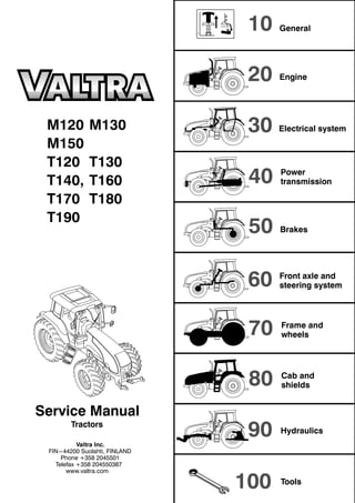
- 1. 10 20 30 40 50 60 70 80 90 100 M120 M130 M150 T120 T130 T140, T160 T170 T180 T190 Tractors Valtra Inc. FIN---44200 Suolahti, FINLAND Phone +358 2045501 Telefax +358 204550387 www.valtra.com General Engine Electrical system Power transmission Front axle and steering system Brakes Frame and wheels Cab and shields Hydraulics Service Manual Tools
- 2. 10. General 11. Layout 12. Construction 13. Maintanance 14. General technical specifications
- 3. Model Code Page 11. Layout 110 1 2.1.2004 T120--T190 M120--M150 7 The following supplements have been published for the Valtra T and M---series Service Manual: Order number Date of publication Notes
- 4. Model Code Page 11. Layout 110 3 2.1.2004 T120--T190 M120--M150 9 Layout of Service Manual Division into groups The manual is divided into groups (10---100) which are based on the make---up of the tractor. The groups are listed on the first index leaf. Example. 10. General 20. Engine, fuel and cooling systems 30. Electrical system 40. Power transmission a.s.o. The number designation for each group is given in the top left box of the respective pages (and the first figure in the code designa- tion). 410 1 50 60 70 80 90 100 Code Page Division into components or sub--groups Each group is further divided into components or sub---groups. The number and the name of each component is given in the top left box on each page (and comprise the two first figures in the code designation). Example. 41. Clutch 42. Gearbox 44. Low gear 45. Final drives etc.
- 5. Model Code Page 11. Layout 110 4 2.1.2004 T120--T190 M120--M150 10 Tractor model At the top of each page it is indicated for which tractor the page is valid. Code designation Three---digit code designations are used to separate the different document groups for the respective components. The same code is also used in the Time list as a reference to the text in this manual. The code designation numbers appear in the box at the top of the page and also in the headings. Example: Code 410 --- Group: power transmission (4) --- Component: clutch (41) --- Document group: general (410) Page numbers The instructions for all components are numbered in consecutive order in the right---hand box at the top of the page. The page numbers begin with page 1 for each component. 41. Clutch 15. 5. 1993 Model Code Page 205---665 410 1 Date At the top of each page there are two boxes for dates. In a case of revised issue, the date of the earlier issue is printed in the crossed---over box and and the date of the current issue is printed in the proper date box. Additions and amendments of the service manual New and up---dated pages will be continuously added to the service manual. The new pages should be inserted as indicated by the code: the first digit (also the first digit on the index leaf) indicates the group: --- the two first digits indicate the component or sub---group. --- the third digit indicates the document group for the respective components --- the page number indicates the definite position of the page within the service manual. If there are two pages with the same code and page number, it is the page with the later date in the date box and the old date in the crossed---over box which is valid or which is the current page. When an entirely new set of repair instructions is issued, it will be accompanied by instructions on where the pages should be inserted in the file.
- 6. Model Code Page 11. Layout 110 5 2.1.2004 T120--T190 M120--M150 11 Code designations in the Service Manual 10. General 110 Layout 120 Repairs 130 Maintenance 20. Engine 21. Engine 210 General 211 Cylinder block 212 Flywheel housing 213 Cylinder head and valve mechanism 214 Crankshaft engine 215 Counterbalance 216 Timing gear assembly 217 Lubrication system 218 Inlet and exhaust system 219 Safety instructions 22. Fuel system 220 General 222 Fuel feed pump and fuel filters 223 Injection pump and injectors 23. Cooling system 230 General 231 Cooling system 24. Engine control system 240 General 241 Changing of control unit 30. Electrical system 31. Autocontrol 5.3 310. Electrical system 311. Wiring diagram 32. Autocontrol 5.5 33. Autocontrol 6.1 330. Electrical system 331. Wiring diagram 34. Service codes 340. Autocontrol system 341. Power lift system 35. Power lift electrical system 350. General 351. Services and fault codes 36. Working hydraulics electrical system 360. General 37. Service software 370. General 40. Power transmission 41. Clutch 410. General 411. Repair instructions of the clutch 42. Gearbox 420. General 421. Repair instructions of the selector forks 423. Repair instructions of the gearbox 424. Repair instructions of the differential 44. Quick---shift gear (DPS) Reverse shuttle 4WD clutch 440. General 441. Repair instructions of the quick---shift gear. (DPS) and reverse shuttle 442. Repair instructions of the 4WD clutch 45. Final drives 450. General 451. Repair instructions of the final drives 46. Power take off 460. General 462. Repair instructions of the rear PTO 462. Repair instructions of the front PTO 50. Brake system 51. Service brakes 510. General 511. Repair instructions of the service brakes 52. Parking brake 521. Repair instructions of the parking brake
- 7. Model Code Page 11. Layout 110 6 2.1.2004 T120--T190 M120--M150 12 60. Front axle and steering system 61. Steering system 610 Technical data, description, tools 611 Reconditioning steering system 612 Priority valve 613 Steering cylinder 62. Powered front axle 620 Technical data, description, tools 621 Axle housing and central pivot bearing brackets 622 Drive shaft 623 Hub reduction gear 624 Differential 63. Powered front axle 630 Technical data, description, tools 64. Powered front axle 640 Technical data, description, tools 642 Drive shafts 643 Hubs 644 Differential 70 Frame and wheels 710 Frame 720 Wheels 80 Cab and shields 90. Hydraulics, power lift 91. Hydraulics 910. General 911. Repair instructions of the hydraulics 92. Valves for auxiliary hydraulics and front loader 920. General 921. Repair instructions of the auxiliary hydraulics 93. Power lift 930 General 931. Repair instructions of the front and rear power lift 100 Special tools
- 8. Model Code Page 12. Construction 120 1 2.1.2004 T120--T190 M120--M150 13 T120---T190 series, construction
- 9. Model Code Page 12. Construction 120 2 2.1.2004 T120--T190 M120--M150 14 M120---M150 series, construction
- 10. Model Code Page 12. Construction 121 1 2.1.2004 T120--T190 M120--M150 15 T120---T190 series, dimensions
- 11. Thank you very much for your reading. Please Click Here Then Get More Information. NOTE: If there is no response to click on the link above, please download the PDF document first and then click on it.
- 12. Model Code Page 12. Construction 121 2 2.1.2004 T120--T190 M120--M150 16 Dimensions (mm) T 120 T 130 T 140 T 160 T 170 T 180, T190 1. With front tyres/tires 16.9R28 16.9R28 16.9R28 460/85R30 460/85R30 460/85R30 2. With rear tyres/tires 20.8R38 20.8R38 20.8R38 20.8R42 20.8R42 20.8R42 4. Length 5148 5148 5148 5148 5148 5148 7a. Width 2338 2338 2338 2338 2338 2338 5a. Height to the roof 2960 2960 2960 3030 3030 3030 5. Height to the exhaust pipe 2900 2900 2900 2965 2965 2910 3. Wheel base 2748 2748 2748 2748 2748 2748 8. Ground clearance (front axle) 555/5151) 555/5151) 555/5151) 600/5601) 600/5601) 600/5601) 9. Ground clearance (rear axle) 535 535 535 600 600 600 1) With front axle suspension. Dimension from the rear axle mid point to the cab roof part is 2093 mm. Weights kg T 120 T 130 T 140 With tyres/tires 16.9R28, 20.8R38 16.9R28, 20.8R38 16.9R28, 20.8R38 Total weight (with full fuel tank and without ballast weights) 5530 5530 5650 Front axle weight (%) 2480 (45) 2480 (45) 2600 (46) Rear axle weight (%) 3050 (55) 3050 (55) 3050 (54) Weights kg T 160 T 170 T 180, T190 With tyres/tires 540/65R30, 650/65R42 540/65R30, 650/65R42 650/65R42, 540/65R30 Total weight (with full fuel tank and without ballast weights) 5950 5950 5990 Front axle weight (%) 2700 (45) 2700 (45) 2740 (46) Rear axle weight (%) 3250 (55) 3250 (55) 3250 (54) Track widths: Front 6. Track width 14.9--28/6, 14.9R28, 380/70R28, 380/85R28, 420/70R28, 420/85R28, 440/65R28, 16.9R28, 16.9--28/8, 480/65R28, 480/65R28E1, 480/70R28, 540/65R28, 540/65R28E1 + more: see operator’s manual 1540, 1635, 1740, 1835, 1940, 2035 Rear 7. Track width 8.4R38, 18.4--38/8, 18.4R42, 460/85R38, 480/70R38, 20.8R38,, 20.8--38/10, 520/70R38, 520/85R38, 520/85R42 540/65R38, 580/70R38, 480/80R42 + more: see operator’s manual 1610, 1715, 1810, 1910, 2010, 2115 Maximum permissible front--- and rear axle loadings, kg Regardless of any limitations due to the tyres/tires, with standard track widths max. speed. Tractor T120, T130 T140---T170 T180,T190 Front 4WD max 40 km/h 3300 max 8 km/h 5500 industrial front axle max 40 km/h 4500 4500 4500 max 8 km/h 6200 6200 6200 Rear, max 40 km/h 8000 9000 9000 Total weight, max 40 km/h 9000 11000 11000
- 13. Model Code Page 12. Construction 121 3 2.1.2004 T120--T190 M120--M150 17 M120---M150 series, dimensions www.agrimanuals.bigcartel.com
- 14. Model Code Page 12. Construction 121 4 2.1.2004 T120--T190 M120--M150 18 Dimensions (mm) M120 M130 M150 1. With front tyres/tires 16.9R28 16.9R28 16.9R28 2. With rear tyres/tires 20.8R38 20.8R38 20.8R38 4. Length 4898 4898 4898 7a. Width 2338 2338 2338 5a. Height to the roof 3000 3000 3000 5. Height to the exhaust pipe 2930 2930 2930 3. Wheel base 2559 2559 2559 8. Ground clearance (front axle) 530/4901) 530/4901) 530/4901) 9. Ground clearance (rear axle) 535 535 535 1) With front axle suspension Dimension from the rear axle mid point to the cab roof part is 2133 mm. Weights kg M120 M130 M150 With tyres/tires 20.8R38 20.8R38 20.8R38 Total weight (with full fuel tank and without ballast weights) 5290 2) 5290 2) 5450 Front axle weight (%) 2320 (44) 2) 2320 (44 2) 2480 (46) Rear axle weight (%) 2970 (56) 2970 (56) 2970 (54) 2) With industrial front axle 160 kg heavier, standard on model M150. Track widths: Front 6. Track width 13.6R28, 14.9R28, 14.9--28, 16.9R28, 16.9--28, 340/85R28, 380/85R28, 420/70R28, 420/85R28, 440/65R28, 480/65R28, 480/70R28, 540/65R28 1530, 1645, 1735, 1840, 1930, 2045, 2135 230/95R36 1504, 1580, 1602, 1702, 1880, 1980, 2002, 2102 14.9R28, 14.9R28 IND, 16.9R28, 14.9--28/14 FOR, 420/85R28, 480/65R28 IND 1840, 1745 Industrial front axle 6. Track width 14.9R28*, 14.9--28*, 16.9R28, 16.9--28, 380/85R28*, 420/70R28*, 420/85R28, 480/65R28, 480/70R28, 540/65R28 1530, 1625, 1730, 1830*, 1930, 2025, 2130, 2230 230/95R36 1500, 1545, 1810, 1855, 1900, 1940, 2210, 2255 500/60--26,5 FOR 1890, 1880 14.9R28, 14.9R28 IND, 14.9--28 FOR, 16.9R28, 16.9R28 IND, 16.9--28 FOR, 1870 1890 14.9R28, 14.9R28 IND, 14.9 28 FOR, 16.9R28, 16.9R28 IND, 16.9 28 FOR, 420/85R28, 480/65R28 IND, 500/65R28 FOR, 540/65R28, 540/65R28 FOR 1870, 1890 Rear 7. Track width 16.9R38, 18.4R38, 18.4--38/8, 420/85R38, 460/85R38 1510, 1610, 1715, 1810, 1910, 2010, 2115 20.8R38, 20.8--38/10, 520/70R38, 520/85R38, 540/65R38, 580/70R38 1610, 1715, 1810, 1910, 2010, 2115 600/65R38, 650/65R38 1715, 1810, 1910, 2010, 2115 270/95R48 1500, 1520, 1600, 1620, 1900, 1920, 2000, 2020 680/75R32 1714, 1810 18.4--38/14 FOR, 18.4R38, 18.4R38 IND 1650, 1875 600/65--34 FOR 1630, 1900 20.8R38, 20.8R38 IND, 20.8--38/14 FOR, 520/85R38, 600/65R38 FOR, 600/65R38 IND, 650/65R38, 650/65R38 FOR 1675, 1850 Maximum permissible front--- and rear axle loadings, kg Regardless of any limitations due to the tyres/tires, with standard track widths max. speed. Tractor M120---M150 max 40 km/h 3300 Front 4WD max 8 km/h 5500 Front 4WD industrial front axle max 40 km/h 4500 Industrial front axle max 8 km/h 6200 Rear, max 40 km/h 8000 Total weight, max 40 km/h 9000
- 15. Model Code Page 13. Maintanance 130 1 2.1.2004 T120--T190 M120--M150 19 General instructions for repairs Outer oil seals The Service Manual contains instructions for changing all outer oil seals, (e.g. oil seals on the PTO shaft end, on the output shaft to the front wheel drive and on the pinion shaft on the powered front axle, and so on). Sealing compound and glue If sealing compounds or glue are required for the repair work, the instructions will specify a sealing compound or glue which is readily available through specialist dealers. Some seals should be greased before fitting and the space between the lips of the seal should be filled with universal grease. If the seal is to be pushed over splines or sharp edges the seal should be protected with for example a thin plastic foil. Tightening torques and setting values All necessary tightening torques and setting values for each repair operation are given at the beginning of each repair section under the heading Technical Data. The most important values can also be found in the repair instructions. Table 1 later gives the tightening torques in order of dimension, quality and surface treatment. The values given in the table should be used if the tightening torque is not given in the repair instructions. Safety Always bear safety in mind when repairing or servicing the tractor. Use tools and lifting devices in the correct way . When you are removing tractor components or splitting the tractor, every tractor part must be supported in such a way, that no risk of accident exists. Avoid working under the supported tractor part if it is not absolutely necessary. When supporting the tractor the centre of gravity of the frame part must always be checked. For instance the wedges must always be fitted between front axle and engine to prevent axle oscillation when splitting the front frame of the tractor. Trouble---shooting The following procedure, combined with the information contained in the workshop manual will be helpful in tracing faults accu- rately. It consists of following a number of logical steps to locate and correct the problem. a) Determine the problem b) List possible causes c) Differentiate the causes d) Conduct checks in logical order to determine the exact cause e) Consider approximate remaining service life against cost of parts and labour. f) Make any necessary repairs. g) Recheck the parts and functions for correct operation