SlideShare a Scribd company logo
1 of 66
Download to read offline
VALTRA – VALMET
MEGA MEZZO HI-TEC
WORKSHOP MANUAL
Service Manual
Tractors
Power
transmission
Brake
system
Steering sys-
tem and Front
axle
Frame and
Wheels
Tools
Cab and
Shields
Hydraulics
Valtra Inc.
44200 Suolahti, Finland
Groups 10---100
General
Engine
Electrical
system
40
50
60
70
80
100
90
6000, 6100, 6200
6250, 6300, 6350
6400, 6550, 6600
6650, 6800, 6850
6900, 8000, 8100
8200, 8400, 8050
8150, 8450, 8550
8750, 8950
6600E---8750E
10
20
30
Order no 39 210 211
ENGLISH
10. General
11. Layout
12. Repairs
13. Maintenance
2
3
To the reader
The Service Manual for the Valmet tractors is intended to be a practical reference source to be used in work-
shop. The repair instructions in the manual are based on methods which have been worked out in practice
during normal workshop conditions and which are based on the use of special tools from the manufacturer
when stated in the instructions. The manual also contains descriptions of the design and function of the
components.
Detailed maintenance instructions can be found in Operator’s Manual.
The Service Manual will be continually updated with new revised pages which should be inserted in the
manual. Alterations and additions will first appear as service bulletins.
Only genuine Valmet spare parts should be used to ensure the best possible function of the machine. Cer-
tain operations should be carried out with the aid of special tools designed by Valmet.
Valmet Tractors Inc.
Tractor Service
4
Model Code Page
11. General 6000--8950 110 01. 9. 2002
1. 8. 2000
The following supplements have been published for the Valmet 6000---8950 Service Manual:
Ordering number Date Notes
39 256 211
39 256 212
39 256 213
39 256 214
39 256 215
39 256 216
39 256 217
39 256 218
39 256 219
39 260 211
39 260 212
39 260 213
39 260 214
39 260 215
15. 6. 1992
1. 9. 1992
15. 5. 1993
1. 1. 1994
1. 1. 1995
15. 4. 1995
15. 5. 1996
1. 4. 1997
1. 8. 1998
1. 11. 1998
1. 6. 1999
1. 10. 1999
1. 8. 2000
1. 9. 2002
Supplement no. 39 256 211 (15. 6. 1992)
Includes:
--- Autocontrol III
--- air conditioning
--- tractor 8000
--- amendments
Supplement no. 39 256 212 (1. 9. 1992)
Includes:
--- 20---series engines
--- amendments
Supplement no. 39 256 213 (15. 5. 1993)
Includes:
--- Delta Powershift
--- tractor 8400
--- amendments
--- the latest fitting instructions of optional equipment
Supplement no. 39 256 214 (1. 1. 1994)
Includes:
--- tractors 6000 and 8200
--- Autocontrol II
--- Autocontrol IV
--- Sige---axle differential lock
--- industrial front axle
--- latest air conditioning
--- amendments
Supplement no. 39 256 215 (1. 1. 1995)
Includes:
--- amendments
--- the latest fitting instructions of optional equipment
Supplement no. 39 256 216 (15. 4. 1995)
Includes:
--- engine intake air system and cooling system, modifications
--- Autocontrol 2.1
--- Agrodata---instrument
--- hydraulic type clutch release mechanism
--- DPS, modifications
Supplement no. 39 256 217 (15. 5. 1996)
Includes:
--- tractor 6800
--- tractors 8050---8750
--- amendments
Supplement no. 39 256 218 (1. 4. 1997)
Includes:
--- tractors 6200 and 8000R
--- front PTO
--- CareTel
--- Hi Shift
--- amendments
--- the latest fitting instructions of optional equipment
Supplement no. 39 256 219 (1. 8. 1998)
Includes:
--- FieldMaster
--- pressure air brakes for trailer (optional)
--- latest fitting instructions for optional equipment
--- amendments
--- new folder, new index leaves (10---30 and40---100) andnew
spine labels.
Supplement no. 39 260 211 (1. 11. 1998)
Includes:
--- HiTech reverse shuttle
--- Autocontrol V
--- New 50---series models
--- Front axle air suspension
--- E---engines
--- Amendments
Supplement no. 39 260 212 (1. 6. 1999)
Includes:
--- Autocontrol 2.2
--- amendments (e.g. for AC V)
--- fitting instructions for optional equipment
Supplement no. 39 260 213 (1. 10. 1999)
Includes:
--- Carraro 20.29 front axle
--- amendments (e.g. version 42 of AC V)
Supplement no. 39 260 214 (1. 8. 2000)
Includes:
--- HiTech gen. 2, AC---5.2
--- front PTO on 6250H---6850Hi tractors
--- modified lubricating oil pump for 6---cyl. engines
--- new rear axle housing for transmissions 650/550
--- amendments
--- updated fitting instructions for optional equipment
Supplement no. 39 260 215 (1. 9. 2002)
Includes:
--- transmission and final drives 700
--- Agroline---instrument
--- technical modifications
6
7
Model Code Page
11. Layout
8. 11. 1990
6000--8750 110 1
Layout of Service Manual
1. Division into groups
The manual is divided intogroups (10---100) which are based on the make---up of the tractor. The groups are listed on the firstindex
leaf.
Example. 10. General
20. Engine, fuel and cooling systems
30. Electrical system
40. Power transmission
a.s.o.
The number designation for each group is given in the top left box of the respective pages (and the first figure in the code designa-
tion)
410 1
50
60
70
80
90
100
Code Page
2. Division into components or sub---groups
Each group is further divided into components or sub---groups. The number and the name of each component is given in the top
left box on each page (and comprise the two first figures in the code designation).
Example. 41. Clutch
42. Gearbox
44. Quick---shift gear
45. Final drives etc.
8
Model Code Page
11. Layout
8. 11. 1990
6000--8750 110 2
3. Code designation
Three---digit code designations are used to distinguish the different document groups for the respective components. The same
code is also used in the Time List as a reference tothe text in this Manual. The code designation numbers appear both in the box at
the top of the page and also in the headings.
Example: Code 410:
--- Group: Power transmission (4)
--- Component: Clutch (41)
--- Document group: General (410)
4. Page numbers
The instructions for all components are numbered in consecutive order in the right---hand box at the top of the page. The page
numbers begin with page 1 for each component.
41. Clutch
15. 5. 1993
Model Code Page
6100---8400 410 1
8. 11. 1990
5. Date
At the top of each page there are two boxes for dates. In the case of a revised issue, the date of the earlier issue is printed in the
crossed---over box and the date of the current issue is printed in the ”real” date box.
6. Model
At the top of each page the tractor model for which the page is valid is indicated.
7. Additions and amendments of the service manual
New and up---dated pages will be continually added to the service manual. The new pages should be inserted as indicated by the
code: the first digit (also the first digit on the index leaf) indicated the group:
--- the two first digits indicate the component or sub---group
--- the third digit indicates the document group for the respective components
--- the page number indicates the definite position of the page within the service manual
If there are two pages with the same code and page number the page with the later date in the date box (and the old date in the
crossed---over box) is valid (or the current page).
N.B. Fitting instructions for extra equipment are inserted into the service manual at the end of group concerned (E.g. code 39 is
inserted at the end of group 30).
9
Model Code Page
11. Layout 6000--8750 110 31. 4. 1997
8. 11. 1990
Code designation in the Service Manual
10. General
110 Layout
120 Repairs
130 Maintenance
20 Engine
21. Engine
210 Technical data, tools, description
211 Cylinder block and flywheel housing
212 Cylinder head and valve mechanism
213 Crank mechanism
214 Timing gears
215 Lubrication system and oil sump
216 Induction and exhaust system, turbocharger
219 Removing and fitting engine
22. Fuel system
220 Technical data, tools, description
222 Fuel feed pump and fuel filters
223 Injection pump and injectors
23. Cooling system
230 Technical data, tools, description
231 Thermostat and coolant pump
30. Electrical system
310 Specifications, wiring diagrams
311 Autocontrol II
312 Autocontrol 2.1
313 Sigma---power
320 AC power lift
321 ACD power lift
330 Agrodata
331 AD---instrument
340 Autocontrol---III
350 Autocontrol IV
360 CareTel
40. Power transmission
41. Clutch
410 Technical data, tools, description
411 Clutch assembly and pedal rods
412 Hydraulic coupling
42. Gearbox
420 Technical data, tools, description
421 Selector forks
422 Gear shift levers
423 Shafts and gear wheels
424 Differential
44. Quick---shift gear, DPS, reverse shuttle, 4WD clutch
440A Quick---shift gear, technical data, tools, description
440B Reverse shuttle, technical data, tools, description
440C 4WD clutch, technical data, tools, description
441 Quick---shift gear, repair instructions
442 Reverse shuttle, repair instructions
443 4WD clutch, repair instructions
444 DPS, repair instructions
45. Final drives
450 Technical data, tools, description
451 Final drives, repair instructions
46 Power take---off
460 Technical data, tools, description
461 Power take---off, repair instructions
463 Front PTO, repair instructions
10
Model Code Page
11. Layout 6000--8750 110 41. 4. 1997
8. 11. 1990
50. Brakes
510 Technical data, description
511. Service brakes
520 Parking brake
60. Steering system and front axle
61. Steering system
610 Technical data, tools, description
611 Steering valve
612 Priority valve
613 Steering cylinder
614 Adjustment
64. Powered front axle
640 Technical data, tools, description
641 Front axle housing and front axle suspension
643 Hubs
644 Differential
645 Industrial front axle
70 Frame and wheels
710 Tractor frame
720 Tyres and wheel discs
80 Cab and shields
810 Cab
820 Shields
830 Air conditioner
90 Hydraulics
910 Technical data, tools, description
911 Pump and pipes
912 Working hydraulics
913 Three---point linkage, towing hook
920 AC power lift
100. Special tools
101 Special tools (ETV)
102 Locally manufactured tools
Note! Separate fitting instructions for the optional equipments are inserted into the Service Manual. These instructions are posi-
tioned to the end of each main group. E.g. code 39 are placed to the end of group 30.
11
Model Code Page
12. Repairs
8. 11. 1990 6000--8750 120 1
General instructions for repairs
Outer oil seals
The Service Manual contains instructions for changing all outer oil seals, (e.g. oil seals on the PTO shaft end, on the output shaft
to the front wheel drive and on the pinion shaft on the powered front axle, and so on).
Sealing compound and glue
If sealing compounds or glue are required for the repair work, the instructions will specify a sealing compound or glue which is
readily available through specialist dealers. Some seals should be greased before fitting and the space between the lips of the
seal should be filled with universal grease. If the seal is to be pushed over splines or sharp edges the seal should be protected
with for example a thin plastic foil.
Tightening torques and setting values
All necessary tightening torques and setting values for each repair operation are given at the beginning of each repair section
under the heading Technical Data. The most important values can also be found in the repair instructions.
Table 1 later gives the tightening torques in order of dimension, quality and surface treatment. The values given in the table should
be used if the tightening torque is not given in the repair instructions.
Safety
Always bear safety in mind when repairing or servicing the tractor. Use tools and lifting devices in the correct way . When you
are removing tractor components or splitting the tractor, every tractor part must be supported in such a way, that norisk of accident
exists. Avoid working under the supported tractor part if it is not absolutely necessary. When supporting the tractor the centre of
gravity of the frame part must always be checked. For instance the wedges must always be fitted between front axle and engine
to prevent axle oscillation when splitting the front frame of the tractor.
Trouble---shooting
The following procedure, combined with the information contained in the workshop manual will be helpful in tracing faults accu-
rately. It consists of following a number of logical steps to locate and correct the problem:
a) Determine the problem
b) List possible causes
c) Differentiate the causes
d) Conduct checks in logical order to determine the exact cause
e) Consider approximate remaining service life against cost of parts and labour..
f) Make any necessary repairs.
g) Recheck the parts and functions for correct operation
12
Model Code Page
12. Repairs
8. 11. 1990 6000--8750 120 2
Handling of heavy components
Unless otherwise specified, all removals should be accom-
plished using adjustable lifting equipment. All supporting
slings must be parallel to each other and as near vertical as
possible in relation to the object being lifted. However, where
slings are of a far greater capacity than the weight of the load
to be fitted, a triangular lifting arrangement may be used.
Oikein
Rätt
Right
Richtig
Giusto
Väärin
Fel
Wrong
Falsch
Sbagliato
Correct
Teisingai
Mauvais
Netei-
singai
When removing a component at an angle, remember that the
capacity of an eyebolt is reduced when the angle between the
supporting members and the object becomes less than 90˚.
B
C
D
A
Forged eyebolt support
A. Load
B. Lifting shackle
C. Shackle retaining plate ( 3 mm thick)
D. Sleeve
When necessary the forged eyebolt can be supported in the
way shown in figure above. Sleeve D may or may not be
welded to plate.
Warning! If a part resists removal, check that allnuts andbolts
have been removed and that there is no interference from ad-
jacent parts.
Cleanliness
Toensure long life of a machine, it is important tokeep dirt and
foreign material out of its vital working components. Precau-
tions must be taken to safeguard against this. Enclosed com-
partments, seals and filters have been provided to keep the
supply of air, fuel and lubricant clean. These protective de-
vices must not be removed.
Whenever hydraulic, fuel, lubricating oil or lines are discon-
nected, clean the point of disconnection and the surrounding
area. As soon as a line has been disconnected, cap, plug or
tape the line or opening to prevent the ingress of foreign ma-
terial.
The same cleaning and covering precautions should be taken
when access covers or inspection plates are removed.
Clean and inspect all parts. Make sure that all passages and
holes are clear. Cover all parts to keep them clean. Make sure
parts are clean when they are reassembled. Leave new parts
in their wrapping until they are actuallyneeded forreassembly
Assembly
When reassembling a machine, complete each step in se-
quence. never partially assemble one part then start to as-
semble another. Make all recommended adjustments. Al-
ways check the job on completion to ensure that nothing has
been overlooked. Recheck the various adjustments before
putting the machine back into service.
Note! Before fitting new parts, remove rust preventative com-
pound from all machined surfaces (usually ”peel---off sub-
stances).
Lubrication
Where applicable, fill the compartments of repaired or re-
newed components with the quantity, type and grade of clean
lubricant recommended in the routine maintenance section of
the Operator’s Manual.
Shims
When shims are removed, tie them together and identify their
location. Keep shims clean and take care not to bend them
before refitting them.
Gaskets
Make sure that the holes in gaskets line up with lubricating oil
passages in the mating parts. If gaskets have tobe made, use
material of the correct type and thickness. Make sure that
holes are punched in the right places.
Incorrectly punched gaskets can cause serious damage.
Lip type rubber seals
Lubricate the lips of lip---type rubber seals with oil before fit-
ment. Do not use grease on seals, except for grease seals.
13
Model Code Page
12. Repairs
8. 11. 1990 6000--8750 120 3
4
5
3
2
1
The main parts of lip---type seal:
1. Case
2. Sealing element
3. Ring spring
The figure above shows the construction of a simple lip---type
seal. The cross section shows the heel (4) and the toe (5),
used to identify the sides of a single element seal. With a few
exceptions, the toe of a single---lip is located on the lubricant
side. Some seals have a second auxiliary lip which has no
spring.
Cables and wires
When removing or disconnecting a group of cables or wires,
label each one to ensure correct refitment.
Locking devices
Correct and incorrect use of retainers
Correct and incorrect method of fitting and bending locking
tabs.
Slackening of nuts and bolts is prevented by mechanical
means such as lockwashers, tab washers and cotter pins, or
by Loctite---type locking agents.
Flat retainers must be installed properly to be effective. Bend
one end of the retainer against the edge of the part. Bend the
other end against one of the nut or bolt head.Always fit new
retainers in compartments which house moving parts. When
fitting lockwashers on aluminium housings, place a flat
washer between the lockwasher and the housing.
Note!
1) Never fit a lockwasher (Grower, fan, spring, etc.)under anut
or bolt to which a specified torque has to be applied.
2) Always thoroughly degrease components before applying
Loctite type locking agents.
Bushes and press fits
Do not fit bushes with a hammer alone. Use a suitable fitting
tool and a hammer or, better still, a press if possible..
When using a press, ensure that pressure is applied directly
in line with the bore. If the ring has an oil hole, take care toalign
it with the oil hole in the mating part. When press fitting a part
into another part, lubricate the mating surfaces. Tapered parts
should be assembled dry. Before assembly, check that the
tapers are dry and free from burrs.
Fitting bolts in blind holes
Use bolts of the correct length. A bolt which is too long may
”bottom” before the head comes into contact with the part it
is to hold: this will cause damage to the threads. If a bolt is too
short, there may not be enough threads engaged to hold the
part securely.
14
Model Code Page
12. Repairs
8. 11. 1990 6000--8750 120 4
Table
Table 1. Tightening torques, metric standard thread (ISO)
Tightening torques Nm1)
Dim. Quality, surface treatment, material and so on
8.8
lubr. tol.±
8.8
Zne2) tol±
8.8
Znk3) tol. ±
10.9
lubr. tol. ±
12.9
lubr tol. ±
M4 --- --- --- --- ---
M5 6,4 0,6 5,7 0,5 --- 9 1 11 1
M6 11 1 10 1 12 1,2 15 1,5 18 2
M8 25 2 23 2 30 3 35 4 45 5
M10 50 5 45 5 60 5 70 7 90 10
M12 90 10 80 8 100 10 125 10 151 15
M14 140 15 125 10 160 15 200 20 240 20
M16 220 20 195 20 250 25 300 30 370 40
M18 300 30 270 30 350 35 430 40 510 50
M20 430 40 380 40 480 50 600 60 720 70
M22 570 60 500 50 650 65 800 80 970 100
M24 740 70 660 70 830 80 1030 100 1250 120
M27 1100 100 950 100 1200 120 1500 150 1800 180
M30 1500 150 1300 130 1600 160 2040 200 2500 250
1) 1 Nm=0,102 kpm
2) Zne=zinc electroplating
3) Znk=hot galvanized
If the bolts differs from the standard range the values in the
table must not be used.
15
Model Code Page
12. Repairs
8. 11. 1990 6000--8750 120 5
Conversion table for common units
Quantities and units Conversion factors
Overall and detail dimensions millimetres (mm) 100 mm=3,94 inches
1 inch=25,4 mm
Short distances e.g. turning circles metres (m) 1 m=3,28 ft
1 ft=0,305 m
Travel distances kilometres 1 km=0,62 mile
1 mile=1,61 km
Tractor weights, axle loadings kilograms (kg) 1 kg=2,2 lbs
1 lb=0,454 kg
Travel speed kilometres per h (km/h) 1 km/h=0,62 mph
1 mph=1,61 km/h
Drawbar pull kilonewtons (kN) 1 kN=224,8 lbs
1 lb=4,448 N
Power (identified by such terms as crankshaft power, 1 kW=1,34 hp
pto power, belt power, drawbar power, indicating 1 hp=0,746 kW
the point at which the measurement was taken)
kilowatts (kW)
Engine torque newton metres (Nm) 1 Nm=0,74 ft lb
1 ft lb=1,356 Nm
Fuel consumption by weight (kilograms per hr, kg/h) 1 kg/h=2,2 lb/hr
(by volume) litres per hr (l/h) 1 lb=0,454 kg
1 l/h=0,22 gal/hr
1 gal=4,54 l
Fuel economy (specific fuel consumption) 304 g/kWh=0,5 lb/hp hr
grams per kilowatt hr (g/kWh)
Engine displacement litres (l) 1 l=61,02 m cu in
100 cu in=1,639 l
Hydraulic pump 1 MPa=145 psi
pressure---mecapascal (MPa) 1000 psi=6,9 MPa
delivery---millimetres per sec (ml/s) 100 ml/s=1,32 gpm
1 gpm=75,77 ml/s
Tyre
pressure---kilopascal (kPa) 100 kPa=14,5 psi
1 psi=6,9 kPa
Area acres---hectare To convert multiply by
0,404686
Volume bushel---litre To convert multiply by
39,3687
Quantity pound per acre---kilogram per hectare Multiply by 1,12085
Volume Multiply by
superficial foot---cubic metre 0,002360
16
17
Model Code Page
13. Maintenance
15. 5. 1996 6000--8750 130 1
1. 1. 1994
Maintenance Valmet 6000---8750
N.B. Detailed maintenance instructions, see Operator’s Man-
ual.
General
Correct maintenance at the right time is a basic condition for
reliable operation of the tractor. Maintenance costs are small
compared with any repair costs resulting from lack of main-
tenance. The most important measures are those which you
carry out yourself and which include lubrication and various
checks and adjustments.
The service intervals shown apply for normal operating condi-
tions but in more severe conditions servicing should be car-
ried out more frequently.
General instructions concerning oil
checks and oil filling
--- Always stop the engine before starting work
--- Apply the parking brake to ensure the tractor cannot
move. If the ground is uneven the wheels should be
scotched
--- Wash down the tractor first so that the work can be done
more easily and quickly.
--- Always observe the utmost cleanliness in all mainten-
ance work. Thoroughly wipe off filler caps and plugs as well
as surrounding parts of the tractor before filling up with fuel
or oil.
--- Inspect the oil and filters when changing. Large
amounts of dirt (e.g. heavily clogged filters) can point to a
fault which could cause extensive and costly repairs if not
corrected in time.
---When carrying out checks the tractor should stand on level
ground.
--- Levels should be checked in the morning when the oil
is cold and has had time torun down tothe bottom of the unit
concerned.
--- When changing the oil, bear in mind that the oil can be
very hot when it drains from the tractor. Waste oil and oil
filters should be handled carefully and disposed of properly
--- After completion of the service work always replace all
safety covers etc.
Greasing lubricating points fitted with
grease nipples
--- Always clean the grease nipples before applying the
grease gun.
--- Apply grease through the nipples until clean grease
oozes out (unless otherwise instructed).
--- Wipe away superfluous grease which has been
pressed out at the lubricating point.
--- Preferably carry out lubrication with bearing points and
joints unloaded and with the bearings in different positions.
Lubrication and maintenance schedule
All intervals are counted from zerohours on the hour recorder.
For example, 1000 hours service is carried out every 1000
(yearly), 2000 hours (every other year) etc. even if the guaran-
tee service has been carried out.
Example: The 1000 hour service contains all itemsmentioned
under 10 h/Daily, 50 h/once a week, 250 h, 500 h and 1000 h.
18
Model Code Page
13. Maintenance
1. 4. 1997 6000--8750 130 2
15. 5. 1996
Maintenance schedule
4
5
614
14
15
15
6084---67
6
6 6
1
14
2
4
5
6
7
8 910
11 12 1415
16 17
18
Daily/every 10 hours
1. Check engine oil level
2. Check coolant level and radiator fins
3. Check for leakage
Weekly/every 50 hours
4. Grease three---point linkage and towing hook
5. Grease brake mechanism (EP grease)
6. Grease front axle brackets (also nipples on steering system
and on non---powered front axle)
7. Check oil level in transmission and hydraulics
8. Clean air filter cyclone (tractors with a horizontally fitted air
filter and an ejector pipe; clean suction housing hole plate)
9. Check fan belt tightness
10.Check water trap (on 6---cylinder engines. On other mo-
dels on the other side. On models 8200, 8400 and
8050---8750 also under both fuel filters)
11.Check electrolyte level in battery
Every 250 hours
12. Clean engine air filter
13. Grease door and window hinges and locks
14. Change engine oil and filter
15. Grease front axle joints (powered axle)
16. Change pressure filters. First change at 100 hours war-
ranty service, then at 250 hours and after that at 500 hours
and then at intervals of 500 running hours.
17. Check brake fluid level (and clutch fluid level,
668103---)
18. Clean cab ventilation air filter
19. Check wheel nuts and bolts and tyre pressures
19
Model Code Page
13. Maintenance
1. 11. 1998 6000--8750 130 3
1. 4. 1997
6084---68
27 30 25 34 22 27 29 31 36 28 33
26
24
39
35 36 32
30 25 38 21 23 37 20 41 33 24
26
42 40 43 33 32
25
Every 500 hours
20. Clean water trap (fuel system) (on 6---cylinder engines.
On the other models on the other side. On models
8200, 8400 and 8050---8750 also under the fuel filters).
Does not concern 6200 and 8000R tractors.
21. Check brake pedal free travel
22. Check clutch pedal free travel, ---668102.
23. Change pressure filters (transmission and hydraulics)
24. Check oil level in front axle differential and hubs
24a. Calibrate first time gaspedal on HiTech models. Later at
intervals of 1000 running hours.
Every 1000 hours/yearly
25. Change oil in transmission/hydraulics and clean suc-
tion strainer
26. Change oil in front axle differential and hubs
27. Change cab ventilation air filter and wash cab recircula-
tion filter, if fitted.
28. Change fuel filters. 6200, 8000R: change also the water
trap filter
29. Change safety filter (in engine air filter)
30. Grease rear drive axle bearings
31. Grease flywheel ring gear
32. Check, grease and adjust front wheel bearings on
non---powered front axle
33. Check/adjust front wheel toe---in
34. Clean fuel tank
35. Adjust valves
35a Calibrate gas pedal on HiTech models
Every 2000 hours/every other year
36. Change engine coolant
37. Change brake fluid (and clutch fluid, 668103---)
38. Change transmission housing breather
39. Check and clean injectors
40. Check alternator
41. Check starter motor
Every 4000 hours
42. Check function of turbocharger at authorized workshop (if
fitted)
43. Change engine rubber vibration damber on 6---cyl.
engines (not 8200 and 8450---8750)
4
Model Code Page
13. Maintenance 6000--8950 130 41. 9. 2002
1. 8. 2000
Recommended fuel and lubricants (all capacities are incl. of filters)
Part of machine SAE---grade API---grade Capacity (litres)
Engine:
--- 6100 (3---cyl.)
15W40 +40˚C 10˚C CG 4
10
--- 6000, 6200---6650Hi, 6800---6850Hi (4---cyl.)
15W40 +40˚C...---10˚C
10W/30 +30˚C...---20˚C
CG---4
CH---4 13
-- 6900, 8000, 8100, 8200, 8400, 8050--8950Hi (6--cyl.)
10W/30 +30 C...---20 C CH---4
19
Hydraulics/transmission HT 60: ---30˚C...+30˚C
HT 100: ---10˚C...+40˚C
GL---4
(G2---98)
34 (43 max/HiTech, 8050---,
J02316---: 45 max)
(extra max 50/HiTech,
8050---, J02316---: extra max
53).
6200---8950 *): min 45, max
55, extra max 65.
8950Hi **): min 45, max 55,
extra max. 65.
Powered front axle:
--- differential, Dana / ind. Carraro 8 / 6
--- hubs, Dana 80W/90 GL---5 (LS) 2x1
--- hubs, ind. front axle Dana+Carraro 2x1,5
Fuel tank:
--- 6000---8000 Hi Trol, 6250Hi---6650Hi HiTrol 158
--- other models diesel fuel 165
--- extra fuel reservoir, metallic / plastic +82 / +121
Cooling system:Cooling system:
--- 6100 (with larger radiator) 13,5 (17,5)
--- 6000, 6200---6600 (with openable front grille) 15,5 (17)
--- 6250 Hi---6650 Hi 17
--- 6800 / 6850 Hi
water+anti---freeze agent (standardi ASTM
22 / 22
--- 8000---8400 (with openable front grille)
water+anti---freeze agent (standardi ASTM
D3306---86a tai BS 6580:1985) 24 (25)
--- 8200, 8400, 8050, 8150 with expansion tank
)
28 (8400, model 2001:
30)
--- 8050 Hi and 8150 Hi 28
--- 8450, 8550 / 8450 Hi, 8550 Hi 25 / 27
--- 8750 / 8950Hi 31 / 31
Brake fluid reservoir/Clutch fluid resesvoir brake fluid SAE J1703 0,3 / 0,2
Window washer reservoir washer fluid 3
Oils in front PTO units see page 463/9.
*) Tractor frame numbers, see page 450/6.
**) Tractor frame numbers, see page 450/8.
Oil quality and capacity in fluid couplings (Hi---Trol)
Voith TD---VA coupling used up to serial no 658205 and Voith TD---FVA1 from serial no 666066. Engine oil SAE 10W/30 year
around or automatic transmission fluid ATF which meets standards: GM type A Suffix A, GM Dexron II (e.g. Neste ATF---X):
---658205 666066---
--- 6000, 6100 --- 7,20 litres
--- 6200, 6300 7,4 litres 6200: 7,35 litres. 6300: 7,45 litres. 6250Hi: 7,40 litres. 6350Hi: 7,80 litres.
--- 6400 7,6 litres 7,85 litres. 6550Hi: 7,90 litres.
--- 6600 7,8 litres 7,90 litres. 6650Hi: 8,00 liter
--- 6800, 8000R, 8000 6800: 8,40 litres. 6900, 8000: 8,00 litres. 6850Hi: 8,00 litres.
Transfluid---coupling with effect from tractor serial no 658206 up to tractor serial no 666065. Engine oil SAE 10W/30 year around
or automatic transmission fluid ATF which meets standards: GM type A Suffix A, GM Dexron II (e.g. Neste ATF---X):
658206--- 659409---666065
659408 *)
--- 6100 5,2 l 6,4 l
--- 6300 5,4 l 6,6 l
--- 6400 5,6 l 6,8 l
--- 6600, 8000 5,8 l 7,0 l
*) Check the manufacturing date of the coupling. If it is 1292 or later, use larger filling quantities.
20. Engine
21. Engine
22. Fuel system
23. Cooling system
21
22
23
Model Code Page
21. Engine
1. 9. 1992 6000--8750 210 1
15. 6. 1992
Contents
General (Op. no. 210):
Specifications 3. . . . . . . . . . . . . . . . . . . . . . . . . . . . . . . . . . . . . . . . . . . . . . . . . . . . . . . . . . . . . . . . . . .
Special tools 10. . . . . . . . . . . . . . . . . . . . . . . . . . . . . . . . . . . . . . . . . . . . . . . . . . . . . . . . . . . . . . . . . . . .
Engine, description 12. . . . . . . . . . . . . . . . . . . . . . . . . . . . . . . . . . . . . . . . . . . . . . . . . . . . . . . . . . . . . .
Repair instructions
Cylinder block and flywheel housing (Op. no. 211):
1. Cylinder block and cylinder liners:
A. Measuring cylinder liner wear 1. . . . . . . . . . . . . . . . . . . . . . . . . . . . . . . . . . . . . . . . . . . . . . . . . . .
B. Removing cylinder liners 1. . . . . . . . . . . . . . . . . . . . . . . . . . . . . . . . . . . . . . . . . . . . . . . . . . . . . . . .
C. Checking cylinder block 1. . . . . . . . . . . . . . . . . . . . . . . . . . . . . . . . . . . . . . . . . . . . . . . . . . . . . . . .
D. Changing camshaft bushing 1. . . . . . . . . . . . . . . . . . . . . . . . . . . . . . . . . . . . . . . . . . . . . . . . . . . .
E. Oversize bushings for camshaft 2. . . . . . . . . . . . . . . . . . . . . . . . . . . . . . . . . . . . . . . . . . . . . . . . .
F. Fitting plug at rear end of camshaft 3. . . . . . . . . . . . . . . . . . . . . . . . . . . . . . . . . . . . . . . . . . . . . . .
G. Fitting pipe for oil dipstick 4. . . . . . . . . . . . . . . . . . . . . . . . . . . . . . . . . . . . . . . . . . . . . . . . . . . . . .
H. Fitting cylinder liners 4. . . . . . . . . . . . . . . . . . . . . . . . . . . . . . . . . . . . . . . . . . . . . . . . . . . . . . . . . . .
2. Flywheel housing:
A. Fitting flywheel housing 6. . . . . . . . . . . . . . . . . . . . . . . . . . . . . . . . . . . . . . . . . . . . . . . . . . . . . . . .
B. Changing crankshaft rear oil seal 6. . . . . . . . . . . . . . . . . . . . . . . . . . . . . . . . . . . . . . . . . . . . . . . .
C. Changing flywheel starter gear 7. . . . . . . . . . . . . . . . . . . . . . . . . . . . . . . . . . . . . . . . . . . . . . . . . .
D. Fitting flywheel 7. . . . . . . . . . . . . . . . . . . . . . . . . . . . . . . . . . . . . . . . . . . . . . . . . . . . . . . . . . . . . . . .
Cylinder head and valve mechanism (Op. no. 212):
1. Cylinder head:
A. Removing cylinder head 1. . . . . . . . . . . . . . . . . . . . . . . . . . . . . . . . . . . . . . . . . . . . . . . . . . . . . . . .
B. Removing valves 1. . . . . . . . . . . . . . . . . . . . . . . . . . . . . . . . . . . . . . . . . . . . . . . . . . . . . . . . . . . . . .
C. Checking cylinder head 1. . . . . . . . . . . . . . . . . . . . . . . . . . . . . . . . . . . . . . . . . . . . . . . . . . . . . . . .
D. Changing valve guides 2. . . . . . . . . . . . . . . . . . . . . . . . . . . . . . . . . . . . . . . . . . . . . . . . . . . . . . . . .
E. Machining valve seat 2. . . . . . . . . . . . . . . . . . . . . . . . . . . . . . . . . . . . . . . . . . . . . . . . . . . . . . . . . . .
F. Changing valve seat inserts 3. . . . . . . . . . . . . . . . . . . . . . . . . . . . . . . . . . . . . . . . . . . . . . . . . . . . .
G. Grinding valves 3. . . . . . . . . . . . . . . . . . . . . . . . . . . . . . . . . . . . . . . . . . . . . . . . . . . . . . . . . . . . . . .
H. Fitting valves 3. . . . . . . . . . . . . . . . . . . . . . . . . . . . . . . . . . . . . . . . . . . . . . . . . . . . . . . . . . . . . . . . .
I. Fitting cylinder head 4. . . . . . . . . . . . . . . . . . . . . . . . . . . . . . . . . . . . . . . . . . . . . . . . . . . . . . . . . . . .
2.Valve mechanism:
A. Reconditioning rocker arm mechanism 5. . . . . . . . . . . . . . . . . . . . . . . . . . . . . . . . . . . . . . . . . . .
B. Changing camshaft/camshaft gear 5. . . . . . . . . . . . . . . . . . . . . . . . . . . . . . . . . . . . . . . . . . . . . . .
C. Adjusting valve clearance 6. . . . . . . . . . . . . . . . . . . . . . . . . . . . . . . . . . . . . . . . . . . . . . . . . . . . . . .
Crank mechanism (Op. no. 213):
1. Crankshaft:
A. Removing crankshaft 1. . . . . . . . . . . . . . . . . . . . . . . . . . . . . . . . . . . . . . . . . . . . . . . . . . . . . . . . . .
B. Checking crankshaft 1. . . . . . . . . . . . . . . . . . . . . . . . . . . . . . . . . . . . . . . . . . . . . . . . . . . . . . . . . . .
C. Changing crankshaft gears 1. . . . . . . . . . . . . . . . . . . . . . . . . . . . . . . . . . . . . . . . . . . . . . . . . . . . .
D. Changing crankshaft ring gear (420---engines) 2. . . . . . . . . . . . . . . . . . . . . . . . . . . . . . . . . . . . .
E. Fitting crankshaft 2. . . . . . . . . . . . . . . . . . . . . . . . . . . . . . . . . . . . . . . . . . . . . . . . . . . . . . . . . . . . . .
2. Connecting rods and pistons:
A. Removing piston together with connecting rod 3. . . . . . . . . . . . . . . . . . . . . . . . . . . . . . . . . . . . .
B. Changing connecting rod bearings 3. . . . . . . . . . . . . . . . . . . . . . . . . . . . . . . . . . . . . . . . . . . . . . .
C. Checking connecting rod 3. . . . . . . . . . . . . . . . . . . . . . . . . . . . . . . . . . . . . . . . . . . . . . . . . . . . . . .
24
Model Code Page
21. Engine
1. 9. 1992 6000--8750 210 2
15. 6. 1992
D. Connecting rods, weight classes 4. . . . . . . . . . . . . . . . . . . . . . . . . . . . . . . . . . . . . . . . . . . . . . . . .
E. Changing piston rings 5. . . . . . . . . . . . . . . . . . . . . . . . . . . . . . . . . . . . . . . . . . . . . . . . . . . . . . . . . .
F. Checking piston 6. . . . . . . . . . . . . . . . . . . . . . . . . . . . . . . . . . . . . . . . . . . . . . . . . . . . . . . . . . . . . . .
G. Fitting piston pin 6. . . . . . . . . . . . . . . . . . . . . . . . . . . . . . . . . . . . . . . . . . . . . . . . . . . . . . . . . . . . . .
H. Fitting piston together with connecting rod 6. . . . . . . . . . . . . . . . . . . . . . . . . . . . . . . . . . . . . . . .
3. Balancer unit, 420---engines:
A. Removing and dismantling balancer unit 7. . . . . . . . . . . . . . . . . . . . . . . . . . . . . . . . . . . . . . . . . .
B. Reconditioning balancer unit 7. . . . . . . . . . . . . . . . . . . . . . . . . . . . . . . . . . . . . . . . . . . . . . . . . . . .
C. Fitting balancer unit 8. . . . . . . . . . . . . . . . . . . . . . . . . . . . . . . . . . . . . . . . . . . . . . . . . . . . . . . . . . . .
Engine timing gears (Op. no. 214)
A. Removing timing gear casing 1. . . . . . . . . . . . . . . . . . . . . . . . . . . . . . . . . . . . . . . . . . . . . . . . . . .
B. Reconditioning idler gear 1. . . . . . . . . . . . . . . . . . . . . . . . . . . . . . . . . . . . . . . . . . . . . . . . . . . . . . .
C. Fitting timing gear casing 2. . . . . . . . . . . . . . . . . . . . . . . . . . . . . . . . . . . . . . . . . . . . . . . . . . . . . . .
Lubrication system and oil sump (Op. no. 215):
A. Reconditioning oil relief valve for lubrication oil pressure 1. . . . . . . . . . . . . . . . . . . . . . . . . . . . .
B. Removing and dismantling lubricating oil pump 1. . . . . . . . . . . . . . . . . . . . . . . . . . . . . . . . . . . .
C. Assembling and fitting lubricating oil pump 2. . . . . . . . . . . . . . . . . . . . . . . . . . . . . . . . . . . . . . .
D. Fitting oil sump gasket 2. . . . . . . . . . . . . . . . . . . . . . . . . . . . . . . . . . . . . . . . . . . . . . . . . . . . . . . . .
E. Lubricating oil quality requirements 3. . . . . . . . . . . . . . . . . . . . . . . . . . . . . . . . . . . . . . . . . . . . . .
Inlet and exhaust system, turbocharger (Op. no. 216):
A. Checking air filter 1. . . . . . . . . . . . . . . . . . . . . . . . . . . . . . . . . . . . . . . . . . . . . . . . . . . . . . . . . . . . . .
B. Checking inlet and exhaust system 1. . . . . . . . . . . . . . . . . . . . . . . . . . . . . . . . . . . . . . . . . . . . . . .
C. Checking turbocharger 1. . . . . . . . . . . . . . . . . . . . . . . . . . . . . . . . . . . . . . . . . . . . . . . . . . . . . . . . .
D. Reconditioning turbocharger 3. . . . . . . . . . . . . . . . . . . . . . . . . . . . . . . . . . . . . . . . . . . . . . . . . . . .
E. Fitting turbocharger 5. . . . . . . . . . . . . . . . . . . . . . . . . . . . . . . . . . . . . . . . . . . . . . . . . . . . . . . . . . . .
Working orders (Op. no. 219) 1. . . . . . . . . . . . . . . . . . . . . . . . . . . . . . . . . . . . . . . . . . . . . . . .
5
1. 9. 2002
6000--6800 210 3
1. 8. 2000
Model Code Page
21. Engine
Specifications
Engine designations
1. Basic markings: 320, 420, 620 and 634. The first digit indicates the number of cylinders and the two last digits the stroke
(---20=120 mm, ---34=134 mm).
2. Letters after the basic markings:
--- D=diesel engine
--- S=turbocharger (Schwitzer)
--- W=by--pass turbocharger, Delta turbo (Schwitzer S1BG or S2BG)
--- B=Bosch P in---line pump
--- R=distributor pump (Stanadyne)
--- I=intercooler
--- E=low emission engines (E---engines)
--- C=emission tested engines (certificated).
Note! R24, E77 and EPA---homologations has been made for E---engines.
Tractor 6000 6100 6200 6200 6250 Hi 6300 6300
(---K41123) (K41124---) (K41309---
---L23437)
Designation 420D 320 DS 420DSRE 420DSRE 420DSRE 420 DS 420DS
Turbocharger no yes yes yes yes yes yes
No of cylinders 4 3 4 4 4 4 4
Displacement (litres) 4,4 3,3 4,4 4,4 4,4 4,4 4,4
Cyl. bore (mm) 108 108 108 108 108 108 108
Stroke (mm) 120 120 120 120 120 120 120
Compr. ratio 16,5:1 16,5:1 16,5:1 16,5:1 16,5:1 16,5:1 16,5:1
Output (kW/r/min DIN) 55/2300 58/2300 59/2225 59/2200 59/2200 62,5/2225 66/2200
Torque (Nm/r/min DIN) 290/1450 310/1550 320/1400 360/1400 360/1400 330/1550 360/1400
Moment rise % 27 28,5 27 41 41 23 25
Low idling (r/min) 750 800 750 750 850 750 750
Compr. press 1) (bar) 24 24 24 24 24 24 24
Max. no--load revs (r/min) 2500 2500 2425 2400 2400 2425 2400
Tractor 6300 6350 Hi 6400 6400 6400 6400
(L23438---) (J17109---) (K41106---) (L23506---)
(Delta) (Delta)
Designation 420DSRE 420DSRE 420 DS 420 DW 420DW 420DWRE
Turbocharger yes yes yes yes yes yes
No of cylinders 4 4 4 4 4 4
Displacement (litres) 4,4 4,4 4,4 4,4 4,4 4,4
Cyl. bore (mm) 108 108 108 108 108 108
Stroke (mm) 120 120 120 120 120 120
Compr. ratio 16,5:1 16,5:1 16,5:1 16,5:1 16,5:1 16,5:1
Output (kW/r/min DIN) 66/2200 66/2200 70/2225 70/2225 73,5/2200 73,5/2200
Torque (Nm/r/min DIN) 400/1400 400/1400 365/1550 390/1550 415/1400 430/1400
Moment rise % 39 39 22 31 30 35
Low idling (r/min) 750 850 750 750 750 750
Compr. press 1) (bar) 24 24 24 24 24 24
Max. no--load revs (r/min) 2400 2400 2425 2425 2400 2400
Tractor 6550 Hi 6600 6600E 6650 Hi 6750Hi*) 6800 6800E
Designation 420DWRE 420 DS 420 DS 420DWRE 420DWRIE 420 DWI 420DWI
Turbocharger yes yes yes yes yes (+interc..) yes (+interc..) yes (+interc..)
No of cylinders 4 4 4 4 4 4 4
Displacement (litres) 4,4 4,4 4,4 4,4 4.4 4,4 4,4
Cyl. bore (mm) 108 108 108 108 108 108 108
Stroke (mm) 120 120 120 120 120 120 120
Compr. ratio 16,5:1 16,5:1 16,5:1 16,5:1 16,5:1 16,5:1 16,5:1
Output (kW/r/min DIN) 73,5/2200 77/2225 77/2225 81/2200 77/1800 85/2225 85/2225
Torque (Nm/r/min DIN) 430/1400 405/1550 405/1550 460/1400 530/1150 440/1550 440/1550
Moment rise % 35 22 22 31 29 21 21
Low idling (r/min) 850 850 850 850 800 850 850
Compr. press 1) (bar) 24 24 24 24 24 24 24
Max. no--load revs (r/min) 2400 2425 2425 2400 2000 2425 2425
1) Minimum value at operating temperature and starting revs. Max permitted difference between cylinders 3,0 bar.
*) Low revs engine.
E = AC---4, Control system for tractor.
Hi = HiTech.
6
1. 9. 2002
6800--8400 210 3A
1. 8. 2000
Model Code Page
21. Engine
Specifications
Tractor 6800 6850 Hi 6900 8000 8050 8050
(L23517---) (---L23317) (L23318---)
Designation 420 DWRIE 420 DWRIE 620 DRE 620 D 620 DSR 620DSRE
Turbocharger yes (+interc..) yes (+interc..) no no yes yes
No of cylinders 4 4 6 6 6 6
Displacement (litres) 4,4 4,4 6,6 6,6 6,6 6,6
Cyl. bore (mm) 108 108 108 108 108 108
Stroke (mm) 120 120 120 120 120 120
Compr. ratio 16,5:1 16,5:1 16,5:1 16,5:1 16,5:1 16,5:1
Output (kW/r/min DIN) 88/2200 88/2200 75/2225 73,5/2225 81/2200 81/2200
Torque (Nm/r/min DIN) 490/1400 490/1400 390/1400 380/1550 490/1300 490/1400
Moment rise % 28 28 21 20 39 21
Low idling (r/min) 850 850 750 750 750 850
Compr. press 1) (bar) 24 24 24 24 24 24
Max. no--load revs (r/min) 2400 2400 2425 2425 2400 2425
Tractor 8050 Hi 8100 8100E 8150 8150E 8150 8150 Hi
(---L24138) (L24139---)
Designation 620DSRE 620 D 620 D 620 DSR 620 DSR 620DSRE 620DSRE
Turbocharger yes no no yes yes yes yes
No of cylinders 6 6 6 6 6 6 6
Displacement (litres) 6,6 6,6 6,6 6,6 6,6 6,6 6,6
Cyl. bore (mm) 108 108 108 108 108 108 108
Stroke (mm) 120 120 120 120 120 120 120
Compr. ratio 16,5:1 16,5:1 16,5:1 16,5:1 16,5:1 16,5:1 16,5:1
Output (kW/r/min DIN) 81/2200 88/2225 88/2225 92/2200 92/2200 92/2200 92/2200
Torque (Nm/r/min DIN) 490/1400 455/1550 455/1550 540/1300 540/1300 540/1400 540/1400
Moment rise % 39 21 21 35 35 35 35
Low idling (r/min) 750 750 750 750 750 750 750
Compr. press 1) (bar) 24 24 24 24 24 24 24
Max. no--load revs (r/min) 2400 2425 2425 2400 2400 2400 2400
Tractor 8200 8200E 8350Hi*) 8400 8400E 8400 8400
(---K34331) (K32135--- (L23130---)
---L33320)
Designation 634 D 634 D 620DSRIE 620 DS 620 DS 620 DS 620 DSIE
Turbocharger no no yes (+interc..) yes yes yes yes (+interc..)
No of cylinders 6 6 6 6 6 6 6
Displacement (litres) 7,4 7,4 6,6 6,6 6,6 6,6 6,6
Cyl. bore (mm) 108 108 108 108 108 108 108
Stroke (mm) 134 134 120 120 120 120 120
Compr. ratio 16,5:1 16,5:1 16,5:1 16,5:1 16,5:1 16,5:1 16,5:1
Output (kW/r/min DIN) 95,5/2225 95,5/2225 99/1800 103/2200 103/2200 110/2200 118/2200
Torque (Nm/r/min DIN) 490/1550 490/1550 650/1100 520/1550 520/1550 625/1400 650/1400
Moment rise % 20 20 23 16 16 30 27
Low idling (r/min) 750 750 800 750 750 750 750
Compr. press 1) (bar) 24 24 24 24 24 24 24
Max. no--load revs (r/min) 2425 2425 2000 2400 2400 2400 2400
1) Minimum value at operating temperature and starting revs. Max permitted difference between cylinders 3,0 bar.
*) Low revs engine.
E = AC---4, Control system for tractor.
Hi = HiTech.
7
1. 9. 2002
8450--8950 210 3B
1. 8. 2000
Model Code Page
21. Engine
Specifications
Tractor 8450 8450E 8450 8450 Hi 8550 8550E 8550
(---L24134) (L24135---) (---L24115) (L24116---)
Designation 620 DWR 620 DWR 620 DWRE 620DWRE 634 DSR 634 DSR 634DSRE
Turbocharger yes yes yes yes yes yes yes
No of cylinders 6 6 6 6 6 6 6
Displacement (litres) 6,6 6,6 6,6 6,6 7,4 7,4 7,4
Cyl. bore (mm) 108 108 108 108 108 108 108
Stroke (mm) 120 120 120 120 134 134 134
Compr. ratio 16,5:1 16,5:1 16,5:1 16,5:1 16,5:1 16,5:1 16,5:1
Output (kW/r/min DIN) 103/2200 103/2200 103/2200 103/2200 118/2200 118/2200 118/2200
Torque (Nm/r/min DIN) 580/1450 580/1450 615/1400 615/1400 650/1450 650/1450 650/1400
Moment rise % 30 30 38 38 27 27 27
Low idling (r/min) 750 750 750 750 750 750 750
Compr. press 1) (bar) 24 24 24 24 24 24 24
Max. no--load revs (r/min) 2400 2400 2400 2400 2400 2400 2400
Tractor 8550 Hi 8750 8750E 8950 Hi
(---J32215)
Designation 634DSRE 634 DS 634 DS 634 DSBIE
Turbocharger yes yes yes yes (+interc..)
No of cylinders 6 6 6 6
Displacement (litres) 7,4 7,4 7,4 7,4
Cyl. bore (mm) 108 108 108 108
Stroke (mm) 134 134 134 134
Compr. ratio 16,5:1 16,5:1 16,5:1 16,5:1
Output (kW/r/min DIN) 118/2200 118/140/2200 118/140/2200 118/147/2200
Torque (Nm/r/min DIN) 650/1400 650/1450 650/1450 650/820/1400
Moment rise % 27 27 27 27/28
Low idling (r/min) 750 750 750 750
Compr. press 1) (bar) 24 24 24 24
Max. no--load revs (r/min) 2400 2400 2400 2400
1) Minimum value at operating temperature and starting revs. Max permitted difference between cylinders 3,0 bar.
E = AC---4, Control system for tractor.
Hi = HiTech.
Valves, rockers and tappets
With a valve clearance of 1,0 mm:
--- inlet valve opens 0˚±2˚ B.T.D.C. . . . . . . . . . . . . . . . . . . . . . . . . . . . . . . . . . . . . . . . . . . . . . . . . . . . . . . . . . . . . . .
--- inlet valve closes 16˚±2˚ A.B.D.C. . . . . . . . . . . . . . . . . . . . . . . . . . . . . . . . . . . . . . . . . . . . . . . . . . . . . . . . . . . . . .
--- exhaust valve opens 39˚±2˚ B.B.D.C. . . . . . . . . . . . . . . . . . . . . . . . . . . . . . . . . . . . . . . . . . . . . . . . . . . . . . . . . . .
--- exhaust valve closes 1˚±2˚ A.T.D.C. . . . . . . . . . . . . . . . . . . . . . . . . . . . . . . . . . . . . . . . . . . . . . . . . . . . . . . . . . .
Valve clearance cold and hot:
--- inlet valve 0,35 mm. . . . . . . . . . . . . . . . . . . . . . . . . . . . . . . . . . . . . . . . . . . . . . . . . . . . . . . . . . . . . . . . . . . .
--- exhaust valve 0,35 mm. . . . . . . . . . . . . . . . . . . . . . . . . . . . . . . . . . . . . . . . . . . . . . . . . . . . . . . . . . . . . . . . .
Angle of valve seat in cylinder head:
--- inlet valve 35˚+20’. . . . . . . . . . . . . . . . . . . . . . . . . . . . . . . . . . . . . . . . . . . . . . . . . . . . . . . . . . . . . . . . . . . .
--- exhaust valve 45˚+20’. . . . . . . . . . . . . . . . . . . . . . . . . . . . . . . . . . . . . . . . . . . . . . . . . . . . . . . . . . . . . . . . .
Width of valve seat in cylinder head:
--- inlet valve 2,9...3,7 mm. . . . . . . . . . . . . . . . . . . . . . . . . . . . . . . . . . . . . . . . . . . . . . . . . . . . . . . . . . . . . . . . . . . .
--- exhaust valve 1,3...2,3 mm. . . . . . . . . . . . . . . . . . . . . . . . . . . . . . . . . . . . . . . . . . . . . . . . . . . . . . . . . . . . . . . . .
Angle of valve face:
--- inlet valve 35˚---20’. . . . . . . . . . . . . . . . . . . . . . . . . . . . . . . . . . . . . . . . . . . . . . . . . . . . . . . . . . . . . . . . . . . .
--- exhaust valve 45˚---20’. . . . . . . . . . . . . . . . . . . . . . . . . . . . . . . . . . . . . . . . . . . . . . . . . . . . . . . . . . . . . . . . .
Outside diameter of valve head:
--- inlet valve 48 mm. . . . . . . . . . . . . . . . . . . . . . . . . . . . . . . . . . . . . . . . . . . . . . . . . . . . . . . . . . . . . . . . . . . .
--- exhaust valve 41 mm. . . . . . . . . . . . . . . . . . . . . . . . . . . . . . . . . . . . . . . . . . . . . . . . . . . . . . . . . . . . . . . . .
Max valve movement:
--- inlet valve 10,9 mm. . . . . . . . . . . . . . . . . . . . . . . . . . . . . . . . . . . . . . . . . . . . . . . . . . . . . . . . . . . . . . . . . . . .
--- exhaust valve 12,1 mm. . . . . . . . . . . . . . . . . . . . . . . . . . . . . . . . . . . . . . . . . . . . . . . . . . . . . . . . . . . . . . . . .
Inlet valve stem diameter 8,960...8,975 mm. . . . . . . . . . . . . . . . . . . . . . . . . . . . . . . . . . . . . . . . . . . . . . . . . . . . . . . . . .
Exhaust valve stem diameter 8,925...8,940 mm. . . . . . . . . . . . . . . . . . . . . . . . . . . . . . . . . . . . . . . . . . . . . . . . . . . . . .
Inlet valve stem clearance 0,025...0,055 mm. . . . . . . . . . . . . . . . . . . . . . . . . . . . . . . . . . . . . . . . . . . . . . . . . . . . . . . . .
--- Reject limit 0,30 mm. . . . . . . . . . . . . . . . . . . . . . . . . . . . . . . . . . . . . . . . . . . . . . . . . . . . . . . . . . . . . . . . . . .
Exhaust valve stem clearance 0,060...0,090 mm. . . . . . . . . . . . . . . . . . . . . . . . . . . . . . . . . . . . . . . . . . . . . . . . . . . . . .
--- Reject limit 0,35 mm. . . . . . . . . . . . . . . . . . . . . . . . . . . . . . . . . . . . . . . . . . . . . . . . . . . . . . . . . . . . . . . . . . .
26
Model Code Page
21. Engine
1. 8. 1998 6000--8750 210 4
1. 1. 1994
Inside diameter of valve guide before fitting 9,000...9,015 mm. . . . . . . . . . . . . . . . . . . . . . . . . . . . . . . . . . . . . . . . . .
Outside diameter of valve guide 16,028...16,039 mm. . . . . . . . . . . . . . . . . . . . . . . . . . . . . . . . . . . . . . . . . . . . . . . . . . . .
Diameter of valve guide bore in cylinder head 16,000...16,018 mm. . . . . . . . . . . . . . . . . . . . . . . . . . . . . . . . . . . . . . . .
Protrusion of valve guide top above cylinder head surface 21 mm. . . . . . . . . . . . . . . . . . . . . . . . . . . . . .
Depth of valve face below cylinder head surface:
--- inlet valve 0,7±0,05 mm. . . . . . . . . . . . . . . . . . . . . . . . . . . . . . . . . . . . . . . . . . . . . . . . . . . . . . . . . . . . . . . . . . . .
--- exhaust valve 0,6±0,05 mm. . . . . . . . . . . . . . . . . . . . . . . . . . . . . . . . . . . . . . . . . . . . . . . . . . . . . . . . . . . . . . . . .
Valve spring free length 69,8 mm. . . . . . . . . . . . . . . . . . . . . . . . . . . . . . . . . . . . . . . . . . . . . . . . . . . . . . . . . . .
Spring pressure when spring compressed to a length of:
--- 48,6 mm 327±17 N. . . . . . . . . . . . . . . . . . . . . . . . . . . . . . . . . . . . . . . . . . . . . . . . . . . . . . . . . . . . . . . . . . . . .
--- 37,4 mm 500±23 N. . . . . . . . . . . . . . . . . . . . . . . . . . . . . . . . . . . . . . . . . . . . . . . . . . . . . . . . . . . . . . . . . . . . .
Rocker arm shaft diameter 19,959...19,980. . . . . . . . . . . . . . . . . . . . . . . . . . . . . . . . . . . . . . . . . . . . . . . . . . . . . . . .
Inside diameter of rocker arm bearing bush:
--- (when fitted in position) 19,990...20,010 mm. . . . . . . . . . . . . . . . . . . . . . . . . . . . . . . . . . . . . . . . . . . . . . . . . . . . . . . . .
Outside diameter of rocker arm bearing bush 23,035...23,075 mm. . . . . . . . . . . . . . . . . . . . . . . . . . . . . . . . . . . . . . . .
Diameter of rocker arm bore 23,000...23,021 mm. . . . . . . . . . . . . . . . . . . . . . . . . . . . . . . . . . . . . . . . . . . . . . . . . . . . . . .
Max. permissible push rod deflection (when free) 0,4 mm. . . . . . . . . . . . . . . . . . . . . . . . . . . . . . . . . . . . .
Free length of rocker arm spring 80 mm. . . . . . . . . . . . . . . . . . . . . . . . . . . . . . . . . . . . . . . . . . . . . . . . . . .
Spring pressure when spring compressed to a length 58 mm 80...100 N. . . . . . . . . . . . . . . . . . . . . . . . . . .
Outside diameter of tappet 29,939...29,960 mm. . . . . . . . . . . . . . . . . . . . . . . . . . . . . . . . . . . . . . . . . . . . . . . . . . . . . . . .
Diameter of tappet bore in cylinder block 30,000...30,043 mm. . . . . . . . . . . . . . . . . . . . . . . . . . . . . . . . . . . . . . . . . . . .
Engines from week 34 1996:
Rocker arm shaft diameter 22,970...22,990 mm. . . . . . . . . . . . . . . . . . . . . . . . . . . . . . . . . . . . . . . . . . . . . . . . . . . . . . . .
Diameter of rocker arm bore 23,000...23,021 mm. . . . . . . . . . . . . . . . . . . . . . . . . . . . . . . . . . . . . . . . . . . . . . . . . . . . . . .
Camshaft
Diameter of camshaft bearing journal no 1 49,925...49,950 mm. . . . . . . . . . . . . . . . . . . . . . . . . . . . . . . . . . . . . . . . . . .
Diameter of camshaft bearing journals (others that no 1) 49,885...49,910 mm. . . . . . . . . . . . . . . . . . . . . . . . . . . . . . .
Diameter of camshaft bearing journals nos 2, 3 and 4 (620/634---engines) 49,865...49,890 mm. . . . . . . . . . . . . . . .
Inside diameter of camshaft bearing bushes (when fitted in position) 50,010...50,070 mm. . . . . . . . . . . . . . . . . . . . .
Diameter of camshaft bearing bores (others than no 1) 50,000...50,025 mm. . . . . . . . . . . . . . . . . . . . . . . . . . . . . . . .
Camshaft clearance in bearing bush no 1 0,060...0,145 mm. . . . . . . . . . . . . . . . . . . . . . . . . . . . . . . . . . . . . . . . . . . .
Camshaft clearance in bearing bushes (others than no 1) 0,090...0,140 mm. . . . . . . . . . . . . . . . . . . . . . . . . . . . . .
Camshaft clearance in bearing bushes nos 2, 3 and 4 (620/634---engines) 0,110...0,160 mm. . . . . . . . . . . . . . . .
Bearing bush tolerance in block (press fit) 0,025...0,080 mm. . . . . . . . . . . . . . . . . . . . . . . . . . . . . . . . . . . . . . . . . . .
Diameter of bearing bush bore in block 55,620...55,650 mm
Camshaft end play with 0,5 mm gasket between cylinder block and timing gear
housing and between timing gear housing and front cover 0,5...1,0 mm. . . . . . . . . . . . . . . . . . . . . . . . . . . . .
Cam height (distance between back of cam and tip of cam):
--- inlet valve 41,180...41,430 mm. . . . . . . . . . . . . . . . . . . . . .
--- exhaust valve 40,080...40,330 mm. . . . . . . . . . . . . . . . . . .
Cam lift:
--- inlet valve 7,38 mm. . . . . . . . . . . . . . . . . . . . . .
--- exhaust valve 8,28 mm. . . . . . . . . . . . . . . . . . .
Camshaft max permissible deflection (total indicator reading) 0,03 mm. . . . . . . . . . . . . . . . . . . . . . . . . . .
Cylinder liners
Protrusion of cylinder liner above cylinder block top face 0,030...0,080 mm. . . . . . . . . . . . . . . . . . . . . . . . . . . . . . .
Max. permissible height difference between liners (under same head) 0,02 mm. . . . . . . . . . . . . . . . . . . .
Outer diameter of cylinder liner guide:
--- at upper end of liner 124,475...124,500 mm. . . . . . . . . . . . . .
--- at lower end of liner 122,961...122,986 mm. . . . . . . . . . . . . .
Liner bore 108,000...108,022 mm. . . . . . . . . . . . . . . . . . . . . . . .
Height of cylinder liner flange 9,03...9,05 mm. . . . . . . .
Height of cylinder liner flange, 1st oversize, part no 8366 47933 9,08...9,10 mm. . . . . . . . . . . . . . . . . . . . . . . . .
Height of cylinder liner flange, 2nd oversize, part no 8366 47934 9,13...9,15 mm. . . . . . . . . . . . . . . . . . . . . . . .
Height of cylinder liner flange, 3rd oversize, part no 8366 47935 9,23...9,25 mm. . . . . . . . . . . . . . . . . . . . . . . . .
Outer diameter of cylinder liner flange 131,700...131,800 mm.
Piston, rings and gudgeon pin
Minimum distance between piston and cylinder head (measured with a piece
of lead wire thought the injector location hole) 0,900...1,150 mm. . . . . . . . . . . . . . . . . . . . . . . . . . . . . . . . . . . . . . . .
Piston diameter:
--- 17 mm from lower edge (320, 420, 620---engines) 107,873...107,887 mm. . . . . . . . . . . . . . . . . . . . . . . . . . . . . . . . . .
--- 19 mm from lower edge (634---engines) 107,883...107,897 mm. . . . . . . . . . . . . . . . . . . . . . . . . . . . . . . . . . . . . . . . . . .
27
Model Code Page
21. Engine
1. 4. 1997 6000--8750 210 5
15. 5. 1996
Pin bore in piston 40,003...40,009 mm. . . . . . . . . . . . . . . . . . . . . . . . . . . . . . . . . . . . . . . . . . . . . . . . . . . . . . . . . . . . . . . .
Piston pin diameter 39,991...40,000 mm. . . . . . . . . . . . . . . . . . . . . . . . . . . . . . . . . . . . . . . . . . . . . . . . . . . . . . . . . . . . . .
Width of ring grooves:
--- 1st groove (right---angled ring; 6000, 6200, 6300, 8000R, 8000, 8100, 8050, 8150) 2,560...2,580 mm. . . . . . .
--- 2nd grove 2,520...2,540 mm. . . . . . . . . . . . . . . . . . . . . . . . . . . . . . . . . . . . . . . . . . . . . . . . . . . . . . . . . . . . . . . . . . . .
--- 3rd groove 4,040...4,060 mm. . . . . . . . . . . . . . . . . . . . . . . . . . . . . . . . . . . . . . . . . . . . . . . . . . . . . . . . . . . . . . . . . . . .
Side clearance of piston rings in their grooves:
--- 1st ring (right---angled ring; 6000, 6200, 6300, 8000R, 8000, 8100, 8050, 8150) 0,07...0,102 mm. . . . . . . . . .
--- 2nd ring 0,03...0,062 mm. . . . . . . . . . . . . . . . . . . . . . . . . . . . . . . . . . . . . . . . . . . . . . . . . . . . . . . . . . . . . . . . . . . . . .
--- 3rd ring 0,05...0,082 mm. . . . . . . . . . . . . . . . . . . . . . . . . . . . . . . . . . . . . . . . . . . . . . . . . . . . . . . . . . . . . . . . . . . . . .
--- reject limit 0,15 mm. . . . . . . . . . . . . . . . . . . . . . . . . . . . . . . . . . . . . . . . . . . . . . . . . . . . . . . . . . . . . . . . . . . .
Piston ring height (in direction of cylinder):
--- 1st ring (right---angled ring; 6000, 6200, 6300, 8000R, 8000, 8100, 8050, 8150) 2,478...2,490 mm. . . . . . . . . .
--- 2nd ring 2,478...2,490 mm. . . . . . . . . . . . . . . . . . . . . . . . . . . . . . . . . . . . . . . . . . . . . . . . . . . . . . . . . . . . . . . . . . . . . .
--- 3rd ring 3,975...3,990 mm. . . . . . . . . . . . . . . . . . . . . . . . . . . . . . . . . . . . . . . . . . . . . . . . . . . . . . . . . . . . . . . . . . . . . .
Piston ring gap (with piston fitted in cylinder)
--- 1st ring (wedge shaped ring; 6100, 6400, 6600, 6800, 8200, 8400, 8450, 8550, 8750) 0,40...0,55 mm. . . . .
--- 1st ring (right---angled ring; 6000, 6200, 6300, 8000R, 8000, 8100, 8050, 8150) 0,30...0,45 mm. . . . . . . . . .
--- 2nd ring 0,60...0,80 mm. . . . . . . . . . . . . . . . . . . . . . . . . . . . . . . . . . . . . . . . . . . . . . . . . . . . . . . . . . . . . . . . . . . . . .
--- 3rd ring 0,30...0,60. . . . . . . . . . . . . . . . . . . . . . . . . . . . . . . . . . . . . . . . . . . . . . . . . . . . . . . . . . . . . . . . . . . . . .
--- reject limit 1,0 mm. . . . . . . . . . . . . . . . . . . . . . . . . . . . . . . . . . . . . . . . . . . . . . . . . . . . . . . . . . . . . . . . . . . .
Max. permissible weight difference between pistons in same engine 25 g. . . . . . . . . . . . . . . . . . . . .
Piston to be heated up to 100˚C before fitting gudgeon pin.
Piston position in cylinder: combustion chamber of piston to face towards injector.
Connecting rod
Inside diameter of piston pin bush (with bush pressed into connecting rod) 40,025...40,040 mm. . . . . . . . . . . . . . .
Outside diameter of piston pin bush 44,082...44,120 mm. . . . . . . . . . . . . . . . . . . . . . . . . . . . . . . . . . . . . . . . . . . . . . . .
Interference fit: connecting rod small end bushing---connecting rod 0,057...0,120 mm. . . . . . . . . . . . . . . . . . . . . .
Connecting rod small end bore 44,000...44,025. . . . . . . . . . . . . . . . . . . . . . . . . . . . . . . . . . . . . . . . . . . . . . . . . . . .
Connecting rod big end bore 71,730...71,749 mm. . . . . . . . . . . . . . . . . . . . . . . . . . . . . . . . . . . . . . . . . . . . . . . . . . . . . .
Big end bearing shell thickness:
--- standard 1,835...1,842 mm. . . . . . . . . . . . . . . . . . . . . . . . . . . . . . . . . . . . . . . . . . . . . . . . . . . . . . . . . . . . . . . . . . . . .
--- 1st undersize 0,25 mm 1,960...1,967 mm. . . . . . . . . . . . . . . . . . . . . . . . . . . . . . . . . . . . . . . . . . . . . . . . . . . . . . . . .
--- 2nd undersize 0,50 mm 2,085...2,092 mm. . . . . . . . . . . . . . . . . . . . . . . . . . . . . . . . . . . . . . . . . . . . . . . . . . . . . . . . .
--- 3rd undersize 1,00 mm 2,335...2,342 mm. . . . . . . . . . . . . . . . . . . . . . . . . . . . . . . . . . . . . . . . . . . . . . . . . . . . . . . . .
--- 4th undersize 1,50 mm 2,585...2,592 mm. . . . . . . . . . . . . . . . . . . . . . . . . . . . . . . . . . . . . . . . . . . . . . . . . . . . . . . . .
Big---end bearing clearance 0,046...0,098 mm. . . . . . . . . . . . . . . . . . . . . . . . . . . . . . . . . . . . . . . . . . . . . . . . . . . . . . .
End float (side clearance) at big---end on crankshaft 0,200...0,410 mm. . . . . . . . . . . . . . . . . . . . . . . . . . . . . . . . . . .
Piston pin bushing location perpendicular to longitudinal axis of connecting
rod to be within 0,15:100. . . . . . . . . . . . . . . . . . . . . . . . . . . . . . . . . . . . . . . . . . . . . . . . . . . . . . . . . . . . . . . . . .
Piston pin bushing location and big---end bearing location to be parallel to within 0,05:100. . . . . . . . . .
Weight marking (letter) at lower end.
Max. permissible weight difference between connecting rods in the same engine 20 g. . . . . . . . . .
Position of connecting rod; order no at valve mechanism side
(away from the combustion chamber in the piston)
Crankshaft
Crankpin diameter:
--- standard 67,981...68,000 mm. . . . . . . . . . . . . . . . . . . . . . . . . . . . . . . . . . . . . . . . . . . . . . . . . . . . . . . . . . . . . . . . . . . . .
--- 1. undersize 0,25 mm 67,731...67,750 mm. . . . . . . . . . . . . . . . . . . . . . . . . . . . . . . . . . . . . . . . . . . . . . . . . . . . . . . . . .
--- 2. undersize 0,50 mm 67,481...67,500 mm. . . . . . . . . . . . . . . . . . . . . . . . . . . . . . . . . . . . . . . . . . . . . . . . . . . . . . . . . .
28
Model Code Page
21. Engine
1. 9. 1992
6000--8750 210 6
8. 11. 1990
--- 3. undersize 1,00 mm 66,981...67,000 mm. . . . . . . . . . . . . . . . . . . . . . . . . . . . . . . . . . . . . . . . . . . . . . . . . . . . . . . . . .
--- 4. undersize 1,50 mm 66,481...66,500 mm. . . . . . . . . . . . . . . . . . . . . . . . . . . . . . . . . . . . . . . . . . . . . . . . . . . . . . . . . .
Crankpin length 40,000...40,160 mm. . . . . . . . . . . . . . . . . . . . . . . . . . . . . . . . . . . . . . . . . . . . . . . . . . . . . . . . . . . . . . . . .
Main bearing journal diameter:
--- standard 84,985...85,020 mm. . . . . . . . . . . . . . . . . . . . . . . . . . . . . . . . . . . . . . . . . . . . . . . . . . . . . . . . . . . . . . . . . . . . .
--- 1st undersize 0,25 mm 84,735...84,770 mm. . . . . . . . . . . . . . . . . . . . . . . . . . . . . . . . . . . . . . . . . . . . . . . . . . . . . . . . .
--- 2nd undersize 0,50mm 84,485...84,520 mm. . . . . . . . . . . . . . . . . . . . . . . . . . . . . . . . . . . . . . . . . . . . . . . . . . . . . . . . .
--- 3rd undersize 1,00 mm 83,985...84,020 mm. . . . . . . . . . . . . . . . . . . . . . . . . . . . . . . . . . . . . . . . . . . . . . . . . . . . . . . . .
--- 4th undersize 1,50 mm 83,485...83,520 mm. . . . . . . . . . . . . . . . . . . . . . . . . . . . . . . . . . . . . . . . . . . . . . . . . . . . . . . . .
Main bearing location diameter (in cylinder block) 91,000...91,025 mm. . . . . . . . . . . . . . . . . . . . . . . . . . . . . . . . . . . . .
Main bearing shell thickness:
--- standard 2,955...2,965 mm. . . . . . . . . . . . . . . . . . . . . . . . . . . . . . . . . . . . . . . . . . . . . . . . . . . . . . . . . . . . . . . . . . . . .
--- 1st undersize 0,25 mm 3,080...3,090 mm. . . . . . . . . . . . . . . . . . . . . . . . . . . . . . . . . . . . . . . . . . . . . . . . . . . . . . . . .
--- 2nd undersize 0,50 mm 3,205...3,215 mm. . . . . . . . . . . . . . . . . . . . . . . . . . . . . . . . . . . . . . . . . . . . . . . . . . . . . . . . .
--- 3rd undersize 1,00 mm 3,455...3,465 mm. . . . . . . . . . . . . . . . . . . . . . . . . . . . . . . . . . . . . . . . . . . . . . . . . . . . . . . . .
--- 4th undersize 1,50 mm 3,705...3,715 mm. . . . . . . . . . . . . . . . . . . . . . . . . . . . . . . . . . . . . . . . . . . . . . . . . . . . . . . . .
Main bearing clearance 0,050...0,127 mm. . . . . . . . . . . . . . . . . . . . . . . . . . . . . . . . . . . . . . . . . . . . . . . . . . . . . . . . . . .
Length of thrust bearing journal (journal nearest to flywheel):
--- standard (2 standard thrust plates) 45,000...45,080 mm. . . . . . . . . . . . . . . . . . . . . . . . . . . . . . . . . . . . . . . . . . . . . . .
--- 1st oversize (one std and one 0,1 mm overthick thrust plate) 45,100...45,180 mm. . . . . . . . . . . . . . . . . . . . . . . . .
--- 2nd oversize (one std and one 0,2 mm overthick thrust plate) 45,200...45,280 mm. . . . . . . . . . . . . . . . . . . . . . . . .
--- 3rd oversize (one 0,1 mm and one 0,2 mm overthick thrust plate) 45,300...45,380 mm. . . . . . . . . . . . . . . . . . . . .
--- 4th oversize (two 0,2 mm overthick thrust plates) 45,400...45,480 mm. . . . . . . . . . . . . . . . . . . . . . . . . . . . . . . . . . .
Other crankshaft journals may not be ground longer.
Crankshaft end float 0,100...0,380 mm. . . . . . . . . . . . . . . . . . . . . . . . . . . . . . . . . . . . . . . . . . . . . . . . . . . . . . . . . . . . . .
Max. permissible ovality and other deformity of crankpins or journals 0,03 mm. . . . . . . . . . . . . . . . . . . .
Crankshaft unbalance 1,0 Ncm Max.. . . . . . . . . . . . . . . . . . . . . . . . . . . . . . . . . . . . . . . . . . . . . . . . . . . . . . . . . . . .
Balancing unit ring gear location, diameter (420 engines) 150,220...150,260 mm. . . . . . . . . . . . . . . . . . . . . . . . . . . . . .
Balancing unit ring gear I.D. (420 engines) 150,000...150,040 mm. . . . . . . . . . . . . . . . . . . . . . . . . . . . . . . . . . . . . . . . . . .
Flywheel
Flywheel ring gear no. of teeth 133 pcs. . . . . . . . . . . . . . . . . . . . . . . . . . . . . . . . . . . . . . . . . . . . . . . . . . . . .
Interference fit between ring gear---flywheel 0,425...0,600 mm. . . . . . . . . . . . . . . . . . . . . . . . . . . . . . . . . . . . . . . . . .
Before fitting the ring gear, heat up to a temperature of 150...200˚C. . . . . . . . . . . . . . . . . . . . . . . . . . . . . . . .
Flywheel unbalance 1,0 Ncm Max. . . . . . . . . . . . . . . . . . . . . . . . . . . . . . . . . . . . . . . . . . . . . . . . . . . . . . . . . . . . . .
Max permissible axial wobble of flywheel clutch face, measured at inner edge
of clutch face on diameter 200 0,06:ø200. . . . . . . . . . . . . . . . . . . . . . . . . . . . . . . . . . . . . . . . . . . . . . . . . . . . .
Timing gears
Tooth backlash:
Crankshaft---idler gear 0,05...0,25 mm. . . . . . . . . . . . . . . . . . . . . . . . . . . . . . . . . . . . . . . . . . . . . . . . . . . . . . . . . . . .
Idler gear---camshaft gear 0,05...0,25 mm. . . . . . . . . . . . . . . . . . . . . . . . . . . . . . . . . . . . . . . . . . . . . . . . . . . . . . . . .
Idler gear---fuel injection pump gear 0,05...0,25 mm. . . . . . . . . . . . . . . . . . . . . . . . . . . . . . . . . . . . . . . . . . . . . . . .
Max. permissible side wobble of gears 0,05 mm. . . . . . . . . . . . . . . . . . . . . . . . . . . . . . . . . . . . . . . . . . . . . .
Idler gear shaft, diameter 54,951...54,970 mm. . . . . . . . . . . . . . . . . . . . . . . . . . . . . . . . . . . . . . . . . . . . . . . . . . . . . . . . . .
Inner diameter of idler gear bushing (fitted) 55,000...55,030 mm. . . . . . . . . . . . . . . . . . . . . . . . . . . . . . . . . . . . . . . . . .
Inner diameter of Idler gear hole 60,000...60,030 mm. . . . . . . . . . . . . . . . . . . . . . . . . . . . . . . . . . . . . . . . . . . . . . . . . . .
Camshaft gear hole diameter 32,000...32,025 mm. . . . . . . . . . . . . . . . . . . . . . . . . . . . . . . . . . . . . . . . . . . . . . . . . . . . . .
Camshaft end diameter 32,043...32,059 mm. . . . . . . . . . . . . . . . . . . . . . . . . . . . . . . . . . . . . . . . . . . . . . . . . . . . . . . . . . .
29
Model Code Page
21. Engine 6000--8750 210 7
1. 8. 1998
1. 1. 1994
Timing marks:
Timing marks on gears are in alignment when the 1st cylinder piston is at its top dead centre between
compression and power strokes.
On crankshaft gear 2 dots on tooth. . . . . . . . . . . . . . . . . . . . . . . . . . . . . . . . . . . . . . . . . . . . . . . . . . . . . . . . . . . . . . .
On idler gear:
--- against crankshaft gear mark 0 on tooth. . . . . . . . . . . . . . . . . . . . . . . . . . . . . . . . . . . . . . . . . . . . . . . . . . . .
--- against camshaft gear mark 1 dot on tooth. . . . . . . . . . . . . . . . . . . . . . . . . . . . . . . . . . . . . . . . . . . . . . . . . . . . .
--- against fuel injection pump gear mark 1 dot on notch. . . . . . . . . . . . . . . . . . . . . . . . . . . . . . . . . . . . . . . . . . . .
On camshaft gear 1 dot on notch. . . . . . . . . . . . . . . . . . . . . . . . . . . . . . . . . . . . . . . . . . . . . . . . . . . . . . . . . . . . . . . .
On injection pump gear 1 dot on tooth. . . . . . . . . . . . . . . . . . . . . . . . . . . . . . . . . . . . . . . . . . . . . . . . . . . . . . . . . . .
Cylinder block
Holes for guide pins 13,250...13,320 mm. . . . . . . . . . . . . . . . . . . . . . . . . . . . . . . . . . . . . . . . . . . . . . . . . . . . . . . . . . . . . .
Main bearing location diameter 91,000...91,025 mm. . . . . . . . . . . . . . . . . . . . . . . . . . . . . . . . . . . . . . . . . . . . . . . . . . . .
Main bearing location (with bearings 8361 40950) 92,000...92,025 mm. . . . . . . . . . . . . . . . . . . . . . . . . . . . . . . . . . . . .
Cylinder liner location, diameter:
--- upper end 124,514...124,554 mm. . . . . . . . . . . . . . . . . . . . . . . . . . . . . . . . . . . . . . . . . . . . . . . . . . . . . . . . . . . . . . . . . . . .
--- lower end 123,000...123,040 mm. . . . . . . . . . . . . . . . . . . . . . . . . . . . . . . . . . . . . . . . . . . . . . . . . . . . . . . . . . . . . . . . . . . .
Inner diameter of camshaft bushing (fitted) 50,010...50,070 mm. . . . . . . . . . . . . . . . . . . . . . . . . . . . . . . . . . . . . . . . . .
Cylinder block height 428,170...428,430 mm. . . . . . . . . . . . . . . . . . . . . . . . . . . . . . . . . . . . . . . . . . . . . . . . . . . . . . . . . . . . .
Distance between piston and top dead centre at different crank shaft angles
Grad 320, 420, 620
mm
634
mm
Grad 320, 420, 620
mm
634
mm
6˚
10˚
11˚
12˚
13˚
14˚
15˚
16˚
17˚
18˚
19˚
20˚
0,423
1,173
1,418
1,686
1,976
2,289
2,625
2,983
3,363
3,765
4,188
4,633
0,485
1,344
1,624
1,931
2,264
2,623
3,007
3,417
3,852
4,312
4,797
5,307
21˚
22˚
23˚
24˚
25˚
26˚
27˚
28˚
29˚
30˚
5,100
5,587
6,095
6,624
7,173
7,742
8,331
8,939
9,567
10,213
5,841
6,399
6,980
7,585
8,214
8,865
9,539
10,235
10,952
11,692
Cylinder head
Height of cylinder head 104,800...105,000 mm. . . . . . . . . . . . . . . . . . . . . . . . . . . . . . . . . . . . . . . . . . . . . . . . . . . . . . . . . . .
Height (min.) of cylinder head after repair grinding 104,000 mm. . . . . . . . . . . . . . . . . . . . . . . . . . . . . . . . . . . .
Cylinder head straigthness:
--- in lateral direction 0,05 mm. . . . . . . . . . . . . . . . . . . . . . . . . . . . . . . . . . . . . . . . . . . . . . . . . . . . . . . . . . . . . .
--- in longitudinal direction 0,10 mm. . . . . . . . . . . . . . . . . . . . . . . . . . . . . . . . . . . . . . . . . . . . . . . . . . . . . . . . .
Valve guide inner diameter (not fitted) 9,000---9,015 mm. . . . . . . . . . . . . . . . . . . . . . . . . . . . . . . . . . . . . . . . . . . . . . .
Valve guide outer diameter 16,028...16,039 mm. . . . . . . . . . . . . . . . . . . . . . . . . . . . . . . . . . . . . . . . . . . . . . . . . . . . . . . .
Valve guide bore diameter in cylinder head 16,000...16,018 mm. . . . . . . . . . . . . . . . . . . . . . . . . . . . . . . . . . . . . . . . . .
Height of valve guide upper end from cylinder head surface 21 mm. . . . . . . . . . . . . . . . . . . . . . . . . . . .
Valve head depth from cylinder head surface:
--- inlet valve 0,7±0,05 mm (max. 1,70 mm). . . . . . . . . . . . . . . . . . . . . . . . . . . . . . . . . . . . . . . . . . . . . . . . . . . . . . . . . . . . . . . . . . . .
--- exhaust valve 0,6±0,05 mm (max. 1,60 mm). . . . . . . . . . . . . . . . . . . . . . . . . . . . . . . . . . . . . . . . . . . . . . . . . . . . . . . . . . . . . . . . .
Valve sealing surface angles:
--- inlet valve 35˚+20’. . . . . . . . . . . . . . . . . . . . . . . . . . . . . . . . . . . . . . . . . . . . . . . . . . . . . . . . . . . . . . . . . . . .
--- exhaust valve 45˚+20’. . . . . . . . . . . . . . . . . . . . . . . . . . . . . . . . . . . . . . . . . . . . . . . . . . . . . . . . . . . . . . . . .
Valve sealing surface width:
--- inlet valve 2,9...3,7 mm. . . . . . . . . . . . . . . . . . . . . . . . . . . . . . . . . . . . . . . . . . . . . . . . . . . . . . . . . . . . . . . . . . . .
--- exhaust valve 1,3...2,3 mm. . . . . . . . . . . . . . . . . . . . . . . . . . . . . . . . . . . . . . . . . . . . . . . . . . . . . . . . . . . . . . . . .
Diameter of exhaust valve seat insert 44,070...44,132 mm. . . . . . . . . . . . . . . . . . . . . . . . . . . . . . . . . . . . . . . . . . . . . . . .
Diameter of exhaust valve seat insert location 44,000...44,025 mm. . . . . . . . . . . . . . . . . . . . . . . . . . . . . . . . . . . . . . . .
Diameter of exhaust valve seat insert (repair part 8366 52269) 44,270...44,332 mm. . . . . . . . . . . . . . . . . . . . . . . . . .
Diameter of exhaust valve seat insert location (repair part 8366 52269) 44,200...44,225 mm. . . . . . . . . . . . . . . . . . .
Diameter of inlet valve seat insert (8366 47936) 48,570...48,632 mm. . . . . . . . . . . . . . . . . . . . . . . . . . . . . . . . . . . . . . .
Diameter of inlet valve seat insert location 48,500...48,525 mm. . . . . . . . . . . . . . . . . . . . . . . . . . . . . . . . . . . . . . . . . . . .
Diameter of inlet valve seat insert (repair part 8368 55347) 48,770...48,832 mm. . . . . . . . . . . . . . . . . . . . . . . . . . . . .
Diameter of inlet valve seat insert location (repair part 8368 55347) 48,700...48,725 mm. . . . . . . . . . . . . . . . . . . . . .
30
Model Code Page
21. Engine
1. 1. 1994
6000--8750 210 8
1. 9. 1992
Lubricating system
Oil pressure at normal running temperature:
--- at idling speed (min.) 100 kPa (1,0 kp/cm2). . . . . . . . . . . . . . . . . . . . . . . . . . . . . . . . . . . . . . . . . . . . . . . . . . . . . . . . . . .
--- at running speed 250---400 kPa (2,5---4,0 kp/cm2). . . . . . . . . . . . . . . . . . . . . . . . . . . . . . . . . . . . . . . . . . . . . . . . . . . . . . . . . . . . . .
Free length of oil pressure valve spring 80 mm. . . . . . . . . . . . . . . . . . . . . . . . . . . . . . . . . . . . . . . . . . . . . .
Spring pressure when valve spring is compressed to a length of 52 mm 54+5 N (5,4+0,5 kp). . . . . . . . . . . . . . . . . .
Diameter of oil pressure valve plunger 19,602...19,635 mm. . . . . . . . . . . . . . . . . . . . . . . . . . . . . . . . . . . . . . . . . . . . . .
Diameter of oil pressure valve cylinder 19,700...19,752 mm. . . . . . . . . . . . . . . . . . . . . . . . . . . . . . . . . . . . . . . . . . . . . .
Oil filter by---pass valve opens at a pressure difference of 2±0,5 kp/cm2. . . . . . . . . . . . . . . . . . . . . . . . . . . . . .
Oil pump (320, 420 engines)
Backlash between gears when crankshaft lies firmly against the lower side of main bearings:
--- crankshaft gear---lubricating oil pump gear 0,05...0,25 mm. . . . . . . . . . . . . . . . . . . . . . . . . . . . . . . . . . . . . . . .
--- between the pump gears 0,16...0,26 mm. . . . . . . . . . . . . . . . . . . . . . . . . . . . . . . . . . . . . . . . . . . . . . . . . . . . . . .
Diameter of drive shafts:
--- at bearings for body and cover 17,966...17,984 mm. . . . . . . . . . . . . . . . . . . . . . . . . . . . . . . . . . . . . . . . . . . . . . . . . .
--- at gear wheel pressed on shaft 18,099...18,109 mm. . . . . . . . . . . . . . . . . . . . . . . . . . . . . . . . . . . . . . . . . . . . . . . . . .
Diameter of shaft holes on body and cover 18,000...18,018 mm. . . . . . . . . . . . . . . . . . . . . . . . . . . . . . . . . . . . . . . . . .
Diameter of gear wheel holes 18,060...18,078 mm. . . . . . . . . . . . . . . . . . . . . . . . . . . . . . . . . . . . . . . . . . . . . . . . . . . . . .
Drive shaft gear (press fit), distance between side gear (thread side) and first shoulder 14,80...15,20 mm. . . . .
Fixed shaft, diameter 18,028...18,039 mm. . . . . . . . . . . . . . . . . . . . . . . . . . . . . . . . . . . . . . . . . . . . . . . . . . . . . . . . . . . . .
Protrusion of fixed shaft end below pump body face 0,5...1,0 mm. . . . . . . . . . . . . . . . . . . . . . . . . . . . . . . . . . .
Thickness of cover gasket 0,06...0,08 mm. . . . . . . . . . . . . . . . . . . . . . . . . . . . . . . . . . . . . . . . . . . . . . . . . . . . . . . . .
Outside diameter of gear 43,486...43,525 mm. . . . . . . . . . . . . . . . . . . . . . . . . . . . . . . . . . . . . . . . . . . . . . . . . . . . . . . . . .
Housing diameter 43,650...43,750 mm. . . . . . . . . . . . . . . . . . . . . . . . . . . . . . . . . . . . . . . . . . . . . . . . . . . . . . . . . . . . . . . .
Thickness of gears 24,000...24,027 mm. . . . . . . . . . . . . . . . . . . . . . . . . . . . . . . . . . . . . . . . . . . . . . . . . . . . . . . . . . . . . . .
End play of gears 0,03...0,11 mm. . . . . . . . . . . . . . . . . . . . . . . . . . . . . . . . . . . . . . . . . . . . . . . . . . . . . . . . . . . . . . . .
Depth of housing 24,000...24,043 mm. . . . . . . . . . . . . . . . . . . . . . . . . . . . . . . . . . . . . . . . . . . . . . . . . . . . . . . . . . . . . . . .
Number of teeth on drive gear (320 engines) 51 pcs. . . . . . . . . . . . . . . . . . . . . . . . . . . . . . . . . . . . . . . . .
Number of teeth on drive gear (420 engines) 46 pcs. . . . . . . . . . . . . . . . . . . . . . . . . . . . . . . . . . . . . . . . .
Oil pump (620, 634 engines)
Backlash between gears when crankshaft lies firmly against the lower side of main bearings:
--- crankshaft gear---lubricating oil pump gear 0,05...0,25 mm. . . . . . . . . . . . . . . . . . . . . . . . . . . . . . . . . . . . . . . .
--- between the pump gears 0,16...0,26 mm. . . . . . . . . . . . . . . . . . . . . . . . . . . . . . . . . . . . . . . . . . . . . . . . . . . . . . .
Diameter of drive shafts
--- at bearings for body and cover 17,966...17,984 mm. . . . . . . . . . . . . . . . . . . . . . . . . . . . . . . . . . . . . . . . . . . . . . . . . .
--- at gear wheel pressed on shaft 18,099...18,109 mm. . . . . . . . . . . . . . . . . . . . . . . . . . . . . . . . . . . . . . . . . . . . . . . . . .
Diameter of drive shaft bearing hole on body and cover 18,000...18,018 mm. . . . . . . . . . . . . . . . . . . . . . . . . . . . . . . .
Hole diameter of gear pressed on drive shaft 18,060...18,078 mm. . . . . . . . . . . . . . . . . . . . . . . . . . . . . . . . . . . . . . . . .
Drive shaft gear (press fit), distance between side gear (thread side) and first shoulder 16,5±0,2 mm. . . . .
Diameter of fixed shaft at gear wheel 17,966...17,984 mm. . . . . . . . . . . . . . . . . . . . . . . . . . . . . . . . . . . . . . . . . . . . . . . .
Inner diameter of bearing for gear wheel which rotates on fixed shaft 18,000...18,018 mm. . . . . . . . . . . . . . . . . . . .
Fixed shaft in pump body, diameter 20,035...20,048 mm. . . . . . . . . . . . . . . . . . . . . . . . . . . . . . . . . . . . . . . . . . . . . . . . .
Protrusion of fixed shaft end below pump body face 0,5+0,5 mm. . . . . . . . . . . . . . . . . . . . . . . . . . . . . . . . . . .
Thickness of cover gasket 0,06...0,08 mm. . . . . . . . . . . . . . . . . . . . . . . . . . . . . . . . . . . . . . . . . . . . . . . . . . . . . . . . .
Outer diameter of gear wheels (620 engines) 43,486...43,525 mm. . . . . . . . . . . . . . . . . . . . . . . . . . . . . . . . . . . . . . . . .
Outer diameter of gear wheels (634 engines) 55,824...55,870 mm. . . . . . . . . . . . . . . . . . . . . . . . . . . . . . . . . . . . . . . . .
Housing diameter (620 engines) 43,650...43,750 mm. . . . . . . . . . . . . . . . . . . . . . . . . . . . . . . . . . . . . . . . . . . . . . . . . . .
Housing diameter (634 engines) 56,000...56,120 mm. . . . . . . . . . . . . . . . . . . . . . . . . . . . . . . . . . . . . . . . . . . . . . . . . . .
Thickness of gears 32,000...32,027 mm. . . . . . . . . . . . . . . . . . . . . . . . . . . . . . . . . . . . . . . . . . . . . . . . . . . . . . . . . . . . . . .
End play of gears 0,03...0,11 mm. . . . . . . . . . . . . . . . . . . . . . . . . . . . . . . . . . . . . . . . . . . . . . . . . . . . . . . . . . . . . . . .
Depth of housing 32,000...32,043 mm. . . . . . . . . . . . . . . . . . . . . . . . . . . . . . . . . . . . . . . . . . . . . . . . . . . . . . . . . . . . . . . .
Number of teeth on drive gears 46 pcs. . . . . . . . . . . . . . . . . . . . . . . . . . . . . . . . . . . . . . . . . . . . . . . . . . . .
31
Model Code Page
21. Engine
1. 10. 1999
6000--8950 210 9
1. 6. 1999
Balancing unit (420 engines)
Tooth backlash:
--- crankshaft ring gear---balancer weight gear wheel 0,1...0,3 mm. . . . . . . . . . . . . . . . . . . . . . . . . . . . . . . . . .
--- between the balancer weights gear wheels 0,05...0,250 mm. . . . . . . . . . . . . . . . . . . . . . . . . . . . . . . . . . . . . . . .
Balancing weights end float 0,1...0,5 mm. . . . . . . . . . . . . . . . . . . . . . . . . . . . . . . . . . . . . . . . . . . . . . . . . . . . . . .
Shaft diameter at bearing surfaces 36,000...36,016 mm. . . . . . . . . . . . . . . . . . . . . . . . . . . . . . . . . . . . . . . . . . . . . . . . .
Bearing bushing inner diameter (fitted) 36,050...36,075 mm. . . . . . . . . . . . . . . . . . . . . . . . . . . . . . . . . . . . . . . . . . . . . .
Diameter of holes in body for shafts, rear end 36,058...36,083 mm. . . . . . . . . . . . . . . . . . . . . . . . . . . . . . . . . . . . . . . .
Diameter of holes in body for shafts, front end 35,958...35,983 mm. . . . . . . . . . . . . . . . . . . . . . . . . . . . . . . . . . . . . . . .
Shim thickness, cylinder block---balancer unit 0,2 mm. . . . . . . . . . . . . . . . . . . . . . . . . . . . . . . . . . . . . . . .
Turbocharger
Schwitzer S1A (320 DS engines)
Shaft end float max 0,14 mm. . . . . . . . . . . . . . . . . . . . . . . . . . . . . . . . . . . . . . . . . . . . . . . . . . . . . . . . . . . . . . . . . .
Shaft radial clearance 1) max 0,61 mm. . . . . . . . . . . . . . . . . . . . . . . . . . . . . . . . . . . . . . . . . . . . . . . . . . . . . . . . . .
Turbine housing attaching bolts 22 Nm. . . . . . . . . . . . . . . . . . . . . . . . . . . . . . . . . . . . . . . . . . . . . . . . . . . .
Nut at end of shaft 6,8 Nm. . . . . . . . . . . . . . . . . . . . . . . . . . . . . . . . . . . . . . . . . . . . . . . . . . . . . . . . . . . . . . .
Schwitzer S1B (420 DS engines) and S1BG by--pass turbo (420DW engines)
Shaft end float max 0,14 mm. . . . . . . . . . . . . . . . . . . . . . . . . . . . . . . . . . . . . . . . . . . . . . . . . . . . . . . . . . . . . . . . . . .
Shaft radial clearance1) max 0,51 mm. . . . . . . . . . . . . . . . . . . . . . . . . . . . . . . . . . . . . . . . . . . . . . . . . . . . . . . . . . .
Turbine housing attaching bolts 22 Nm. . . . . . . . . . . . . . . . . . . . . . . . . . . . . . . . . . . . . . . . . . . . . . . . . . . .
Nut at end of shaft 8,1 Nm. . . . . . . . . . . . . . . . . . . . . . . . . . . . . . . . . . . . . . . . . . . . . . . . . . . . . . . . . . . . . . .
By---pass passage opening pressure (S1BG) 1,035 bar. . . . . . . . . . . . . . . . . . . . . . . . . . . . . . . . . . . . . . . . .
Schwitzer S2B (620DS, 634 DS engines) and S2BG by--pass turbo (620/634DW)
Shaft end float max 0,14 mm. . . . . . . . . . . . . . . . . . . . . . . . . . . . . . . . . . . . . . . . . . . . . . . . . . . . . . . . . . . . . . . . . . .
Shaft radial clearance1) max 0,95 mm. . . . . . . . . . . . . . . . . . . . . . . . . . . . . . . . . . . . . . . . . . . . . . . . . . . . . . . . . . .
Turbine housing attaching bolts 17 Nm. . . . . . . . . . . . . . . . . . . . . . . . . . . . . . . . . . . . . . . . . . . . . . . . . . . .
Nut on end of shaft 15,6 Nm. . . . . . . . . . . . . . . . . . . . . . . . . . . . . . . . . . . . . . . . . . . . . . . . . . . . . . . . . . . . . . .
By---pass passage opening pressure (S2BG) 0,9 bar. . . . . . . . . . . . . . . . . . . . . . . . . . . . . . . . . . . . . . . . .
1) Measured at nut on end of shaft.
Tightening torques
Main bearing bolts 200 Nm. . . . . . . . . . . . . . . . . . . . . . . . . . . . . . . . . . . . . . . . . . . . . . . . . . . . . . . . . . . . . . .
Cylinder head bolts 80 Nm+90˚+90˚+60˚. . . . . . . . . . . . . . . . . . . . . . . . . . . . . . . . . . . . . . . . . . . . . . . . . . . . . . . . . . . . . .
Cylinder head studs to cylinder block 30 Nm. . . . . . . . . . . . . . . . . . . . . . . . . . . . . . . . . . . . . . . . . . . . . . .
Main bearing bolts 200 Nm. . . . . . . . . . . . . . . . . . . . . . . . . . . . . . . . . . . . . . . . . . . . . . . . . . . . . . . . . . . . . . .
Connecting rod bolts 40 Nm + 90˚. . . . . . . . . . . . . . . . . . . . . . . . . . . . . . . . . . . . . . . . . . . . . . . . . . . . . . . . . . . . .
Crankshaft nut:
--- 320/420 600 Nm. . . . . . . . . . . . . . . . . . . . . . . . . . . . . . . . . . . . . . . . . . . . . . . . . . . . . . . . . . . . . . . . . . . . . .
--- 620 1000 Nm. . . . . . . . . . . . . . . . . . . . . . . . . . . . . . . . . . . . . . . . . . . . . . . . . . . . . . . . . . . . . . . . . . . . . . . . . .
Flywheel bolts:
--- 10.9 140 Nm. . . . . . . . . . . . . . . . . . . . . . . . . . . . . . . . . . . . . . . . . . . . . . . . . . . . . . . . . . . . . . . . . . . . . . . . .
--- 12.9 160 Nm. . . . . . . . . . . . . . . . . . . . . . . . . . . . . . . . . . . . . . . . . . . . . . . . . . . . . . . . . . . . . . . . . . . . . . . . .
Flywheel housing bolts:
--- outer ring M12 110 Nm (8.8), 150 Nm (12.9). . . . . . . . . . . . . . . . . . . . . . . . . . . . . . . . . . . . . . . . . . . . . . . . . . . . . . . . . . . . . . . .
--- inner ring M10 60 Nm (8.8), 90 Nm (12.9). . . . . . . . . . . . . . . . . . . . . . . . . . . . . . . . . . . . . . . . . . . . . . . . . . . . . . . . . . . . . . . .
Idler gear bolts:
--- M10 60 Nm. . . . . . . . . . . . . . . . . . . . . . . . . . . . . . . . . . . . . . . . . . . . . . . . . . . . . . . . . . . . . . . . . . . . . . . . .
--- M14 200 Nm. . . . . . . . . . . . . . . . . . . . . . . . . . . . . . . . . . . . . . . . . . . . . . . . . . . . . . . . . . . . . . . . . . . . . . . . .
Compressor V---belt pulley, nut 80 Nm. . . . . . . . . . . . . . . . . . . . . . . . . . . . . . . . . . . . . . . . . . . . . . . . . . . . .
Balancing weights, 420 60 Nm. . . . . . . . . . . . . . . . . . . . . . . . . . . . . . . . . . . . . . . . . . . . . . . . . . . . . . . . . . .
Crankshaft counterbalance weight bolts (320) 160 Nm. . . . . . . . . . . . . . . . . . . . . . . . . . . . . . . . . . . . . . . .
Exhaust manifold bolts 50 Nm. . . . . . . . . . . . . . . . . . . . . . . . . . . . . . . . . . . . . . . . . . . . . . . . . . . . . . . . . . .
Inlet manifold bolts 30 Nm. . . . . . . . . . . . . . . . . . . . . . . . . . . . . . . . . . . . . . . . . . . . . . . . . . . . . . . . . . . . . . .
Injector attaching nuts (on studs) 15 Nm. . . . . . . . . . . . . . . . . . . . . . . . . . . . . . . . . . . . . . . . . . . . . . . . . . .
Delivery valve retainer 40 Nm. . . . . . . . . . . . . . . . . . . . . . . . . . . . . . . . . . . . . . . . . . . . . . . . . . . . . . . . . . . .
Injector nozzle sleeve 60 Nm. . . . . . . . . . . . . . . . . . . . . . . . . . . . . . . . . . . . . . . . . . . . . . . . . . . . . . . . . . . . .
Engine---oil sump:
--- 320/420 engines M12 bolts 110 Nm (8.8), 140 (12.9). . . . . . . . . . . . . . . . . . . . . . . . . . . . . . . . . . . . . . . . . . . . . . . . . . . . . .
--- 620/634 engines M8 bolts 30 Nm. . . . . . . . . . . . . . . . . . . . . . . . . . . . . . . . . . . . . . . . . . . . . . . . . . . . . . .
--- 620/634 engines M10 bolts 90 Nm. . . . . . . . . . . . . . . . . . . . . . . . . . . . . . . . . . . . . . . . . . . . . . . . . . . . . .
--- 620/634 engines M20 bolts 600 Nm. . . . . . . . . . . . . . . . . . . . . . . . . . . . . . . . . . . . . . . . . . . . . . . . . . . . . .
Nut for lubricating oil pump gear 60 Nm. . . . . . . . . . . . . . . . . . . . . . . . . . . . . . . . . . . . . . . . . . . . . . . . . . .
Lubricating oil pump fixing bolts 60 Nm. . . . . . . . . . . . . . . . . . . . . . . . . . . . . . . . . . . . . . . . . . . . . . . . . . . .
Valve of piston cooling nozzles, 620/634 30 Nm. . . . . . . . . . . . . . . . . . . . . . . . . . . . . . . . . . . . . . . . . . . . .
32
Model Code Page
21. Engine
1. 11. 1998
6000--8750 210 10
1. 1. 1994
Special tools
Order no Description
1 9051 73100 Puller for cylinder liner
2 9101 65600 *) Milling cutter for cylinder liner seat
3 9052 46400 Centring tool for flywheel housing
4 9052 46300 Drift for fitting rear crankshaft seal
5 9030 15200 Drift for fitting front crankshaft seal
6 9052 46620 Drift for 40 mm cap plug
7 9052 46650 Drift for 16 mm cap plug
8 9025 87400 Drift for fitting camshaft cup plug
9 9101 66300 *) Press tool for cylinder liner
10 9025 79200 Holder for dial gauge
11 9101 66100 *) T---handle for valve seat milling cutter
12 9101 71100 *) Milling cutter for facing exhaust valve seat
13 9101 65502 *) Milling cutter for exhaust valve seat
14 9101 65503 *) Inner milling cutter for exhaust valve seat
15. 9101 75800 *) Milling cutter for facing inlet valve seat
16 9101 65505 *) Milling cutter for inlet valve seat
17 9101 65506 *) Inner milling cutter for inlet valve seat
18 9101 66200 *) Lever for compressing valve spring
19 9052 47200 Counter nut for lever above
20 9101 66000 *) Milling tool for injector seat
21 9052 46660 Drift for 36 mm cup plug
22 9101 65800 *) Drift for removing valve guide
23 9101 65900 *) Drift for fitting valve guide
24 9024 55800 Spanner for crankshaft nut, 634---engines
25 9101 65700 *) Spanner for crankshaft nut
26 9052 48800 Puller for crankshaft gears
27 9020 01100 Conical sleeve for fitting pistons
28 9025 98900 Drift for fitting dust cover, crankshaft front seal
29 9025 98800 Drift for fitting tension pin in timing gear casing
30 9025 98700 Drift for fitting tension pins in timing gear casing and flywheel housing
31 8366 62022 Electronical device for checking injection timing on E---engines
*) New tools for 20---series engines. Other tools are the same as for engines on 505---905 tractors.
1 2
3
4
6 7 8
9
10
5
33
Model Code Page
21. Engine
1. 11. 1998
6000--8750 210 11
1. 9. 1992
18
19
21 22
23 24 25
26
2827 29 30
20
11
12
13
14
15
16
17
31
34
Model Code Page
21. Engine
1. 9. 1992
6000--8750 210 12
Engine, description
General
The Valmet 20---series engines (3---, 4---, or 6---cylinders) are
water---cooled, four stroke, turbocharged (not 8000 and
8100), direct---injection in---line diesel engines. Technical
values, see page 210/3.
The engines have a rigid and ribbed cylinder block. The crank
mechanism is designed for supercharging. The cylinder
liners are wet and supported at the middle, the cylinder head
bolts are high tensile bolts.
Cylinder block
The cylinder block is the main body of the engine, to which
other engine parts are attached. Wet and replaceable cylinder
liners are supported at the middle which reduces vibrations
and directs coolant circulation mainly to the upper part of the
liners.
The seal between the cylinder liner lower part and the cylinder
block is achieved by three o---rings, which are fitted ingrooves
in the liner. The upper part is sealed by the cylinder head
gasket.
The camshaft is located in the cylinder block. The camshaft
front bearing location is fitted with a separate bearing sleeve.
The remaining bearing locations are machined directly in the
cylinder block. The latest 620---engines have separate bear-
ing sleeves in all camshaft bearing locations. The drilling for
the camshaft rear end is covered with a plug.
There are spaces on both sides of the rear main bearing for
guide bearing shims (the crankshaft thrust bearings).
Flywheel housing
The flywheel housing is fitted at the rear end of the cylinder
block. The seal for the crankshaft rear end is placed in a bore
in the housing. The starter motor fixing point is fitted in the fly-
wheel housing.
The lower face of the flywheel housing functions as a sealing
surface for the oil sump gasket. This means that the lower face
of the cylinder block must be level with the flywheel housing.
When fitting the flywheel housing, its position is determined
by tension pins.
35
Model Code Page
21. Engine
1. 9. 1992
6000--8750 210 13
Cylinder head
320--- and 420---engines have one cylinder head.
620---engines have two cylinder heads which are exchange-
able with each other and also with the cylinder head on the
320---engine. Each cylinder has its own inlet and exhaust
ports located on either side of the head. Between hot exhaust
valves a cool inlet valve is fitted to balance the thermal load.
Cylinder head bolts are high tensile bolts which are tightened
up to yield limit using angle tightening principle. Due to the
large stretch the tightening forces are keptconstant duringthe
whole lifetime and retightening is unnecessary.
The injector locations are machined directly into the cylinder
head. The inlet and exhaust valve guides are identical andcan
be interchanged. In addition, the exhaust valves areequipped
with replaceable valve seat inserts.
Valve mechanism
The valve mechanism is operated by the camshaft which is lo-
cated in the cylinder block. The drive is transferred with the
help of tappets and pushrods. The camshaft gear wheel is
fitted with a press fit and fixed with a key. Each bearing is lubri-
cated by the force feed lubrication system through drilled oil-
ways in the motor block.
Crank mechanism
The crankshaft is forged from chrome alloy special steel and
is induction hardened at the bearing and sealing surfaces.
This makes it possible to grind bearings four times without a
new heat treatment. Gear wheels are located at the front end
of the crankshaft. They are a press fit,and drivethe idlerwheel
and oil pump. In addition, the front end of the crankshaft has
splines for the hub of the V---belt pulley. An oil deflector ring
is fitted between the hub and gear wheel, and a dust shield is
fitted on the hub in order to protect the seal.
The crankshaft is supported on the cylinder block by main
bearings which are placed on both sides of each cylinder.
Thus there is one main bearing more than cylinders. The
crankshaft thrust washers are placed in both sides of the rear-
most main bearing.
At the rear end of the crankshaft there is fitted a flywheel on
which is a press---fit a starter ring gear. The forged crankshaft
has an I---section cross---section. The bearing location at the
bottom end of the connecting rod is split, and the bearing cup
is secured by two special bolts and nuts. The upper part has
a wedge---shaped bearing location, in which the piston pin
bearing bushing is fitted with a press fit.
The piston is made of an eutectic aluminium alloy. In the
upper face of the piston there is a combustion chamber. The
shape of the chamber is intended to maximise the mixture of
air and fuel. The piston has three rings. The upper molyb-
denum---coated ring has a wedge---shaped cross---section.
On natural aspirated engines and on slight supercharged
engines the upper ring is right---angled.The middlering istap-
ered and it fits into its groove. The taper taking up the clear-
ance. The oil control ring is spring loaded and it has a two---
stage, chromed scraping edge.
On the turbocharged engines the upper ring location is
formed in a cast iron ring which is cast in the piston. In addi-
tion, the piston on supercharged engines is graphite coated
to ensure correct running---in.
Four---cylinder engines (420) are equipped with a balancer
unit. The eccentric weights, which rotate at twice the engine
speed, even out the vibration forces exerted by the movement
of the pistons and the crank mechanism.
36
Model Code Page
21. Engine
15. 5. 1993
6000--8750 210 14
1. 9. 1992
Timing gears
The timing gear train consists of hardened, helically cut gear
wheels. The gears are encased by the timing gear casing
which is fitted tothe front of the engine. The timing gear drives
the camshaft, fuel injection pump and oil pump.
The idler gear is supported with a bearing sleeve on the shaft
on the front face of the cylinder block.
37
Model Code Page
21. Engine
1. 9. 1992
6000--8750 210 15
Lubricating system
The engine has a pressure lubricating system in which the oil
pump (gear pump) is attached to the cylinder block lower
face. The oil is sucked up by the pump through a suction
strainer. After the pump the oil is led through an oilway to the
relief valve and to the oil filter. After the filter, the oil is led
through the main oil gallery from which oilways branch out.
The oil is led through the oilways in the main bearings and
through the crankshaft to the big---end bearings.
The oil is further directed from the main gallery to the injection
pump, turbocharger, balancing unit (420) and to a possible
compressor. In addition, the idler gear bushing, the camshaft
bearing points and the valve mechanism get their lubrication
oil via the main oil gallery.
Lubricating system (620--engines)
1. Lubricating oil pump
2. Pressure---relief valve
3. Oil filter
4. Turbocharger (not 8000 and 8100 tractors)
5. Main oil gallery
6. Oil pressure sensor
The oil pressure relief valve is located under the oil filter on the
left hand side of the engine. The valve regulates the lubricat-
ing oil pressure so that it is kept constant, regardless of the
engine speed. Oil pressure is about 2,5---4 bar depending on
revs, oil quality and temperature, and at engine idling speed
the pressure is min 1,0 bar.
The oil filter is full---flow disposable type and is fitted on the
left---hand side of the engine. A by---pass valve is located at
the base of the filter to ensure safe cold---starting or to ensure
adequate lubrication in case the filter becomes blocked. In
addition, there is a non---return valve which stops the filter
from being emptied of oil.
38
Model Code Page
21. Engine
1. 9. 1992
6000--8750 210 16
Induction and exhaust sys-
tem
The filter system for the engine inlet air comprises a cyclone
type precleaner, and a paper filter which acts as the main filter.
The incoming air is made to rotate in the cyclone precleaner.
This causes most of the impurities to settle out and collect in
the cyclone precleaner dust collector. The paper filter com-
prises two replaceable filter elements. The paper is corru-
gated and surrounded by a metal support.
The impurities in the air collect at the larger filter element
which can be cleaned when necessary. The inner safety filter
prevents impurities form entering the engine should the main
filter element break, or be fitted incorrectly.
An electric service indicator is located in the filter body. This
sender lights a control lamp on the instrument panel when the
air filter is blocked. The inlet system also includes the hoses
between the air cleaner and the turbocharger and the turbo-
charger and the induction manifold.
The exhaust manifold is attached to the cylinder head with
high tensile bolts without a separate gasket. Retightening of
the manifold bolts is unnecessary.
The turbocharger is small and thus it reacts sensitively at low
engine revs. The turbocharger gets lubricating oil and cooling
from the engine lubricating and cooling system.
39
Model Code Page
21. Engine
1. 6. 1999
6000--8950 210 17
1. 4. 1997
The picture above shows the air intake system of the 8400
tractor. 8400 has a turbocharged, 6---cylinder engine with an
output of 140 hp (103 kW).The turbochargertype isSchwitzer
S2B.
Air filter on later 8200 and 8400. In this filter the filter elements
are a little bigger than on other models. Also a pipe, which
removes impurities with the aid of the suction created by
exhaust gas flow, is standardequipment. Theair intakecover-
ing above the filter has a net, which filters larger impurities.
The filter elements are accessible after removing the LH side
engine hood plate. There is a wing nut at the end of the filter
housing.
Note! 6200, 6800, 8000R and 8050---8750 tractors also have
this filter and later all Mezzo/Mega---series tractors.
10
1. 9. 2002
6250--8950 210 18
1. 8. 2000
Model Code Page
21. Engine
11
1. 9. 2002
6200--8400 210 19
1. 8. 2000
Model Code Page
21. Engine
42
Valtra valmet 6550 tractor service repair manual

More Related Content

What's hot

2.8 turbo diesel bosch abdm a partir de 2012
2.8 turbo diesel bosch abdm a partir de 20122.8 turbo diesel bosch abdm a partir de 2012
2.8 turbo diesel bosch abdm a partir de 2012Geraldo Sebastian
 
Iveco definitivo manual carroceros_23_12
Iveco definitivo manual carroceros_23_12Iveco definitivo manual carroceros_23_12
Iveco definitivo manual carroceros_23_12aixer
 
[TM]_renault_manual_de_taller_renault_megan_ii_2010.pdf
[TM]_renault_manual_de_taller_renault_megan_ii_2010.pdf[TM]_renault_manual_de_taller_renault_megan_ii_2010.pdf
[TM]_renault_manual_de_taller_renault_megan_ii_2010.pdfNunoSantos257810
 
KUBOTA V3307-DI-T-E3B DIESEL ENGINE Service Repair Manual
KUBOTA V3307-DI-T-E3B DIESEL ENGINE Service Repair ManualKUBOTA V3307-DI-T-E3B DIESEL ENGINE Service Repair Manual
KUBOTA V3307-DI-T-E3B DIESEL ENGINE Service Repair Manualjkfkmsmmefmdm
 
Fiat siena 1,4 tetrafuel esquema eletrico painel com body computer
Fiat siena 1,4 tetrafuel esquema eletrico painel com body computerFiat siena 1,4 tetrafuel esquema eletrico painel com body computer
Fiat siena 1,4 tetrafuel esquema eletrico painel com body computerAutomecanicadanielBi
 
RENAULT_Manual_de_Taller_Despiece_de_pi.pdf
RENAULT_Manual_de_Taller_Despiece_de_pi.pdfRENAULT_Manual_de_Taller_Despiece_de_pi.pdf
RENAULT_Manual_de_Taller_Despiece_de_pi.pdfalexanderiglesias7
 
http://vnx.su/_мустанг_2005-2010
http://vnx.su/_мустанг_2005-2010http://vnx.su/_мустанг_2005-2010
http://vnx.su/_мустанг_2005-2010rukford1
 
manual de motor iveco cursor
manual de motor iveco cursormanual de motor iveco cursor
manual de motor iveco cursorTomas Cisterna
 
Catálogo geral 2014
Catálogo geral 2014  Catálogo geral 2014
Catálogo geral 2014 mapple2012
 
Manual reparacion clio 1 version nacional
Manual reparacion clio 1 version nacionalManual reparacion clio 1 version nacional
Manual reparacion clio 1 version nacionalDaniel Marrero
 
DDEC-III-IV-Espanol-Bueno.pdf
DDEC-III-IV-Espanol-Bueno.pdfDDEC-III-IV-Espanol-Bueno.pdf
DDEC-III-IV-Espanol-Bueno.pdfEDUARDO COLIN
 
девясемкрсаанг
девясемкрсаангдевясемкрсаанг
девясемкрсаангopl-rez
 
1997 jeep wrangler tj service repair manual
1997 jeep wrangler tj service repair manual1997 jeep wrangler tj service repair manual
1997 jeep wrangler tj service repair manualjksjdmd
 
Jeep MB / GPW. ORD 9 SNL G-503. Español e inglés.
Jeep MB / GPW. ORD 9 SNL G-503. Español e inglés.Jeep MB / GPW. ORD 9 SNL G-503. Español e inglés.
Jeep MB / GPW. ORD 9 SNL G-503. Español e inglés.blancaisabelcig
 

What's hot (20)

Tabela boia-combustivel
Tabela boia-combustivelTabela boia-combustivel
Tabela boia-combustivel
 
2.8 turbo diesel bosch abdm a partir de 2012
2.8 turbo diesel bosch abdm a partir de 20122.8 turbo diesel bosch abdm a partir de 2012
2.8 turbo diesel bosch abdm a partir de 2012
 
Iveco definitivo manual carroceros_23_12
Iveco definitivo manual carroceros_23_12Iveco definitivo manual carroceros_23_12
Iveco definitivo manual carroceros_23_12
 
[TM]_renault_manual_de_taller_renault_megan_ii_2010.pdf
[TM]_renault_manual_de_taller_renault_megan_ii_2010.pdf[TM]_renault_manual_de_taller_renault_megan_ii_2010.pdf
[TM]_renault_manual_de_taller_renault_megan_ii_2010.pdf
 
Curso-de-electricidad-mack
 Curso-de-electricidad-mack Curso-de-electricidad-mack
Curso-de-electricidad-mack
 
Manual de Rreparacion
Manual de RreparacionManual de Rreparacion
Manual de Rreparacion
 
KUBOTA V3307-DI-T-E3B DIESEL ENGINE Service Repair Manual
KUBOTA V3307-DI-T-E3B DIESEL ENGINE Service Repair ManualKUBOTA V3307-DI-T-E3B DIESEL ENGINE Service Repair Manual
KUBOTA V3307-DI-T-E3B DIESEL ENGINE Service Repair Manual
 
Fiat siena 1,4 tetrafuel esquema eletrico painel com body computer
Fiat siena 1,4 tetrafuel esquema eletrico painel com body computerFiat siena 1,4 tetrafuel esquema eletrico painel com body computer
Fiat siena 1,4 tetrafuel esquema eletrico painel com body computer
 
RENAULT_Manual_de_Taller_Despiece_de_pi.pdf
RENAULT_Manual_de_Taller_Despiece_de_pi.pdfRENAULT_Manual_de_Taller_Despiece_de_pi.pdf
RENAULT_Manual_de_Taller_Despiece_de_pi.pdf
 
Apc pinouts
Apc pinoutsApc pinouts
Apc pinouts
 
http://vnx.su/_мустанг_2005-2010
http://vnx.su/_мустанг_2005-2010http://vnx.su/_мустанг_2005-2010
http://vnx.su/_мустанг_2005-2010
 
manual de motor iveco cursor
manual de motor iveco cursormanual de motor iveco cursor
manual de motor iveco cursor
 
Catálogo geral 2014
Catálogo geral 2014  Catálogo geral 2014
Catálogo geral 2014
 
RENAULT TODOS.pdf
RENAULT TODOS.pdfRENAULT TODOS.pdf
RENAULT TODOS.pdf
 
Manual reparacion clio 1 version nacional
Manual reparacion clio 1 version nacionalManual reparacion clio 1 version nacional
Manual reparacion clio 1 version nacional
 
DDEC-III-IV-Espanol-Bueno.pdf
DDEC-III-IV-Espanol-Bueno.pdfDDEC-III-IV-Espanol-Bueno.pdf
DDEC-III-IV-Espanol-Bueno.pdf
 
девясемкрсаанг
девясемкрсаангдевясемкрсаанг
девясемкрсаанг
 
1997 jeep wrangler tj service repair manual
1997 jeep wrangler tj service repair manual1997 jeep wrangler tj service repair manual
1997 jeep wrangler tj service repair manual
 
Jeep MB / GPW. ORD 9 SNL G-503. Español e inglés.
Jeep MB / GPW. ORD 9 SNL G-503. Español e inglés.Jeep MB / GPW. ORD 9 SNL G-503. Español e inglés.
Jeep MB / GPW. ORD 9 SNL G-503. Español e inglés.
 
Sistema de citacion numérico según el Estilo IEEE
Sistema de citacion numérico según el Estilo IEEESistema de citacion numérico según el Estilo IEEE
Sistema de citacion numérico según el Estilo IEEE
 

Similar to Valtra valmet 6550 tractor service repair manual

Valtra valmet 6200 tractor service repair manual
Valtra valmet 6200 tractor service repair manualValtra valmet 6200 tractor service repair manual
Valtra valmet 6200 tractor service repair manualhhjsekmdmm
 
Valtra valmet 6600 tractor service repair manual
Valtra valmet 6600 tractor service repair manualValtra valmet 6600 tractor service repair manual
Valtra valmet 6600 tractor service repair manualfjsjjekdkme
 
Valtra valmet 6100 tractor service repair manual
Valtra valmet 6100 tractor service repair manualValtra valmet 6100 tractor service repair manual
Valtra valmet 6100 tractor service repair manualfhjsekkemm
 
Valtra valmet 6800 e tractor service repair manual
Valtra valmet 6800 e tractor service repair manualValtra valmet 6800 e tractor service repair manual
Valtra valmet 6800 e tractor service repair manualfjskemdme
 
Valtra valmet 6550 tractor service repair manual
Valtra valmet 6550 tractor service repair manualValtra valmet 6550 tractor service repair manual
Valtra valmet 6550 tractor service repair manualfjsjjekdkme
 
Valtra valmet 6000 tractor service repair manual
Valtra valmet 6000 tractor service repair manualValtra valmet 6000 tractor service repair manual
Valtra valmet 6000 tractor service repair manualfjjskekksemmm
 
Valtra valmet 6800 tractor service repair manual
Valtra valmet 6800 tractor service repair manualValtra valmet 6800 tractor service repair manual
Valtra valmet 6800 tractor service repair manualfjjskekdm
 
Valtra valmet 6400 tractor service repair manual
Valtra valmet 6400 tractor service repair manualValtra valmet 6400 tractor service repair manual
Valtra valmet 6400 tractor service repair manualfjskekdmjekm
 
Valtra valmet 6000 tractor service repair manual
Valtra valmet 6000 tractor service repair manualValtra valmet 6000 tractor service repair manual
Valtra valmet 6000 tractor service repair manualfjkskekkemmmd
 
Valtra valmet 6000 tractor service repair manual
Valtra valmet 6000 tractor service repair manualValtra valmet 6000 tractor service repair manual
Valtra valmet 6000 tractor service repair manualfjskkmemem
 
Valtra valmet 6900 tractor service repair manual
Valtra valmet 6900 tractor service repair manualValtra valmet 6900 tractor service repair manual
Valtra valmet 6900 tractor service repair manualfjsjekkdmnem
 
Valtra valmet 6350 tractor service repair manual
Valtra valmet 6350 tractor service repair manualValtra valmet 6350 tractor service repair manual
Valtra valmet 6350 tractor service repair manualfjkskedmme
 
Valtra valmet 6250 tractor service repair manual
Valtra valmet 6250 tractor service repair manualValtra valmet 6250 tractor service repair manual
Valtra valmet 6250 tractor service repair manualhfjsekekmmd
 
Valtra T 190 TRACTOR Service Repair Manual
Valtra T 190 TRACTOR Service Repair ManualValtra T 190 TRACTOR Service Repair Manual
Valtra T 190 TRACTOR Service Repair Manualjksjemf usekfjmf
 
Valtra T 180 TRACTOR Service Repair Manual
Valtra T 180 TRACTOR Service Repair ManualValtra T 180 TRACTOR Service Repair Manual
Valtra T 180 TRACTOR Service Repair Manualuhjsenfm ksefmmm
 
Valtra M 150 TRACTOR Service Repair Manual
Valtra M 150 TRACTOR Service Repair ManualValtra M 150 TRACTOR Service Repair Manual
Valtra M 150 TRACTOR Service Repair Manualkjmemf uikfjmd
 
Valtra T 140 TRACTOR Service Repair Manual
Valtra T 140 TRACTOR Service Repair ManualValtra T 140 TRACTOR Service Repair Manual
Valtra T 140 TRACTOR Service Repair Manualjkmdmm mkueoi
 
Valtra T 120 TRACTOR Service Repair Manual
Valtra T 120 TRACTOR Service Repair ManualValtra T 120 TRACTOR Service Repair Manual
Valtra T 120 TRACTOR Service Repair Manualjmkmdd kjdiud
 
Valtra m 130 tractor service repair manual
Valtra m 130 tractor service repair manualValtra m 130 tractor service repair manual
Valtra m 130 tractor service repair manualfjjskekdm
 
Valtra t 120 tractor service repair manual
Valtra t 120 tractor service repair manualValtra t 120 tractor service repair manual
Valtra t 120 tractor service repair manualfjskedsxmmem
 

Similar to Valtra valmet 6550 tractor service repair manual (20)

Valtra valmet 6200 tractor service repair manual
Valtra valmet 6200 tractor service repair manualValtra valmet 6200 tractor service repair manual
Valtra valmet 6200 tractor service repair manual
 
Valtra valmet 6600 tractor service repair manual
Valtra valmet 6600 tractor service repair manualValtra valmet 6600 tractor service repair manual
Valtra valmet 6600 tractor service repair manual
 
Valtra valmet 6100 tractor service repair manual
Valtra valmet 6100 tractor service repair manualValtra valmet 6100 tractor service repair manual
Valtra valmet 6100 tractor service repair manual
 
Valtra valmet 6800 e tractor service repair manual
Valtra valmet 6800 e tractor service repair manualValtra valmet 6800 e tractor service repair manual
Valtra valmet 6800 e tractor service repair manual
 
Valtra valmet 6550 tractor service repair manual
Valtra valmet 6550 tractor service repair manualValtra valmet 6550 tractor service repair manual
Valtra valmet 6550 tractor service repair manual
 
Valtra valmet 6000 tractor service repair manual
Valtra valmet 6000 tractor service repair manualValtra valmet 6000 tractor service repair manual
Valtra valmet 6000 tractor service repair manual
 
Valtra valmet 6800 tractor service repair manual
Valtra valmet 6800 tractor service repair manualValtra valmet 6800 tractor service repair manual
Valtra valmet 6800 tractor service repair manual
 
Valtra valmet 6400 tractor service repair manual
Valtra valmet 6400 tractor service repair manualValtra valmet 6400 tractor service repair manual
Valtra valmet 6400 tractor service repair manual
 
Valtra valmet 6000 tractor service repair manual
Valtra valmet 6000 tractor service repair manualValtra valmet 6000 tractor service repair manual
Valtra valmet 6000 tractor service repair manual
 
Valtra valmet 6000 tractor service repair manual
Valtra valmet 6000 tractor service repair manualValtra valmet 6000 tractor service repair manual
Valtra valmet 6000 tractor service repair manual
 
Valtra valmet 6900 tractor service repair manual
Valtra valmet 6900 tractor service repair manualValtra valmet 6900 tractor service repair manual
Valtra valmet 6900 tractor service repair manual
 
Valtra valmet 6350 tractor service repair manual
Valtra valmet 6350 tractor service repair manualValtra valmet 6350 tractor service repair manual
Valtra valmet 6350 tractor service repair manual
 
Valtra valmet 6250 tractor service repair manual
Valtra valmet 6250 tractor service repair manualValtra valmet 6250 tractor service repair manual
Valtra valmet 6250 tractor service repair manual
 
Valtra T 190 TRACTOR Service Repair Manual
Valtra T 190 TRACTOR Service Repair ManualValtra T 190 TRACTOR Service Repair Manual
Valtra T 190 TRACTOR Service Repair Manual
 
Valtra T 180 TRACTOR Service Repair Manual
Valtra T 180 TRACTOR Service Repair ManualValtra T 180 TRACTOR Service Repair Manual
Valtra T 180 TRACTOR Service Repair Manual
 
Valtra M 150 TRACTOR Service Repair Manual
Valtra M 150 TRACTOR Service Repair ManualValtra M 150 TRACTOR Service Repair Manual
Valtra M 150 TRACTOR Service Repair Manual
 
Valtra T 140 TRACTOR Service Repair Manual
Valtra T 140 TRACTOR Service Repair ManualValtra T 140 TRACTOR Service Repair Manual
Valtra T 140 TRACTOR Service Repair Manual
 
Valtra T 120 TRACTOR Service Repair Manual
Valtra T 120 TRACTOR Service Repair ManualValtra T 120 TRACTOR Service Repair Manual
Valtra T 120 TRACTOR Service Repair Manual
 
Valtra m 130 tractor service repair manual
Valtra m 130 tractor service repair manualValtra m 130 tractor service repair manual
Valtra m 130 tractor service repair manual
 
Valtra t 120 tractor service repair manual
Valtra t 120 tractor service repair manualValtra t 120 tractor service repair manual
Valtra t 120 tractor service repair manual
 

More from fjseedcxkmdmme

Yamaha outboard 25 bmh service repair manual s 020101
Yamaha outboard 25 bmh service repair manual s 020101Yamaha outboard 25 bmh service repair manual s 020101
Yamaha outboard 25 bmh service repair manual s 020101fjseedcxkmdmme
 
Yamaha 175 deto outboard service repair manual l 350273
Yamaha 175 deto outboard service repair manual l 350273  Yamaha 175 deto outboard service repair manual l 350273
Yamaha 175 deto outboard service repair manual l 350273 fjseedcxkmdmme
 
Yamaha 60 fet, c60tr outboard service repair manual l 357665
Yamaha 60 fet, c60tr outboard service repair manual l 357665Yamaha 60 fet, c60tr outboard service repair manual l 357665
Yamaha 60 fet, c60tr outboard service repair manual l 357665fjseedcxkmdmme
 
Toyota 02 5 fg40 forklift service repair manual
Toyota 02 5 fg40 forklift service repair manualToyota 02 5 fg40 forklift service repair manual
Toyota 02 5 fg40 forklift service repair manualfjseedcxkmdmme
 
New holland b110 b backhoe loader parts catalogue manual
New holland b110 b backhoe loader parts catalogue manualNew holland b110 b backhoe loader parts catalogue manual
New holland b110 b backhoe loader parts catalogue manualfjseedcxkmdmme
 
Kubota d1403 b(e) diesel engine service repair manual
Kubota d1403 b(e) diesel engine service repair manualKubota d1403 b(e) diesel engine service repair manual
Kubota d1403 b(e) diesel engine service repair manualfjseedcxkmdmme
 
Kioti daedong dk451 tractor service repair manual
Kioti daedong dk451 tractor service repair manualKioti daedong dk451 tractor service repair manual
Kioti daedong dk451 tractor service repair manualfjseedcxkmdmme
 
Kioti daedong dk50 tractor service repair manual
Kioti daedong dk50 tractor service repair manualKioti daedong dk50 tractor service repair manual
Kioti daedong dk50 tractor service repair manualfjseedcxkmdmme
 
Jcb 530 120 telescopic handler service repair manual all562601 onwards
Jcb 530 120 telescopic handler service repair manual all562601 onwardsJcb 530 120 telescopic handler service repair manual all562601 onwards
Jcb 530 120 telescopic handler service repair manual all562601 onwardsfjseedcxkmdmme
 
Ford 6000 tractor service repair manual
Ford 6000 tractor service repair manualFord 6000 tractor service repair manual
Ford 6000 tractor service repair manualfjseedcxkmdmme
 
Bobcat t35120 sl telescopic handler service repair manual sn a8gj11001 and above
Bobcat t35120 sl telescopic handler service repair manual sn a8gj11001 and aboveBobcat t35120 sl telescopic handler service repair manual sn a8gj11001 and above
Bobcat t35120 sl telescopic handler service repair manual sn a8gj11001 and abovefjseedcxkmdmme
 
2009 suzuki lt z50 k9 quad sport service repair manual
2009 suzuki lt z50 k9 quad sport service repair manual2009 suzuki lt z50 k9 quad sport service repair manual
2009 suzuki lt z50 k9 quad sport service repair manualfjseedcxkmdmme
 
2009 harley davidson flht electra glide (touring) service repair manual
2009 harley davidson flht electra glide (touring) service repair manual2009 harley davidson flht electra glide (touring) service repair manual
2009 harley davidson flht electra glide (touring) service repair manualfjseedcxkmdmme
 
2007 pontiac montana sv6 service repair manual
2007 pontiac montana sv6 service repair manual2007 pontiac montana sv6 service repair manual
2007 pontiac montana sv6 service repair manualfjseedcxkmdmme
 
2006 pontiac gto service repair manual
2006 pontiac gto service repair manual2006 pontiac gto service repair manual
2006 pontiac gto service repair manualfjseedcxkmdmme
 
2005 suzuki rmz450 rmz 450 service repair manual
2005 suzuki rmz450 rmz 450 service repair manual2005 suzuki rmz450 rmz 450 service repair manual
2005 suzuki rmz450 rmz 450 service repair manualfjseedcxkmdmme
 
2005 ford freestar service repair manual
2005 ford freestar service repair manual2005 ford freestar service repair manual
2005 ford freestar service repair manualfjseedcxkmdmme
 
2005 ford f150 service repair manual
2005 ford f150 service repair manual2005 ford f150 service repair manual
2005 ford f150 service repair manualfjseedcxkmdmme
 
2004 ford expedition service repair manual
2004 ford expedition service repair manual2004 ford expedition service repair manual
2004 ford expedition service repair manualfjseedcxkmdmme
 
2003 yamaha sj700 b superjet personal watercraft service repair manual
2003 yamaha sj700 b superjet personal watercraft service repair manual2003 yamaha sj700 b superjet personal watercraft service repair manual
2003 yamaha sj700 b superjet personal watercraft service repair manualfjseedcxkmdmme
 

More from fjseedcxkmdmme (20)

Yamaha outboard 25 bmh service repair manual s 020101
Yamaha outboard 25 bmh service repair manual s 020101Yamaha outboard 25 bmh service repair manual s 020101
Yamaha outboard 25 bmh service repair manual s 020101
 
Yamaha 175 deto outboard service repair manual l 350273
Yamaha 175 deto outboard service repair manual l 350273  Yamaha 175 deto outboard service repair manual l 350273
Yamaha 175 deto outboard service repair manual l 350273
 
Yamaha 60 fet, c60tr outboard service repair manual l 357665
Yamaha 60 fet, c60tr outboard service repair manual l 357665Yamaha 60 fet, c60tr outboard service repair manual l 357665
Yamaha 60 fet, c60tr outboard service repair manual l 357665
 
Toyota 02 5 fg40 forklift service repair manual
Toyota 02 5 fg40 forklift service repair manualToyota 02 5 fg40 forklift service repair manual
Toyota 02 5 fg40 forklift service repair manual
 
New holland b110 b backhoe loader parts catalogue manual
New holland b110 b backhoe loader parts catalogue manualNew holland b110 b backhoe loader parts catalogue manual
New holland b110 b backhoe loader parts catalogue manual
 
Kubota d1403 b(e) diesel engine service repair manual
Kubota d1403 b(e) diesel engine service repair manualKubota d1403 b(e) diesel engine service repair manual
Kubota d1403 b(e) diesel engine service repair manual
 
Kioti daedong dk451 tractor service repair manual
Kioti daedong dk451 tractor service repair manualKioti daedong dk451 tractor service repair manual
Kioti daedong dk451 tractor service repair manual
 
Kioti daedong dk50 tractor service repair manual
Kioti daedong dk50 tractor service repair manualKioti daedong dk50 tractor service repair manual
Kioti daedong dk50 tractor service repair manual
 
Jcb 530 120 telescopic handler service repair manual all562601 onwards
Jcb 530 120 telescopic handler service repair manual all562601 onwardsJcb 530 120 telescopic handler service repair manual all562601 onwards
Jcb 530 120 telescopic handler service repair manual all562601 onwards
 
Ford 6000 tractor service repair manual
Ford 6000 tractor service repair manualFord 6000 tractor service repair manual
Ford 6000 tractor service repair manual
 
Bobcat t35120 sl telescopic handler service repair manual sn a8gj11001 and above
Bobcat t35120 sl telescopic handler service repair manual sn a8gj11001 and aboveBobcat t35120 sl telescopic handler service repair manual sn a8gj11001 and above
Bobcat t35120 sl telescopic handler service repair manual sn a8gj11001 and above
 
2009 suzuki lt z50 k9 quad sport service repair manual
2009 suzuki lt z50 k9 quad sport service repair manual2009 suzuki lt z50 k9 quad sport service repair manual
2009 suzuki lt z50 k9 quad sport service repair manual
 
2009 harley davidson flht electra glide (touring) service repair manual
2009 harley davidson flht electra glide (touring) service repair manual2009 harley davidson flht electra glide (touring) service repair manual
2009 harley davidson flht electra glide (touring) service repair manual
 
2007 pontiac montana sv6 service repair manual
2007 pontiac montana sv6 service repair manual2007 pontiac montana sv6 service repair manual
2007 pontiac montana sv6 service repair manual
 
2006 pontiac gto service repair manual
2006 pontiac gto service repair manual2006 pontiac gto service repair manual
2006 pontiac gto service repair manual
 
2005 suzuki rmz450 rmz 450 service repair manual
2005 suzuki rmz450 rmz 450 service repair manual2005 suzuki rmz450 rmz 450 service repair manual
2005 suzuki rmz450 rmz 450 service repair manual
 
2005 ford freestar service repair manual
2005 ford freestar service repair manual2005 ford freestar service repair manual
2005 ford freestar service repair manual
 
2005 ford f150 service repair manual
2005 ford f150 service repair manual2005 ford f150 service repair manual
2005 ford f150 service repair manual
 
2004 ford expedition service repair manual
2004 ford expedition service repair manual2004 ford expedition service repair manual
2004 ford expedition service repair manual
 
2003 yamaha sj700 b superjet personal watercraft service repair manual
2003 yamaha sj700 b superjet personal watercraft service repair manual2003 yamaha sj700 b superjet personal watercraft service repair manual
2003 yamaha sj700 b superjet personal watercraft service repair manual
 

Recently uploaded

如何办理(UQ毕业证书)昆士兰大学毕业证毕业证成绩单原版一比一
如何办理(UQ毕业证书)昆士兰大学毕业证毕业证成绩单原版一比一如何办理(UQ毕业证书)昆士兰大学毕业证毕业证成绩单原版一比一
如何办理(UQ毕业证书)昆士兰大学毕业证毕业证成绩单原版一比一hnfusn
 
Dubai Call Girls Size E6 (O525547819) Call Girls In Dubai
Dubai Call Girls  Size E6 (O525547819) Call Girls In DubaiDubai Call Girls  Size E6 (O525547819) Call Girls In Dubai
Dubai Call Girls Size E6 (O525547819) Call Girls In Dubaikojalkojal131
 
What Could Cause A VW Tiguan's Radiator Fan To Stop Working
What Could Cause A VW Tiguan's Radiator Fan To Stop WorkingWhat Could Cause A VW Tiguan's Radiator Fan To Stop Working
What Could Cause A VW Tiguan's Radiator Fan To Stop WorkingEscondido German Auto
 
UNIT-V-ELECTRIC AND HYBRID VEHICLES.pptx
UNIT-V-ELECTRIC AND HYBRID VEHICLES.pptxUNIT-V-ELECTRIC AND HYBRID VEHICLES.pptx
UNIT-V-ELECTRIC AND HYBRID VEHICLES.pptxDineshKumar4165
 
VDA 6.3 Process Approach in Automotive Industries
VDA 6.3 Process Approach in Automotive IndustriesVDA 6.3 Process Approach in Automotive Industries
VDA 6.3 Process Approach in Automotive IndustriesKannanDN
 
Digamma / CertiCon Company Presentation
Digamma / CertiCon Company  PresentationDigamma / CertiCon Company  Presentation
Digamma / CertiCon Company PresentationMihajloManjak
 
꧁༒☬ 7042364481 (Call Girl) In Dwarka Delhi Escort Service In Delhi Ncr☬༒꧂
꧁༒☬ 7042364481 (Call Girl) In Dwarka Delhi Escort Service In Delhi Ncr☬༒꧂꧁༒☬ 7042364481 (Call Girl) In Dwarka Delhi Escort Service In Delhi Ncr☬༒꧂
꧁༒☬ 7042364481 (Call Girl) In Dwarka Delhi Escort Service In Delhi Ncr☬༒꧂Hot Call Girls In Sector 58 (Noida)
 
Call Girls Vastrapur 7397865700 Ridhima Hire Me Full Night
Call Girls Vastrapur 7397865700 Ridhima Hire Me Full NightCall Girls Vastrapur 7397865700 Ridhima Hire Me Full Night
Call Girls Vastrapur 7397865700 Ridhima Hire Me Full Nightssuser7cb4ff
 
( Best ) Genuine Call Girls In Mandi House =DELHI-| 8377087607
( Best ) Genuine Call Girls In Mandi House =DELHI-| 8377087607( Best ) Genuine Call Girls In Mandi House =DELHI-| 8377087607
( Best ) Genuine Call Girls In Mandi House =DELHI-| 8377087607dollysharma2066
 
办理学位证(MLU文凭证书)哈勒 维滕贝格大学毕业证成绩单原版一模一样
办理学位证(MLU文凭证书)哈勒 维滕贝格大学毕业证成绩单原版一模一样办理学位证(MLU文凭证书)哈勒 维滕贝格大学毕业证成绩单原版一模一样
办理学位证(MLU文凭证书)哈勒 维滕贝格大学毕业证成绩单原版一模一样umasea
 
Digamma - CertiCon Team Skills and Qualifications
Digamma - CertiCon Team Skills and QualificationsDigamma - CertiCon Team Skills and Qualifications
Digamma - CertiCon Team Skills and QualificationsMihajloManjak
 
原版工艺美国普林斯顿大学毕业证Princeton毕业证成绩单修改留信学历认证
原版工艺美国普林斯顿大学毕业证Princeton毕业证成绩单修改留信学历认证原版工艺美国普林斯顿大学毕业证Princeton毕业证成绩单修改留信学历认证
原版工艺美国普林斯顿大学毕业证Princeton毕业证成绩单修改留信学历认证jjrehjwj11gg
 
(办理学位证)(Rice毕业证)莱斯大学毕业证成绩单修改留信学历认证原版一模一样
(办理学位证)(Rice毕业证)莱斯大学毕业证成绩单修改留信学历认证原版一模一样(办理学位证)(Rice毕业证)莱斯大学毕业证成绩单修改留信学历认证原版一模一样
(办理学位证)(Rice毕业证)莱斯大学毕业证成绩单修改留信学历认证原版一模一样gfghbihg
 
定制多伦多大学毕业证(UofT毕业证)成绩单(学位证)原版一比一
定制多伦多大学毕业证(UofT毕业证)成绩单(学位证)原版一比一定制多伦多大学毕业证(UofT毕业证)成绩单(学位证)原版一比一
定制多伦多大学毕业证(UofT毕业证)成绩单(学位证)原版一比一meq5nzfnk
 
Beautiful Vip Call Girls Punjabi Bagh 9711199012 Call /Whatsapps
Beautiful Vip  Call Girls Punjabi Bagh 9711199012 Call /WhatsappsBeautiful Vip  Call Girls Punjabi Bagh 9711199012 Call /Whatsapps
Beautiful Vip Call Girls Punjabi Bagh 9711199012 Call /Whatsappssapnasaifi408
 
Not Sure About VW EGR Valve Health Look For These Symptoms
Not Sure About VW EGR Valve Health Look For These SymptomsNot Sure About VW EGR Valve Health Look For These Symptoms
Not Sure About VW EGR Valve Health Look For These SymptomsFifth Gear Automotive
 
UNOSAFE ELEVATOR PRIVATE LTD BANGALORE BROUCHER
UNOSAFE ELEVATOR PRIVATE LTD BANGALORE BROUCHERUNOSAFE ELEVATOR PRIVATE LTD BANGALORE BROUCHER
UNOSAFE ELEVATOR PRIVATE LTD BANGALORE BROUCHERunosafeads
 
(办理学位证)(Toledo毕业证)托莱多大学毕业证成绩单修改留信学历认证原版一模一样
(办理学位证)(Toledo毕业证)托莱多大学毕业证成绩单修改留信学历认证原版一模一样(办理学位证)(Toledo毕业证)托莱多大学毕业证成绩单修改留信学历认证原版一模一样
(办理学位证)(Toledo毕业证)托莱多大学毕业证成绩单修改留信学历认证原版一模一样gfghbihg
 
FULL ENJOY - 9953040155 Call Girls in Sector 61 | Noida
FULL ENJOY - 9953040155 Call Girls in Sector 61 | NoidaFULL ENJOY - 9953040155 Call Girls in Sector 61 | Noida
FULL ENJOY - 9953040155 Call Girls in Sector 61 | NoidaMalviyaNagarCallGirl
 

Recently uploaded (20)

如何办理(UQ毕业证书)昆士兰大学毕业证毕业证成绩单原版一比一
如何办理(UQ毕业证书)昆士兰大学毕业证毕业证成绩单原版一比一如何办理(UQ毕业证书)昆士兰大学毕业证毕业证成绩单原版一比一
如何办理(UQ毕业证书)昆士兰大学毕业证毕业证成绩单原版一比一
 
Dubai Call Girls Size E6 (O525547819) Call Girls In Dubai
Dubai Call Girls  Size E6 (O525547819) Call Girls In DubaiDubai Call Girls  Size E6 (O525547819) Call Girls In Dubai
Dubai Call Girls Size E6 (O525547819) Call Girls In Dubai
 
What Could Cause A VW Tiguan's Radiator Fan To Stop Working
What Could Cause A VW Tiguan's Radiator Fan To Stop WorkingWhat Could Cause A VW Tiguan's Radiator Fan To Stop Working
What Could Cause A VW Tiguan's Radiator Fan To Stop Working
 
UNIT-V-ELECTRIC AND HYBRID VEHICLES.pptx
UNIT-V-ELECTRIC AND HYBRID VEHICLES.pptxUNIT-V-ELECTRIC AND HYBRID VEHICLES.pptx
UNIT-V-ELECTRIC AND HYBRID VEHICLES.pptx
 
VDA 6.3 Process Approach in Automotive Industries
VDA 6.3 Process Approach in Automotive IndustriesVDA 6.3 Process Approach in Automotive Industries
VDA 6.3 Process Approach in Automotive Industries
 
Digamma / CertiCon Company Presentation
Digamma / CertiCon Company  PresentationDigamma / CertiCon Company  Presentation
Digamma / CertiCon Company Presentation
 
꧁༒☬ 7042364481 (Call Girl) In Dwarka Delhi Escort Service In Delhi Ncr☬༒꧂
꧁༒☬ 7042364481 (Call Girl) In Dwarka Delhi Escort Service In Delhi Ncr☬༒꧂꧁༒☬ 7042364481 (Call Girl) In Dwarka Delhi Escort Service In Delhi Ncr☬༒꧂
꧁༒☬ 7042364481 (Call Girl) In Dwarka Delhi Escort Service In Delhi Ncr☬༒꧂
 
Call Girls Vastrapur 7397865700 Ridhima Hire Me Full Night
Call Girls Vastrapur 7397865700 Ridhima Hire Me Full NightCall Girls Vastrapur 7397865700 Ridhima Hire Me Full Night
Call Girls Vastrapur 7397865700 Ridhima Hire Me Full Night
 
Hot Sexy call girls in Pira Garhi🔝 9953056974 🔝 escort Service
Hot Sexy call girls in Pira Garhi🔝 9953056974 🔝 escort ServiceHot Sexy call girls in Pira Garhi🔝 9953056974 🔝 escort Service
Hot Sexy call girls in Pira Garhi🔝 9953056974 🔝 escort Service
 
( Best ) Genuine Call Girls In Mandi House =DELHI-| 8377087607
( Best ) Genuine Call Girls In Mandi House =DELHI-| 8377087607( Best ) Genuine Call Girls In Mandi House =DELHI-| 8377087607
( Best ) Genuine Call Girls In Mandi House =DELHI-| 8377087607
 
办理学位证(MLU文凭证书)哈勒 维滕贝格大学毕业证成绩单原版一模一样
办理学位证(MLU文凭证书)哈勒 维滕贝格大学毕业证成绩单原版一模一样办理学位证(MLU文凭证书)哈勒 维滕贝格大学毕业证成绩单原版一模一样
办理学位证(MLU文凭证书)哈勒 维滕贝格大学毕业证成绩单原版一模一样
 
Digamma - CertiCon Team Skills and Qualifications
Digamma - CertiCon Team Skills and QualificationsDigamma - CertiCon Team Skills and Qualifications
Digamma - CertiCon Team Skills and Qualifications
 
原版工艺美国普林斯顿大学毕业证Princeton毕业证成绩单修改留信学历认证
原版工艺美国普林斯顿大学毕业证Princeton毕业证成绩单修改留信学历认证原版工艺美国普林斯顿大学毕业证Princeton毕业证成绩单修改留信学历认证
原版工艺美国普林斯顿大学毕业证Princeton毕业证成绩单修改留信学历认证
 
(办理学位证)(Rice毕业证)莱斯大学毕业证成绩单修改留信学历认证原版一模一样
(办理学位证)(Rice毕业证)莱斯大学毕业证成绩单修改留信学历认证原版一模一样(办理学位证)(Rice毕业证)莱斯大学毕业证成绩单修改留信学历认证原版一模一样
(办理学位证)(Rice毕业证)莱斯大学毕业证成绩单修改留信学历认证原版一模一样
 
定制多伦多大学毕业证(UofT毕业证)成绩单(学位证)原版一比一
定制多伦多大学毕业证(UofT毕业证)成绩单(学位证)原版一比一定制多伦多大学毕业证(UofT毕业证)成绩单(学位证)原版一比一
定制多伦多大学毕业证(UofT毕业证)成绩单(学位证)原版一比一
 
Beautiful Vip Call Girls Punjabi Bagh 9711199012 Call /Whatsapps
Beautiful Vip  Call Girls Punjabi Bagh 9711199012 Call /WhatsappsBeautiful Vip  Call Girls Punjabi Bagh 9711199012 Call /Whatsapps
Beautiful Vip Call Girls Punjabi Bagh 9711199012 Call /Whatsapps
 
Not Sure About VW EGR Valve Health Look For These Symptoms
Not Sure About VW EGR Valve Health Look For These SymptomsNot Sure About VW EGR Valve Health Look For These Symptoms
Not Sure About VW EGR Valve Health Look For These Symptoms
 
UNOSAFE ELEVATOR PRIVATE LTD BANGALORE BROUCHER
UNOSAFE ELEVATOR PRIVATE LTD BANGALORE BROUCHERUNOSAFE ELEVATOR PRIVATE LTD BANGALORE BROUCHER
UNOSAFE ELEVATOR PRIVATE LTD BANGALORE BROUCHER
 
(办理学位证)(Toledo毕业证)托莱多大学毕业证成绩单修改留信学历认证原版一模一样
(办理学位证)(Toledo毕业证)托莱多大学毕业证成绩单修改留信学历认证原版一模一样(办理学位证)(Toledo毕业证)托莱多大学毕业证成绩单修改留信学历认证原版一模一样
(办理学位证)(Toledo毕业证)托莱多大学毕业证成绩单修改留信学历认证原版一模一样
 
FULL ENJOY - 9953040155 Call Girls in Sector 61 | Noida
FULL ENJOY - 9953040155 Call Girls in Sector 61 | NoidaFULL ENJOY - 9953040155 Call Girls in Sector 61 | Noida
FULL ENJOY - 9953040155 Call Girls in Sector 61 | Noida
 

Valtra valmet 6550 tractor service repair manual

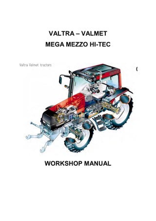
  • 1. VALTRA – VALMET MEGA MEZZO HI-TEC WORKSHOP MANUAL
  • 2. Service Manual Tractors Power transmission Brake system Steering sys- tem and Front axle Frame and Wheels Tools Cab and Shields Hydraulics Valtra Inc. 44200 Suolahti, Finland Groups 10---100 General Engine Electrical system 40 50 60 70 80 100 90 6000, 6100, 6200 6250, 6300, 6350 6400, 6550, 6600 6650, 6800, 6850 6900, 8000, 8100 8200, 8400, 8050 8150, 8450, 8550 8750, 8950 6600E---8750E 10 20 30
  • 3. Order no 39 210 211 ENGLISH
  • 4. 10. General 11. Layout 12. Repairs 13. Maintenance
  • 5. 2
  • 6. 3 To the reader The Service Manual for the Valmet tractors is intended to be a practical reference source to be used in work- shop. The repair instructions in the manual are based on methods which have been worked out in practice during normal workshop conditions and which are based on the use of special tools from the manufacturer when stated in the instructions. The manual also contains descriptions of the design and function of the components. Detailed maintenance instructions can be found in Operator’s Manual. The Service Manual will be continually updated with new revised pages which should be inserted in the manual. Alterations and additions will first appear as service bulletins. Only genuine Valmet spare parts should be used to ensure the best possible function of the machine. Cer- tain operations should be carried out with the aid of special tools designed by Valmet. Valmet Tractors Inc. Tractor Service
  • 7. 4
  • 8. Model Code Page 11. General 6000--8950 110 01. 9. 2002 1. 8. 2000 The following supplements have been published for the Valmet 6000---8950 Service Manual: Ordering number Date Notes 39 256 211 39 256 212 39 256 213 39 256 214 39 256 215 39 256 216 39 256 217 39 256 218 39 256 219 39 260 211 39 260 212 39 260 213 39 260 214 39 260 215 15. 6. 1992 1. 9. 1992 15. 5. 1993 1. 1. 1994 1. 1. 1995 15. 4. 1995 15. 5. 1996 1. 4. 1997 1. 8. 1998 1. 11. 1998 1. 6. 1999 1. 10. 1999 1. 8. 2000 1. 9. 2002 Supplement no. 39 256 211 (15. 6. 1992) Includes: --- Autocontrol III --- air conditioning --- tractor 8000 --- amendments Supplement no. 39 256 212 (1. 9. 1992) Includes: --- 20---series engines --- amendments Supplement no. 39 256 213 (15. 5. 1993) Includes: --- Delta Powershift --- tractor 8400 --- amendments --- the latest fitting instructions of optional equipment Supplement no. 39 256 214 (1. 1. 1994) Includes: --- tractors 6000 and 8200 --- Autocontrol II --- Autocontrol IV --- Sige---axle differential lock --- industrial front axle --- latest air conditioning --- amendments Supplement no. 39 256 215 (1. 1. 1995) Includes: --- amendments --- the latest fitting instructions of optional equipment Supplement no. 39 256 216 (15. 4. 1995) Includes: --- engine intake air system and cooling system, modifications --- Autocontrol 2.1 --- Agrodata---instrument --- hydraulic type clutch release mechanism --- DPS, modifications Supplement no. 39 256 217 (15. 5. 1996) Includes: --- tractor 6800 --- tractors 8050---8750 --- amendments Supplement no. 39 256 218 (1. 4. 1997) Includes: --- tractors 6200 and 8000R --- front PTO --- CareTel --- Hi Shift --- amendments --- the latest fitting instructions of optional equipment Supplement no. 39 256 219 (1. 8. 1998) Includes: --- FieldMaster --- pressure air brakes for trailer (optional) --- latest fitting instructions for optional equipment --- amendments --- new folder, new index leaves (10---30 and40---100) andnew spine labels. Supplement no. 39 260 211 (1. 11. 1998) Includes: --- HiTech reverse shuttle --- Autocontrol V --- New 50---series models --- Front axle air suspension --- E---engines --- Amendments Supplement no. 39 260 212 (1. 6. 1999) Includes: --- Autocontrol 2.2 --- amendments (e.g. for AC V) --- fitting instructions for optional equipment Supplement no. 39 260 213 (1. 10. 1999) Includes: --- Carraro 20.29 front axle --- amendments (e.g. version 42 of AC V) Supplement no. 39 260 214 (1. 8. 2000) Includes: --- HiTech gen. 2, AC---5.2 --- front PTO on 6250H---6850Hi tractors --- modified lubricating oil pump for 6---cyl. engines --- new rear axle housing for transmissions 650/550 --- amendments --- updated fitting instructions for optional equipment Supplement no. 39 260 215 (1. 9. 2002) Includes: --- transmission and final drives 700 --- Agroline---instrument --- technical modifications
  • 9. 6
  • 10. 7 Model Code Page 11. Layout 8. 11. 1990 6000--8750 110 1 Layout of Service Manual 1. Division into groups The manual is divided intogroups (10---100) which are based on the make---up of the tractor. The groups are listed on the firstindex leaf. Example. 10. General 20. Engine, fuel and cooling systems 30. Electrical system 40. Power transmission a.s.o. The number designation for each group is given in the top left box of the respective pages (and the first figure in the code designa- tion) 410 1 50 60 70 80 90 100 Code Page 2. Division into components or sub---groups Each group is further divided into components or sub---groups. The number and the name of each component is given in the top left box on each page (and comprise the two first figures in the code designation). Example. 41. Clutch 42. Gearbox 44. Quick---shift gear 45. Final drives etc.
  • 11. 8 Model Code Page 11. Layout 8. 11. 1990 6000--8750 110 2 3. Code designation Three---digit code designations are used to distinguish the different document groups for the respective components. The same code is also used in the Time List as a reference tothe text in this Manual. The code designation numbers appear both in the box at the top of the page and also in the headings. Example: Code 410: --- Group: Power transmission (4) --- Component: Clutch (41) --- Document group: General (410) 4. Page numbers The instructions for all components are numbered in consecutive order in the right---hand box at the top of the page. The page numbers begin with page 1 for each component. 41. Clutch 15. 5. 1993 Model Code Page 6100---8400 410 1 8. 11. 1990 5. Date At the top of each page there are two boxes for dates. In the case of a revised issue, the date of the earlier issue is printed in the crossed---over box and the date of the current issue is printed in the ”real” date box. 6. Model At the top of each page the tractor model for which the page is valid is indicated. 7. Additions and amendments of the service manual New and up---dated pages will be continually added to the service manual. The new pages should be inserted as indicated by the code: the first digit (also the first digit on the index leaf) indicated the group: --- the two first digits indicate the component or sub---group --- the third digit indicates the document group for the respective components --- the page number indicates the definite position of the page within the service manual If there are two pages with the same code and page number the page with the later date in the date box (and the old date in the crossed---over box) is valid (or the current page). N.B. Fitting instructions for extra equipment are inserted into the service manual at the end of group concerned (E.g. code 39 is inserted at the end of group 30).
  • 12. 9 Model Code Page 11. Layout 6000--8750 110 31. 4. 1997 8. 11. 1990 Code designation in the Service Manual 10. General 110 Layout 120 Repairs 130 Maintenance 20 Engine 21. Engine 210 Technical data, tools, description 211 Cylinder block and flywheel housing 212 Cylinder head and valve mechanism 213 Crank mechanism 214 Timing gears 215 Lubrication system and oil sump 216 Induction and exhaust system, turbocharger 219 Removing and fitting engine 22. Fuel system 220 Technical data, tools, description 222 Fuel feed pump and fuel filters 223 Injection pump and injectors 23. Cooling system 230 Technical data, tools, description 231 Thermostat and coolant pump 30. Electrical system 310 Specifications, wiring diagrams 311 Autocontrol II 312 Autocontrol 2.1 313 Sigma---power 320 AC power lift 321 ACD power lift 330 Agrodata 331 AD---instrument 340 Autocontrol---III 350 Autocontrol IV 360 CareTel 40. Power transmission 41. Clutch 410 Technical data, tools, description 411 Clutch assembly and pedal rods 412 Hydraulic coupling 42. Gearbox 420 Technical data, tools, description 421 Selector forks 422 Gear shift levers 423 Shafts and gear wheels 424 Differential 44. Quick---shift gear, DPS, reverse shuttle, 4WD clutch 440A Quick---shift gear, technical data, tools, description 440B Reverse shuttle, technical data, tools, description 440C 4WD clutch, technical data, tools, description 441 Quick---shift gear, repair instructions 442 Reverse shuttle, repair instructions 443 4WD clutch, repair instructions 444 DPS, repair instructions 45. Final drives 450 Technical data, tools, description 451 Final drives, repair instructions 46 Power take---off 460 Technical data, tools, description 461 Power take---off, repair instructions 463 Front PTO, repair instructions
  • 13. 10 Model Code Page 11. Layout 6000--8750 110 41. 4. 1997 8. 11. 1990 50. Brakes 510 Technical data, description 511. Service brakes 520 Parking brake 60. Steering system and front axle 61. Steering system 610 Technical data, tools, description 611 Steering valve 612 Priority valve 613 Steering cylinder 614 Adjustment 64. Powered front axle 640 Technical data, tools, description 641 Front axle housing and front axle suspension 643 Hubs 644 Differential 645 Industrial front axle 70 Frame and wheels 710 Tractor frame 720 Tyres and wheel discs 80 Cab and shields 810 Cab 820 Shields 830 Air conditioner 90 Hydraulics 910 Technical data, tools, description 911 Pump and pipes 912 Working hydraulics 913 Three---point linkage, towing hook 920 AC power lift 100. Special tools 101 Special tools (ETV) 102 Locally manufactured tools Note! Separate fitting instructions for the optional equipments are inserted into the Service Manual. These instructions are posi- tioned to the end of each main group. E.g. code 39 are placed to the end of group 30.
  • 14. 11 Model Code Page 12. Repairs 8. 11. 1990 6000--8750 120 1 General instructions for repairs Outer oil seals The Service Manual contains instructions for changing all outer oil seals, (e.g. oil seals on the PTO shaft end, on the output shaft to the front wheel drive and on the pinion shaft on the powered front axle, and so on). Sealing compound and glue If sealing compounds or glue are required for the repair work, the instructions will specify a sealing compound or glue which is readily available through specialist dealers. Some seals should be greased before fitting and the space between the lips of the seal should be filled with universal grease. If the seal is to be pushed over splines or sharp edges the seal should be protected with for example a thin plastic foil. Tightening torques and setting values All necessary tightening torques and setting values for each repair operation are given at the beginning of each repair section under the heading Technical Data. The most important values can also be found in the repair instructions. Table 1 later gives the tightening torques in order of dimension, quality and surface treatment. The values given in the table should be used if the tightening torque is not given in the repair instructions. Safety Always bear safety in mind when repairing or servicing the tractor. Use tools and lifting devices in the correct way . When you are removing tractor components or splitting the tractor, every tractor part must be supported in such a way, that norisk of accident exists. Avoid working under the supported tractor part if it is not absolutely necessary. When supporting the tractor the centre of gravity of the frame part must always be checked. For instance the wedges must always be fitted between front axle and engine to prevent axle oscillation when splitting the front frame of the tractor. Trouble---shooting The following procedure, combined with the information contained in the workshop manual will be helpful in tracing faults accu- rately. It consists of following a number of logical steps to locate and correct the problem: a) Determine the problem b) List possible causes c) Differentiate the causes d) Conduct checks in logical order to determine the exact cause e) Consider approximate remaining service life against cost of parts and labour.. f) Make any necessary repairs. g) Recheck the parts and functions for correct operation
  • 15. 12 Model Code Page 12. Repairs 8. 11. 1990 6000--8750 120 2 Handling of heavy components Unless otherwise specified, all removals should be accom- plished using adjustable lifting equipment. All supporting slings must be parallel to each other and as near vertical as possible in relation to the object being lifted. However, where slings are of a far greater capacity than the weight of the load to be fitted, a triangular lifting arrangement may be used. Oikein Rätt Right Richtig Giusto Väärin Fel Wrong Falsch Sbagliato Correct Teisingai Mauvais Netei- singai When removing a component at an angle, remember that the capacity of an eyebolt is reduced when the angle between the supporting members and the object becomes less than 90˚. B C D A Forged eyebolt support A. Load B. Lifting shackle C. Shackle retaining plate ( 3 mm thick) D. Sleeve When necessary the forged eyebolt can be supported in the way shown in figure above. Sleeve D may or may not be welded to plate. Warning! If a part resists removal, check that allnuts andbolts have been removed and that there is no interference from ad- jacent parts. Cleanliness Toensure long life of a machine, it is important tokeep dirt and foreign material out of its vital working components. Precau- tions must be taken to safeguard against this. Enclosed com- partments, seals and filters have been provided to keep the supply of air, fuel and lubricant clean. These protective de- vices must not be removed. Whenever hydraulic, fuel, lubricating oil or lines are discon- nected, clean the point of disconnection and the surrounding area. As soon as a line has been disconnected, cap, plug or tape the line or opening to prevent the ingress of foreign ma- terial. The same cleaning and covering precautions should be taken when access covers or inspection plates are removed. Clean and inspect all parts. Make sure that all passages and holes are clear. Cover all parts to keep them clean. Make sure parts are clean when they are reassembled. Leave new parts in their wrapping until they are actuallyneeded forreassembly Assembly When reassembling a machine, complete each step in se- quence. never partially assemble one part then start to as- semble another. Make all recommended adjustments. Al- ways check the job on completion to ensure that nothing has been overlooked. Recheck the various adjustments before putting the machine back into service. Note! Before fitting new parts, remove rust preventative com- pound from all machined surfaces (usually ”peel---off sub- stances). Lubrication Where applicable, fill the compartments of repaired or re- newed components with the quantity, type and grade of clean lubricant recommended in the routine maintenance section of the Operator’s Manual. Shims When shims are removed, tie them together and identify their location. Keep shims clean and take care not to bend them before refitting them. Gaskets Make sure that the holes in gaskets line up with lubricating oil passages in the mating parts. If gaskets have tobe made, use material of the correct type and thickness. Make sure that holes are punched in the right places. Incorrectly punched gaskets can cause serious damage. Lip type rubber seals Lubricate the lips of lip---type rubber seals with oil before fit- ment. Do not use grease on seals, except for grease seals.
  • 16. 13 Model Code Page 12. Repairs 8. 11. 1990 6000--8750 120 3 4 5 3 2 1 The main parts of lip---type seal: 1. Case 2. Sealing element 3. Ring spring The figure above shows the construction of a simple lip---type seal. The cross section shows the heel (4) and the toe (5), used to identify the sides of a single element seal. With a few exceptions, the toe of a single---lip is located on the lubricant side. Some seals have a second auxiliary lip which has no spring. Cables and wires When removing or disconnecting a group of cables or wires, label each one to ensure correct refitment. Locking devices Correct and incorrect use of retainers Correct and incorrect method of fitting and bending locking tabs. Slackening of nuts and bolts is prevented by mechanical means such as lockwashers, tab washers and cotter pins, or by Loctite---type locking agents. Flat retainers must be installed properly to be effective. Bend one end of the retainer against the edge of the part. Bend the other end against one of the nut or bolt head.Always fit new retainers in compartments which house moving parts. When fitting lockwashers on aluminium housings, place a flat washer between the lockwasher and the housing. Note! 1) Never fit a lockwasher (Grower, fan, spring, etc.)under anut or bolt to which a specified torque has to be applied. 2) Always thoroughly degrease components before applying Loctite type locking agents. Bushes and press fits Do not fit bushes with a hammer alone. Use a suitable fitting tool and a hammer or, better still, a press if possible.. When using a press, ensure that pressure is applied directly in line with the bore. If the ring has an oil hole, take care toalign it with the oil hole in the mating part. When press fitting a part into another part, lubricate the mating surfaces. Tapered parts should be assembled dry. Before assembly, check that the tapers are dry and free from burrs. Fitting bolts in blind holes Use bolts of the correct length. A bolt which is too long may ”bottom” before the head comes into contact with the part it is to hold: this will cause damage to the threads. If a bolt is too short, there may not be enough threads engaged to hold the part securely.
  • 17. 14 Model Code Page 12. Repairs 8. 11. 1990 6000--8750 120 4 Table Table 1. Tightening torques, metric standard thread (ISO) Tightening torques Nm1) Dim. Quality, surface treatment, material and so on 8.8 lubr. tol.± 8.8 Zne2) tol± 8.8 Znk3) tol. ± 10.9 lubr. tol. ± 12.9 lubr tol. ± M4 --- --- --- --- --- M5 6,4 0,6 5,7 0,5 --- 9 1 11 1 M6 11 1 10 1 12 1,2 15 1,5 18 2 M8 25 2 23 2 30 3 35 4 45 5 M10 50 5 45 5 60 5 70 7 90 10 M12 90 10 80 8 100 10 125 10 151 15 M14 140 15 125 10 160 15 200 20 240 20 M16 220 20 195 20 250 25 300 30 370 40 M18 300 30 270 30 350 35 430 40 510 50 M20 430 40 380 40 480 50 600 60 720 70 M22 570 60 500 50 650 65 800 80 970 100 M24 740 70 660 70 830 80 1030 100 1250 120 M27 1100 100 950 100 1200 120 1500 150 1800 180 M30 1500 150 1300 130 1600 160 2040 200 2500 250 1) 1 Nm=0,102 kpm 2) Zne=zinc electroplating 3) Znk=hot galvanized If the bolts differs from the standard range the values in the table must not be used.
  • 18. 15 Model Code Page 12. Repairs 8. 11. 1990 6000--8750 120 5 Conversion table for common units Quantities and units Conversion factors Overall and detail dimensions millimetres (mm) 100 mm=3,94 inches 1 inch=25,4 mm Short distances e.g. turning circles metres (m) 1 m=3,28 ft 1 ft=0,305 m Travel distances kilometres 1 km=0,62 mile 1 mile=1,61 km Tractor weights, axle loadings kilograms (kg) 1 kg=2,2 lbs 1 lb=0,454 kg Travel speed kilometres per h (km/h) 1 km/h=0,62 mph 1 mph=1,61 km/h Drawbar pull kilonewtons (kN) 1 kN=224,8 lbs 1 lb=4,448 N Power (identified by such terms as crankshaft power, 1 kW=1,34 hp pto power, belt power, drawbar power, indicating 1 hp=0,746 kW the point at which the measurement was taken) kilowatts (kW) Engine torque newton metres (Nm) 1 Nm=0,74 ft lb 1 ft lb=1,356 Nm Fuel consumption by weight (kilograms per hr, kg/h) 1 kg/h=2,2 lb/hr (by volume) litres per hr (l/h) 1 lb=0,454 kg 1 l/h=0,22 gal/hr 1 gal=4,54 l Fuel economy (specific fuel consumption) 304 g/kWh=0,5 lb/hp hr grams per kilowatt hr (g/kWh) Engine displacement litres (l) 1 l=61,02 m cu in 100 cu in=1,639 l Hydraulic pump 1 MPa=145 psi pressure---mecapascal (MPa) 1000 psi=6,9 MPa delivery---millimetres per sec (ml/s) 100 ml/s=1,32 gpm 1 gpm=75,77 ml/s Tyre pressure---kilopascal (kPa) 100 kPa=14,5 psi 1 psi=6,9 kPa Area acres---hectare To convert multiply by 0,404686 Volume bushel---litre To convert multiply by 39,3687 Quantity pound per acre---kilogram per hectare Multiply by 1,12085 Volume Multiply by superficial foot---cubic metre 0,002360
  • 19. 16
  • 20. 17 Model Code Page 13. Maintenance 15. 5. 1996 6000--8750 130 1 1. 1. 1994 Maintenance Valmet 6000---8750 N.B. Detailed maintenance instructions, see Operator’s Man- ual. General Correct maintenance at the right time is a basic condition for reliable operation of the tractor. Maintenance costs are small compared with any repair costs resulting from lack of main- tenance. The most important measures are those which you carry out yourself and which include lubrication and various checks and adjustments. The service intervals shown apply for normal operating condi- tions but in more severe conditions servicing should be car- ried out more frequently. General instructions concerning oil checks and oil filling --- Always stop the engine before starting work --- Apply the parking brake to ensure the tractor cannot move. If the ground is uneven the wheels should be scotched --- Wash down the tractor first so that the work can be done more easily and quickly. --- Always observe the utmost cleanliness in all mainten- ance work. Thoroughly wipe off filler caps and plugs as well as surrounding parts of the tractor before filling up with fuel or oil. --- Inspect the oil and filters when changing. Large amounts of dirt (e.g. heavily clogged filters) can point to a fault which could cause extensive and costly repairs if not corrected in time. ---When carrying out checks the tractor should stand on level ground. --- Levels should be checked in the morning when the oil is cold and has had time torun down tothe bottom of the unit concerned. --- When changing the oil, bear in mind that the oil can be very hot when it drains from the tractor. Waste oil and oil filters should be handled carefully and disposed of properly --- After completion of the service work always replace all safety covers etc. Greasing lubricating points fitted with grease nipples --- Always clean the grease nipples before applying the grease gun. --- Apply grease through the nipples until clean grease oozes out (unless otherwise instructed). --- Wipe away superfluous grease which has been pressed out at the lubricating point. --- Preferably carry out lubrication with bearing points and joints unloaded and with the bearings in different positions. Lubrication and maintenance schedule All intervals are counted from zerohours on the hour recorder. For example, 1000 hours service is carried out every 1000 (yearly), 2000 hours (every other year) etc. even if the guaran- tee service has been carried out. Example: The 1000 hour service contains all itemsmentioned under 10 h/Daily, 50 h/once a week, 250 h, 500 h and 1000 h.
  • 21. 18 Model Code Page 13. Maintenance 1. 4. 1997 6000--8750 130 2 15. 5. 1996 Maintenance schedule 4 5 614 14 15 15 6084---67 6 6 6 1 14 2 4 5 6 7 8 910 11 12 1415 16 17 18 Daily/every 10 hours 1. Check engine oil level 2. Check coolant level and radiator fins 3. Check for leakage Weekly/every 50 hours 4. Grease three---point linkage and towing hook 5. Grease brake mechanism (EP grease) 6. Grease front axle brackets (also nipples on steering system and on non---powered front axle) 7. Check oil level in transmission and hydraulics 8. Clean air filter cyclone (tractors with a horizontally fitted air filter and an ejector pipe; clean suction housing hole plate) 9. Check fan belt tightness 10.Check water trap (on 6---cylinder engines. On other mo- dels on the other side. On models 8200, 8400 and 8050---8750 also under both fuel filters) 11.Check electrolyte level in battery Every 250 hours 12. Clean engine air filter 13. Grease door and window hinges and locks 14. Change engine oil and filter 15. Grease front axle joints (powered axle) 16. Change pressure filters. First change at 100 hours war- ranty service, then at 250 hours and after that at 500 hours and then at intervals of 500 running hours. 17. Check brake fluid level (and clutch fluid level, 668103---) 18. Clean cab ventilation air filter 19. Check wheel nuts and bolts and tyre pressures
  • 22. 19 Model Code Page 13. Maintenance 1. 11. 1998 6000--8750 130 3 1. 4. 1997 6084---68 27 30 25 34 22 27 29 31 36 28 33 26 24 39 35 36 32 30 25 38 21 23 37 20 41 33 24 26 42 40 43 33 32 25 Every 500 hours 20. Clean water trap (fuel system) (on 6---cylinder engines. On the other models on the other side. On models 8200, 8400 and 8050---8750 also under the fuel filters). Does not concern 6200 and 8000R tractors. 21. Check brake pedal free travel 22. Check clutch pedal free travel, ---668102. 23. Change pressure filters (transmission and hydraulics) 24. Check oil level in front axle differential and hubs 24a. Calibrate first time gaspedal on HiTech models. Later at intervals of 1000 running hours. Every 1000 hours/yearly 25. Change oil in transmission/hydraulics and clean suc- tion strainer 26. Change oil in front axle differential and hubs 27. Change cab ventilation air filter and wash cab recircula- tion filter, if fitted. 28. Change fuel filters. 6200, 8000R: change also the water trap filter 29. Change safety filter (in engine air filter) 30. Grease rear drive axle bearings 31. Grease flywheel ring gear 32. Check, grease and adjust front wheel bearings on non---powered front axle 33. Check/adjust front wheel toe---in 34. Clean fuel tank 35. Adjust valves 35a Calibrate gas pedal on HiTech models Every 2000 hours/every other year 36. Change engine coolant 37. Change brake fluid (and clutch fluid, 668103---) 38. Change transmission housing breather 39. Check and clean injectors 40. Check alternator 41. Check starter motor Every 4000 hours 42. Check function of turbocharger at authorized workshop (if fitted) 43. Change engine rubber vibration damber on 6---cyl. engines (not 8200 and 8450---8750)
  • 23. 4 Model Code Page 13. Maintenance 6000--8950 130 41. 9. 2002 1. 8. 2000 Recommended fuel and lubricants (all capacities are incl. of filters) Part of machine SAE---grade API---grade Capacity (litres) Engine: --- 6100 (3---cyl.) 15W40 +40˚C 10˚C CG 4 10 --- 6000, 6200---6650Hi, 6800---6850Hi (4---cyl.) 15W40 +40˚C...---10˚C 10W/30 +30˚C...---20˚C CG---4 CH---4 13 -- 6900, 8000, 8100, 8200, 8400, 8050--8950Hi (6--cyl.) 10W/30 +30 C...---20 C CH---4 19 Hydraulics/transmission HT 60: ---30˚C...+30˚C HT 100: ---10˚C...+40˚C GL---4 (G2---98) 34 (43 max/HiTech, 8050---, J02316---: 45 max) (extra max 50/HiTech, 8050---, J02316---: extra max 53). 6200---8950 *): min 45, max 55, extra max 65. 8950Hi **): min 45, max 55, extra max. 65. Powered front axle: --- differential, Dana / ind. Carraro 8 / 6 --- hubs, Dana 80W/90 GL---5 (LS) 2x1 --- hubs, ind. front axle Dana+Carraro 2x1,5 Fuel tank: --- 6000---8000 Hi Trol, 6250Hi---6650Hi HiTrol 158 --- other models diesel fuel 165 --- extra fuel reservoir, metallic / plastic +82 / +121 Cooling system:Cooling system: --- 6100 (with larger radiator) 13,5 (17,5) --- 6000, 6200---6600 (with openable front grille) 15,5 (17) --- 6250 Hi---6650 Hi 17 --- 6800 / 6850 Hi water+anti---freeze agent (standardi ASTM 22 / 22 --- 8000---8400 (with openable front grille) water+anti---freeze agent (standardi ASTM D3306---86a tai BS 6580:1985) 24 (25) --- 8200, 8400, 8050, 8150 with expansion tank ) 28 (8400, model 2001: 30) --- 8050 Hi and 8150 Hi 28 --- 8450, 8550 / 8450 Hi, 8550 Hi 25 / 27 --- 8750 / 8950Hi 31 / 31 Brake fluid reservoir/Clutch fluid resesvoir brake fluid SAE J1703 0,3 / 0,2 Window washer reservoir washer fluid 3 Oils in front PTO units see page 463/9. *) Tractor frame numbers, see page 450/6. **) Tractor frame numbers, see page 450/8. Oil quality and capacity in fluid couplings (Hi---Trol) Voith TD---VA coupling used up to serial no 658205 and Voith TD---FVA1 from serial no 666066. Engine oil SAE 10W/30 year around or automatic transmission fluid ATF which meets standards: GM type A Suffix A, GM Dexron II (e.g. Neste ATF---X): ---658205 666066--- --- 6000, 6100 --- 7,20 litres --- 6200, 6300 7,4 litres 6200: 7,35 litres. 6300: 7,45 litres. 6250Hi: 7,40 litres. 6350Hi: 7,80 litres. --- 6400 7,6 litres 7,85 litres. 6550Hi: 7,90 litres. --- 6600 7,8 litres 7,90 litres. 6650Hi: 8,00 liter --- 6800, 8000R, 8000 6800: 8,40 litres. 6900, 8000: 8,00 litres. 6850Hi: 8,00 litres. Transfluid---coupling with effect from tractor serial no 658206 up to tractor serial no 666065. Engine oil SAE 10W/30 year around or automatic transmission fluid ATF which meets standards: GM type A Suffix A, GM Dexron II (e.g. Neste ATF---X): 658206--- 659409---666065 659408 *) --- 6100 5,2 l 6,4 l --- 6300 5,4 l 6,6 l --- 6400 5,6 l 6,8 l --- 6600, 8000 5,8 l 7,0 l *) Check the manufacturing date of the coupling. If it is 1292 or later, use larger filling quantities.
  • 24. 20. Engine 21. Engine 22. Fuel system 23. Cooling system 21
  • 25. 22
  • 26. 23 Model Code Page 21. Engine 1. 9. 1992 6000--8750 210 1 15. 6. 1992 Contents General (Op. no. 210): Specifications 3. . . . . . . . . . . . . . . . . . . . . . . . . . . . . . . . . . . . . . . . . . . . . . . . . . . . . . . . . . . . . . . . . . . Special tools 10. . . . . . . . . . . . . . . . . . . . . . . . . . . . . . . . . . . . . . . . . . . . . . . . . . . . . . . . . . . . . . . . . . . . Engine, description 12. . . . . . . . . . . . . . . . . . . . . . . . . . . . . . . . . . . . . . . . . . . . . . . . . . . . . . . . . . . . . . Repair instructions Cylinder block and flywheel housing (Op. no. 211): 1. Cylinder block and cylinder liners: A. Measuring cylinder liner wear 1. . . . . . . . . . . . . . . . . . . . . . . . . . . . . . . . . . . . . . . . . . . . . . . . . . . B. Removing cylinder liners 1. . . . . . . . . . . . . . . . . . . . . . . . . . . . . . . . . . . . . . . . . . . . . . . . . . . . . . . . C. Checking cylinder block 1. . . . . . . . . . . . . . . . . . . . . . . . . . . . . . . . . . . . . . . . . . . . . . . . . . . . . . . . D. Changing camshaft bushing 1. . . . . . . . . . . . . . . . . . . . . . . . . . . . . . . . . . . . . . . . . . . . . . . . . . . . E. Oversize bushings for camshaft 2. . . . . . . . . . . . . . . . . . . . . . . . . . . . . . . . . . . . . . . . . . . . . . . . . F. Fitting plug at rear end of camshaft 3. . . . . . . . . . . . . . . . . . . . . . . . . . . . . . . . . . . . . . . . . . . . . . . G. Fitting pipe for oil dipstick 4. . . . . . . . . . . . . . . . . . . . . . . . . . . . . . . . . . . . . . . . . . . . . . . . . . . . . . H. Fitting cylinder liners 4. . . . . . . . . . . . . . . . . . . . . . . . . . . . . . . . . . . . . . . . . . . . . . . . . . . . . . . . . . . 2. Flywheel housing: A. Fitting flywheel housing 6. . . . . . . . . . . . . . . . . . . . . . . . . . . . . . . . . . . . . . . . . . . . . . . . . . . . . . . . B. Changing crankshaft rear oil seal 6. . . . . . . . . . . . . . . . . . . . . . . . . . . . . . . . . . . . . . . . . . . . . . . . C. Changing flywheel starter gear 7. . . . . . . . . . . . . . . . . . . . . . . . . . . . . . . . . . . . . . . . . . . . . . . . . . D. Fitting flywheel 7. . . . . . . . . . . . . . . . . . . . . . . . . . . . . . . . . . . . . . . . . . . . . . . . . . . . . . . . . . . . . . . . Cylinder head and valve mechanism (Op. no. 212): 1. Cylinder head: A. Removing cylinder head 1. . . . . . . . . . . . . . . . . . . . . . . . . . . . . . . . . . . . . . . . . . . . . . . . . . . . . . . . B. Removing valves 1. . . . . . . . . . . . . . . . . . . . . . . . . . . . . . . . . . . . . . . . . . . . . . . . . . . . . . . . . . . . . . C. Checking cylinder head 1. . . . . . . . . . . . . . . . . . . . . . . . . . . . . . . . . . . . . . . . . . . . . . . . . . . . . . . . D. Changing valve guides 2. . . . . . . . . . . . . . . . . . . . . . . . . . . . . . . . . . . . . . . . . . . . . . . . . . . . . . . . . E. Machining valve seat 2. . . . . . . . . . . . . . . . . . . . . . . . . . . . . . . . . . . . . . . . . . . . . . . . . . . . . . . . . . . F. Changing valve seat inserts 3. . . . . . . . . . . . . . . . . . . . . . . . . . . . . . . . . . . . . . . . . . . . . . . . . . . . . G. Grinding valves 3. . . . . . . . . . . . . . . . . . . . . . . . . . . . . . . . . . . . . . . . . . . . . . . . . . . . . . . . . . . . . . . H. Fitting valves 3. . . . . . . . . . . . . . . . . . . . . . . . . . . . . . . . . . . . . . . . . . . . . . . . . . . . . . . . . . . . . . . . . I. Fitting cylinder head 4. . . . . . . . . . . . . . . . . . . . . . . . . . . . . . . . . . . . . . . . . . . . . . . . . . . . . . . . . . . . 2.Valve mechanism: A. Reconditioning rocker arm mechanism 5. . . . . . . . . . . . . . . . . . . . . . . . . . . . . . . . . . . . . . . . . . . B. Changing camshaft/camshaft gear 5. . . . . . . . . . . . . . . . . . . . . . . . . . . . . . . . . . . . . . . . . . . . . . . C. Adjusting valve clearance 6. . . . . . . . . . . . . . . . . . . . . . . . . . . . . . . . . . . . . . . . . . . . . . . . . . . . . . . Crank mechanism (Op. no. 213): 1. Crankshaft: A. Removing crankshaft 1. . . . . . . . . . . . . . . . . . . . . . . . . . . . . . . . . . . . . . . . . . . . . . . . . . . . . . . . . . B. Checking crankshaft 1. . . . . . . . . . . . . . . . . . . . . . . . . . . . . . . . . . . . . . . . . . . . . . . . . . . . . . . . . . . C. Changing crankshaft gears 1. . . . . . . . . . . . . . . . . . . . . . . . . . . . . . . . . . . . . . . . . . . . . . . . . . . . . D. Changing crankshaft ring gear (420---engines) 2. . . . . . . . . . . . . . . . . . . . . . . . . . . . . . . . . . . . . E. Fitting crankshaft 2. . . . . . . . . . . . . . . . . . . . . . . . . . . . . . . . . . . . . . . . . . . . . . . . . . . . . . . . . . . . . . 2. Connecting rods and pistons: A. Removing piston together with connecting rod 3. . . . . . . . . . . . . . . . . . . . . . . . . . . . . . . . . . . . . B. Changing connecting rod bearings 3. . . . . . . . . . . . . . . . . . . . . . . . . . . . . . . . . . . . . . . . . . . . . . . C. Checking connecting rod 3. . . . . . . . . . . . . . . . . . . . . . . . . . . . . . . . . . . . . . . . . . . . . . . . . . . . . . .
  • 27. 24 Model Code Page 21. Engine 1. 9. 1992 6000--8750 210 2 15. 6. 1992 D. Connecting rods, weight classes 4. . . . . . . . . . . . . . . . . . . . . . . . . . . . . . . . . . . . . . . . . . . . . . . . . E. Changing piston rings 5. . . . . . . . . . . . . . . . . . . . . . . . . . . . . . . . . . . . . . . . . . . . . . . . . . . . . . . . . . F. Checking piston 6. . . . . . . . . . . . . . . . . . . . . . . . . . . . . . . . . . . . . . . . . . . . . . . . . . . . . . . . . . . . . . . G. Fitting piston pin 6. . . . . . . . . . . . . . . . . . . . . . . . . . . . . . . . . . . . . . . . . . . . . . . . . . . . . . . . . . . . . . H. Fitting piston together with connecting rod 6. . . . . . . . . . . . . . . . . . . . . . . . . . . . . . . . . . . . . . . . 3. Balancer unit, 420---engines: A. Removing and dismantling balancer unit 7. . . . . . . . . . . . . . . . . . . . . . . . . . . . . . . . . . . . . . . . . . B. Reconditioning balancer unit 7. . . . . . . . . . . . . . . . . . . . . . . . . . . . . . . . . . . . . . . . . . . . . . . . . . . . C. Fitting balancer unit 8. . . . . . . . . . . . . . . . . . . . . . . . . . . . . . . . . . . . . . . . . . . . . . . . . . . . . . . . . . . . Engine timing gears (Op. no. 214) A. Removing timing gear casing 1. . . . . . . . . . . . . . . . . . . . . . . . . . . . . . . . . . . . . . . . . . . . . . . . . . . B. Reconditioning idler gear 1. . . . . . . . . . . . . . . . . . . . . . . . . . . . . . . . . . . . . . . . . . . . . . . . . . . . . . . C. Fitting timing gear casing 2. . . . . . . . . . . . . . . . . . . . . . . . . . . . . . . . . . . . . . . . . . . . . . . . . . . . . . . Lubrication system and oil sump (Op. no. 215): A. Reconditioning oil relief valve for lubrication oil pressure 1. . . . . . . . . . . . . . . . . . . . . . . . . . . . . B. Removing and dismantling lubricating oil pump 1. . . . . . . . . . . . . . . . . . . . . . . . . . . . . . . . . . . . C. Assembling and fitting lubricating oil pump 2. . . . . . . . . . . . . . . . . . . . . . . . . . . . . . . . . . . . . . . D. Fitting oil sump gasket 2. . . . . . . . . . . . . . . . . . . . . . . . . . . . . . . . . . . . . . . . . . . . . . . . . . . . . . . . . E. Lubricating oil quality requirements 3. . . . . . . . . . . . . . . . . . . . . . . . . . . . . . . . . . . . . . . . . . . . . . Inlet and exhaust system, turbocharger (Op. no. 216): A. Checking air filter 1. . . . . . . . . . . . . . . . . . . . . . . . . . . . . . . . . . . . . . . . . . . . . . . . . . . . . . . . . . . . . . B. Checking inlet and exhaust system 1. . . . . . . . . . . . . . . . . . . . . . . . . . . . . . . . . . . . . . . . . . . . . . . C. Checking turbocharger 1. . . . . . . . . . . . . . . . . . . . . . . . . . . . . . . . . . . . . . . . . . . . . . . . . . . . . . . . . D. Reconditioning turbocharger 3. . . . . . . . . . . . . . . . . . . . . . . . . . . . . . . . . . . . . . . . . . . . . . . . . . . . E. Fitting turbocharger 5. . . . . . . . . . . . . . . . . . . . . . . . . . . . . . . . . . . . . . . . . . . . . . . . . . . . . . . . . . . . Working orders (Op. no. 219) 1. . . . . . . . . . . . . . . . . . . . . . . . . . . . . . . . . . . . . . . . . . . . . . . .
  • 28. 5 1. 9. 2002 6000--6800 210 3 1. 8. 2000 Model Code Page 21. Engine Specifications Engine designations 1. Basic markings: 320, 420, 620 and 634. The first digit indicates the number of cylinders and the two last digits the stroke (---20=120 mm, ---34=134 mm). 2. Letters after the basic markings: --- D=diesel engine --- S=turbocharger (Schwitzer) --- W=by--pass turbocharger, Delta turbo (Schwitzer S1BG or S2BG) --- B=Bosch P in---line pump --- R=distributor pump (Stanadyne) --- I=intercooler --- E=low emission engines (E---engines) --- C=emission tested engines (certificated). Note! R24, E77 and EPA---homologations has been made for E---engines. Tractor 6000 6100 6200 6200 6250 Hi 6300 6300 (---K41123) (K41124---) (K41309--- ---L23437) Designation 420D 320 DS 420DSRE 420DSRE 420DSRE 420 DS 420DS Turbocharger no yes yes yes yes yes yes No of cylinders 4 3 4 4 4 4 4 Displacement (litres) 4,4 3,3 4,4 4,4 4,4 4,4 4,4 Cyl. bore (mm) 108 108 108 108 108 108 108 Stroke (mm) 120 120 120 120 120 120 120 Compr. ratio 16,5:1 16,5:1 16,5:1 16,5:1 16,5:1 16,5:1 16,5:1 Output (kW/r/min DIN) 55/2300 58/2300 59/2225 59/2200 59/2200 62,5/2225 66/2200 Torque (Nm/r/min DIN) 290/1450 310/1550 320/1400 360/1400 360/1400 330/1550 360/1400 Moment rise % 27 28,5 27 41 41 23 25 Low idling (r/min) 750 800 750 750 850 750 750 Compr. press 1) (bar) 24 24 24 24 24 24 24 Max. no--load revs (r/min) 2500 2500 2425 2400 2400 2425 2400 Tractor 6300 6350 Hi 6400 6400 6400 6400 (L23438---) (J17109---) (K41106---) (L23506---) (Delta) (Delta) Designation 420DSRE 420DSRE 420 DS 420 DW 420DW 420DWRE Turbocharger yes yes yes yes yes yes No of cylinders 4 4 4 4 4 4 Displacement (litres) 4,4 4,4 4,4 4,4 4,4 4,4 Cyl. bore (mm) 108 108 108 108 108 108 Stroke (mm) 120 120 120 120 120 120 Compr. ratio 16,5:1 16,5:1 16,5:1 16,5:1 16,5:1 16,5:1 Output (kW/r/min DIN) 66/2200 66/2200 70/2225 70/2225 73,5/2200 73,5/2200 Torque (Nm/r/min DIN) 400/1400 400/1400 365/1550 390/1550 415/1400 430/1400 Moment rise % 39 39 22 31 30 35 Low idling (r/min) 750 850 750 750 750 750 Compr. press 1) (bar) 24 24 24 24 24 24 Max. no--load revs (r/min) 2400 2400 2425 2425 2400 2400 Tractor 6550 Hi 6600 6600E 6650 Hi 6750Hi*) 6800 6800E Designation 420DWRE 420 DS 420 DS 420DWRE 420DWRIE 420 DWI 420DWI Turbocharger yes yes yes yes yes (+interc..) yes (+interc..) yes (+interc..) No of cylinders 4 4 4 4 4 4 4 Displacement (litres) 4,4 4,4 4,4 4,4 4.4 4,4 4,4 Cyl. bore (mm) 108 108 108 108 108 108 108 Stroke (mm) 120 120 120 120 120 120 120 Compr. ratio 16,5:1 16,5:1 16,5:1 16,5:1 16,5:1 16,5:1 16,5:1 Output (kW/r/min DIN) 73,5/2200 77/2225 77/2225 81/2200 77/1800 85/2225 85/2225 Torque (Nm/r/min DIN) 430/1400 405/1550 405/1550 460/1400 530/1150 440/1550 440/1550 Moment rise % 35 22 22 31 29 21 21 Low idling (r/min) 850 850 850 850 800 850 850 Compr. press 1) (bar) 24 24 24 24 24 24 24 Max. no--load revs (r/min) 2400 2425 2425 2400 2000 2425 2425 1) Minimum value at operating temperature and starting revs. Max permitted difference between cylinders 3,0 bar. *) Low revs engine. E = AC---4, Control system for tractor. Hi = HiTech.
  • 29. 6 1. 9. 2002 6800--8400 210 3A 1. 8. 2000 Model Code Page 21. Engine Specifications Tractor 6800 6850 Hi 6900 8000 8050 8050 (L23517---) (---L23317) (L23318---) Designation 420 DWRIE 420 DWRIE 620 DRE 620 D 620 DSR 620DSRE Turbocharger yes (+interc..) yes (+interc..) no no yes yes No of cylinders 4 4 6 6 6 6 Displacement (litres) 4,4 4,4 6,6 6,6 6,6 6,6 Cyl. bore (mm) 108 108 108 108 108 108 Stroke (mm) 120 120 120 120 120 120 Compr. ratio 16,5:1 16,5:1 16,5:1 16,5:1 16,5:1 16,5:1 Output (kW/r/min DIN) 88/2200 88/2200 75/2225 73,5/2225 81/2200 81/2200 Torque (Nm/r/min DIN) 490/1400 490/1400 390/1400 380/1550 490/1300 490/1400 Moment rise % 28 28 21 20 39 21 Low idling (r/min) 850 850 750 750 750 850 Compr. press 1) (bar) 24 24 24 24 24 24 Max. no--load revs (r/min) 2400 2400 2425 2425 2400 2425 Tractor 8050 Hi 8100 8100E 8150 8150E 8150 8150 Hi (---L24138) (L24139---) Designation 620DSRE 620 D 620 D 620 DSR 620 DSR 620DSRE 620DSRE Turbocharger yes no no yes yes yes yes No of cylinders 6 6 6 6 6 6 6 Displacement (litres) 6,6 6,6 6,6 6,6 6,6 6,6 6,6 Cyl. bore (mm) 108 108 108 108 108 108 108 Stroke (mm) 120 120 120 120 120 120 120 Compr. ratio 16,5:1 16,5:1 16,5:1 16,5:1 16,5:1 16,5:1 16,5:1 Output (kW/r/min DIN) 81/2200 88/2225 88/2225 92/2200 92/2200 92/2200 92/2200 Torque (Nm/r/min DIN) 490/1400 455/1550 455/1550 540/1300 540/1300 540/1400 540/1400 Moment rise % 39 21 21 35 35 35 35 Low idling (r/min) 750 750 750 750 750 750 750 Compr. press 1) (bar) 24 24 24 24 24 24 24 Max. no--load revs (r/min) 2400 2425 2425 2400 2400 2400 2400 Tractor 8200 8200E 8350Hi*) 8400 8400E 8400 8400 (---K34331) (K32135--- (L23130---) ---L33320) Designation 634 D 634 D 620DSRIE 620 DS 620 DS 620 DS 620 DSIE Turbocharger no no yes (+interc..) yes yes yes yes (+interc..) No of cylinders 6 6 6 6 6 6 6 Displacement (litres) 7,4 7,4 6,6 6,6 6,6 6,6 6,6 Cyl. bore (mm) 108 108 108 108 108 108 108 Stroke (mm) 134 134 120 120 120 120 120 Compr. ratio 16,5:1 16,5:1 16,5:1 16,5:1 16,5:1 16,5:1 16,5:1 Output (kW/r/min DIN) 95,5/2225 95,5/2225 99/1800 103/2200 103/2200 110/2200 118/2200 Torque (Nm/r/min DIN) 490/1550 490/1550 650/1100 520/1550 520/1550 625/1400 650/1400 Moment rise % 20 20 23 16 16 30 27 Low idling (r/min) 750 750 800 750 750 750 750 Compr. press 1) (bar) 24 24 24 24 24 24 24 Max. no--load revs (r/min) 2425 2425 2000 2400 2400 2400 2400 1) Minimum value at operating temperature and starting revs. Max permitted difference between cylinders 3,0 bar. *) Low revs engine. E = AC---4, Control system for tractor. Hi = HiTech.
  • 30. 7 1. 9. 2002 8450--8950 210 3B 1. 8. 2000 Model Code Page 21. Engine Specifications Tractor 8450 8450E 8450 8450 Hi 8550 8550E 8550 (---L24134) (L24135---) (---L24115) (L24116---) Designation 620 DWR 620 DWR 620 DWRE 620DWRE 634 DSR 634 DSR 634DSRE Turbocharger yes yes yes yes yes yes yes No of cylinders 6 6 6 6 6 6 6 Displacement (litres) 6,6 6,6 6,6 6,6 7,4 7,4 7,4 Cyl. bore (mm) 108 108 108 108 108 108 108 Stroke (mm) 120 120 120 120 134 134 134 Compr. ratio 16,5:1 16,5:1 16,5:1 16,5:1 16,5:1 16,5:1 16,5:1 Output (kW/r/min DIN) 103/2200 103/2200 103/2200 103/2200 118/2200 118/2200 118/2200 Torque (Nm/r/min DIN) 580/1450 580/1450 615/1400 615/1400 650/1450 650/1450 650/1400 Moment rise % 30 30 38 38 27 27 27 Low idling (r/min) 750 750 750 750 750 750 750 Compr. press 1) (bar) 24 24 24 24 24 24 24 Max. no--load revs (r/min) 2400 2400 2400 2400 2400 2400 2400 Tractor 8550 Hi 8750 8750E 8950 Hi (---J32215) Designation 634DSRE 634 DS 634 DS 634 DSBIE Turbocharger yes yes yes yes (+interc..) No of cylinders 6 6 6 6 Displacement (litres) 7,4 7,4 7,4 7,4 Cyl. bore (mm) 108 108 108 108 Stroke (mm) 134 134 134 134 Compr. ratio 16,5:1 16,5:1 16,5:1 16,5:1 Output (kW/r/min DIN) 118/2200 118/140/2200 118/140/2200 118/147/2200 Torque (Nm/r/min DIN) 650/1400 650/1450 650/1450 650/820/1400 Moment rise % 27 27 27 27/28 Low idling (r/min) 750 750 750 750 Compr. press 1) (bar) 24 24 24 24 Max. no--load revs (r/min) 2400 2400 2400 2400 1) Minimum value at operating temperature and starting revs. Max permitted difference between cylinders 3,0 bar. E = AC---4, Control system for tractor. Hi = HiTech. Valves, rockers and tappets With a valve clearance of 1,0 mm: --- inlet valve opens 0˚±2˚ B.T.D.C. . . . . . . . . . . . . . . . . . . . . . . . . . . . . . . . . . . . . . . . . . . . . . . . . . . . . . . . . . . . . . . --- inlet valve closes 16˚±2˚ A.B.D.C. . . . . . . . . . . . . . . . . . . . . . . . . . . . . . . . . . . . . . . . . . . . . . . . . . . . . . . . . . . . . . --- exhaust valve opens 39˚±2˚ B.B.D.C. . . . . . . . . . . . . . . . . . . . . . . . . . . . . . . . . . . . . . . . . . . . . . . . . . . . . . . . . . . --- exhaust valve closes 1˚±2˚ A.T.D.C. . . . . . . . . . . . . . . . . . . . . . . . . . . . . . . . . . . . . . . . . . . . . . . . . . . . . . . . . . . Valve clearance cold and hot: --- inlet valve 0,35 mm. . . . . . . . . . . . . . . . . . . . . . . . . . . . . . . . . . . . . . . . . . . . . . . . . . . . . . . . . . . . . . . . . . . . --- exhaust valve 0,35 mm. . . . . . . . . . . . . . . . . . . . . . . . . . . . . . . . . . . . . . . . . . . . . . . . . . . . . . . . . . . . . . . . . Angle of valve seat in cylinder head: --- inlet valve 35˚+20’. . . . . . . . . . . . . . . . . . . . . . . . . . . . . . . . . . . . . . . . . . . . . . . . . . . . . . . . . . . . . . . . . . . . --- exhaust valve 45˚+20’. . . . . . . . . . . . . . . . . . . . . . . . . . . . . . . . . . . . . . . . . . . . . . . . . . . . . . . . . . . . . . . . . Width of valve seat in cylinder head: --- inlet valve 2,9...3,7 mm. . . . . . . . . . . . . . . . . . . . . . . . . . . . . . . . . . . . . . . . . . . . . . . . . . . . . . . . . . . . . . . . . . . . --- exhaust valve 1,3...2,3 mm. . . . . . . . . . . . . . . . . . . . . . . . . . . . . . . . . . . . . . . . . . . . . . . . . . . . . . . . . . . . . . . . . Angle of valve face: --- inlet valve 35˚---20’. . . . . . . . . . . . . . . . . . . . . . . . . . . . . . . . . . . . . . . . . . . . . . . . . . . . . . . . . . . . . . . . . . . . --- exhaust valve 45˚---20’. . . . . . . . . . . . . . . . . . . . . . . . . . . . . . . . . . . . . . . . . . . . . . . . . . . . . . . . . . . . . . . . . Outside diameter of valve head: --- inlet valve 48 mm. . . . . . . . . . . . . . . . . . . . . . . . . . . . . . . . . . . . . . . . . . . . . . . . . . . . . . . . . . . . . . . . . . . . --- exhaust valve 41 mm. . . . . . . . . . . . . . . . . . . . . . . . . . . . . . . . . . . . . . . . . . . . . . . . . . . . . . . . . . . . . . . . . Max valve movement: --- inlet valve 10,9 mm. . . . . . . . . . . . . . . . . . . . . . . . . . . . . . . . . . . . . . . . . . . . . . . . . . . . . . . . . . . . . . . . . . . . --- exhaust valve 12,1 mm. . . . . . . . . . . . . . . . . . . . . . . . . . . . . . . . . . . . . . . . . . . . . . . . . . . . . . . . . . . . . . . . . Inlet valve stem diameter 8,960...8,975 mm. . . . . . . . . . . . . . . . . . . . . . . . . . . . . . . . . . . . . . . . . . . . . . . . . . . . . . . . . . Exhaust valve stem diameter 8,925...8,940 mm. . . . . . . . . . . . . . . . . . . . . . . . . . . . . . . . . . . . . . . . . . . . . . . . . . . . . . Inlet valve stem clearance 0,025...0,055 mm. . . . . . . . . . . . . . . . . . . . . . . . . . . . . . . . . . . . . . . . . . . . . . . . . . . . . . . . . --- Reject limit 0,30 mm. . . . . . . . . . . . . . . . . . . . . . . . . . . . . . . . . . . . . . . . . . . . . . . . . . . . . . . . . . . . . . . . . . . Exhaust valve stem clearance 0,060...0,090 mm. . . . . . . . . . . . . . . . . . . . . . . . . . . . . . . . . . . . . . . . . . . . . . . . . . . . . . --- Reject limit 0,35 mm. . . . . . . . . . . . . . . . . . . . . . . . . . . . . . . . . . . . . . . . . . . . . . . . . . . . . . . . . . . . . . . . . . .
  • 31. 26 Model Code Page 21. Engine 1. 8. 1998 6000--8750 210 4 1. 1. 1994 Inside diameter of valve guide before fitting 9,000...9,015 mm. . . . . . . . . . . . . . . . . . . . . . . . . . . . . . . . . . . . . . . . . . Outside diameter of valve guide 16,028...16,039 mm. . . . . . . . . . . . . . . . . . . . . . . . . . . . . . . . . . . . . . . . . . . . . . . . . . . . Diameter of valve guide bore in cylinder head 16,000...16,018 mm. . . . . . . . . . . . . . . . . . . . . . . . . . . . . . . . . . . . . . . . Protrusion of valve guide top above cylinder head surface 21 mm. . . . . . . . . . . . . . . . . . . . . . . . . . . . . . Depth of valve face below cylinder head surface: --- inlet valve 0,7±0,05 mm. . . . . . . . . . . . . . . . . . . . . . . . . . . . . . . . . . . . . . . . . . . . . . . . . . . . . . . . . . . . . . . . . . . . --- exhaust valve 0,6±0,05 mm. . . . . . . . . . . . . . . . . . . . . . . . . . . . . . . . . . . . . . . . . . . . . . . . . . . . . . . . . . . . . . . . . Valve spring free length 69,8 mm. . . . . . . . . . . . . . . . . . . . . . . . . . . . . . . . . . . . . . . . . . . . . . . . . . . . . . . . . . . Spring pressure when spring compressed to a length of: --- 48,6 mm 327±17 N. . . . . . . . . . . . . . . . . . . . . . . . . . . . . . . . . . . . . . . . . . . . . . . . . . . . . . . . . . . . . . . . . . . . . --- 37,4 mm 500±23 N. . . . . . . . . . . . . . . . . . . . . . . . . . . . . . . . . . . . . . . . . . . . . . . . . . . . . . . . . . . . . . . . . . . . . Rocker arm shaft diameter 19,959...19,980. . . . . . . . . . . . . . . . . . . . . . . . . . . . . . . . . . . . . . . . . . . . . . . . . . . . . . . . Inside diameter of rocker arm bearing bush: --- (when fitted in position) 19,990...20,010 mm. . . . . . . . . . . . . . . . . . . . . . . . . . . . . . . . . . . . . . . . . . . . . . . . . . . . . . . . . Outside diameter of rocker arm bearing bush 23,035...23,075 mm. . . . . . . . . . . . . . . . . . . . . . . . . . . . . . . . . . . . . . . . Diameter of rocker arm bore 23,000...23,021 mm. . . . . . . . . . . . . . . . . . . . . . . . . . . . . . . . . . . . . . . . . . . . . . . . . . . . . . . Max. permissible push rod deflection (when free) 0,4 mm. . . . . . . . . . . . . . . . . . . . . . . . . . . . . . . . . . . . . Free length of rocker arm spring 80 mm. . . . . . . . . . . . . . . . . . . . . . . . . . . . . . . . . . . . . . . . . . . . . . . . . . . Spring pressure when spring compressed to a length 58 mm 80...100 N. . . . . . . . . . . . . . . . . . . . . . . . . . . Outside diameter of tappet 29,939...29,960 mm. . . . . . . . . . . . . . . . . . . . . . . . . . . . . . . . . . . . . . . . . . . . . . . . . . . . . . . . Diameter of tappet bore in cylinder block 30,000...30,043 mm. . . . . . . . . . . . . . . . . . . . . . . . . . . . . . . . . . . . . . . . . . . . Engines from week 34 1996: Rocker arm shaft diameter 22,970...22,990 mm. . . . . . . . . . . . . . . . . . . . . . . . . . . . . . . . . . . . . . . . . . . . . . . . . . . . . . . . Diameter of rocker arm bore 23,000...23,021 mm. . . . . . . . . . . . . . . . . . . . . . . . . . . . . . . . . . . . . . . . . . . . . . . . . . . . . . . Camshaft Diameter of camshaft bearing journal no 1 49,925...49,950 mm. . . . . . . . . . . . . . . . . . . . . . . . . . . . . . . . . . . . . . . . . . . Diameter of camshaft bearing journals (others that no 1) 49,885...49,910 mm. . . . . . . . . . . . . . . . . . . . . . . . . . . . . . . Diameter of camshaft bearing journals nos 2, 3 and 4 (620/634---engines) 49,865...49,890 mm. . . . . . . . . . . . . . . . Inside diameter of camshaft bearing bushes (when fitted in position) 50,010...50,070 mm. . . . . . . . . . . . . . . . . . . . . Diameter of camshaft bearing bores (others than no 1) 50,000...50,025 mm. . . . . . . . . . . . . . . . . . . . . . . . . . . . . . . . Camshaft clearance in bearing bush no 1 0,060...0,145 mm. . . . . . . . . . . . . . . . . . . . . . . . . . . . . . . . . . . . . . . . . . . . Camshaft clearance in bearing bushes (others than no 1) 0,090...0,140 mm. . . . . . . . . . . . . . . . . . . . . . . . . . . . . . Camshaft clearance in bearing bushes nos 2, 3 and 4 (620/634---engines) 0,110...0,160 mm. . . . . . . . . . . . . . . . Bearing bush tolerance in block (press fit) 0,025...0,080 mm. . . . . . . . . . . . . . . . . . . . . . . . . . . . . . . . . . . . . . . . . . . Diameter of bearing bush bore in block 55,620...55,650 mm Camshaft end play with 0,5 mm gasket between cylinder block and timing gear housing and between timing gear housing and front cover 0,5...1,0 mm. . . . . . . . . . . . . . . . . . . . . . . . . . . . . Cam height (distance between back of cam and tip of cam): --- inlet valve 41,180...41,430 mm. . . . . . . . . . . . . . . . . . . . . . --- exhaust valve 40,080...40,330 mm. . . . . . . . . . . . . . . . . . . Cam lift: --- inlet valve 7,38 mm. . . . . . . . . . . . . . . . . . . . . . --- exhaust valve 8,28 mm. . . . . . . . . . . . . . . . . . . Camshaft max permissible deflection (total indicator reading) 0,03 mm. . . . . . . . . . . . . . . . . . . . . . . . . . . Cylinder liners Protrusion of cylinder liner above cylinder block top face 0,030...0,080 mm. . . . . . . . . . . . . . . . . . . . . . . . . . . . . . . Max. permissible height difference between liners (under same head) 0,02 mm. . . . . . . . . . . . . . . . . . . . Outer diameter of cylinder liner guide: --- at upper end of liner 124,475...124,500 mm. . . . . . . . . . . . . . --- at lower end of liner 122,961...122,986 mm. . . . . . . . . . . . . . Liner bore 108,000...108,022 mm. . . . . . . . . . . . . . . . . . . . . . . . Height of cylinder liner flange 9,03...9,05 mm. . . . . . . . Height of cylinder liner flange, 1st oversize, part no 8366 47933 9,08...9,10 mm. . . . . . . . . . . . . . . . . . . . . . . . . Height of cylinder liner flange, 2nd oversize, part no 8366 47934 9,13...9,15 mm. . . . . . . . . . . . . . . . . . . . . . . . Height of cylinder liner flange, 3rd oversize, part no 8366 47935 9,23...9,25 mm. . . . . . . . . . . . . . . . . . . . . . . . . Outer diameter of cylinder liner flange 131,700...131,800 mm. Piston, rings and gudgeon pin Minimum distance between piston and cylinder head (measured with a piece of lead wire thought the injector location hole) 0,900...1,150 mm. . . . . . . . . . . . . . . . . . . . . . . . . . . . . . . . . . . . . . . . Piston diameter: --- 17 mm from lower edge (320, 420, 620---engines) 107,873...107,887 mm. . . . . . . . . . . . . . . . . . . . . . . . . . . . . . . . . . --- 19 mm from lower edge (634---engines) 107,883...107,897 mm. . . . . . . . . . . . . . . . . . . . . . . . . . . . . . . . . . . . . . . . . . .
  • 32. 27 Model Code Page 21. Engine 1. 4. 1997 6000--8750 210 5 15. 5. 1996 Pin bore in piston 40,003...40,009 mm. . . . . . . . . . . . . . . . . . . . . . . . . . . . . . . . . . . . . . . . . . . . . . . . . . . . . . . . . . . . . . . . Piston pin diameter 39,991...40,000 mm. . . . . . . . . . . . . . . . . . . . . . . . . . . . . . . . . . . . . . . . . . . . . . . . . . . . . . . . . . . . . . Width of ring grooves: --- 1st groove (right---angled ring; 6000, 6200, 6300, 8000R, 8000, 8100, 8050, 8150) 2,560...2,580 mm. . . . . . . --- 2nd grove 2,520...2,540 mm. . . . . . . . . . . . . . . . . . . . . . . . . . . . . . . . . . . . . . . . . . . . . . . . . . . . . . . . . . . . . . . . . . . . --- 3rd groove 4,040...4,060 mm. . . . . . . . . . . . . . . . . . . . . . . . . . . . . . . . . . . . . . . . . . . . . . . . . . . . . . . . . . . . . . . . . . . . Side clearance of piston rings in their grooves: --- 1st ring (right---angled ring; 6000, 6200, 6300, 8000R, 8000, 8100, 8050, 8150) 0,07...0,102 mm. . . . . . . . . . --- 2nd ring 0,03...0,062 mm. . . . . . . . . . . . . . . . . . . . . . . . . . . . . . . . . . . . . . . . . . . . . . . . . . . . . . . . . . . . . . . . . . . . . . --- 3rd ring 0,05...0,082 mm. . . . . . . . . . . . . . . . . . . . . . . . . . . . . . . . . . . . . . . . . . . . . . . . . . . . . . . . . . . . . . . . . . . . . . --- reject limit 0,15 mm. . . . . . . . . . . . . . . . . . . . . . . . . . . . . . . . . . . . . . . . . . . . . . . . . . . . . . . . . . . . . . . . . . . . Piston ring height (in direction of cylinder): --- 1st ring (right---angled ring; 6000, 6200, 6300, 8000R, 8000, 8100, 8050, 8150) 2,478...2,490 mm. . . . . . . . . . --- 2nd ring 2,478...2,490 mm. . . . . . . . . . . . . . . . . . . . . . . . . . . . . . . . . . . . . . . . . . . . . . . . . . . . . . . . . . . . . . . . . . . . . . --- 3rd ring 3,975...3,990 mm. . . . . . . . . . . . . . . . . . . . . . . . . . . . . . . . . . . . . . . . . . . . . . . . . . . . . . . . . . . . . . . . . . . . . . Piston ring gap (with piston fitted in cylinder) --- 1st ring (wedge shaped ring; 6100, 6400, 6600, 6800, 8200, 8400, 8450, 8550, 8750) 0,40...0,55 mm. . . . . --- 1st ring (right---angled ring; 6000, 6200, 6300, 8000R, 8000, 8100, 8050, 8150) 0,30...0,45 mm. . . . . . . . . . --- 2nd ring 0,60...0,80 mm. . . . . . . . . . . . . . . . . . . . . . . . . . . . . . . . . . . . . . . . . . . . . . . . . . . . . . . . . . . . . . . . . . . . . . --- 3rd ring 0,30...0,60. . . . . . . . . . . . . . . . . . . . . . . . . . . . . . . . . . . . . . . . . . . . . . . . . . . . . . . . . . . . . . . . . . . . . . --- reject limit 1,0 mm. . . . . . . . . . . . . . . . . . . . . . . . . . . . . . . . . . . . . . . . . . . . . . . . . . . . . . . . . . . . . . . . . . . . Max. permissible weight difference between pistons in same engine 25 g. . . . . . . . . . . . . . . . . . . . . Piston to be heated up to 100˚C before fitting gudgeon pin. Piston position in cylinder: combustion chamber of piston to face towards injector. Connecting rod Inside diameter of piston pin bush (with bush pressed into connecting rod) 40,025...40,040 mm. . . . . . . . . . . . . . . Outside diameter of piston pin bush 44,082...44,120 mm. . . . . . . . . . . . . . . . . . . . . . . . . . . . . . . . . . . . . . . . . . . . . . . . Interference fit: connecting rod small end bushing---connecting rod 0,057...0,120 mm. . . . . . . . . . . . . . . . . . . . . . Connecting rod small end bore 44,000...44,025. . . . . . . . . . . . . . . . . . . . . . . . . . . . . . . . . . . . . . . . . . . . . . . . . . . . Connecting rod big end bore 71,730...71,749 mm. . . . . . . . . . . . . . . . . . . . . . . . . . . . . . . . . . . . . . . . . . . . . . . . . . . . . . Big end bearing shell thickness: --- standard 1,835...1,842 mm. . . . . . . . . . . . . . . . . . . . . . . . . . . . . . . . . . . . . . . . . . . . . . . . . . . . . . . . . . . . . . . . . . . . . --- 1st undersize 0,25 mm 1,960...1,967 mm. . . . . . . . . . . . . . . . . . . . . . . . . . . . . . . . . . . . . . . . . . . . . . . . . . . . . . . . . --- 2nd undersize 0,50 mm 2,085...2,092 mm. . . . . . . . . . . . . . . . . . . . . . . . . . . . . . . . . . . . . . . . . . . . . . . . . . . . . . . . . --- 3rd undersize 1,00 mm 2,335...2,342 mm. . . . . . . . . . . . . . . . . . . . . . . . . . . . . . . . . . . . . . . . . . . . . . . . . . . . . . . . . --- 4th undersize 1,50 mm 2,585...2,592 mm. . . . . . . . . . . . . . . . . . . . . . . . . . . . . . . . . . . . . . . . . . . . . . . . . . . . . . . . . Big---end bearing clearance 0,046...0,098 mm. . . . . . . . . . . . . . . . . . . . . . . . . . . . . . . . . . . . . . . . . . . . . . . . . . . . . . . End float (side clearance) at big---end on crankshaft 0,200...0,410 mm. . . . . . . . . . . . . . . . . . . . . . . . . . . . . . . . . . . Piston pin bushing location perpendicular to longitudinal axis of connecting rod to be within 0,15:100. . . . . . . . . . . . . . . . . . . . . . . . . . . . . . . . . . . . . . . . . . . . . . . . . . . . . . . . . . . . . . . . . . Piston pin bushing location and big---end bearing location to be parallel to within 0,05:100. . . . . . . . . . Weight marking (letter) at lower end. Max. permissible weight difference between connecting rods in the same engine 20 g. . . . . . . . . . Position of connecting rod; order no at valve mechanism side (away from the combustion chamber in the piston) Crankshaft Crankpin diameter: --- standard 67,981...68,000 mm. . . . . . . . . . . . . . . . . . . . . . . . . . . . . . . . . . . . . . . . . . . . . . . . . . . . . . . . . . . . . . . . . . . . . --- 1. undersize 0,25 mm 67,731...67,750 mm. . . . . . . . . . . . . . . . . . . . . . . . . . . . . . . . . . . . . . . . . . . . . . . . . . . . . . . . . . --- 2. undersize 0,50 mm 67,481...67,500 mm. . . . . . . . . . . . . . . . . . . . . . . . . . . . . . . . . . . . . . . . . . . . . . . . . . . . . . . . . .
  • 33. 28 Model Code Page 21. Engine 1. 9. 1992 6000--8750 210 6 8. 11. 1990 --- 3. undersize 1,00 mm 66,981...67,000 mm. . . . . . . . . . . . . . . . . . . . . . . . . . . . . . . . . . . . . . . . . . . . . . . . . . . . . . . . . . --- 4. undersize 1,50 mm 66,481...66,500 mm. . . . . . . . . . . . . . . . . . . . . . . . . . . . . . . . . . . . . . . . . . . . . . . . . . . . . . . . . . Crankpin length 40,000...40,160 mm. . . . . . . . . . . . . . . . . . . . . . . . . . . . . . . . . . . . . . . . . . . . . . . . . . . . . . . . . . . . . . . . . Main bearing journal diameter: --- standard 84,985...85,020 mm. . . . . . . . . . . . . . . . . . . . . . . . . . . . . . . . . . . . . . . . . . . . . . . . . . . . . . . . . . . . . . . . . . . . . --- 1st undersize 0,25 mm 84,735...84,770 mm. . . . . . . . . . . . . . . . . . . . . . . . . . . . . . . . . . . . . . . . . . . . . . . . . . . . . . . . . --- 2nd undersize 0,50mm 84,485...84,520 mm. . . . . . . . . . . . . . . . . . . . . . . . . . . . . . . . . . . . . . . . . . . . . . . . . . . . . . . . . --- 3rd undersize 1,00 mm 83,985...84,020 mm. . . . . . . . . . . . . . . . . . . . . . . . . . . . . . . . . . . . . . . . . . . . . . . . . . . . . . . . . --- 4th undersize 1,50 mm 83,485...83,520 mm. . . . . . . . . . . . . . . . . . . . . . . . . . . . . . . . . . . . . . . . . . . . . . . . . . . . . . . . . Main bearing location diameter (in cylinder block) 91,000...91,025 mm. . . . . . . . . . . . . . . . . . . . . . . . . . . . . . . . . . . . . Main bearing shell thickness: --- standard 2,955...2,965 mm. . . . . . . . . . . . . . . . . . . . . . . . . . . . . . . . . . . . . . . . . . . . . . . . . . . . . . . . . . . . . . . . . . . . . --- 1st undersize 0,25 mm 3,080...3,090 mm. . . . . . . . . . . . . . . . . . . . . . . . . . . . . . . . . . . . . . . . . . . . . . . . . . . . . . . . . --- 2nd undersize 0,50 mm 3,205...3,215 mm. . . . . . . . . . . . . . . . . . . . . . . . . . . . . . . . . . . . . . . . . . . . . . . . . . . . . . . . . --- 3rd undersize 1,00 mm 3,455...3,465 mm. . . . . . . . . . . . . . . . . . . . . . . . . . . . . . . . . . . . . . . . . . . . . . . . . . . . . . . . . --- 4th undersize 1,50 mm 3,705...3,715 mm. . . . . . . . . . . . . . . . . . . . . . . . . . . . . . . . . . . . . . . . . . . . . . . . . . . . . . . . . Main bearing clearance 0,050...0,127 mm. . . . . . . . . . . . . . . . . . . . . . . . . . . . . . . . . . . . . . . . . . . . . . . . . . . . . . . . . . . Length of thrust bearing journal (journal nearest to flywheel): --- standard (2 standard thrust plates) 45,000...45,080 mm. . . . . . . . . . . . . . . . . . . . . . . . . . . . . . . . . . . . . . . . . . . . . . . --- 1st oversize (one std and one 0,1 mm overthick thrust plate) 45,100...45,180 mm. . . . . . . . . . . . . . . . . . . . . . . . . --- 2nd oversize (one std and one 0,2 mm overthick thrust plate) 45,200...45,280 mm. . . . . . . . . . . . . . . . . . . . . . . . . --- 3rd oversize (one 0,1 mm and one 0,2 mm overthick thrust plate) 45,300...45,380 mm. . . . . . . . . . . . . . . . . . . . . --- 4th oversize (two 0,2 mm overthick thrust plates) 45,400...45,480 mm. . . . . . . . . . . . . . . . . . . . . . . . . . . . . . . . . . . Other crankshaft journals may not be ground longer. Crankshaft end float 0,100...0,380 mm. . . . . . . . . . . . . . . . . . . . . . . . . . . . . . . . . . . . . . . . . . . . . . . . . . . . . . . . . . . . . . Max. permissible ovality and other deformity of crankpins or journals 0,03 mm. . . . . . . . . . . . . . . . . . . . Crankshaft unbalance 1,0 Ncm Max.. . . . . . . . . . . . . . . . . . . . . . . . . . . . . . . . . . . . . . . . . . . . . . . . . . . . . . . . . . . . Balancing unit ring gear location, diameter (420 engines) 150,220...150,260 mm. . . . . . . . . . . . . . . . . . . . . . . . . . . . . . Balancing unit ring gear I.D. (420 engines) 150,000...150,040 mm. . . . . . . . . . . . . . . . . . . . . . . . . . . . . . . . . . . . . . . . . . . Flywheel Flywheel ring gear no. of teeth 133 pcs. . . . . . . . . . . . . . . . . . . . . . . . . . . . . . . . . . . . . . . . . . . . . . . . . . . . . Interference fit between ring gear---flywheel 0,425...0,600 mm. . . . . . . . . . . . . . . . . . . . . . . . . . . . . . . . . . . . . . . . . . Before fitting the ring gear, heat up to a temperature of 150...200˚C. . . . . . . . . . . . . . . . . . . . . . . . . . . . . . . . Flywheel unbalance 1,0 Ncm Max. . . . . . . . . . . . . . . . . . . . . . . . . . . . . . . . . . . . . . . . . . . . . . . . . . . . . . . . . . . . . . Max permissible axial wobble of flywheel clutch face, measured at inner edge of clutch face on diameter 200 0,06:ø200. . . . . . . . . . . . . . . . . . . . . . . . . . . . . . . . . . . . . . . . . . . . . . . . . . . . . Timing gears Tooth backlash: Crankshaft---idler gear 0,05...0,25 mm. . . . . . . . . . . . . . . . . . . . . . . . . . . . . . . . . . . . . . . . . . . . . . . . . . . . . . . . . . . . Idler gear---camshaft gear 0,05...0,25 mm. . . . . . . . . . . . . . . . . . . . . . . . . . . . . . . . . . . . . . . . . . . . . . . . . . . . . . . . . Idler gear---fuel injection pump gear 0,05...0,25 mm. . . . . . . . . . . . . . . . . . . . . . . . . . . . . . . . . . . . . . . . . . . . . . . . Max. permissible side wobble of gears 0,05 mm. . . . . . . . . . . . . . . . . . . . . . . . . . . . . . . . . . . . . . . . . . . . . . Idler gear shaft, diameter 54,951...54,970 mm. . . . . . . . . . . . . . . . . . . . . . . . . . . . . . . . . . . . . . . . . . . . . . . . . . . . . . . . . . Inner diameter of idler gear bushing (fitted) 55,000...55,030 mm. . . . . . . . . . . . . . . . . . . . . . . . . . . . . . . . . . . . . . . . . . Inner diameter of Idler gear hole 60,000...60,030 mm. . . . . . . . . . . . . . . . . . . . . . . . . . . . . . . . . . . . . . . . . . . . . . . . . . . Camshaft gear hole diameter 32,000...32,025 mm. . . . . . . . . . . . . . . . . . . . . . . . . . . . . . . . . . . . . . . . . . . . . . . . . . . . . . Camshaft end diameter 32,043...32,059 mm. . . . . . . . . . . . . . . . . . . . . . . . . . . . . . . . . . . . . . . . . . . . . . . . . . . . . . . . . . .
  • 34. 29 Model Code Page 21. Engine 6000--8750 210 7 1. 8. 1998 1. 1. 1994 Timing marks: Timing marks on gears are in alignment when the 1st cylinder piston is at its top dead centre between compression and power strokes. On crankshaft gear 2 dots on tooth. . . . . . . . . . . . . . . . . . . . . . . . . . . . . . . . . . . . . . . . . . . . . . . . . . . . . . . . . . . . . . . On idler gear: --- against crankshaft gear mark 0 on tooth. . . . . . . . . . . . . . . . . . . . . . . . . . . . . . . . . . . . . . . . . . . . . . . . . . . . --- against camshaft gear mark 1 dot on tooth. . . . . . . . . . . . . . . . . . . . . . . . . . . . . . . . . . . . . . . . . . . . . . . . . . . . . --- against fuel injection pump gear mark 1 dot on notch. . . . . . . . . . . . . . . . . . . . . . . . . . . . . . . . . . . . . . . . . . . . On camshaft gear 1 dot on notch. . . . . . . . . . . . . . . . . . . . . . . . . . . . . . . . . . . . . . . . . . . . . . . . . . . . . . . . . . . . . . . . On injection pump gear 1 dot on tooth. . . . . . . . . . . . . . . . . . . . . . . . . . . . . . . . . . . . . . . . . . . . . . . . . . . . . . . . . . . Cylinder block Holes for guide pins 13,250...13,320 mm. . . . . . . . . . . . . . . . . . . . . . . . . . . . . . . . . . . . . . . . . . . . . . . . . . . . . . . . . . . . . . Main bearing location diameter 91,000...91,025 mm. . . . . . . . . . . . . . . . . . . . . . . . . . . . . . . . . . . . . . . . . . . . . . . . . . . . Main bearing location (with bearings 8361 40950) 92,000...92,025 mm. . . . . . . . . . . . . . . . . . . . . . . . . . . . . . . . . . . . . Cylinder liner location, diameter: --- upper end 124,514...124,554 mm. . . . . . . . . . . . . . . . . . . . . . . . . . . . . . . . . . . . . . . . . . . . . . . . . . . . . . . . . . . . . . . . . . . . --- lower end 123,000...123,040 mm. . . . . . . . . . . . . . . . . . . . . . . . . . . . . . . . . . . . . . . . . . . . . . . . . . . . . . . . . . . . . . . . . . . . Inner diameter of camshaft bushing (fitted) 50,010...50,070 mm. . . . . . . . . . . . . . . . . . . . . . . . . . . . . . . . . . . . . . . . . . Cylinder block height 428,170...428,430 mm. . . . . . . . . . . . . . . . . . . . . . . . . . . . . . . . . . . . . . . . . . . . . . . . . . . . . . . . . . . . . Distance between piston and top dead centre at different crank shaft angles Grad 320, 420, 620 mm 634 mm Grad 320, 420, 620 mm 634 mm 6˚ 10˚ 11˚ 12˚ 13˚ 14˚ 15˚ 16˚ 17˚ 18˚ 19˚ 20˚ 0,423 1,173 1,418 1,686 1,976 2,289 2,625 2,983 3,363 3,765 4,188 4,633 0,485 1,344 1,624 1,931 2,264 2,623 3,007 3,417 3,852 4,312 4,797 5,307 21˚ 22˚ 23˚ 24˚ 25˚ 26˚ 27˚ 28˚ 29˚ 30˚ 5,100 5,587 6,095 6,624 7,173 7,742 8,331 8,939 9,567 10,213 5,841 6,399 6,980 7,585 8,214 8,865 9,539 10,235 10,952 11,692 Cylinder head Height of cylinder head 104,800...105,000 mm. . . . . . . . . . . . . . . . . . . . . . . . . . . . . . . . . . . . . . . . . . . . . . . . . . . . . . . . . . . Height (min.) of cylinder head after repair grinding 104,000 mm. . . . . . . . . . . . . . . . . . . . . . . . . . . . . . . . . . . . Cylinder head straigthness: --- in lateral direction 0,05 mm. . . . . . . . . . . . . . . . . . . . . . . . . . . . . . . . . . . . . . . . . . . . . . . . . . . . . . . . . . . . . . --- in longitudinal direction 0,10 mm. . . . . . . . . . . . . . . . . . . . . . . . . . . . . . . . . . . . . . . . . . . . . . . . . . . . . . . . . Valve guide inner diameter (not fitted) 9,000---9,015 mm. . . . . . . . . . . . . . . . . . . . . . . . . . . . . . . . . . . . . . . . . . . . . . . Valve guide outer diameter 16,028...16,039 mm. . . . . . . . . . . . . . . . . . . . . . . . . . . . . . . . . . . . . . . . . . . . . . . . . . . . . . . . Valve guide bore diameter in cylinder head 16,000...16,018 mm. . . . . . . . . . . . . . . . . . . . . . . . . . . . . . . . . . . . . . . . . . Height of valve guide upper end from cylinder head surface 21 mm. . . . . . . . . . . . . . . . . . . . . . . . . . . . Valve head depth from cylinder head surface: --- inlet valve 0,7±0,05 mm (max. 1,70 mm). . . . . . . . . . . . . . . . . . . . . . . . . . . . . . . . . . . . . . . . . . . . . . . . . . . . . . . . . . . . . . . . . . . . --- exhaust valve 0,6±0,05 mm (max. 1,60 mm). . . . . . . . . . . . . . . . . . . . . . . . . . . . . . . . . . . . . . . . . . . . . . . . . . . . . . . . . . . . . . . . . Valve sealing surface angles: --- inlet valve 35˚+20’. . . . . . . . . . . . . . . . . . . . . . . . . . . . . . . . . . . . . . . . . . . . . . . . . . . . . . . . . . . . . . . . . . . . --- exhaust valve 45˚+20’. . . . . . . . . . . . . . . . . . . . . . . . . . . . . . . . . . . . . . . . . . . . . . . . . . . . . . . . . . . . . . . . . Valve sealing surface width: --- inlet valve 2,9...3,7 mm. . . . . . . . . . . . . . . . . . . . . . . . . . . . . . . . . . . . . . . . . . . . . . . . . . . . . . . . . . . . . . . . . . . . --- exhaust valve 1,3...2,3 mm. . . . . . . . . . . . . . . . . . . . . . . . . . . . . . . . . . . . . . . . . . . . . . . . . . . . . . . . . . . . . . . . . Diameter of exhaust valve seat insert 44,070...44,132 mm. . . . . . . . . . . . . . . . . . . . . . . . . . . . . . . . . . . . . . . . . . . . . . . . Diameter of exhaust valve seat insert location 44,000...44,025 mm. . . . . . . . . . . . . . . . . . . . . . . . . . . . . . . . . . . . . . . . Diameter of exhaust valve seat insert (repair part 8366 52269) 44,270...44,332 mm. . . . . . . . . . . . . . . . . . . . . . . . . . Diameter of exhaust valve seat insert location (repair part 8366 52269) 44,200...44,225 mm. . . . . . . . . . . . . . . . . . . Diameter of inlet valve seat insert (8366 47936) 48,570...48,632 mm. . . . . . . . . . . . . . . . . . . . . . . . . . . . . . . . . . . . . . . Diameter of inlet valve seat insert location 48,500...48,525 mm. . . . . . . . . . . . . . . . . . . . . . . . . . . . . . . . . . . . . . . . . . . . Diameter of inlet valve seat insert (repair part 8368 55347) 48,770...48,832 mm. . . . . . . . . . . . . . . . . . . . . . . . . . . . . Diameter of inlet valve seat insert location (repair part 8368 55347) 48,700...48,725 mm. . . . . . . . . . . . . . . . . . . . . .
  • 35. 30 Model Code Page 21. Engine 1. 1. 1994 6000--8750 210 8 1. 9. 1992 Lubricating system Oil pressure at normal running temperature: --- at idling speed (min.) 100 kPa (1,0 kp/cm2). . . . . . . . . . . . . . . . . . . . . . . . . . . . . . . . . . . . . . . . . . . . . . . . . . . . . . . . . . . --- at running speed 250---400 kPa (2,5---4,0 kp/cm2). . . . . . . . . . . . . . . . . . . . . . . . . . . . . . . . . . . . . . . . . . . . . . . . . . . . . . . . . . . . . . Free length of oil pressure valve spring 80 mm. . . . . . . . . . . . . . . . . . . . . . . . . . . . . . . . . . . . . . . . . . . . . . Spring pressure when valve spring is compressed to a length of 52 mm 54+5 N (5,4+0,5 kp). . . . . . . . . . . . . . . . . . Diameter of oil pressure valve plunger 19,602...19,635 mm. . . . . . . . . . . . . . . . . . . . . . . . . . . . . . . . . . . . . . . . . . . . . . Diameter of oil pressure valve cylinder 19,700...19,752 mm. . . . . . . . . . . . . . . . . . . . . . . . . . . . . . . . . . . . . . . . . . . . . . Oil filter by---pass valve opens at a pressure difference of 2±0,5 kp/cm2. . . . . . . . . . . . . . . . . . . . . . . . . . . . . . Oil pump (320, 420 engines) Backlash between gears when crankshaft lies firmly against the lower side of main bearings: --- crankshaft gear---lubricating oil pump gear 0,05...0,25 mm. . . . . . . . . . . . . . . . . . . . . . . . . . . . . . . . . . . . . . . . --- between the pump gears 0,16...0,26 mm. . . . . . . . . . . . . . . . . . . . . . . . . . . . . . . . . . . . . . . . . . . . . . . . . . . . . . . Diameter of drive shafts: --- at bearings for body and cover 17,966...17,984 mm. . . . . . . . . . . . . . . . . . . . . . . . . . . . . . . . . . . . . . . . . . . . . . . . . . --- at gear wheel pressed on shaft 18,099...18,109 mm. . . . . . . . . . . . . . . . . . . . . . . . . . . . . . . . . . . . . . . . . . . . . . . . . . Diameter of shaft holes on body and cover 18,000...18,018 mm. . . . . . . . . . . . . . . . . . . . . . . . . . . . . . . . . . . . . . . . . . Diameter of gear wheel holes 18,060...18,078 mm. . . . . . . . . . . . . . . . . . . . . . . . . . . . . . . . . . . . . . . . . . . . . . . . . . . . . . Drive shaft gear (press fit), distance between side gear (thread side) and first shoulder 14,80...15,20 mm. . . . . Fixed shaft, diameter 18,028...18,039 mm. . . . . . . . . . . . . . . . . . . . . . . . . . . . . . . . . . . . . . . . . . . . . . . . . . . . . . . . . . . . . Protrusion of fixed shaft end below pump body face 0,5...1,0 mm. . . . . . . . . . . . . . . . . . . . . . . . . . . . . . . . . . . Thickness of cover gasket 0,06...0,08 mm. . . . . . . . . . . . . . . . . . . . . . . . . . . . . . . . . . . . . . . . . . . . . . . . . . . . . . . . . Outside diameter of gear 43,486...43,525 mm. . . . . . . . . . . . . . . . . . . . . . . . . . . . . . . . . . . . . . . . . . . . . . . . . . . . . . . . . . Housing diameter 43,650...43,750 mm. . . . . . . . . . . . . . . . . . . . . . . . . . . . . . . . . . . . . . . . . . . . . . . . . . . . . . . . . . . . . . . . Thickness of gears 24,000...24,027 mm. . . . . . . . . . . . . . . . . . . . . . . . . . . . . . . . . . . . . . . . . . . . . . . . . . . . . . . . . . . . . . . End play of gears 0,03...0,11 mm. . . . . . . . . . . . . . . . . . . . . . . . . . . . . . . . . . . . . . . . . . . . . . . . . . . . . . . . . . . . . . . . Depth of housing 24,000...24,043 mm. . . . . . . . . . . . . . . . . . . . . . . . . . . . . . . . . . . . . . . . . . . . . . . . . . . . . . . . . . . . . . . . Number of teeth on drive gear (320 engines) 51 pcs. . . . . . . . . . . . . . . . . . . . . . . . . . . . . . . . . . . . . . . . . Number of teeth on drive gear (420 engines) 46 pcs. . . . . . . . . . . . . . . . . . . . . . . . . . . . . . . . . . . . . . . . . Oil pump (620, 634 engines) Backlash between gears when crankshaft lies firmly against the lower side of main bearings: --- crankshaft gear---lubricating oil pump gear 0,05...0,25 mm. . . . . . . . . . . . . . . . . . . . . . . . . . . . . . . . . . . . . . . . --- between the pump gears 0,16...0,26 mm. . . . . . . . . . . . . . . . . . . . . . . . . . . . . . . . . . . . . . . . . . . . . . . . . . . . . . . Diameter of drive shafts --- at bearings for body and cover 17,966...17,984 mm. . . . . . . . . . . . . . . . . . . . . . . . . . . . . . . . . . . . . . . . . . . . . . . . . . --- at gear wheel pressed on shaft 18,099...18,109 mm. . . . . . . . . . . . . . . . . . . . . . . . . . . . . . . . . . . . . . . . . . . . . . . . . . Diameter of drive shaft bearing hole on body and cover 18,000...18,018 mm. . . . . . . . . . . . . . . . . . . . . . . . . . . . . . . . Hole diameter of gear pressed on drive shaft 18,060...18,078 mm. . . . . . . . . . . . . . . . . . . . . . . . . . . . . . . . . . . . . . . . . Drive shaft gear (press fit), distance between side gear (thread side) and first shoulder 16,5±0,2 mm. . . . . Diameter of fixed shaft at gear wheel 17,966...17,984 mm. . . . . . . . . . . . . . . . . . . . . . . . . . . . . . . . . . . . . . . . . . . . . . . . Inner diameter of bearing for gear wheel which rotates on fixed shaft 18,000...18,018 mm. . . . . . . . . . . . . . . . . . . . Fixed shaft in pump body, diameter 20,035...20,048 mm. . . . . . . . . . . . . . . . . . . . . . . . . . . . . . . . . . . . . . . . . . . . . . . . . Protrusion of fixed shaft end below pump body face 0,5+0,5 mm. . . . . . . . . . . . . . . . . . . . . . . . . . . . . . . . . . . Thickness of cover gasket 0,06...0,08 mm. . . . . . . . . . . . . . . . . . . . . . . . . . . . . . . . . . . . . . . . . . . . . . . . . . . . . . . . . Outer diameter of gear wheels (620 engines) 43,486...43,525 mm. . . . . . . . . . . . . . . . . . . . . . . . . . . . . . . . . . . . . . . . . Outer diameter of gear wheels (634 engines) 55,824...55,870 mm. . . . . . . . . . . . . . . . . . . . . . . . . . . . . . . . . . . . . . . . . Housing diameter (620 engines) 43,650...43,750 mm. . . . . . . . . . . . . . . . . . . . . . . . . . . . . . . . . . . . . . . . . . . . . . . . . . . Housing diameter (634 engines) 56,000...56,120 mm. . . . . . . . . . . . . . . . . . . . . . . . . . . . . . . . . . . . . . . . . . . . . . . . . . . Thickness of gears 32,000...32,027 mm. . . . . . . . . . . . . . . . . . . . . . . . . . . . . . . . . . . . . . . . . . . . . . . . . . . . . . . . . . . . . . . End play of gears 0,03...0,11 mm. . . . . . . . . . . . . . . . . . . . . . . . . . . . . . . . . . . . . . . . . . . . . . . . . . . . . . . . . . . . . . . . Depth of housing 32,000...32,043 mm. . . . . . . . . . . . . . . . . . . . . . . . . . . . . . . . . . . . . . . . . . . . . . . . . . . . . . . . . . . . . . . . Number of teeth on drive gears 46 pcs. . . . . . . . . . . . . . . . . . . . . . . . . . . . . . . . . . . . . . . . . . . . . . . . . . . .
  • 36. 31 Model Code Page 21. Engine 1. 10. 1999 6000--8950 210 9 1. 6. 1999 Balancing unit (420 engines) Tooth backlash: --- crankshaft ring gear---balancer weight gear wheel 0,1...0,3 mm. . . . . . . . . . . . . . . . . . . . . . . . . . . . . . . . . . --- between the balancer weights gear wheels 0,05...0,250 mm. . . . . . . . . . . . . . . . . . . . . . . . . . . . . . . . . . . . . . . . Balancing weights end float 0,1...0,5 mm. . . . . . . . . . . . . . . . . . . . . . . . . . . . . . . . . . . . . . . . . . . . . . . . . . . . . . . Shaft diameter at bearing surfaces 36,000...36,016 mm. . . . . . . . . . . . . . . . . . . . . . . . . . . . . . . . . . . . . . . . . . . . . . . . . Bearing bushing inner diameter (fitted) 36,050...36,075 mm. . . . . . . . . . . . . . . . . . . . . . . . . . . . . . . . . . . . . . . . . . . . . . Diameter of holes in body for shafts, rear end 36,058...36,083 mm. . . . . . . . . . . . . . . . . . . . . . . . . . . . . . . . . . . . . . . . Diameter of holes in body for shafts, front end 35,958...35,983 mm. . . . . . . . . . . . . . . . . . . . . . . . . . . . . . . . . . . . . . . . Shim thickness, cylinder block---balancer unit 0,2 mm. . . . . . . . . . . . . . . . . . . . . . . . . . . . . . . . . . . . . . . . Turbocharger Schwitzer S1A (320 DS engines) Shaft end float max 0,14 mm. . . . . . . . . . . . . . . . . . . . . . . . . . . . . . . . . . . . . . . . . . . . . . . . . . . . . . . . . . . . . . . . . . Shaft radial clearance 1) max 0,61 mm. . . . . . . . . . . . . . . . . . . . . . . . . . . . . . . . . . . . . . . . . . . . . . . . . . . . . . . . . . Turbine housing attaching bolts 22 Nm. . . . . . . . . . . . . . . . . . . . . . . . . . . . . . . . . . . . . . . . . . . . . . . . . . . . Nut at end of shaft 6,8 Nm. . . . . . . . . . . . . . . . . . . . . . . . . . . . . . . . . . . . . . . . . . . . . . . . . . . . . . . . . . . . . . . Schwitzer S1B (420 DS engines) and S1BG by--pass turbo (420DW engines) Shaft end float max 0,14 mm. . . . . . . . . . . . . . . . . . . . . . . . . . . . . . . . . . . . . . . . . . . . . . . . . . . . . . . . . . . . . . . . . . . Shaft radial clearance1) max 0,51 mm. . . . . . . . . . . . . . . . . . . . . . . . . . . . . . . . . . . . . . . . . . . . . . . . . . . . . . . . . . . Turbine housing attaching bolts 22 Nm. . . . . . . . . . . . . . . . . . . . . . . . . . . . . . . . . . . . . . . . . . . . . . . . . . . . Nut at end of shaft 8,1 Nm. . . . . . . . . . . . . . . . . . . . . . . . . . . . . . . . . . . . . . . . . . . . . . . . . . . . . . . . . . . . . . . By---pass passage opening pressure (S1BG) 1,035 bar. . . . . . . . . . . . . . . . . . . . . . . . . . . . . . . . . . . . . . . . . Schwitzer S2B (620DS, 634 DS engines) and S2BG by--pass turbo (620/634DW) Shaft end float max 0,14 mm. . . . . . . . . . . . . . . . . . . . . . . . . . . . . . . . . . . . . . . . . . . . . . . . . . . . . . . . . . . . . . . . . . . Shaft radial clearance1) max 0,95 mm. . . . . . . . . . . . . . . . . . . . . . . . . . . . . . . . . . . . . . . . . . . . . . . . . . . . . . . . . . . Turbine housing attaching bolts 17 Nm. . . . . . . . . . . . . . . . . . . . . . . . . . . . . . . . . . . . . . . . . . . . . . . . . . . . Nut on end of shaft 15,6 Nm. . . . . . . . . . . . . . . . . . . . . . . . . . . . . . . . . . . . . . . . . . . . . . . . . . . . . . . . . . . . . . . By---pass passage opening pressure (S2BG) 0,9 bar. . . . . . . . . . . . . . . . . . . . . . . . . . . . . . . . . . . . . . . . . 1) Measured at nut on end of shaft. Tightening torques Main bearing bolts 200 Nm. . . . . . . . . . . . . . . . . . . . . . . . . . . . . . . . . . . . . . . . . . . . . . . . . . . . . . . . . . . . . . . Cylinder head bolts 80 Nm+90˚+90˚+60˚. . . . . . . . . . . . . . . . . . . . . . . . . . . . . . . . . . . . . . . . . . . . . . . . . . . . . . . . . . . . . . Cylinder head studs to cylinder block 30 Nm. . . . . . . . . . . . . . . . . . . . . . . . . . . . . . . . . . . . . . . . . . . . . . . Main bearing bolts 200 Nm. . . . . . . . . . . . . . . . . . . . . . . . . . . . . . . . . . . . . . . . . . . . . . . . . . . . . . . . . . . . . . . Connecting rod bolts 40 Nm + 90˚. . . . . . . . . . . . . . . . . . . . . . . . . . . . . . . . . . . . . . . . . . . . . . . . . . . . . . . . . . . . . Crankshaft nut: --- 320/420 600 Nm. . . . . . . . . . . . . . . . . . . . . . . . . . . . . . . . . . . . . . . . . . . . . . . . . . . . . . . . . . . . . . . . . . . . . . --- 620 1000 Nm. . . . . . . . . . . . . . . . . . . . . . . . . . . . . . . . . . . . . . . . . . . . . . . . . . . . . . . . . . . . . . . . . . . . . . . . . . Flywheel bolts: --- 10.9 140 Nm. . . . . . . . . . . . . . . . . . . . . . . . . . . . . . . . . . . . . . . . . . . . . . . . . . . . . . . . . . . . . . . . . . . . . . . . . --- 12.9 160 Nm. . . . . . . . . . . . . . . . . . . . . . . . . . . . . . . . . . . . . . . . . . . . . . . . . . . . . . . . . . . . . . . . . . . . . . . . . Flywheel housing bolts: --- outer ring M12 110 Nm (8.8), 150 Nm (12.9). . . . . . . . . . . . . . . . . . . . . . . . . . . . . . . . . . . . . . . . . . . . . . . . . . . . . . . . . . . . . . . . --- inner ring M10 60 Nm (8.8), 90 Nm (12.9). . . . . . . . . . . . . . . . . . . . . . . . . . . . . . . . . . . . . . . . . . . . . . . . . . . . . . . . . . . . . . . . Idler gear bolts: --- M10 60 Nm. . . . . . . . . . . . . . . . . . . . . . . . . . . . . . . . . . . . . . . . . . . . . . . . . . . . . . . . . . . . . . . . . . . . . . . . . --- M14 200 Nm. . . . . . . . . . . . . . . . . . . . . . . . . . . . . . . . . . . . . . . . . . . . . . . . . . . . . . . . . . . . . . . . . . . . . . . . . Compressor V---belt pulley, nut 80 Nm. . . . . . . . . . . . . . . . . . . . . . . . . . . . . . . . . . . . . . . . . . . . . . . . . . . . . Balancing weights, 420 60 Nm. . . . . . . . . . . . . . . . . . . . . . . . . . . . . . . . . . . . . . . . . . . . . . . . . . . . . . . . . . . Crankshaft counterbalance weight bolts (320) 160 Nm. . . . . . . . . . . . . . . . . . . . . . . . . . . . . . . . . . . . . . . . Exhaust manifold bolts 50 Nm. . . . . . . . . . . . . . . . . . . . . . . . . . . . . . . . . . . . . . . . . . . . . . . . . . . . . . . . . . . Inlet manifold bolts 30 Nm. . . . . . . . . . . . . . . . . . . . . . . . . . . . . . . . . . . . . . . . . . . . . . . . . . . . . . . . . . . . . . . Injector attaching nuts (on studs) 15 Nm. . . . . . . . . . . . . . . . . . . . . . . . . . . . . . . . . . . . . . . . . . . . . . . . . . . Delivery valve retainer 40 Nm. . . . . . . . . . . . . . . . . . . . . . . . . . . . . . . . . . . . . . . . . . . . . . . . . . . . . . . . . . . . Injector nozzle sleeve 60 Nm. . . . . . . . . . . . . . . . . . . . . . . . . . . . . . . . . . . . . . . . . . . . . . . . . . . . . . . . . . . . . Engine---oil sump: --- 320/420 engines M12 bolts 110 Nm (8.8), 140 (12.9). . . . . . . . . . . . . . . . . . . . . . . . . . . . . . . . . . . . . . . . . . . . . . . . . . . . . . --- 620/634 engines M8 bolts 30 Nm. . . . . . . . . . . . . . . . . . . . . . . . . . . . . . . . . . . . . . . . . . . . . . . . . . . . . . . --- 620/634 engines M10 bolts 90 Nm. . . . . . . . . . . . . . . . . . . . . . . . . . . . . . . . . . . . . . . . . . . . . . . . . . . . . . --- 620/634 engines M20 bolts 600 Nm. . . . . . . . . . . . . . . . . . . . . . . . . . . . . . . . . . . . . . . . . . . . . . . . . . . . . . Nut for lubricating oil pump gear 60 Nm. . . . . . . . . . . . . . . . . . . . . . . . . . . . . . . . . . . . . . . . . . . . . . . . . . . Lubricating oil pump fixing bolts 60 Nm. . . . . . . . . . . . . . . . . . . . . . . . . . . . . . . . . . . . . . . . . . . . . . . . . . . . Valve of piston cooling nozzles, 620/634 30 Nm. . . . . . . . . . . . . . . . . . . . . . . . . . . . . . . . . . . . . . . . . . . . .
  • 37. 32 Model Code Page 21. Engine 1. 11. 1998 6000--8750 210 10 1. 1. 1994 Special tools Order no Description 1 9051 73100 Puller for cylinder liner 2 9101 65600 *) Milling cutter for cylinder liner seat 3 9052 46400 Centring tool for flywheel housing 4 9052 46300 Drift for fitting rear crankshaft seal 5 9030 15200 Drift for fitting front crankshaft seal 6 9052 46620 Drift for 40 mm cap plug 7 9052 46650 Drift for 16 mm cap plug 8 9025 87400 Drift for fitting camshaft cup plug 9 9101 66300 *) Press tool for cylinder liner 10 9025 79200 Holder for dial gauge 11 9101 66100 *) T---handle for valve seat milling cutter 12 9101 71100 *) Milling cutter for facing exhaust valve seat 13 9101 65502 *) Milling cutter for exhaust valve seat 14 9101 65503 *) Inner milling cutter for exhaust valve seat 15. 9101 75800 *) Milling cutter for facing inlet valve seat 16 9101 65505 *) Milling cutter for inlet valve seat 17 9101 65506 *) Inner milling cutter for inlet valve seat 18 9101 66200 *) Lever for compressing valve spring 19 9052 47200 Counter nut for lever above 20 9101 66000 *) Milling tool for injector seat 21 9052 46660 Drift for 36 mm cup plug 22 9101 65800 *) Drift for removing valve guide 23 9101 65900 *) Drift for fitting valve guide 24 9024 55800 Spanner for crankshaft nut, 634---engines 25 9101 65700 *) Spanner for crankshaft nut 26 9052 48800 Puller for crankshaft gears 27 9020 01100 Conical sleeve for fitting pistons 28 9025 98900 Drift for fitting dust cover, crankshaft front seal 29 9025 98800 Drift for fitting tension pin in timing gear casing 30 9025 98700 Drift for fitting tension pins in timing gear casing and flywheel housing 31 8366 62022 Electronical device for checking injection timing on E---engines *) New tools for 20---series engines. Other tools are the same as for engines on 505---905 tractors. 1 2 3 4 6 7 8 9 10 5
  • 38. 33 Model Code Page 21. Engine 1. 11. 1998 6000--8750 210 11 1. 9. 1992 18 19 21 22 23 24 25 26 2827 29 30 20 11 12 13 14 15 16 17 31
  • 39. 34 Model Code Page 21. Engine 1. 9. 1992 6000--8750 210 12 Engine, description General The Valmet 20---series engines (3---, 4---, or 6---cylinders) are water---cooled, four stroke, turbocharged (not 8000 and 8100), direct---injection in---line diesel engines. Technical values, see page 210/3. The engines have a rigid and ribbed cylinder block. The crank mechanism is designed for supercharging. The cylinder liners are wet and supported at the middle, the cylinder head bolts are high tensile bolts. Cylinder block The cylinder block is the main body of the engine, to which other engine parts are attached. Wet and replaceable cylinder liners are supported at the middle which reduces vibrations and directs coolant circulation mainly to the upper part of the liners. The seal between the cylinder liner lower part and the cylinder block is achieved by three o---rings, which are fitted ingrooves in the liner. The upper part is sealed by the cylinder head gasket. The camshaft is located in the cylinder block. The camshaft front bearing location is fitted with a separate bearing sleeve. The remaining bearing locations are machined directly in the cylinder block. The latest 620---engines have separate bear- ing sleeves in all camshaft bearing locations. The drilling for the camshaft rear end is covered with a plug. There are spaces on both sides of the rear main bearing for guide bearing shims (the crankshaft thrust bearings). Flywheel housing The flywheel housing is fitted at the rear end of the cylinder block. The seal for the crankshaft rear end is placed in a bore in the housing. The starter motor fixing point is fitted in the fly- wheel housing. The lower face of the flywheel housing functions as a sealing surface for the oil sump gasket. This means that the lower face of the cylinder block must be level with the flywheel housing. When fitting the flywheel housing, its position is determined by tension pins.
  • 40. 35 Model Code Page 21. Engine 1. 9. 1992 6000--8750 210 13 Cylinder head 320--- and 420---engines have one cylinder head. 620---engines have two cylinder heads which are exchange- able with each other and also with the cylinder head on the 320---engine. Each cylinder has its own inlet and exhaust ports located on either side of the head. Between hot exhaust valves a cool inlet valve is fitted to balance the thermal load. Cylinder head bolts are high tensile bolts which are tightened up to yield limit using angle tightening principle. Due to the large stretch the tightening forces are keptconstant duringthe whole lifetime and retightening is unnecessary. The injector locations are machined directly into the cylinder head. The inlet and exhaust valve guides are identical andcan be interchanged. In addition, the exhaust valves areequipped with replaceable valve seat inserts. Valve mechanism The valve mechanism is operated by the camshaft which is lo- cated in the cylinder block. The drive is transferred with the help of tappets and pushrods. The camshaft gear wheel is fitted with a press fit and fixed with a key. Each bearing is lubri- cated by the force feed lubrication system through drilled oil- ways in the motor block. Crank mechanism The crankshaft is forged from chrome alloy special steel and is induction hardened at the bearing and sealing surfaces. This makes it possible to grind bearings four times without a new heat treatment. Gear wheels are located at the front end of the crankshaft. They are a press fit,and drivethe idlerwheel and oil pump. In addition, the front end of the crankshaft has splines for the hub of the V---belt pulley. An oil deflector ring is fitted between the hub and gear wheel, and a dust shield is fitted on the hub in order to protect the seal. The crankshaft is supported on the cylinder block by main bearings which are placed on both sides of each cylinder. Thus there is one main bearing more than cylinders. The crankshaft thrust washers are placed in both sides of the rear- most main bearing. At the rear end of the crankshaft there is fitted a flywheel on which is a press---fit a starter ring gear. The forged crankshaft has an I---section cross---section. The bearing location at the bottom end of the connecting rod is split, and the bearing cup is secured by two special bolts and nuts. The upper part has a wedge---shaped bearing location, in which the piston pin bearing bushing is fitted with a press fit. The piston is made of an eutectic aluminium alloy. In the upper face of the piston there is a combustion chamber. The shape of the chamber is intended to maximise the mixture of air and fuel. The piston has three rings. The upper molyb- denum---coated ring has a wedge---shaped cross---section. On natural aspirated engines and on slight supercharged engines the upper ring is right---angled.The middlering istap- ered and it fits into its groove. The taper taking up the clear- ance. The oil control ring is spring loaded and it has a two--- stage, chromed scraping edge. On the turbocharged engines the upper ring location is formed in a cast iron ring which is cast in the piston. In addi- tion, the piston on supercharged engines is graphite coated to ensure correct running---in. Four---cylinder engines (420) are equipped with a balancer unit. The eccentric weights, which rotate at twice the engine speed, even out the vibration forces exerted by the movement of the pistons and the crank mechanism.
  • 41. 36 Model Code Page 21. Engine 15. 5. 1993 6000--8750 210 14 1. 9. 1992 Timing gears The timing gear train consists of hardened, helically cut gear wheels. The gears are encased by the timing gear casing which is fitted tothe front of the engine. The timing gear drives the camshaft, fuel injection pump and oil pump. The idler gear is supported with a bearing sleeve on the shaft on the front face of the cylinder block.
  • 42. 37 Model Code Page 21. Engine 1. 9. 1992 6000--8750 210 15 Lubricating system The engine has a pressure lubricating system in which the oil pump (gear pump) is attached to the cylinder block lower face. The oil is sucked up by the pump through a suction strainer. After the pump the oil is led through an oilway to the relief valve and to the oil filter. After the filter, the oil is led through the main oil gallery from which oilways branch out. The oil is led through the oilways in the main bearings and through the crankshaft to the big---end bearings. The oil is further directed from the main gallery to the injection pump, turbocharger, balancing unit (420) and to a possible compressor. In addition, the idler gear bushing, the camshaft bearing points and the valve mechanism get their lubrication oil via the main oil gallery. Lubricating system (620--engines) 1. Lubricating oil pump 2. Pressure---relief valve 3. Oil filter 4. Turbocharger (not 8000 and 8100 tractors) 5. Main oil gallery 6. Oil pressure sensor The oil pressure relief valve is located under the oil filter on the left hand side of the engine. The valve regulates the lubricat- ing oil pressure so that it is kept constant, regardless of the engine speed. Oil pressure is about 2,5---4 bar depending on revs, oil quality and temperature, and at engine idling speed the pressure is min 1,0 bar. The oil filter is full---flow disposable type and is fitted on the left---hand side of the engine. A by---pass valve is located at the base of the filter to ensure safe cold---starting or to ensure adequate lubrication in case the filter becomes blocked. In addition, there is a non---return valve which stops the filter from being emptied of oil.
  • 43. 38 Model Code Page 21. Engine 1. 9. 1992 6000--8750 210 16 Induction and exhaust sys- tem The filter system for the engine inlet air comprises a cyclone type precleaner, and a paper filter which acts as the main filter. The incoming air is made to rotate in the cyclone precleaner. This causes most of the impurities to settle out and collect in the cyclone precleaner dust collector. The paper filter com- prises two replaceable filter elements. The paper is corru- gated and surrounded by a metal support. The impurities in the air collect at the larger filter element which can be cleaned when necessary. The inner safety filter prevents impurities form entering the engine should the main filter element break, or be fitted incorrectly. An electric service indicator is located in the filter body. This sender lights a control lamp on the instrument panel when the air filter is blocked. The inlet system also includes the hoses between the air cleaner and the turbocharger and the turbo- charger and the induction manifold. The exhaust manifold is attached to the cylinder head with high tensile bolts without a separate gasket. Retightening of the manifold bolts is unnecessary. The turbocharger is small and thus it reacts sensitively at low engine revs. The turbocharger gets lubricating oil and cooling from the engine lubricating and cooling system.
  • 44. 39 Model Code Page 21. Engine 1. 6. 1999 6000--8950 210 17 1. 4. 1997 The picture above shows the air intake system of the 8400 tractor. 8400 has a turbocharged, 6---cylinder engine with an output of 140 hp (103 kW).The turbochargertype isSchwitzer S2B. Air filter on later 8200 and 8400. In this filter the filter elements are a little bigger than on other models. Also a pipe, which removes impurities with the aid of the suction created by exhaust gas flow, is standardequipment. Theair intakecover- ing above the filter has a net, which filters larger impurities. The filter elements are accessible after removing the LH side engine hood plate. There is a wing nut at the end of the filter housing. Note! 6200, 6800, 8000R and 8050---8750 tractors also have this filter and later all Mezzo/Mega---series tractors.
  • 45. 10 1. 9. 2002 6250--8950 210 18 1. 8. 2000 Model Code Page 21. Engine
  • 46. 11 1. 9. 2002 6200--8400 210 19 1. 8. 2000 Model Code Page 21. Engine
  • 47. 42