
Recommended
Recommended
More Related Content
What's hot
What's hot (20)
Similar to Valtra T 190 TRACTOR Service Repair Manual
Similar to Valtra T 190 TRACTOR Service Repair Manual (20)
Recently uploaded
Recently uploaded (20)
Valtra T 190 TRACTOR Service Repair Manual
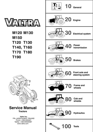
- 1. 10 20 30 40 50 60 70 80 90 100 M120 M130 M150 T120 T130 T140, T160 T170 T180 T190 Tractors Valtra Inc. FIN---44200 Suolahti, FINLAND Phone +358 2045501 Telefax +358 204550387 www.valtra.com General Engine Electrical system Power transmission Front axle and steering system Brakes Frame and wheels Cab and shields Hydraulics Service Manual Tools
- 2. 10. General 11. Layout 12. Construction 13. Maintanance 14. General technical specifications
- 3. Model Code Page 11. Layout 110 12.1.2004 T120--T190 M120--M150 7 The following supplements have been published for the Valtra T and M---series Service Manual: Order number Date of publication Notes
- 4. Model Code Page 11. Layout 110 32.1.2004 T120--T190 M120--M150 9 Layout of Service Manual Division into groups The manual is divided into groups (10---100) which are based on the make---up of the tractor. The groups are listed on the first index leaf. Example. 10. General 20. Engine, fuel and cooling systems 30. Electrical system 40. Power transmission a.s.o. The number designation for each group is given in the top left box of the respective pages (and the first figure in the code designa- tion). 410 1 50 60 70 80 90 100 Code Page Division into components or sub--groups Each group is further divided into components or sub---groups. The number and the name of each component is given in the top left box on each page (and comprise the two first figures in the code designation). Example. 41. Clutch 42. Gearbox 44. Low gear 45. Final drives etc.
- 5. Model Code Page 11. Layout 110 42.1.2004 T120--T190 M120--M150 10 Tractor model At the top of each page it is indicated for which tractor the page is valid. Code designation Three---digit code designations are used to separate the different document groups for the respective components. The same code is also used in the Time list as a reference to the text in this manual. The code designation numbers appear in the box at the top of the page and also in the headings. Example: Code 410 --- Group: power transmission (4) --- Component: clutch (41) --- Document group: general (410) Page numbers The instructions for all components are numbered in consecutive order in the right---hand box at the top of the page. The page numbers begin with page 1 for each component. 41. Clutch 15. 5. 1993 Model Code Page 205---665 410 1 Date At the top of each page there are two boxes for dates. In a case of revised issue, the date of the earlier issue is printed in the crossed---over box and and the date of the current issue is printed in the proper date box. Additions and amendments of the service manual New and up---dated pages will be continuously added to the service manual. The new pages should be inserted as indicated by the code: the first digit (also the first digit on the index leaf) indicates the group: --- the two first digits indicate the component or sub---group. --- the third digit indicates the document group for the respective components --- the page number indicates the definite position of the page within the service manual. If there are two pages with the same code and page number, it is the page with the later date in the date box and the old date in the crossed---over box which is valid or which is the current page. When an entirely new set of repair instructions is issued, it will be accompanied by instructions on where the pages should be inserted in the file.
- 6. Model Code Page 11. Layout 110 52.1.2004 T120--T190 M120--M150 11 Code designations in the Service Manual 10. General 110 Layout 120 Repairs 130 Maintenance 20. Engine 21. Engine 210 General 211 Cylinder block 212 Flywheel housing 213 Cylinder head and valve mechanism 214 Crankshaft engine 215 Counterbalance 216 Timing gear assembly 217 Lubrication system 218 Inlet and exhaust system 219 Safety instructions 22. Fuel system 220 General 222 Fuel feed pump and fuel filters 223 Injection pump and injectors 23. Cooling system 230 General 231 Cooling system 24. Engine control system 240 General 241 Changing of control unit 30. Electrical system 31. Autocontrol 5.3 310. Electrical system 311. Wiring diagram 32. Autocontrol 5.5 33. Autocontrol 6.1 330. Electrical system 331. Wiring diagram 34. Service codes 340. Autocontrol system 341. Power lift system 35. Power lift electrical system 350. General 351. Services and fault codes 36. Working hydraulics electrical system 360. General 37. Service software 370. General 40. Power transmission 41. Clutch 410. General 411. Repair instructions of the clutch 42. Gearbox 420. General 421. Repair instructions of the selector forks 423. Repair instructions of the gearbox 424. Repair instructions of the differential 44. Quick---shift gear (DPS) Reverse shuttle 4WD clutch 440. General 441. Repair instructions of the quick---shift gear. (DPS) and reverse shuttle 442. Repair instructions of the 4WD clutch 45. Final drives 450. General 451. Repair instructions of the final drives 46. Power take off 460. General 462. Repair instructions of the rear PTO 462. Repair instructions of the front PTO 50. Brake system 51. Service brakes 510. General 511. Repair instructions of the service brakes 52. Parking brake 521. Repair instructions of the parking brake
- 7. Model Code Page 11. Layout 110 62.1.2004 T120--T190 M120--M150 12 60. Front axle and steering system 61. Steering system 610 Technical data, description, tools 611 Reconditioning steering system 612 Priority valve 613 Steering cylinder 62. Powered front axle 620 Technical data, description, tools 621 Axle housing and central pivot bearing brackets 622 Drive shaft 623 Hub reduction gear 624 Differential 63. Powered front axle 630 Technical data, description, tools 64. Powered front axle 640 Technical data, description, tools 642 Drive shafts 643 Hubs 644 Differential 70 Frame and wheels 710 Frame 720 Wheels 80 Cab and shields 90. Hydraulics, power lift 91. Hydraulics 910. General 911. Repair instructions of the hydraulics 92. Valves for auxiliary hydraulics and front loader 920. General 921. Repair instructions of the auxiliary hydraulics 93. Power lift 930 General 931. Repair instructions of the front and rear power lift 100 Special tools
- 8. Model Code Page 12. Construction 120 12.1.2004 T120--T190 M120--M150 13 T120---T190 series, construction
- 9. Model Code Page 12. Construction 120 22.1.2004 T120--T190 M120--M150 14 M120---M150 series, construction
- 10. Model Code Page 12. Construction 121 12.1.2004 T120--T190 M120--M150 15 T120---T190 series, dimensions
- 11. Model Code Page 12. Construction 121 22.1.2004 T120--T190 M120--M150 16 Dimensions (mm) T 120 T 130 T 140 T 160 T 170 T 180, T190 1. With front tyres/tires 16.9R28 16.9R28 16.9R28 460/85R30 460/85R30 460/85R30 2. With rear tyres/tires 20.8R38 20.8R38 20.8R38 20.8R42 20.8R42 20.8R42 4. Length 5148 5148 5148 5148 5148 5148 7a. Width 2338 2338 2338 2338 2338 2338 5a. Height to the roof 2960 2960 2960 3030 3030 3030 5. Height to the exhaust pipe 2900 2900 2900 2965 2965 2910 3. Wheel base 2748 2748 2748 2748 2748 2748 8. Ground clearance (front axle) 555/5151) 555/5151) 555/5151) 600/5601) 600/5601) 600/5601) 9. Ground clearance (rear axle) 535 535 535 600 600 600 1) With front axle suspension. Dimension from the rear axle mid point to the cab roof part is 2093 mm. Weights kg T 120 T 130 T 140 With tyres/tires 16.9R28, 20.8R38 16.9R28, 20.8R38 16.9R28, 20.8R38 Total weight (with full fuel tank and without ballast weights) 5530 5530 5650 Front axle weight (%) 2480 (45) 2480 (45) 2600 (46) Rear axle weight (%) 3050 (55) 3050 (55) 3050 (54) Weights kg T 160 T 170 T 180, T190 With tyres/tires 540/65R30, 650/65R42 540/65R30, 650/65R42 650/65R42, 540/65R30 Total weight (with full fuel tank and without ballast weights) 5950 5950 5990 Front axle weight (%) 2700 (45) 2700 (45) 2740 (46) Rear axle weight (%) 3250 (55) 3250 (55) 3250 (54) Track widths: Front 6. Track width 14.9--28/6, 14.9R28, 380/70R28, 380/85R28, 420/70R28, 420/85R28, 440/65R28, 16.9R28, 16.9--28/8, 480/65R28, 480/65R28E1, 480/70R28, 540/65R28, 540/65R28E1 + more: see operator’s manual 1540, 1635, 1740, 1835, 1940, 2035 Rear 7. Track width 8.4R38, 18.4--38/8, 18.4R42, 460/85R38, 480/70R38, 20.8R38,, 20.8--38/10, 520/70R38, 520/85R38, 520/85R42 540/65R38, 580/70R38, 480/80R42 + more: see operator’s manual 1610, 1715, 1810, 1910, 2010, 2115 Maximum permissible front--- and rear axle loadings, kg Regardless of any limitations due to the tyres/tires, with standard track widths max. speed. Tractor T120, T130 T140---T170 T180,T190 Front 4WD max 40 km/h 3300 max 8 km/h 5500 industrial front axle max 40 km/h 4500 4500 4500 max 8 km/h 6200 6200 6200 Rear, max 40 km/h 8000 9000 9000 Total weight, max 40 km/h 9000 11000 11000
- 12. Model Code Page 12. Construction 121 32.1.2004 T120--T190 M120--M150 17 M120---M150 series, dimensions www.agrimanuals.bigcartel.com
- 13. Model Code Page 12. Construction 121 42.1.2004 T120--T190 M120--M150 18 Dimensions (mm) M120 M130 M150 1. With front tyres/tires 16.9R28 16.9R28 16.9R28 2. With rear tyres/tires 20.8R38 20.8R38 20.8R38 4. Length 4898 4898 4898 7a. Width 2338 2338 2338 5a. Height to the roof 3000 3000 3000 5. Height to the exhaust pipe 2930 2930 2930 3. Wheel base 2559 2559 2559 8. Ground clearance (front axle) 530/4901) 530/4901) 530/4901) 9. Ground clearance (rear axle) 535 535 535 1) With front axle suspension Dimension from the rear axle mid point to the cab roof part is 2133 mm. Weights kg M120 M130 M150 With tyres/tires 20.8R38 20.8R38 20.8R38 Total weight (with full fuel tank and without ballast weights) 5290 2) 5290 2) 5450 Front axle weight (%) 2320 (44) 2) 2320 (44 2) 2480 (46) Rear axle weight (%) 2970 (56) 2970 (56) 2970 (54) 2) With industrial front axle 160 kg heavier, standard on model M150. Track widths: Front 6. Track width 13.6R28, 14.9R28, 14.9--28, 16.9R28, 16.9--28, 340/85R28, 380/85R28, 420/70R28, 420/85R28, 440/65R28, 480/65R28, 480/70R28, 540/65R28 1530, 1645, 1735, 1840, 1930, 2045, 2135 230/95R36 1504, 1580, 1602, 1702, 1880, 1980, 2002, 2102 14.9R28, 14.9R28 IND, 16.9R28, 14.9--28/14 FOR, 420/85R28, 480/65R28 IND 1840, 1745 Industrial front axle 6. Track width 14.9R28*, 14.9--28*, 16.9R28, 16.9--28, 380/85R28*, 420/70R28*, 420/85R28, 480/65R28, 480/70R28, 540/65R28 1530, 1625, 1730, 1830*, 1930, 2025, 2130, 2230 230/95R36 1500, 1545, 1810, 1855, 1900, 1940, 2210, 2255 500/60--26,5 FOR 1890, 1880 14.9R28, 14.9R28 IND, 14.9--28 FOR, 16.9R28, 16.9R28 IND, 16.9--28 FOR, 1870 1890 14.9R28, 14.9R28 IND, 14.9 28 FOR, 16.9R28, 16.9R28 IND, 16.9 28 FOR, 420/85R28, 480/65R28 IND, 500/65R28 FOR, 540/65R28, 540/65R28 FOR 1870, 1890 Rear 7. Track width 16.9R38, 18.4R38, 18.4--38/8, 420/85R38, 460/85R38 1510, 1610, 1715, 1810, 1910, 2010, 2115 20.8R38, 20.8--38/10, 520/70R38, 520/85R38, 540/65R38, 580/70R38 1610, 1715, 1810, 1910, 2010, 2115 600/65R38, 650/65R38 1715, 1810, 1910, 2010, 2115 270/95R48 1500, 1520, 1600, 1620, 1900, 1920, 2000, 2020 680/75R32 1714, 1810 18.4--38/14 FOR, 18.4R38, 18.4R38 IND 1650, 1875 600/65--34 FOR 1630, 1900 20.8R38, 20.8R38 IND, 20.8--38/14 FOR, 520/85R38, 600/65R38 FOR, 600/65R38 IND, 650/65R38, 650/65R38 FOR 1675, 1850 Maximum permissible front--- and rear axle loadings, kg Regardless of any limitations due to the tyres/tires, with standard track widths max. speed. Tractor M120---M150 max 40 km/h 3300 Front 4WD max 8 km/h 5500 Front 4WD industrial front axle max 40 km/h 4500 Industrial front axle max 8 km/h 6200 Rear, max 40 km/h 8000 Total weight, max 40 km/h 9000
- 14. Model Code Page 13. Maintanance 130 12.1.2004 T120--T190 M120--M150 19 General instructions for repairs Outer oil seals The Service Manual contains instructions for changing all outer oil seals, (e.g. oil seals on the PTO shaft end, on the output shaft to the front wheel drive and on the pinion shaft on the powered front axle, and so on). Sealing compound and glue If sealing compounds or glue are required for the repair work, the instructions will specify a sealing compound or glue which is readily available through specialist dealers. Some seals should be greased before fitting and the space between the lips of the seal should be filled with universal grease. If the seal is to be pushed over splines or sharp edges the seal should be protected with for example a thin plastic foil. Tightening torques and setting values All necessary tightening torques and setting values for each repair operation are given at the beginning of each repair section under the heading Technical Data. The most important values can also be found in the repair instructions. Table 1 later gives the tightening torques in order of dimension, quality and surface treatment. The values given in the table should be used if the tightening torque is not given in the repair instructions. Safety Always bear safety in mind when repairing or servicing the tractor. Use tools and lifting devices in the correct way . When you are removing tractor components or splitting the tractor, every tractor part must be supported in such a way, that no risk of accident exists. Avoid working under the supported tractor part if it is not absolutely necessary. When supporting the tractor the centre of gravity of the frame part must always be checked. For instance the wedges must always be fitted between front axle and engine to prevent axle oscillation when splitting the front frame of the tractor. Trouble---shooting The following procedure, combined with the information contained in the workshop manual will be helpful in tracing faults accu- rately. It consists of following a number of logical steps to locate and correct the problem. a) Determine the problem b) List possible causes c) Differentiate the causes d) Conduct checks in logical order to determine the exact cause e) Consider approximate remaining service life against cost of parts and labour. f) Make any necessary repairs. g) Recheck the parts and functions for correct operation
- 15. Model Code Page 13. Maintanace 130 22.1.2004 T120--T190 M120--M150 20 Handling of heavy components Unless otherwise specified, all removals should be accom- plished using adjustable lifting equipment. All supporting slings must be parallel to each other and as near vertical as possible in relation to the object being lifted. However, where slings are of a far greater capacity than the weight of the load to be fitted, a triangular lifting arrangement may be used. When removing a component at an angle, remember that the capacity of an eyebolt is reduced when the angle between the supporting members and the object becomes less than 90˚. Oikein Rätt Right Richtig Giusto Väärin Fel Wrong Falsch Sbagliato Correct Teisingai Mauvais Netei- singai B C D A Forged eyebolt support A. Load B. Lifting shackle C. Shackle retaining plate ( 3 mm thick) D. Sleeve When necessary the forged eyebolt can be supported in the way shown in figure above. Sleeve D may or may not be welded to plate. Warning! If a part resists removal, check that allnuts andbolts have been removed and that there is no interference from ad- jacent parts. Cleanliness Toensure long life of a machine, it is important tokeep dirt and foreign material out of its vital working components. Precau- tions must be taken to safeguard against this. Enclosed com- partments, seals and filters have been provided to keep the supply of air, fuel and lubricant clean. These protective de- vices must not be removed. Whenever hydraulic, fuel, lubricating oil or lines are discon- nected, clean the point of disconnection and the surrounding area. As soon as a line has been disconnected, cap, plug or tape the line or opening to prevent the ingress of foreign ma- terial. The same cleaning and covering precautions should be taken when access covers or inspection plates are removed. Clean and inspect all parts. Make sure that all passages and holes are clear. Cover all parts to keep them clean. Make sure parts are clean when they are reassembled. Leave new parts in their wrapping until they are actuallyneeded forreassembly Assembly When reassembling a machine, complete each step in se- quence. never partially assemble one part then start to as- semble another. Make all recommended adjustments. Al- ways check the job on completion to ensure that nothing has been overlooked. Recheck the various adjustments before putting the machine back into service. Note! Before fitting new parts, remove rust preventative com- pound from all machined surfaces (usually ”peel---off sub- stances). Lubrication Where applicable, fill the compartments of repaired or re- newed components with the quantity, type and grade of clean lubricant recommended in the routine maintenance section of the Operator’s Manual. Shims When shims are removed, tie them together and identify their location. Keep shims clean and take care not to bend them before refitting them. Gaskets Make sure that the holes in gaskets line up with lubricating oil passages in the mating parts. If gaskets have tobe made, use material of the correct type and thickness. Make sure that holes are punched in the right places. Incorrectly punched gaskets can cause serious damage. Lip type rubber seals Lubricate the lips of lip---type rubber seals with oil before fit- ment. Do not use grease on seals, except for grease seals.
- 16. Model Code Page 13. Maintanace 130 32.1.2004 T120--T190 M120--M150 21 4 5 3 2 1 The main parts of lip---type seal: 1. Case 2. Sealing element 3. Ring spring The figure above shows the construction of a simple lip---type seal. The cross section shows the heel (4) and the toe (5), used to identify the sides of a single element seal. With a few exceptions, the toe of a single---lip is located on the lubricant side. Some seals have a second auxiliary lip which has no spring. Cables and wires When removing or disconnecting a group of cables or wires, label each one to ensure correct refitment. Locking devices Correct and incorrect use of retainers Correct and incorrect method of fitting and bending locking tabs. Slackening of nuts and bolts is prevented by mechanical means such as lockwashers, tab washers and cotter pins, or by Loctite---type locking agents. Flat retainers must be installed properly to be effective. Bend one end of the retainer against the edge of the part. Bend the other end against one of the nut or bolt head.Always fit new retainers in compartments which house moving parts. When fitting lockwashers on aluminium housings, place a flat washer between the lockwasher and the housing. Note! 1) Never fit a lockwasher (Grower, fan, spring, etc.) under a nut or bolt to which a specified torque has to be applied. 2) Always thoroughly degrease components before applying Loctite type locking agents. Bushes and press fits Do not fit bushes with a hammer alone. Use a suitable fitting tool and a hammer or, better still, a press if possible. When using a press, ensure that pressure is applied directly in line with the bore. If the ring has an oil hole, take care toalign it with the oil hole in the mating part. When press fitting a part into another part, lubricate the mating surfaces. Tapered parts should be assembled dry. Before assembly, check that the tapers are dry and free from burrs. Fitting bolts in blind holes Use bolts of the correct length. A bolt which is too long may ”bottom” before the head comes into contact with the part it is to hold: this will cause damage to the threads. If a bolt is too short, there may not be enough threads engaged to hold the part securely.
- 17. Model Code Page 13. Maintanace 130 42.1.2004 T120--T190 M120--M150 22 Conversion table for common units Quantities and units Conversion factors Overall and detail dimensions millimetres (mm) 100 mm=3,94 inches 1 inch=25,4 mm Short distances e.g. turning circles metres (m) 1 m=3,28 ft 1 ft=0,305 m Travel distances kilometres 1 km=0,62 mile 1 mile=1,61 km Tractor weights, axle loadings kilograms (kg) 1 kg=2,2 lbs 1 lb=0,454 kg Travel speed kilometres per h (km/h) 1 km/h=0,62 mph 1 mph=1,61 km/h Drawbar pull kilonewtons (kN) 1 kN=224,8 lbs 1 lb=4,448 N Power (identified by such terms as crankshaft power, 1 kW=1,34 hp pto power, belt power, drawbar power, indicating 1 hp=0,746 kW the point at which the measurement was taken) kilowatts (kW) Engine torque newton metres (Nm) 1 Nm=0,74 ft lb 1 ft lb=1,356 Nm Fuel consumption by weight (kilograms per hr, kg/h) 1 kg/h=2,2 lb/hr (by volume) litres per hr (l/h) 1 lb=0,454 kg 1 l/h=0,22 gal/hr 1 gal=4,54 l Fuel economy (specific fuel consumption) 304 g/kWh=0,5 lb/hp hr grams per kilowatt hr (g/kWh) Engine displacement litres (l) 1 l=61,02 m cu in 100 cu in=1,639 l Hydraulic pump 1 MPa=145 psi pressure---mecapascal (MPa) 1000 psi=6,9 MPa delivery---millimetres per sec (ml/s) 100 ml/s=1,32 gpm 1 gpm=75,77 ml/s Tyrepressure---kilopascal (kPa) 100 kPa=14,5 psi 1 psi=6,9 kPa Area acres---hectare To convert multiply by 0,404686 Volume bushel---litre To convert multiply by 39,3687 Quantity pound per acre---kilogram per hectare Multiply by 1,12085 Volume Multiply by superficial foot---cubic metre 0,002360
- 18. Model Code Page 13. Maintanace 130 52.1.2004 T120--T190 M120--M150 23 Valtra service Maintenance Correct maintenance at the right time is essential for reliable operation of the tractor. Maintenance costs are small com- pared with repair costs resulting from lack of maintenance. The most important measures are those which you carry out yourself which include lubrication and various checks and ad- justments. The service intervals shown apply for normal operating condi- tions but in more severe conditions servicing should be car- ried out more frequently. Carrying out the maintenance Other points: --- Lubricate according to chart --- Road test tractor. Check during the road test all the func- tions of the controls and instruments. After the road test, check for oil leaks, check the coolant and fuel system. --- Always stop the engine before starting work. --- Apply the parking brake to ensure the tractor cannot move. If the ground is uneven the wheels should be block- ed. --- Wash down the tractor first so that the work can be done easily and quicker. NOTE: Do not let the water get to the electrical equip- ment when washing the machine. --- Always observe the utmost cleanliness in all maintenance work. Thoroughly wipe off filler caps and plugs as well as surrounding parts of the tractor before filling up with fuel or oil. arge amounts of dirt (e.g. heavily clogged filters) can point to a fault which could cause extensive and costly repairs if not corrected in time. --- When carrying out checks the tractor should stand on level ground. --- Levels should be checked in the morning when the oil is cold and has had time torun down tothe bottom of the unit concerned. --- When changing the oil, bear in mind that the oil can be very hot when it drains from the tractor. Waste oil and oil filters should be handled carefully and disposed of pro- perly. --- Avoid touching the exhaust manifold, turbocharger and other hot parts of the engine. --- Keep the engine surfaces clean in order to avoid the risk of fire. --- The fuel, lubricating oil and coolant cause irritation to skin if in contact for long periods. --- After completion of service work replace all safety covers etc. Greasing lubricating points fitted with grease nip- ples --- Always clean the grease nipples before applying the grease gun. --- Apply grease through the nipples until clean grease oozes out (unless otherwise instructed). --- Wipe away superfluous grease which has been pressed out at the lubricating point. --- Preferably carry out lubrication with bearing points and joints unloaded and with the bearings in different position- s. Scheduled maintenance The maintenance schedule begins with the running hour meter reading 0. This means that maintenance scheduled at 250 h intervals is performed at meter readings 250 h, 500 h etc., even if the same procedures were carried out at the 50 h maintenance. At the 500 h maintenance, for example, the daily, weekly and 250 hour maintenance procedures must also be undertaken. Service inspection (after 100 hours) Your dealer gives a cost---free service inspection (excluding oil and filter costs) to all new tractors after 100 hours running. The service procedure is as follows: 20 Engine: --- Change engine oil and filter --- Change prefilter, fuel system --- Change fuel filter 40 Power transmission: --- Change pressure filters and hydraulic return filter 60 Front axle and steering system: --- Change oil in differential --- Change oil in hubs
- 19. Model Code Page 13. Maintanance 130 62.1.2004 T120--T190 24 Recommended fuel and lubricants All volumes are with filters. Part of machine Valtra--grade SAE--grade API--grade Volume, when changing (liter) Engine --- T180, T190 Valtra Engine E 10W---30: ---20˚C...+30˚C 15W---40: ---10˚C...+40˚C CG---4 CH---4 19 Hydraulic system and transmission Valtra Transmission HT 60: ---30˚C...+30˚C HT 100: ---10˚C...+40˚C GL---4 (G2---98) 45 (55 max) (extra max 65) Industrial front axle --- differential Valtra Axle 80W---90 GL---5 (LS) 7 --- hub reduction gears ( ) 2x1.5 Front PTO (extra equipment)( q p ) --- T180, T190 Shell Donax TX 2.2 Fuel tank Diesel fuel which conforms to EN 590 norm 165 --- Extra fuel tank Diesel fuel which conforms to EN 590 norm 170 Cooling system water + anti freeze agent (standard ASTM D3306---86a or BSg y --- T180, T190 water + anti freeze agent (standard ASTM D3306 86a or BS 6580:1985) 31 Brake fluid reservoir Brake fluid SAE J1703 0,3 Windscreen washer Washer fluid 11 Part of machine Valtra--grade SAE--grade API--grade Volume, when changing (liter) Engine --- T120---T170 Valtra Engine E 10W---30: ---20˚C...+30˚C 15W---40: ---10˚C...+40˚C CG---4 CH---4 19 Hydraulic system and transmission Valtra Transmission HT 60: ---30˚C...+30˚C HT 100: ---10˚C...+40˚C GL---4 (G2---98) 45 (55 max) (extra max 65) Powered front axle --- differential 8 --- hub reduction gears 2x1 --- differential industrial axle (standard on T140---T170) Valtra Axle 80W---90 GL---5 (LS) 6 --- hub reduction gears ind. axle (standard on T140---T170) 2x1.5 Front PTO (extra equipment)( q p ) --- T120---T170 Shell Donax TX 2.2 Fuel tank Diesel fuel 165 --- Extra fuel tank Diesel fuel 170 Cooling systemg y --- T120, T130 water + anti freeze agent (standard ASTM D3306---86a or BS 28 --- T140 water + anti freeze agent (standard ASTM D3306 86a or BS 6580:1985) 30 --- T160, T170 ) 27 Brake fluid reservoir Brake fluid SAE J1703 0,3 Windscreen washer Washer fluid 11
- 20. Model Code Page 13. Maintanance 130 72.1.2004 M120--M150 25 All volumes are with filters. Part of machine Valtra--grade SAE--grade API--grade Volume, when changing (liter) Engine --- M120---M150 Valtra Engine E 10W---30: ---20˚C...+30˚C 15W---40: ---10˚C...+40˚C CG---4 CH---4 15 Hydraulic system and transmission Valtra Transmission HT 60: ---30˚C...+30˚C HT 100: ---10˚C...+40˚C GL---4 (G2---98) 45 (55 max) (extra max 65) Powered front axle --- differential 8 --- hub reduction gears 2x1 Industrial front axle (standard on M150) --- differential Valtra Axle 80W---90 GL---5 (LS) 7 --- hub reduction gears 2x1.5 Front PTO (extra equipment)( q p ) --- M120---M150 Shell Donax TX 2.2 Fuel tank Diesel fuel which conforms to EN 590 norm 165 --- Extra fuel tank Diesel fuel which conforms to EN 590 norm 170 Cooling system water + anti freeze agent (standard ASTM D3306---86a or BSg y --- M120---M150 water + anti freeze agent (standard ASTM D3306 86a or BS 6580:1985) 22 Brake fluid reservoir Brake fluid SAE J1703 0,3 Windscreen washer Washer fluid 11
- 21. Model Code Page 13. Maintanance 130 82.1.2004 T120--T190 M120--M150 26 Oil recommendations according to outdoor temperature When starting the tractor in a warm garage, oil meant for warmer areas may be used. 10W---30 80W---90 15W---40 / HT100 ---30˚C ---20˚C ---10˚C 0˚C +10˚C +20˚C +30˚C +40˚C HT 60 The synthetic bio oil can be used in the transmission/hydraulics, which conforms to OECD 301 A---F norm. Quality requirements of engine fuel Property Requirement Test standard Specific weight +15˚C, ISO 12185 0,82...0,86 kg/litre ASTM D 4052, EN Viscosity +40˚C, 445, ISO 31041 1,2...4,5 mm2/s ASTM D Sulphur content max. 0,2 p---% ASTM D 4294, ISO 8754 Cetane number 4737 min. 51 ASTM D Water content max. 200 mg/kg ASTM D 1744 Fuel --- The properties of light fuel oil that is only intended for warming use do not meet the requirements of modern die- sel engines and cannot be used as fuel. --- In particular, distributor---type injector pumps require the fuel to have sufficient lubricity, because they do not have oil lubrication in the same way as typical multi---element pumps. Adding oil to diesel fuel is not recommended, be- cause it causes carbon build---up, and if oil is mixed with even a small amount of water it will clog the filter. --- Additionally, various fuel quality requirements imposed by taxation and seasonal changes have tobetaken intoconsi- deration. Fuel storage --- Storing and distributing fuel must be arranged in condi- tions where no water or impurities can enter the storage tanks. The storage tanks must be installed in a slanted position, so that water and impurities are collected at the opposite end from the suction pipe of the pump. The suc- tion pipe of the pump should not reach the bottom of the tank. --- Water must be periodically drained from the tank in order to prevent problems. Refueling at the same time the tank is being refilled must be avoided without exception. --- When the tank is filled with winter---quality fuel in good time, the engine is guaranteed to run flawlessly during the cold season. Filter system --- The engine’s standard filter system gives sufficient protec- tion for the injection system from impurities that can be present in well---tended distribution systems. --- The control of distributor---type injection pumps is based on internal pressure, which will drop if the fuel system is clogged. If the pilot pressure drops too low, engine power is reduced, smoke increased and starting becomes more difficult. Additionally, water in the injection system will de- stroy it in a very short time. For this reason, the water trap and the filters must always be serviced according to the specified amount of running hours. --- It is alsoimportant always touse original Valtra (or Sisu Die- sel) fuel filters. They guarantee sufficient filtration, prevent- ing impurities from damaging the fuel system. There are many cheap filter kits (so---called pirates) on the market, with lower quality and performance in ordertominimisethe cost. Among other things, the quality and amount of filter paper are often insufficient. There are also often danger- ous defects in the basic structure that may cause expens- ive damage even in a short period of time.
- 22. Model Code Page 13. Maintanance 130 92.1.2004 T120--T190 M120--M150 27 Grease Always use the following greases in Valtra tractors. Each point requires it own type of grease. Valtra Grease, Universal grease Lithium---based universal grease. Is suitable for greasing all heavy machines. ---30˚ ... +130˚C Universal grease of high quality, lithium based grease forvehi- cle use. It is recommended for greasing wheel bearings, chassis water pumps, catepillar rollers etc. The grease is ad- hesive, protects against corrosion and resists water and va- rying temperatures. Temperature range is ---30˚ ... +130˚C. Valtra Calsium LF, Calsium Grease LF Is suitable for greasing all heavy machines. Long fibre grease. Colour red. ---20˚ ... +60˚C Calsium LF is of long fibre, high quality and calsium based universal grease for vehicle use. It is recommended for grea- sing chassis, water pumps, pins etc.The grease is adhesive, protects against corrosion and resists water and varying tem- peratures. Temperature range is ---20˚ ... +60˚C. Valtra Grease Moly Is suitable for greasing all heavy machines. Lithium---ba- sed universal grease. ---30˚ ... +130˚C Universal grease of high quality, lithium based grease forvehi- cle use. It is recommended for greasing wheel bearings, chassis water pumps, catepillar rollers etc. The grease is ad- hesive, protects against corrosion and resists water and va- rying temperatures. Temperature range is ---30˚ ... +130˚C. Avoid repeating skin contact. Protect nature and take care of empty packages.
- 23. Model Code Page 13. Maintanance 130 102.1.2004 T120--T170 28 Maintenanceschedule The same numbering system as used on the detached main- tenance schedule are placed in brackets where applicable. Daily maintenance 1. Check engine oil level. 2. Check coolant level, radiator fins and front grilles of the engine cover. 3. Check for oil and fluid leaks. Weekly maintenance 4. Grease three---point linkage and towing device (towing devices are available as extra equipment). 5. Grease brake mechanism (high pressure grease). 6. Grease front axle mounting nipples (all models) and steering knuckles of industrial axle. 7. Check oil level in transmission and hydraulics. 8. Check belt/belts tightness (replace belts if necessary). 9. Check fuel system prefilter and sediment bowl. 10. Check electrolyte level in battery. 11. Grease the drive shaft joint nipples of the agricultural front axle. 12. Check tyre/tire pressure. Every 500 hours 13 Grease door hinges. 14. Check brake fluid level. 15. Clean cab ventilation air filter (more often when needed). 16. Check wheel nuts tightness. 17. Change engine oil and filter (or yearly), in extremely dusty conditions at 250---hour. 18. Check brake pedal free travel. 19. Change pressure filters of the transmission and hydraulics and also hydraulic return oil filter or if the filter indicator lamp illuminates. 20. Check oil level in front axle differential and hubs. NOTE: When carrying out servicing you must follow the service intervals, you must also do all previously men- tioned items. For example, when doing 500 hours service you must also do the servicing required at weekly and daily. 217 17 1116 12179171551612 20 20 6 66811 20 16 12 6214 10 19185161912 4 7 4 IND 1 20
- 24. Model Code Page 13. Maintanance 130 112.1.2004 T120--T170 29 Every 1000--hour 21. Change oil in transmission/hydraulics and clean suction strainer. 22. Change oil in front axle differential and hubs. 23. Change cab ventilation air filter and recirculation filter. 24. Change fuel filter and prefilter. 25. Change air filter and safety filter. 26. Grease flywheel ring gear. 27. Check/adjust front wheel toe---in. 28. Clean fuel tank. 29. Adjust valves. 30. Change transmission housing breather. 31. Accelerator pedal calibration and checking of power shuttle operation. 32.Tighten frame nuts and bolts. Every 2000 hours or every other hour 33. Clean cooling system. 34. Change brake fluid. 35. Check and clean injectors. 36. Check/change engine vibration damper on models which have rubber vibration dampers NOTE: When carrying out servicing you must follow the service intervals, i.e., you must also do all previously mentioned items. For example, when doing 2000 hours service you must also do the servicing required at 1000, 500, weekly and daily. 21 21 22 IND 22 23 23 22 22 22 2421 21 22 25 26 27 27 27 27 28 29 30 31 31 33 33 33 34 35 36
- 25. Model Code Page 13. Maintanance 130 122.1.2004 T180--T190 30 The same numbering system as used on the detached main- tenance schedule are placed in brackets where applicable. Daily maintenance 1. Check engine oil level. 2. Check coolant level, radiator fins and front grilles of the engine cover. 3. Check for oil and fluid leaks. Weekly maintenance 4. Grease three---point linkage and towing device (towing devices are available as extra equipment). 5. Grease brake mechanism (high pressure grease). 6. Grease front axle mounting nipples and steering knuckles of industrial axle. 7. Check oil level in transmission and hydraulics. 8. Check belt/belts tightness (replace belts if necessary). 9. Check fuel system prefilter and sediment bowl. 10. Check electrolyte level in battery. 11. Check tyre/tire pressures. Every 500 hours 12. Grease door hinges. 13. Check brake fluid level. 14. Clean cab ventilation air filter (more often when needed). 15. Check wheel nuts tightness. 16. Change engine oil and filter (or yearly), in extremely dusty conditions at 250---hour. 17. Check brake pedal free travel. 18. Change pressure filters of the transmission and hydraulics and also hydraulic return oil filter or if the filter indicator lamp illuminates. 19. Check oil level in front axle differential and hubs. NOTE: When carrying out servicing you must follow the service intervals, you must also do all previously men- tioned items. For example, when doing 500 hours service you must also do the servicing required at weekly and daily. 5 14 9 1 2 5 10 13 2 6 6 8 6 7 4 4 11 11 11 11 15 15 15 15 1616 17 1818 19 1919 6 16 16
- 26. Model Code Page 13. Maintanance 130 132.1.2004 T180--T190 31 Every 1000--hour 20. Change oil in transmission/hydraulics and clean suction strainer. 21. Change oil in front axle differential and hubs. 22. Change cab ventilation air filter and recirculation filter. 23. Change fuel filter and prefilter. 24. Change air filter and safety filter. 25. Grease flywheel ring gear. 26. Check/adjust front wheel toe---in. 27. Clean fuel tank. 28. Adjust valves. 29. Change transmission housing breather. 30. Checking of power shuttle operation. 31. Tighten bolts and screws of the tractor frame. Every 2000 hours or every other hour 32. Clean cooling system. 33. Change brake fluid. 34. Check and clean injectors. NOTE: When carrying out servicing you must follow the service intervals, i.e., you must also do all previously mentioned items. For example, when doing 2000 hours service you must also do the servicing required at 1000, 500, hours, weekly and daily. 20 20 20 20 21 21 2122 22 23 24 25 32 26 27 28 29 30 32 32 21 33 34 26
- 27. Model Code Page 13. Maintanance 130 142.1.2004 M120--M150 32 The same numbering system as used on the detached main- tenance schedule are placed in brackets where applicable. Daily 1. Check engine oil level 2. Check coolant level, radiator fins and front grilles of the engine cover 3. Check for oil and fuel leaks Weekly 4. Grease three---point linkage and towing device (towing devices are available as extra equipment) 5. Grease brake mechanism (high pressure grease) 6. Grease front axle mounting nipples (all models) and drive shaft joint nipples of the agricultural front axle 7. Check oil level in transmission and hydraulics 8. Check belt/belts tightness (replace belts if necessary) 9. Check fuel system prefilter and sediment bowl 10. Check electrolyte level in battery 11. Check tyre/tire pressures Every 500 hours 12. Grease door hinges 13. Check brake fluid level 14. Clean cab ventilation air filter (more often if needed) 15. Check wheel nuts tightness 16. Change engine oil and filter (or yearly), in extremely dusty conditions at 250---hour 17. Check brake pedal free travel 18. Change pressure filters of the transmission and hydraulics and also hydraulic return oil filter or if the filter indicator lamp illuminates 19. Check oil level in front axle differential and hubs NOTE: When carrying out servicing you must fol- low the service intervals, you must also do all previously mentioned items. For example, when doing 500 hours service you must also do the servicing required at weekly and daily. 1 2 4 4 5 5 2 6 6 7 8 9 10 611 11 11 1113 141615 15 15 15 16 1718 18 19 19 16 16
- 28. Model Code Page 13. Maintanance 130 152.1.2004 M120--M150 33 Every 1000 hours / yearly 20. Change oil in transmission/hydraulics and clean suction strainer 21. Change oil in front axle differential and hubs 22. Change cab ventilation air filter and recirculation filter 23. Change fuel filter and prefilter 24. Change air filter and safety filter 25. Grease flywheel ring gear 26. Check/adjust front wheel toe---in 27. Clean fuel tank 28. Adjust valves 29. Change transmission housing breather 30. Accelerator pedal calibration and checking of power shuttle operation 31. Tighten frame nuts and bolts Every 2000 hours / every other year 32. Clean cooling system 33. Change brake fluid 34. Check and clean injectors NOTE: When carrying out servicing you must follow the service intervals, i.e., you must also do all previously mentioned items. For example, when doing 2000 hours service you must also do the servicing required at 1000, 500 hours, weekly and daily. 21 21 20 20 21 2122 22 23 24 25 26 27 27 28 29 30 32 263233 34 30 32 21 26 21 26 21
- 29. Model Code Page 14. Common technical specifications 140 12.1.2004 T120--T190 M120--M150 35 Tractor model T120 T130 T140 T160 T170 T180 T190 Engine type 66 ET 66 ET 66ETA 66ETA 74 ETA 74ETA 74ETA. . . . . . . . . . . . . . . . . . . . . . . . . . . . . . . . . . . . . . . . . . . Compression pressure (MPa) 16,5:1 16,5:1 16,5:1 16,5:1 16,5:1 16,5:1 16,5:1. . . . . . . . . . . . . . . . . . . . . . . . . . . . . . Oil pressure, normal (kPa) 250---400 250---400 250---400 250---400 250---400 250---400 250---400. . . . . . . . . . . . . . . . . Oil pressure, min. (kPa) 100 100 100 100 100 100 100. . . . . . . . . . . . . . . . . . . . . . . . . . . . . . . . . . . . . . . . . . . . . . . . Clearance, induction valve (mm) 0,35 0,35 0,35 0,35 0,35 0,35 0,35. . . . . . . . . . . . . . . . . . . . . . . . . . . . . . . . . . . . . Clearance, exhaust valve (mm) 0,35 0,35 0,35 0,35 0,35 0,35 0,35. . . . . . . . . . . . . . . . . . . . . . . . . . . . . . . . . . . . . . Injector opening pressure (MPa) 27 27 27 27 27 27 27. . . . . . . . . . . . . . . . . . . . . . . . . . . . . . . . . . . . . . . . . . . . . . . Injector setting pressure (MPa) 27,8 27,8 27,8 27,8 27,8 27,8 27,8. . . . . . . . . . . . . . . . . . . . . . . . . . . . . . . . . . . . . . . Fitting position º BTDC (static) 5º 5º 5º 5º 5º 5º 5º. . . . . . . . . . . . . . . . . . . . . . . . . . . . . . . . . . . . . . . . . . . . . . . . . Engine speed, idle (rpm) 850 850 850 850 850 850 850. . . . . . . . . . . . . . . . . . . . . . . . . . . . . . . . . . . . . . . . . . . . . . . Engine max. speed (rpm) 2400 2500 2000 2300 2300 2300 2300. . . . . . . . . . . . . . . . . . . . . . . . . . . . . . . . . . . . . . . Battery voltage (V) 12 12 12 12 12 12 12. . . . . . . . . . . . . . . . . . . . . . . . . . . . . . . . . . . . . . . . . . . . . . . . . . . . . . . . . . . Capacity (Ah) 174 174 174 174 174 174 174. . . . . . . . . . . . . . . . . . . . . . . . . . . . . . . . . . . . . . . . . . . . . . . . . . . . . . . . Acceleator pedal free play (mm) PTO output at 540 rpm/min. (kW) PTO output at 1000 rpm/min. (kW) 71 82 89 99 104 116 129. . . . . . . . . . . . . . . . . . . . . . . . . . . . . . . . . . . . . . . . . . . Brake pedal free play (mm) 70---80 70---80 70---80 70---80 70---80 70---80 70---80. . . . . . . . . . . . . . . . . . . . . . . . . . . . . Parking brake free play (mm) Toe---in (mm) 0---2 0---2 0---2 0---2 0---2 0---2 0---2. . . . . . . . . . . . . . . . . . . . . . . . . . . . . . . . . . . . . . . . . . . . . . . . . . . . . . Ratio, front axle/rear axle, 40km/h) 1,309 1,309 --- 1,327 1,327 1,327 1,327. . . . . . . . . . . . . . . . . . . . . . . . . . . . . . . . . Ratio, front axle/rear axle, 50km/h) 1,315 1,315 1,320 1,320 1,320 1,320 1,320. . . . . . . . . . . . . . . . . . . . . . . . . . . . . . Max. working pressure (steering, MPa) 14 14 14 14 14 14 14. . . . . . . . . . . . . . . . . . . . . . . . . . . . . . . . . . . . . . . . . . Low pressure circuit max. pressure (MPa) 1,8 1,8 1,8 1,8 1,8 1,8 1,8. . . . . . . . . . . . . . . . . . . . . . . . . . . . . . . . . . . Low pressure circuit pump capacity at max. engine speed (l/min.) 28 28 25 30 30 30 30. . . . . . . . . . . . . . . . . . . . . . . . . . . . . . . . . . . . . . . . . . . . . . . . . . High pressure circuit max. pressure (MPa) 19,6 19,6 19,6 19,6 19,6 19,6 19,6. . . . . . . . . . . . . . . . . . . . . . . . . . . . . Shock valve opening pressure of pump avautumispaine (MPa) 23 23 23 23 23 23 23. . . . . . . . . . . . . . . . . . . . . . . . . . . . . . . . . . . . . . . . . . . . . . . . High pressure circuit pump capacity at max. engine speed (l/min.) 91 91 82 87 87 87 87. . . . . . . . . . . . . . . . . . . . . . . . . . . . . . . . . . . . . . . . . . . . . . . . . . Hydraulic linkage max. lifting force (kN) 77 77 77 77 77 77 77. . . . . . . . . . . . . . . . . . . . . . . . . . . . . . . . . . . . . . . . . Capacities (l) Engine 6,6 6,6 6,6 6,6 7,4 7,4 7,4. . . . . . . . . . . . . . . . . . . . . . . . . . . . . . . . . . . . . . . . . . . . . . . . . . . . . . . . . . . . . . . . Cooling system 28 28 30 27 27 31 31. . . . . . . . . . . . . . . . . . . . . . . . . . . . . . . . . . . . . . . . . . . . . . . . . . . . . . . . . . . . . . Air conditioning 1,4 1,4 1,4 1,4 1,4 1,4 1,4. . . . . . . . . . . . . . . . . . . . . . . . . . . . . . . . . . . . . . . . . . . . . . . . . . . . . . . . . Transmission 45 45 45 45 45 45 45. . . . . . . . . . . . . . . . . . . . . . . . . . . . . . . . . . . . . . . . . . . . . . . . . . . . . . . . . . . . . . . Fillings (l) Differential 8 8 6/8 6/8 6/8 6/8 6/8. . . . . . . . . . . . . . . . . . . . . . . . . . . . . . . . . . . . . . . . . . . . . . . . . . . . . . . . . . . . . . . . . Poles 2x1 2x1 2x1,5 2x1,5 2x1,5 2x1,5 2x1,5. . . . . . . . . . . . . . . . . . . . . . . . . . . . . . . . . . . . . . . . . . . . . . . . . . . . . . . . . Fuel tank 165 165 165 165 165 165 165. . . . . . . . . . . . . . . . . . . . . . . . . . . . . . . . . . . . . . . . . . . . . . . . . . . . . . . . . . . . Filters service (change) intervals (h) Oil filter 500 500 500 500 500 500 500. . . . . . . . . . . . . . . . . . . . . . . . . . . . . . . . . . . . . . . . . . . . . . . . . . . . . . . . . . . . . Fuel filter 1000 1000 1000 1000 1000 1000 1000. . . . . . . . . . . . . . . . . . . . . . . . . . . . . . . . . . . . . . . . . . . . . . . . . . . . . Air filter 1000 1000 1000 1000 1000 1000 1000. . . . . . . . . . . . . . . . . . . . . . . . . . . . . . . . . . . . . . . . . . . . . . . . . . . . . . Safety filter 1000 1000 1000 1000 1000 1000 1000. . . . . . . . . . . . . . . . . . . . . . . . . . . . . . . . . . . . . . . . . . . . . . . . . . . . Prefilter 1000 1000 1000 1000 1000 1000 1000. . . . . . . . . . . . . . . . . . . . . . . . . . . . . . . . . . . . . . . . . . . . . . . . . . . . . . . Recirculation filter 1000 1000 1000 1000 1000 1000 1000. . . . . . . . . . . . . . . . . . . . . . . . . . . . . . . . . . . . . . . . . . . . . . Pressure filters 500 500 500 500 500 500 500. . . . . . . . . . . . . . . . . . . . . . . . . . . . . . . . . . . . . . . . . . . . . . . . . . . . . . . Return oil filter 500 500 500 500 500 500 500. . . . . . . . . . . . . . . . . . . . . . . . . . . . . . . . . . . . . . . . . . . . . . . . . . . . . . . . Transmission housing breather 1000 1000 1000 1000 1000 1000 1000. . . . . . . . . . . . . . . . . . . . . . . . . . . . . . . . . . . Tightening torques (Nm) Cylinder head bolts and nuts 1) 1) 1) 1) 1) 1) 1). . . . . . . . . . . . . . . . . . . . . . . . . . . . . . . . . . . . . . . . . . . . . . . . . . . . Main bearing screws 200 200 200 200 200 200 200. . . . . . . . . . . . . . . . . . . . . . . . . . . . . . . . . . . . . . . . . . . . . . . . . . Connecting rod screws 40+90° 40+90° 40+90° 40+90° 40+90° 40+90° 40+90°. . . . . . . . . . . . . . . . . . . . . . . . ≥ . Flywheel housing screws (M12/M10) 110/60 110/60 110/60 110/60 110/60 110/60 110/60. . . . . . . . . . . . . . . . . . . . . Crankshaft nut 1000 1000 1000 1000 1000 1000 1000. . . . . . . . . . . . . . . . . . . . . . . . . . . . . . . . . . . . . . . . . . . . . . . . Exhaust manifold screws 50 50 50 50 50 50 50. . . . . . . . . . . . . . . . . . . . . . . . . . . . . . . . . . . . . . . . . . . . . . . . . . . . . Injector nozzle sleeve 60 60 60 60 60 60 60. . . . . . . . . . . . . . . . . . . . . . . . . . . . . . . . . . . . . . . . . . . . . . . . . . . . . . . . . Injector attaching nuts (on studs) 15 15 15 15 15 15 15. . . . . . . . . . . . . . . . . . . . . . . . . . . . . . . . . . . . . . . . . . . . . . . Wheel nuts 550 550 550 550 550 550 550. . . . . . . . . . . . . . . . . . . . . . . . . . . . . . . . . . . . . . . . . . . . . . . . . . . . . . . . . . Rim---wheel disc 310 310 310 310 310 310 310. . . . . . . . . . . . . . . . . . . . . . . . . . . . . . . . . . . . . . . . . . . . . . . . . . . . . . 1) 80 Nm + 90° + 90°
- 30. Model Codei Page 14. Common technical specifications 140 22.1.2004 T120--T190 M120--M150 36 Table Table 1. Tightening torques, metric standard thread (ISO) Tightening torques Nm1) Dim. Quality, surface treatment, material and so on 8.8 lubr. tol.± 8.8 Zne2) tol± 8.8 Znk3) tol. ± 10.9 lubr. tol. ± 12.9 lubr tol. ± M4 --- --- --- --- --- M5 6,4 0,6 5,7 0,5 --- 9 1 11 1 M6 11 1 10 1 12 1,2 15 1,5 18 2 M8 25 2 23 2 30 3 35 4 45 5 M10 50 5 45 5 60 5 70 7 90 10 M12 90 10 80 8 100 10 125 10 151 15 M14 140 15 125 10 160 15 200 20 240 20 M16 220 20 195 20 250 25 300 30 370 40 M18 300 30 270 30 350 35 430 40 510 50 M20 430 40 380 40 480 50 600 60 720 70 M22 570 60 500 50 650 65 800 80 970 100 M24 740 70 660 70 830 80 1030 100 1250 120 M27 1100 100 950 100 1200 120 1500 150 1800 180 M30 1500 150 1300 130 1600 160 2040 200 2500 250 1) 1 Nm=0,102 kpm 2) Zne=zinc electroplating 3) Znk=hot galvanized If the bolts differs from the standard range the values in the table must not be used.
- 31. 20. Engine 23. Cooling system 22. Fuel system 21. Engine 24. Engine control system 37
- 32. Model Code Page 21. Engine 2102.1.2004 1 T120--T190 M120--M150 39 Contents General (code 210): Technical specifications 2. . . . . . . . . . . . . . . . . . . . . . . . . . . . . . . . . . . . . . . . . . . . . . . . . . . . . . . . . . . Technical data 3. . . . . . . . . . . . . . . . . . . . . . . . . . . . . . . . . . . . . . . . . . . . . . . . . . . . . . . . . . . . . . . . . . . Tightening torques 9. . . . . . . . . . . . . . . . . . . . . . . . . . . . . . . . . . . . . . . . . . . . . . . . . . . . . . . . . . . . . . . Cylinder block 10. . . . . . . . . . . . . . . . . . . . . . . . . . . . . . . . . . . . . . . . . . . . . . . . . . . . . . . . . . . . . . . . . . . Flywheel housing 10. . . . . . . . . . . . . . . . . . . . . . . . . . . . . . . . . . . . . . . . . . . . . . . . . . . . . . . . . . . . . . . . Cylinder head 11. . . . . . . . . . . . . . . . . . . . . . . . . . . . . . . . . . . . . . . . . . . . . . . . . . . . . . . . . . . . . . . . . . . Valve mechanism 11. . . . . . . . . . . . . . . . . . . . . . . . . . . . . . . . . . . . . . . . . . . . . . . . . . . . . . . . . . . . . . . . Crank mechanism 11. . . . . . . . . . . . . . . . . . . . . . . . . . . . . . . . . . . . . . . . . . . . . . . . . . . . . . . . . . . . . . . Timing gears 12. . . . . . . . . . . . . . . . . . . . . . . . . . . . . . . . . . . . . . . . . . . . . . . . . . . . . . . . . . . . . . . . . . . . Lubrication system 13. . . . . . . . . . . . . . . . . . . . . . . . . . . . . . . . . . . . . . . . . . . . . . . . . . . . . . . . . . . . . . . Cooling system 14. . . . . . . . . . . . . . . . . . . . . . . . . . . . . . . . . . . . . . . . . . . . . . . . . . . . . . . . . . . . . . . . . . Inlet and exhaust system 15. . . . . . . . . . . . . . . . . . . . . . . . . . . . . . . . . . . . . . . . . . . . . . . . . . . . . . . . . . Work instructions: Cylinder block (code 211): Measuring cylinder liner wear 1. . . . . . . . . . . . . . . . . . . . . . . . . . . . . . . . . . . . . . . . . . . . . . . . . . . . . . Removing cylinder liner 1. . . . . . . . . . . . . . . . . . . . . . . . . . . . . . . . . . . . . . . . . . . . . . . . . . . . . . . . . . . Checking cylinder block 1. . . . . . . . . . . . . . . . . . . . . . . . . . . . . . . . . . . . . . . . . . . . . . . . . . . . . . . . . . Changing camshaft bushings 2. . . . . . . . . . . . . . . . . . . . . . . . . . . . . . . . . . . . . . . . . . . . . . . . . . . . . . Fitting plug at camshaft rear end 3. . . . . . . . . . . . . . . . . . . . . . . . . . . . . . . . . . . . . . . . . . . . . . . . . . . Oversize bushings for camshaft 3. . . . . . . . . . . . . . . . . . . . . . . . . . . . . . . . . . . . . . . . . . . . . . . . . . . . Fitting plug at camshaft rear end 3. . . . . . . . . . . . . . . . . . . . . . . . . . . . . . . . . . . . . . . . . . . . . . . . . . . Fitting cylinder liner 4. . . . . . . . . . . . . . . . . . . . . . . . . . . . . . . . . . . . . . . . . . . . . . . . . . . . . . . . . . . . . . Flywheel housing (code 212): Fitting flywheel housing 1. . . . . . . . . . . . . . . . . . . . . . . . . . . . . . . . . . . . . . . . . . . . . . . . . . . . . . . . . . . Changing crankshaft rear oil seal 1. . . . . . . . . . . . . . . . . . . . . . . . . . . . . . . . . . . . . . . . . . . . . . . . . . . Cylinder head and valve mechanism (code 213): Remocing cylinder head 1. . . . . . . . . . . . . . . . . . . . . . . . . . . . . . . . . . . . . . . . . . . . . . . . . . . . . . . . . . Removing valves 1. . . . . . . . . . . . . . . . . . . . . . . . . . . . . . . . . . . . . . . . . . . . . . . . . . . . . . . . . . . . . . . . Checking cylinder head 1. . . . . . . . . . . . . . . . . . . . . . . . . . . . . . . . . . . . . . . . . . . . . . . . . . . . . . . . . . . Changing valve guides 2. . . . . . . . . . . . . . . . . . . . . . . . . . . . . . . . . . . . . . . . . . . . . . . . . . . . . . . . . . . Machining valve seat 2. . . . . . . . . . . . . . . . . . . . . . . . . . . . . . . . . . . . . . . . . . . . . . . . . . . . . . . . . . . . . Changing valve seat rings 3. . . . . . . . . . . . . . . . . . . . . . . . . . . . . . . . . . . . . . . . . . . . . . . . . . . . . . . . . Grinding valves 3. . . . . . . . . . . . . . . . . . . . . . . . . . . . . . . . . . . . . . . . . . . . . . . . . . . . . . . . . . . . . . . . . . Fitting valves 3. . . . . . . . . . . . . . . . . . . . . . . . . . . . . . . . . . . . . . . . . . . . . . . . . . . . . . . . . . . . . . . . . . . . Fitting cylinder head 4. . . . . . . . . . . . . . . . . . . . . . . . . . . . . . . . . . . . . . . . . . . . . . . . . . . . . . . . . . . . . . Reconditioning valve mechanism 5. . . . . . . . . . . . . . . . . . . . . . . . . . . . . . . . . . . . . . . . . . . . . . . . . . . Changing camshaft / camshaft gear 5. . . . . . . . . . . . . . . . . . . . . . . . . . . . . . . . . . . . . . . . . . . . . . . . Adjusting valves 6. . . . . . . . . . . . . . . . . . . . . . . . . . . . . . . . . . . . . . . . . . . . . . . . . . . . . . . . . . . . . . . . . Crankshaft engine (code 214): Removing crankshaft 1. . . . . . . . . . . . . . . . . . . . . . . . . . . . . . . . . . . . . . . . . . . . . . . . . . . . . . . . . . . . . Checking crankshaft 1. . . . . . . . . . . . . . . . . . . . . . . . . . . . . . . . . . . . . . . . . . . . . . . . . . . . . . . . . . . . . Changing crankshaft gears 1. . . . . . . . . . . . . . . . . . . . . . . . . . . . . . . . . . . . . . . . . . . . . . . . . . . . . . . . Fitting crankshaft 2. . . . . . . . . . . . . . . . . . . . . . . . . . . . . . . . . . . . . . . . . . . . . . . . . . . . . . . . . . . . . . . . Checking element of the rubber damber 3. . . . . . . . . . . . . . . . . . . . . . . . . . . . . . . . . . . . . . . . . . . . . Viscose type vibration damber 3. . . . . . . . . . . . . . . . . . . . . . . . . . . . . . . . . . . . . . . . . . . . . . . . . . . . . Changing crankshaft pulley / vibration damper 4. . . . . . . . . . . . . . . . . . . . . . . . . . . . . . . . . . . . . . . Removing pistons together with connecting rods 5. . . . . . . . . . . . . . . . . . . . . . . . . . . . . . . . . . . . . Changing connecting rod bearings 5. . . . . . . . . . . . . . . . . . . . . . . . . . . . . . . . . . . . . . . . . . . . . . . . . Changing connectiing rod 5. . . . . . . . . . . . . . . . . . . . . . . . . . . . . . . . . . . . . . . . . . . . . . . . . . . . . . . . . Changing piston rings 6. . . . . . . . . . . . . . . . . . . . . . . . . . . . . . . . . . . . . . . . . . . . . . . . . . . . . . . . . . . . Checking pistons 7. . . . . . . . . . . . . . . . . . . . . . . . . . . . . . . . . . . . . . . . . . . . . . . . . . . . . . . . . . . . . . . . Fitiing piston together with connecting rod 7. . . . . . . . . . . . . . . . . . . . . . . . . . . . . . . . . . . . . . . . . . . Changing starter ring gear on flywheel 9. . . . . . . . . . . . . . . . . . . . . . . . . . . . . . . . . . . . . . . . . . . . . . Fitting flywheel 9. . . . . . . . . . . . . . . . . . . . . . . . . . . . . . . . . . . . . . . . . . . . . . . . . . . . . . . . . . . . . . . . . .
- 33. Model Code Page 21. Engine 2102.1.2004 2 T120--T190 M120--M150 40 Counterbalance (code 215): Removing and disassembling counterbalance unit 1. . . . . . . . . . . . . . . . . . . . . . . . . . . . . . . . . . . . Reconditioning counterbalance unit 1. . . . . . . . . . . . . . . . . . . . . . . . . . . . . . . . . . . . . . . . . . . . . . . . Fitting counterbalance unit 1. . . . . . . . . . . . . . . . . . . . . . . . . . . . . . . . . . . . . . . . . . . . . . . . . . . . . . . . Changing crankshaft gear rim 2. . . . . . . . . . . . . . . . . . . . . . . . . . . . . . . . . . . . . . . . . . . . . . . . . . . . . Timing gear assembly (code 216): Removing timing gear casing 1. . . . . . . . . . . . . . . . . . . . . . . . . . . . . . . . . . . . . . . . . . . . . . . . . . . . . . Reconditioning idler gear 1. . . . . . . . . . . . . . . . . . . . . . . . . . . . . . . . . . . . . . . . . . . . . . . . . . . . . . . . . Fitting timing gear casing 2. . . . . . . . . . . . . . . . . . . . . . . . . . . . . . . . . . . . . . . . . . . . . . . . . . . . . . . . . Idler gear with bevelled ball bearings 3. . . . . . . . . . . . . . . . . . . . . . . . . . . . . . . . . . . . . . . . . . . . . . . Power take---off 4. . . . . . . . . . . . . . . . . . . . . . . . . . . . . . . . . . . . . . . . . . . . . . . . . . . . . . . . . . . . . . . . . . Lubrication system (code 217): Oil pressure regulating valve 1. . . . . . . . . . . . . . . . . . . . . . . . . . . . . . . . . . . . . . . . . . . . . . . . . . . . . . . Removing and dismantling lubricating oil pump 1. . . . . . . . . . . . . . . . . . . . . . . . . . . . . . . . . . . . . . Assembling and fitting lubricating oil pump 1. . . . . . . . . . . . . . . . . . . . . . . . . . . . . . . . . . . . . . . . . . Piston cooling nozzles 2. . . . . . . . . . . . . . . . . . . . . . . . . . . . . . . . . . . . . . . . . . . . . . . . . . . . . . . . . . . . Fitting oil sump gasket 2. . . . . . . . . . . . . . . . . . . . . . . . . . . . . . . . . . . . . . . . . . . . . . . . . . . . . . . . . . . . Lubricating oil cooler 3. . . . . . . . . . . . . . . . . . . . . . . . . . . . . . . . . . . . . . . . . . . . . . . . . . . . . . . . . . . . . Lubricating oil quality requirements 3. . . . . . . . . . . . . . . . . . . . . . . . . . . . . . . . . . . . . . . . . . . . . . . . . Inlet and exhaust system (code 218): Checking air cleaner 1. . . . . . . . . . . . . . . . . . . . . . . . . . . . . . . . . . . . . . . . . . . . . . . . . . . . . . . . . . . . . Checking inlet and exhaust pipes 1. . . . . . . . . . . . . . . . . . . . . . . . . . . . . . . . . . . . . . . . . . . . . . . . . . Checking turbocharger 1. . . . . . . . . . . . . . . . . . . . . . . . . . . . . . . . . . . . . . . . . . . . . . . . . . . . . . . . . . . Fitting turbocharger 2. . . . . . . . . . . . . . . . . . . . . . . . . . . . . . . . . . . . . . . . . . . . . . . . . . . . . . . . . . . . . . Safety instructions (code 219)
- 34. Model Code Page 21. Engine 2102.1.2004 3 T120--T190 M120--M150 41 Technical specifications Model T 120 T 130 T 140 Designation 66 ET 66 ET 66 ETA Type F o u r -- s t r o k e d i r e c t i n j e c t i o n d i e s e l e n g i n e Turbocharged and intercooler yes yes yes, intercooler Number of cylinders 6 6 6 Numbering of cylinders (fr. front) 1---2---3---4---5---6 1---2---3---4---5---6 1---2---3---4---5---6 Cylinder bore, mm 108 108 108 Stroke, mm 120 120 120 Cylinder displacement, dm3 6,6 6,6 6,6 Compression ratio 16,5:1 16,5:1 16,5:1 Max. output, DIN kW/(hp)/r/min (ISO 14396) 88/(120/2200) 99/(135/2200) 106,5/(145/1800) Max Torque, Nm/r/min (ISO 14396) 505/1400 550/1400 655/1100 Max. no load speed, r/min 2400 2400 2000 Low idling speed, r/min 850 850 850 Model T 160 T 170 Designation 66 ETA 74 ETA Type F o u r -- s t r o k e d i r e c t i n j e c t i o n d i e s e l e n g i n e Turbocharged and intercooler yes, intercooler yes, intercooler Number of cylinders 6 6 Numbering of cylinders (fr. front) 1---2---3---4---5---6 1---2---3---4---5---6 Cylinder bore, mm 108 108 Stroke, mm 120 134 Cylinder displacement, dm3 6,6 7,4 Compression ratio 16,5:1 16,5:1 Max. output, DIN kW/(hp)/r/min (ISO 14396) 117,5/(160/2100) 125/(170/2100) Max Torque, Nm/r/min (ISO 14396) 650/1400 655/1400 Max. no load speed, r/min 2300 2300 Low idling speed, r/min 850 850 Equipped with intercooler A = air---to---air I = air---to---water Turbocharged engine W = by---pass turbo T = standard turbo Basic type 74 = cylinder displacement, decilitres E = electronic engine management D = mechanical injection pump 66 ETA Engine type designations
- 35. Model Code Page 21. Engine 2102.1.2004 4 T120--T190 M120--M150 42 Technical specifications Model T 180 T 190 Designation 74ETA 74ETA Type F o u r -- s t r o k e d i r e c t i n j e c t i o n d i e s e l e n g i n e Turbocharged yes, intercooler yes, intercooler Number of cylinders 6 6 Numbering of cylinders (fr. front) 1---2---3---4---5---6 1---2---3---4---5---6 Cylinder bore, mm 108 108 Stroke, mm 134 134 Cylinder displacement, dm3 7,4 7,4 Compression ratio 16,5:1 16,5:1 Max. output, DIN kW/(hp)/r/min (ISO 14396) 129/(175)/2100 139,5/(190)/2100 3) 129/(175)/2100 1) 139,5/(190)/2100 3) 154,5/(210)/2100 2) Max Torque, Nm/r/min (ISO 14396) 660/1400 745/1400 3) 660/1400 1) 745/1400 3) 830/1400 2) Max. no load speed, r/min 2300 2300 Low idling speed, r/min 850 850 1) Sigma Power model, the smaller output area. 2) Sigma Power model, the larger output area, the output/torque is available only from power take---off, 3) + Power output range. Technical data Cylinder block Holes for guide pins 13,250...13,320 mm. . . . . . . . . . . . . . . . . . . . . . . . . . . . . . . . . . . . . . . . . . . . . . . . . . . . . . . . . . . . . . Main bearing housing diameter 91,000...91,025 mm. . . . . . . . . . . . . . . . . . . . . . . . . . . . . . . . . . . . . . . . . . . . . . . . . . . . Main bearing housing diameter (with bearing 8361 40950) 92,000...92,025 mm. . . . . . . . . . . . . . . . . . . . . . . . . . . . . Cylinder liner location, diameter: - upper end 124,514...124,554 mm. . . . . . . . . . . . . . . . . . . . . . . . . . . . . . . . . . . . . . . . . . . . . . . . . . . . . . . . . . . . . . . . . . . . . - lower end 123,000...123,040 mm. . . . . . . . . . . . . . . . . . . . . . . . . . . . . . . . . . . . . . . . . . . . . . . . . . . . . . . . . . . . . . . . . . . . . Inner diameter of camshaft bushing (fitted) 50,010...50,070 mm. . . . . . . . . . . . . . . . . . . . . . . . . . . . . . . . . . . . . . . . . . Height of cylinder block 428,170...428,430 mm. . . . . . . . . . . . . . . . . . . . . . . . . . . . . . . . . . . . . . . . . . . . . . . . . . . . . . . . . . . Cylinder liners Protrusion of cylinder liner above cylinder block top face 0,030...0,080 mm. . . . . . . . . . . . . . . . . . . . . . . . . . . . . . . Max. permissible height difference between liners (under same head) 0,02 mm. . . . . . . . . . . . . . . . . . . . Outer diameter of cylinder liner guide: - at upper end of liner 124,475...124,500 mm. . . . . . . . . . . . . . . . . . . . . . . . . . . . . . . . . . . . . . . . . . . . . . . . . . . . . . . . . . . . . - at lower end of liner 122,961...122,986 mm. . . . . . . . . . . . . . . . . . . . . . . . . . . . . . . . . . . . . . . . . . . . . . . . . . . . . . . . . . . . . Liner bore 108,010...108,032 mm. . . . . . . . . . . . . . . . . . . . . . . . . . . . . . . . . . . . . . . . . . . . . . . . . . . . . . . . . . . . . . . . . . . . . . Cylinder head Height of the cylinder head 104,800...105,000 mm. . . . . . . . . . . . . . . . . . . . . . . . . . . . . . . . . . . . . . . . . . . . . . . . . . . . . . . . Height of the cylinder head after repair grinding (minium) 104,000 mm. . . . . . . . . . . . . . . . . . . . . . . . . . . . . . Inside diameter of the valve guide (not fitted) 9,000...9,015 mm. . . . . . . . . . . . . . . . . . . . . . . . . . . . . . . . . . . . . . . . . Outside diameter of valve guide 16,028...16,039 mm. . . . . . . . . . . . . . . . . . . . . . . . . . . . . . . . . . . . . . . . . . . . . . . . . . . . Diameter of valve guide bore in cylinder head 16,000...16,018. . . . . . . . . . . . . . . . . . . . . . . . . . . . . . . . . . . . . . . . Position of valve guide top above cylinder head surface 21 mm. . . . . . . . . . . . . . . . . . . . . . . . . . . . . . . . Depth of valve head face below cylinder head surface: - inlet valve 0,7±0,05 mm (max. 2,20 mm). . . . . . . . . . . . . . . . . . . . . . . . . . . . . . . . . . . . . . . . . . . . . . . . . . . . . . . . . . . . . . . . . . . . . - exhaust valve 0,6±0,05 mm (max. 2,20 mm). . . . . . . . . . . . . . . . . . . . . . . . . . . . . . . . . . . . . . . . . . . . . . . . . . . . . . . . . . . . . . . . . . Angle of valve seat: - inlet valve 35°+20’. . . . . . . . . . . . . . . . . . . . . . . . . . . . . . . . . . . . . . . . . . . . . . . . . . . . . . . . . . . . . . . . . . . . . - exhaust valve 45°+20’. . . . . . . . . . . . . . . . . . . . . . . . . . . . . . . . . . . . . . . . . . . . . . . . . . . . . . . . . . . . . . . . . . Width of valve seat: - inlet valve 2,9...3,7 mm. . . . . . . . . . . . . . . . . . . . . . . . . . . . . . . . . . . . . . . . . . . . . . . . . . . . . . . . . . . . . . . . . . . . . - exhaust valve 1,3...2,3 mm. . . . . . . . . . . . . . . . . . . . . . . . . . . . . . . . . . . . . . . . . . . . . . . . . . . . . . . . . . . . . . . . . .
- 36. Model Code Page 21. Engine 2102.1.2004 5 T120--T190 M120--M150 43 Diameter of exhaust valve seat ring 44,070...44,132 mm. . . . . . . . . . . . . . . . . . . . . . . . . . . . . . . . . . . . . . . . . . . . . . . . . Diameter of exhaust valve seat rings recess 44,000...44,025 mm. . . . . . . . . . . . . . . . . . . . . . . . . . . . . . . . . . . . . . . . . . Diameter of exhaust valve seat ring (overhaul part 8366 52269) 44,270...44,332 mm. . . . . . . . . . . . . . . . . . . . . . . . . Diameter of exhaust valve seal ring recess (overhaul part 8366 52269) 44,200...44,225 mm. . . . . . . . . . . . . . . . . . . Diameter of inlet valve seat ring 48,570...48,632 mm. . . . . . . . . . . . . . . . . . . . . . . . . . . . . . . . . . . . . . . . . . . . . . . . . . . . Diameter of inlet valve seat ring recess 48,500...48,525 mm. . . . . . . . . . . . . . . . . . . . . . . . . . . . . . . . . . . . . . . . . . . . . . Diameter of inlet valve seat ring (overhaul part 8368 55347) 48,770...48,832 mm. . . . . . . . . . . . . . . . . . . . . . . . . . . . . Diameter of inlet valve seat ring recess (overhaul part 8368 55347) 48,700...48,725 mm. . . . . . . . . . . . . . . . . . . . . . Valves, rockers and tappets With a valve clearance of 1,0 mm: - inlet valve opens 0°±2° B.T.D.C. . . . . . . . . . . . . . . . . . . . . . . . . . . . . . . . . . . . . . . . . . . . . . . . . . . . . . . . . . . . . . . . - inlet valve closes 16°±2° A.B.D.C. . . . . . . . . . . . . . . . . . . . . . . . . . . . . . . . . . . . . . . . . . . . . . . . . . . . . . . . . . . . . . . - exhaust valve opens 39°±2° B.B.D.C. . . . . . . . . . . . . . . . . . . . . . . . . . . . . . . . . . . . . . . . . . . . . . . . . . . . . . . . . . . . - exhaust valve closes 1°±2° A.T.D.C. . . . . . . . . . . . . . . . . . . . . . . . . . . . . . . . . . . . . . . . . . . . . . . . . . . . . . . . . . . . Valve clearance cold and hot: - inlet valve 0,35 mm. . . . . . . . . . . . . . . . . . . . . . . . . . . . . . . . . . . . . . . . . . . . . . . . . . . . . . . . . . . . . . . . . . . . . - exhaust valve 0,35 mm. . . . . . . . . . . . . . . . . . . . . . . . . . . . . . . . . . . . . . . . . . . . . . . . . . . . . . . . . . . . . . . . . . Angle of valve seat in cylinder head: - inlet valve 35°+20’. . . . . . . . . . . . . . . . . . . . . . . . . . . . . . . . . . . . . . . . . . . . . . . . . . . . . . . . . . . . . . . . . . . . . - exhaust valve 45°+20’. . . . . . . . . . . . . . . . . . . . . . . . . . . . . . . . . . . . . . . . . . . . . . . . . . . . . . . . . . . . . . . . . . Width of valve seat in cylinder head: - inlet valve 2,9...3,7 mm. . . . . . . . . . . . . . . . . . . . . . . . . . . . . . . . . . . . . . . . . . . . . . . . . . . . . . . . . . . . . . . . . . . . . - exhaust valve 1,3...2,3 mm. . . . . . . . . . . . . . . . . . . . . . . . . . . . . . . . . . . . . . . . . . . . . . . . . . . . . . . . . . . . . . . . . . Angle of valve face: - inlet valve 35°-20’. . . . . . . . . . . . . . . . . . . . . . . . . . . . . . . . . . . . . . . . . . . . . . . . . . . . . . . . . . . . . . . . . . . . . - exhaust valve 45°-20’. . . . . . . . . . . . . . . . . . . . . . . . . . . . . . . . . . . . . . . . . . . . . . . . . . . . . . . . . . . . . . . . . . Outside diameter of valve head: - inlet valve 48 mm. . . . . . . . . . . . . . . . . . . . . . . . . . . . . . . . . . . . . . . . . . . . . . . . . . . . . . . . . . . . . . . . . . . . . - exhaust valve 41 mm. . . . . . . . . . . . . . . . . . . . . . . . . . . . . . . . . . . . . . . . . . . . . . . . . . . . . . . . . . . . . . . . . . Max valve movement: - inlet valve 10,9 mm. . . . . . . . . . . . . . . . . . . . . . . . . . . . . . . . . . . . . . . . . . . . . . . . . . . . . . . . . . . . . . . . . . . . . - exhaust valve 12,1 mm. . . . . . . . . . . . . . . . . . . . . . . . . . . . . . . . . . . . . . . . . . . . . . . . . . . . . . . . . . . . . . . . . . Inlet valve stem diameter 8,960...8,975 mm. . . . . . . . . . . . . . . . . . . . . . . . . . . . . . . . . . . . . . . . . . . . . . . . . . . . . . . . . . Exhaust valve stem diameter 8,925...8,940 mm. . . . . . . . . . . . . . . . . . . . . . . . . . . . . . . . . . . . . . . . . . . . . . . . . . . . . . Inlet valve stem clearance 0,025...0,055 mm. . . . . . . . . . . . . . . . . . . . . . . . . . . . . . . . . . . . . . . . . . . . . . . . . . . . . . . . . - Reject limit 0,30 mm. . . . . . . . . . . . . . . . . . . . . . . . . . . . . . . . . . . . . . . . . . . . . . . . . . . . . . . . . . . . . . . . . . . . Exhaust valve stem clearance 0,060...0,090 mm. . . . . . . . . . . . . . . . . . . . . . . . . . . . . . . . . . . . . . . . . . . . . . . . . . . . . . - Reject limit 0,35 mm. . . . . . . . . . . . . . . . . . . . . . . . . . . . . . . . . . . . . . . . . . . . . . . . . . . . . . . . . . . . . . . . . . . . Inside diameter of valve guide before fitting 9,000...9,015 mm. . . . . . . . . . . . . . . . . . . . . . . . . . . . . . . . . . . . . . . . . . Outside diameter of valve guide 16,028...16,039 mm. . . . . . . . . . . . . . . . . . . . . . . . . . . . . . . . . . . . . . . . . . . . . . . . . . . . Diameter of valve guide bore in cylinder head 16,000...16,018 mm. . . . . . . . . . . . . . . . . . . . . . . . . . . . . . . . . . . . . . . . Protrusion of valve guide top above cylinder head surface 21 mm. . . . . . . . . . . . . . . . . . . . . . . . . . . . . . Depth of valve face below cylinder head surface: - inlet valve 0,7±0,05 mm (max. 2,20 mm). . . . . . . . . . . . . . . . . . . . . . . . . . . . . . . . . . . . . . . . . . . . . . . . . . . . . . . . . . . . . . . . . . . . . - exhaust valve 0,6±0,05 mm (max. 2,20 mm). . . . . . . . . . . . . . . . . . . . . . . . . . . . . . . . . . . . . . . . . . . . . . . . . . . . . . . . . . . . . . . . . . Valve spring free length 69,8 mm. . . . . . . . . . . . . . . . . . . . . . . . . . . . . . . . . . . . . . . . . . . . . . . . . . . . . . . . . . . Spring pressure when spring compressed to a length of: - 48,6 mm 327±17 N. . . . . . . . . . . . . . . . . . . . . . . . . . . . . . . . . . . . . . . . . . . . . . . . . . . . . . . . . . . . . . . . . . . . . . - 37,4 mm 500±23 N. . . . . . . . . . . . . . . . . . . . . . . . . . . . . . . . . . . . . . . . . . . . . . . . . . . . . . . . . . . . . . . . . . . . . . Rocker arm shaft diameter 22,970...22,990. . . . . . . . . . . . . . . . . . . . . . . . . . . . . . . . . . . . . . . . . . . . . . . . . . . . . . . . Diameter of rocker arm bore 23,000...23,021. . . . . . . . . . . . . . . . . . . . . . . . . . . . . . . . . . . . . . . . . . . . . . . . . . . . . . . Max. permissible push rod deflection (when free) 0,4 mm. . . . . . . . . . . . . . . . . . . . . . . . . . . . . . . . . . . . . Free length of rocker arm spring 80 mm. . . . . . . . . . . . . . . . . . . . . . . . . . . . . . . . . . . . . . . . . . . . . . . . . . . Spring pressure when spring compressed to a length 58 mm 80...100 N. . . . . . . . . . . . . . . . . . . . . . . . . . . Outside diameter of tappet 29,939...29,960 mm. . . . . . . . . . . . . . . . . . . . . . . . . . . . . . . . . . . . . . . . . . . . . . . . . . . . . . . . Diameter of tappet bore in cylinder block 30,000...30,043 mm. . . . . . . . . . . . . . . . . . . . . . . . . . . . . . . . . . . . . . . . . . . .
- 37. Model Code Page 21. Engine 2102.1.2004 6 T120--T190 M120--M150 44 Camshaft Diameter of camshaft bearing journal no 1 49,925...49,950 mm. . . . . . . . . . . . . . . . . . . . . . . . . . . . . . . . . . . . . . . . . . . Diameter of camshaft bearing journals (others that no. 1) 49,885...49,910 mm. . . . . . . . . . . . . . . . . . . . . . . . . . . . . . Diameter of camshaft bearing journals nos 2, 3 and 4 (66/74/84-engines) 49,865...49,890 mm. . . . . . . . . . . . . . . . . Inside diameter of camshaft bearing bushes (when fitted in position) 50,010...50,070 mm. . . . . . . . . . . . . . . . . . . . . Diameter of camshaft bearing bores (others than no. 1) 50,000...50,025 mm. . . . . . . . . . . . . . . . . . . . . . . . . . . . . . . . Camshaft clearance in bearing bush no. 1 0,060...0,145 mm. . . . . . . . . . . . . . . . . . . . . . . . . . . . . . . . . . . . . . . . . . . Camshaft clearance in bearing bushes (others than no. 1) 0,090...0,140 mm. . . . . . . . . . . . . . . . . . . . . . . . . . . . . . Camshaft clearance in bearing bushes nos 2, 3 and 4 (66/74/84-engines) 0,110...0,160 mm. . . . . . . . . . . . . . . . Bearing bush tolerance in block (press fit) 0,025...0,080 mm. . . . . . . . . . . . . . . . . . . . . . . . . . . . . . . . . . . . . . . . . . . Diameter of bearing bush bore in block 55,620...55,650 mm. . . . . . . . . . . . . . . . . . . . . . . . . . . . . . . . . . . . . . . . . . . . . Camshaft end play with 0,5 mm gasket between cylinder block and timing gear housing and between timing gear housing and front cover 0,5...1,0 mm. . . . . . . . . . . . . . . . . . . . . . . . . . . . . Cam height (distance between back of cam and tip of cam): - inlet valve 41,180...41,430 mm. . . . . . . . . . . . . . . . . . . . . . . . . . . . . . . . . . . . . . . . . . . . . . . . . . . . . . . . . . . . . . . . . . . . . - exhaust valve 40,080...40,330 mm. . . . . . . . . . . . . . . . . . . . . . . . . . . . . . . . . . . . . . . . . . . . . . . . . . . . . . . . . . . . . . . . . . Cam lift: - inlet valve 7,38 mm. . . . . . . . . . . . . . . . . . . . . . . . . . . . . . . . . . . . . . . . . . . . . . . . . . . . . . . . . . . . . . . . . . . . . - exhaust valve 8,28 mm. . . . . . . . . . . . . . . . . . . . . . . . . . . . . . . . . . . . . . . . . . . . . . . . . . . . . . . . . . . . . . . . . . Camshaft max. permissible deflection (total indicator reading) 0,03 mm. . . . . . . . . . . . . . . . . . . . . . . . . . Crankshaft Crankpin diameter: - standard 67,981...68,000 mm. . . . . . . . . . . . . . . . . . . . . . . . . . . . . . . . . . . . . . . . . . . . . . . . . . . . . . . . . . . . . . . . . . . . . . - 1. undersize 0,25 mm 67,731...67,750 mm. . . . . . . . . . . . . . . . . . . . . . . . . . . . . . . . . . . . . . . . . . . . . . . . . . . . . . . . . . . - 2. undersize 0,50 mm 67,481...67,500 mm. . . . . . . . . . . . . . . . . . . . . . . . . . . . . . . . . . . . . . . . . . . . . . . . . . . . . . . . . . . - 3. undersize 1,00 mm 66,981...67,000 mm. . . . . . . . . . . . . . . . . . . . . . . . . . . . . . . . . . . . . . . . . . . . . . . . . . . . . . . . . . . - 4. undersize 1,50 mm 66,481...66,500 mm. . . . . . . . . . . . . . . . . . . . . . . . . . . . . . . . . . . . . . . . . . . . . . . . . . . . . . . . . . . Crankpin length 40,000...40,160 mm. . . . . . . . . . . . . . . . . . . . . . . . . . . . . . . . . . . . . . . . . . . . . . . . . . . . . . . . . . . . . . . . . Main bearing journal diameter: - standard 84,985...85,020 mm. . . . . . . . . . . . . . . . . . . . . . . . . . . . . . . . . . . . . . . . . . . . . . . . . . . . . . . . . . . . . . . . . . . . . . - 1st undersize 0,25 mm 84,735...84,770 mm. . . . . . . . . . . . . . . . . . . . . . . . . . . . . . . . . . . . . . . . . . . . . . . . . . . . . . . . . . - 2nd undersize 0,50mm 84,485...84,520 mm. . . . . . . . . . . . . . . . . . . . . . . . . . . . . . . . . . . . . . . . . . . . . . . . . . . . . . . . . . - 3rd undersize 1,00 mm 83,985...84,020 mm. . . . . . . . . . . . . . . . . . . . . . . . . . . . . . . . . . . . . . . . . . . . . . . . . . . . . . . . . . - 4th undersize 1,50 mm 83,485...83,520 mm. . . . . . . . . . . . . . . . . . . . . . . . . . . . . . . . . . . . . . . . . . . . . . . . . . . . . . . . . . Main bearing housing diameter (in cylinder block) 91,000...91,025 mm. . . . . . . . . . . . . . . . . . . . . . . . . . . . . . . . . . . . Main bearing shell thickness: - standard 2,955...2,965 mm. . . . . . . . . . . . . . . . . . . . . . . . . . . . . . . . . . . . . . . . . . . . . . . . . . . . . . . . . . . . . . . . . . . . . . - 1st undersize 0,25 mm 3,080...3,090 mm. . . . . . . . . . . . . . . . . . . . . . . . . . . . . . . . . . . . . . . . . . . . . . . . . . . . . . . . . . - 2nd undersize 0,50 mm 3,205...3,215 mm. . . . . . . . . . . . . . . . . . . . . . . . . . . . . . . . . . . . . . . . . . . . . . . . . . . . . . . . . . - 3rd undersize 1,00 mm 3,455...3,465 mm. . . . . . . . . . . . . . . . . . . . . . . . . . . . . . . . . . . . . . . . . . . . . . . . . . . . . . . . . . - 4th undersize 1,50 mm 3,705...3,715 mm. . . . . . . . . . . . . . . . . . . . . . . . . . . . . . . . . . . . . . . . . . . . . . . . . . . . . . . . . . - bearing 8361 40950 3,705...3,715 mm. . . . . . . . . . . . . . . . . . . . . . . . . . . . . . . . . . . . . . . . . . . . . . . . . . . . . . . . . . . . . Main bearing clearance 0,050...0,127 mm. . . . . . . . . . . . . . . . . . . . . . . . . . . . . . . . . . . . . . . . . . . . . . . . . . . . . . . . . . . Length of thrust bearing journal (journal nearest to flywheel): - standard (2 standard thrust plates) 45,000...45,080 mm. . . . . . . . . . . . . . . . . . . . . . . . . . . . . . . . . . . . . . . . . . . . . . . . - 1st oversize (one std and one 0,1 mm overthick thrust plate) 45,100...45,180 mm. . . . . . . . . . . . . . . . . . . . . . . . . . - 2nd oversize (one std and one 0,2 mm overthick thrust plate) 45,200...45,280 mm. . . . . . . . . . . . . . . . . . . . . . . . . . - 3rd oversize (one 0,1 mm and one 0,2 mm overthick thrust plate) 45,300...45,380 mm. . . . . . . . . . . . . . . . . . . . . . - 4th oversize (two 0,2 mm overthick thrust plates) 45,400...45,480 mm. . . . . . . . . . . . . . . . . . . . . . . . . . . . . . . . . . . . Other crankshaft journals may not be ground longer. Crankshaft end float 0,100...0,380 mm. . . . . . . . . . . . . . . . . . . . . . . . . . . . . . . . . . . . . . . . . . . . . . . . . . . . . . . . . . . . . . Max. permissible ovality and other deformity of crankpins or journals 0,03 mm. . . . . . . . . . . . . . . . . . . . Crankshaft unbalance 1,0 Ncm max.. . . . . . . . . . . . . . . . . . . . . . . . . . . . . . . . . . . . . . . . . . . . . . . . . . . . . . . . . . . . Balancing unit ring gear location, diameter (44-engines) 150,220...150,260 mm. . . . . . . . . . . . . . . . . . . . . . . . . . . . . . . Balancing unit ring gear I.D. (44-engines) 150,000...150,040 mm. . . . . . . . . . . . . . . . . . . . . . . . . . . . . . . . . . . . . . . . . . . .
- 38. Model Code Page 21. Engine 2102.1.2004 7 T120--T190 M120--M150 45 Flywheel Interference fit between ring gear-flywheel 0,425...0,600 mm. . . . . . . . . . . . . . . . . . . . . . . . . . . . . . . . . . . . . . . . . . . Before fitting the ring gear, heat up to a temperature of 150...200°C. . . . . . . . . . . . . . . . . . . . . . . . . . . . . . . . Flywheel unbalance 1,0 Ncm max.. . . . . . . . . . . . . . . . . . . . . . . . . . . . . . . . . . . . . . . . . . . . . . . . . . . . . . . . . . . . . . Max permissible axial wobble of flywheel clutch face, measured at inner edge of clutch face on diameter 200 0,06:ø200. . . . . . . . . . . . . . . . . . . . . . . . . . . . . . . . . . . . . . . . . . . . . . . . . . . . . Balancing unit, 44-engines Tooth backlash: - crankshaft ring gear-balancer weight gear wheel 0,1...0,3 mm. . . . . . . . . . . . . . . . . . . . . . . . . . . . . . . . . . . . - between the balancer weights gear wheels 0,05...0,250 mm. . . . . . . . . . . . . . . . . . . . . . . . . . . . . . . . . . . . . . . . . Balancing weights end float 0,1...0,3 mm. . . . . . . . . . . . . . . . . . . . . . . . . . . . . . . . . . . . . . . . . . . . . . . . . . . . . . . Shaft diameter at bearing surfaces 36,000...36,016 mm. . . . . . . . . . . . . . . . . . . . . . . . . . . . . . . . . . . . . . . . . . . . . . . . . Bearing bushing inner diameter (fitted) 36,050...36,075 mm. . . . . . . . . . . . . . . . . . . . . . . . . . . . . . . . . . . . . . . . . . . . . . Diameter of holes in body for shafts, rear end 36,058...36,083 mm. . . . . . . . . . . . . . . . . . . . . . . . . . . . . . . . . . . . . . . . Diameter of holes in body for shafts, front end 35,958...35,983 mm. . . . . . . . . . . . . . . . . . . . . . . . . . . . . . . . . . . . . . . . Shim thickness, cylinder block-balancer unit 0,2 mm. . . . . . . . . . . . . . . . . . . . . . . . . . . . . . . . . . . . . . . . . Timing gears Tooth backlash: Crankshaft-idler gear 0,05...0,25 mm. . . . . . . . . . . . . . . . . . . . . . . . . . . . . . . . . . . . . . . . . . . . . . . . . . . . . . . . . . . . . Idler gear-camshaft gear 0,05...0,25 mm. . . . . . . . . . . . . . . . . . . . . . . . . . . . . . . . . . . . . . . . . . . . . . . . . . . . . . . . . . Idler gear-fuel injection pump gear 0,05...0,25 mm. . . . . . . . . . . . . . . . . . . . . . . . . . . . . . . . . . . . . . . . . . . . . . . . . Max. permissible side wobble of gears 0,05 mm. . . . . . . . . . . . . . . . . . . . . . . . . . . . . . . . . . . . . . . . . . . . . . Idle gear (slide bearing) - Idler gear shaft, diameter 54,951...54,970 mm. . . . . . . . . . . . . . . . . . . . . . . . . . . . . . . . . . . . . . . . . . . . . . . . . . . . . . . . - Inner diameter of idler gear bushing (fitted) 55,000...55,030 mm. . . . . . . . . . . . . . . . . . . . . . . . . . . . . . . . . . . . . . . . . Idle gear (slide bearing, 50 mm length shaft) - Idler gear shaft, diameter 55,151...55,170 mm. . . . . . . . . . . . . . . . . . . . . . . . . . . . . . . . . . . . . . . . . . . . . . . . . . . . . . . . - Inner diameter of idler gear bushing (fitted) 55,200...55,230 mm. . . . . . . . . . . . . . . . . . . . . . . . . . . . . . . . . . . . . . . . . Inner diameter of Idler gear hole 60,000...60,030 mm. . . . . . . . . . . . . . . . . . . . . . . . . . . . . . . . . . . . . . . . . . . . . . . . . . . Camshaft gear hole diameter 32,000...32,025 mm. . . . . . . . . . . . . . . . . . . . . . . . . . . . . . . . . . . . . . . . . . . . . . . . . . . . . . Camshaft end diameter 32,043...32,059 mm. . . . . . . . . . . . . . . . . . . . . . . . . . . . . . . . . . . . . . . . . . . . . . . . . . . . . . . . . . . Timing marks: Timing marks on gears are in alignment when the 1st cylinder piston is at its top dead centre between compression and power strokes. On crankshaft gear 2 dots on tooth. . . . . . . . . . . . . . . . . . . . . . . . . . . . . . . . . . . . . . . . . . . . . . . . . . . . . . . . . . . . . . . On idler gear: - against crankshaft gear mark 0 on tooth. . . . . . . . . . . . . . . . . . . . . . . . . . . . . . . . . . . . . . . . . . . . . . . . . . . . . - against camshaft gear mark 1 dot on tooth. . . . . . . . . . . . . . . . . . . . . . . . . . . . . . . . . . . . . . . . . . . . . . . . . . . . . . - against fuel injection pump gear mark 1 dot on notch. . . . . . . . . . . . . . . . . . . . . . . . . . . . . . . . . . . . . . . . . . . . . On camshaft gear 1 dot on notch. . . . . . . . . . . . . . . . . . . . . . . . . . . . . . . . . . . . . . . . . . . . . . . . . . . . . . . . . . . . . . . . On injection pump gear 1 dot on tooth. . . . . . . . . . . . . . . . . . . . . . . . . . . . . . . . . . . . . . . . . . . . . . . . . . . . . . . . . . . Connecting rod Inside diameter of piston pin bush (with bush pressed into connecting rod) 40,025...40,040 mm. . . . . . . . . . . . . . . Outside diameter of piston pin bush 44,080...44,120 mm. . . . . . . . . . . . . . . . . . . . . . . . . . . . . . . . . . . . . . . . . . . . . . . . Outside diameter of piston pin bush (oversize 8353 28326) 44,580...44,620 mm. . . . . . . . . . . . . . . . . . . . . . . . . . . . . Interference fit: connecting rod small end bushing-connecting rod 0,057...0,120 mm. . . . . . . . . . . . . . . . . . . . . . . Connecting rod small end bore 44,000...44,025 mm. . . . . . . . . . . . . . . . . . . . . . . . . . . . . . . . . . . . . . . . . . . . . . . . . . . . Connecting rod small end bore (oversize bush) 44,500...44,525 mm. . . . . . . . . . . . . . . . . . . . . . . . . . . . . . . . . . . . . . . Connecting rod big end bore 71,730...71,749 mm. . . . . . . . . . . . . . . . . . . . . . . . . . . . . . . . . . . . . . . . . . . . . . . . . . . . . . Big end bearing shell thickness: - standard 1,835...1,842 mm. . . . . . . . . . . . . . . . . . . . . . . . . . . . . . . . . . . . . . . . . . . . . . . . . . . . . . . . . . . . . . . . . . . . . . - 1st undersize 0,25 mm 1,960...1,967 mm. . . . . . . . . . . . . . . . . . . . . . . . . . . . . . . . . . . . . . . . . . . . . . . . . . . . . . . . . . - 2nd undersize 0,50 mm 2,085...2,092 mm. . . . . . . . . . . . . . . . . . . . . . . . . . . . . . . . . . . . . . . . . . . . . . . . . . . . . . . . . . - 3rd undersize 1,00 mm 2,335...2,342 mm. . . . . . . . . . . . . . . . . . . . . . . . . . . . . . . . . . . . . . . . . . . . . . . . . . . . . . . . . . - 4th undersize 1,50 mm 2,585...2,592 mm. . . . . . . . . . . . . . . . . . . . . . . . . . . . . . . . . . . . . . . . . . . . . . . . . . . . . . . . . .
- 39. Model Code Page 21. Engine 2102.1.2004 8 T120--T190 M120--M150 46 Big-end bearing clearance 0,046...0,098 mm. . . . . . . . . . . . . . . . . . . . . . . . . . . . . . . . . . . . . . . . . . . . . . . . . . . . . . . . End float (side clearance) at big-end on crankshaft 0,200...0,410 mm. . . . . . . . . . . . . . . . . . . . . . . . . . . . . . . . . . . . Piston pin bushing location perpendicular to longitudinal axis of connecting rod to be within 0,15:100. . . . . . . . . . . . . . . . . . . . . . . . . . . . . . . . . . . . . . . . . . . . . . . . . . . . . . . . . . . . . . . . . . Piston pin bushing location and big-end bearing location to be parallel to within 0,05:100. . . . . . . . . . . Weight marking (letter) at lower end. Max. permissible weight difference between connecting rods in the same engine 20 g. . . . . . . . . . Position of connecting rod; weight marking at valve mechanism side (away from the combustion chamber in the piston) Piston, rings and pin Minimum distance between piston and cylinder head (measured with a piece of lead wire thought the injector location hole) 0,900...1,150 mm. . . . . . . . . . . . . . . . . . . . . . . . . . . . . . . . . . . . . . . . Piston diameter: - 17 mm from lower edge (44/66-engines) 107,873...107,887 mm. . . . . . . . . . . . . . . . . . . . . . . . . . . . . . . . . . . . . . . . . . . - 19 mm from lower edge (74-engines) 107,883...107,897 mm. . . . . . . . . . . . . . . . . . . . . . . . . . . . . . . . . . . . . . . . . . . . . . Pin bore in piston 40,003...40,009 mm. . . . . . . . . . . . . . . . . . . . . . . . . . . . . . . . . . . . . . . . . . . . . . . . . . . . . . . . . . . . . . . . Piston pin diameter 39,991...40,000 mm. . . . . . . . . . . . . . . . . . . . . . . . . . . . . . . . . . . . . . . . . . . . . . . . . . . . . . . . . . . . . . Width of ring grooves: - 1st groove (right-angled ring) 2,560...2,580 mm. . . . . . . . . . . . . . . . . . . . . . . . . . . . . . . . . . . . . . . . . . . . . . . . . . . . . - 2nd grove 2,520...2,540 mm. . . . . . . . . . . . . . . . . . . . . . . . . . . . . . . . . . . . . . . . . . . . . . . . . . . . . . . . . . . . . . . . . . . . . - 3rd groove 4,040...4,060 mm. . . . . . . . . . . . . . . . . . . . . . . . . . . . . . . . . . . . . . . . . . . . . . . . . . . . . . . . . . . . . . . . . . . . . Side clearance of piston rings in their grooves: - 1st ring (right-angled ring) 0,07...0,102 mm. . . . . . . . . . . . . . . . . . . . . . . . . . . . . . . . . . . . . . . . . . . . . . . . . . . . . . . - 2nd ring 0,03...0,062 mm. . . . . . . . . . . . . . . . . . . . . . . . . . . . . . . . . . . . . . . . . . . . . . . . . . . . . . . . . . . . . . . . . . . . . . . - 3rd ring 0,05...0,082 mm. . . . . . . . . . . . . . . . . . . . . . . . . . . . . . . . . . . . . . . . . . . . . . . . . . . . . . . . . . . . . . . . . . . . . . . - reject limit 0,15 mm. . . . . . . . . . . . . . . . . . . . . . . . . . . . . . . . . . . . . . . . . . . . . . . . . . . . . . . . . . . . . . . . . . . . . Piston ring height (in direction of cylinder): - 1st ring (right-angled ring) 2,478...2,490 mm. . . . . . . . . . . . . . . . . . . . . . . . . . . . . . . . . . . . . . . . . . . . . . . . . . . . . . . - 2nd ring 2,478...2,490 mm. . . . . . . . . . . . . . . . . . . . . . . . . . . . . . . . . . . . . . . . . . . . . . . . . . . . . . . . . . . . . . . . . . . . . . . - 3rd ring 3,975...3,990 mm. . . . . . . . . . . . . . . . . . . . . . . . . . . . . . . . . . . . . . . . . . . . . . . . . . . . . . . . . . . . . . . . . . . . . . . Piston ring gap (with piston fitted in cylinder): - 1st ring (wedge shaped ring) 0,40...0,55 mm. . . . . . . . . . . . . . . . . . . . . . . . . . . . . . . . . . . . . . . . . . . . . . . . . . . . . - 1st ring (right-angled ring) 0,30...0,45 mm. . . . . . . . . . . . . . . . . . . . . . . . . . . . . . . . . . . . . . . . . . . . . . . . . . . . . . . - 2nd ring 0,60...0,80 mm. . . . . . . . . . . . . . . . . . . . . . . . . . . . . . . . . . . . . . . . . . . . . . . . . . . . . . . . . . . . . . . . . . . . . . . - 3rd ring 0,30...0,60. . . . . . . . . . . . . . . . . . . . . . . . . . . . . . . . . . . . . . . . . . . . . . . . . . . . . . . . . . . . . . . . . . . . . . . - reject limit 1st and 3rd ring 1,0 mm. . . . . . . . . . . . . . . . . . . . . . . . . . . . . . . . . . . . . . . . . . . . . . . . . . . . . . . - reject limit 2nd ring 1,5 mm. . . . . . . . . . . . . . . . . . . . . . . . . . . . . . . . . . . . . . . . . . . . . . . . . . . . . . . . . . . . . Max. permissible weight difference between pistons in same engine 25 g. . . . . . . . . . . . . . . . . . . . . Piston to be heated up to 100°C before fitting gudgeon pin. Piston position in cylinder: combustion chamber of piston to face towards injector. Lubricating system Oil pressure at normal running temperature: - at idling speed (min.) 1,0 bar. . . . . . . . . . . . . . . . . . . . . . . . . . . . . . . . . . . . . . . . . . . . . . . . . . . . . . . . . . . . - at running speed 2,5...5,0 bar. . . . . . . . . . . . . . . . . . . . . . . . . . . . . . . . . . . . . . . . . . . . . . . . . . . . . . . . . . . . . . . Oil pressure regulating valve (engines w/o oil cooled piston) Free length of oil pressure valve spring 49,5 mm. . . . . . . . . . . . . . . . . . . . . . . . . . . . . . . . . . . . . . . . . . . . . . Assembly length / load of oil pressure valve spring 28,5 mm / 76 N. . . . . . . . . . . . . . . . . . . . . . . . . . . . . . . . . . . . Oil pressure regulating valve (engines with oil cooled piston) Free length of oil pressure valve spring 49,8 mm. . . . . . . . . . . . . . . . . . . . . . . . . . . . . . . . . . . . . . . . . . . . . . Assembly length / load of oil pressure valve spring 28,5 mm / 127 N. . . . . . . . . . . . . . . . . . . . . . . . . . . . . . . . . . . . Oil filter by-pass valve opens at a pressure difference of 2±0,5 bar. . . . . . . . . . . . . . . . . . . . . . . . . . . . . . .