Downloaded 154 times
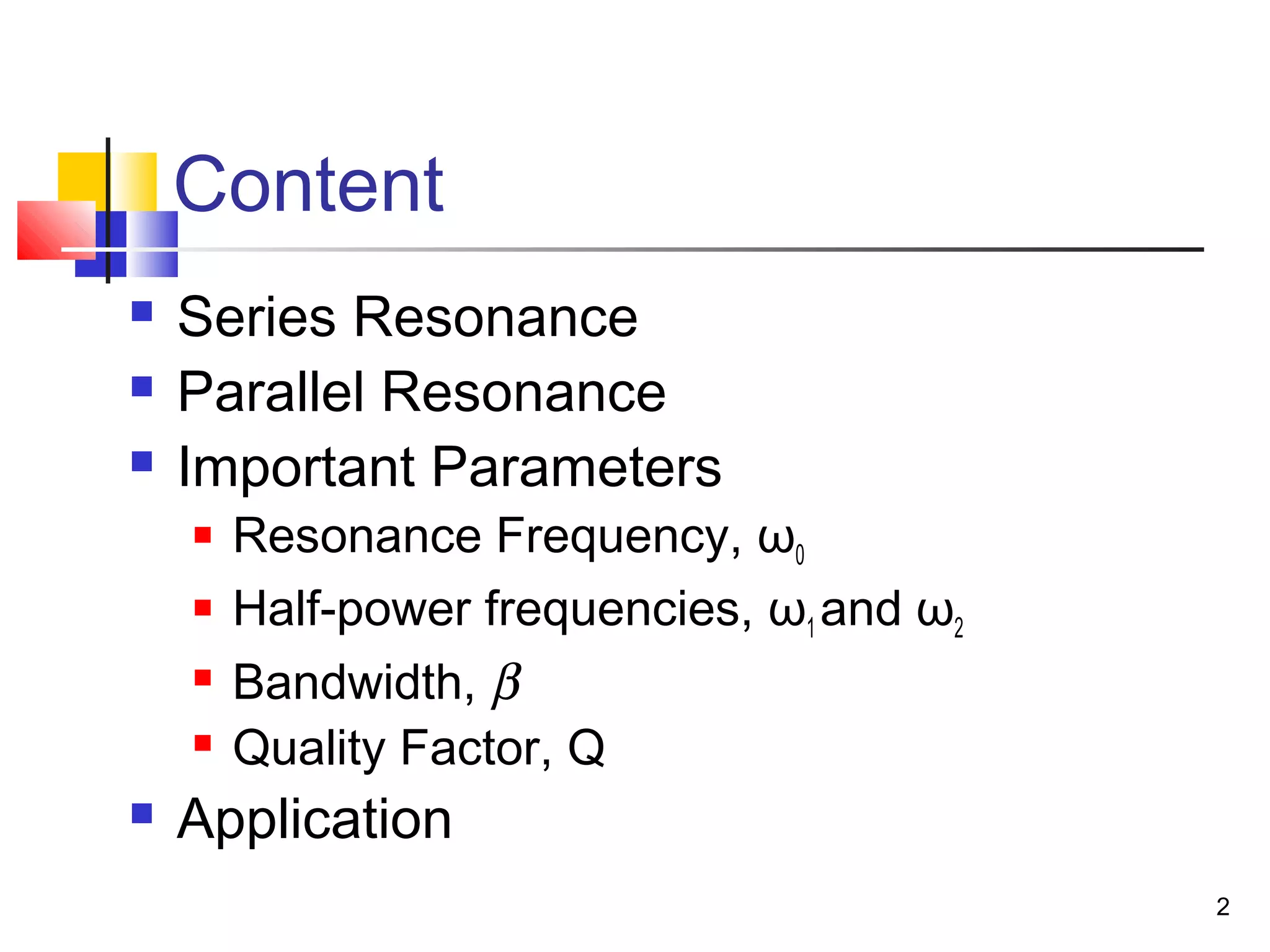
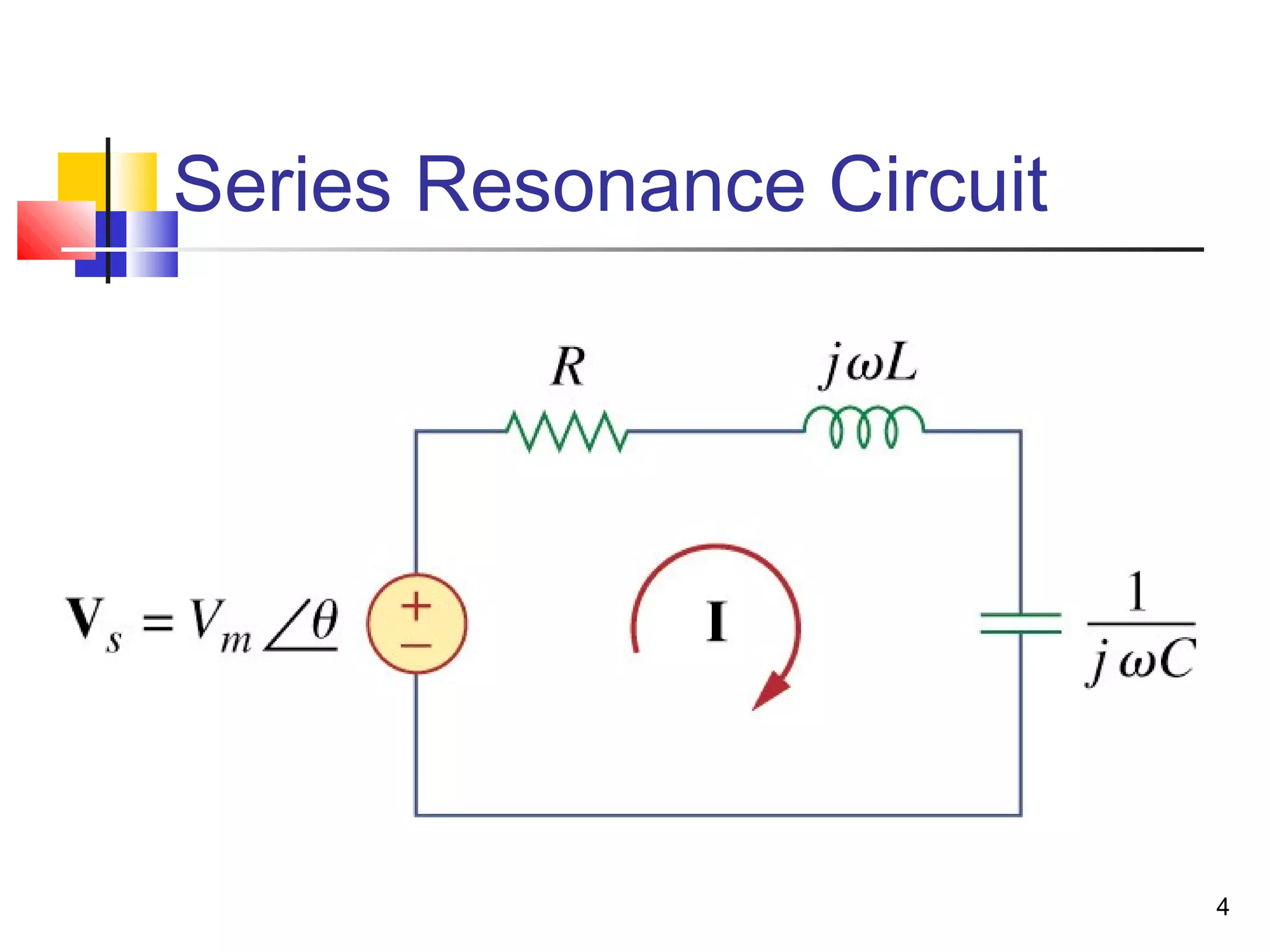
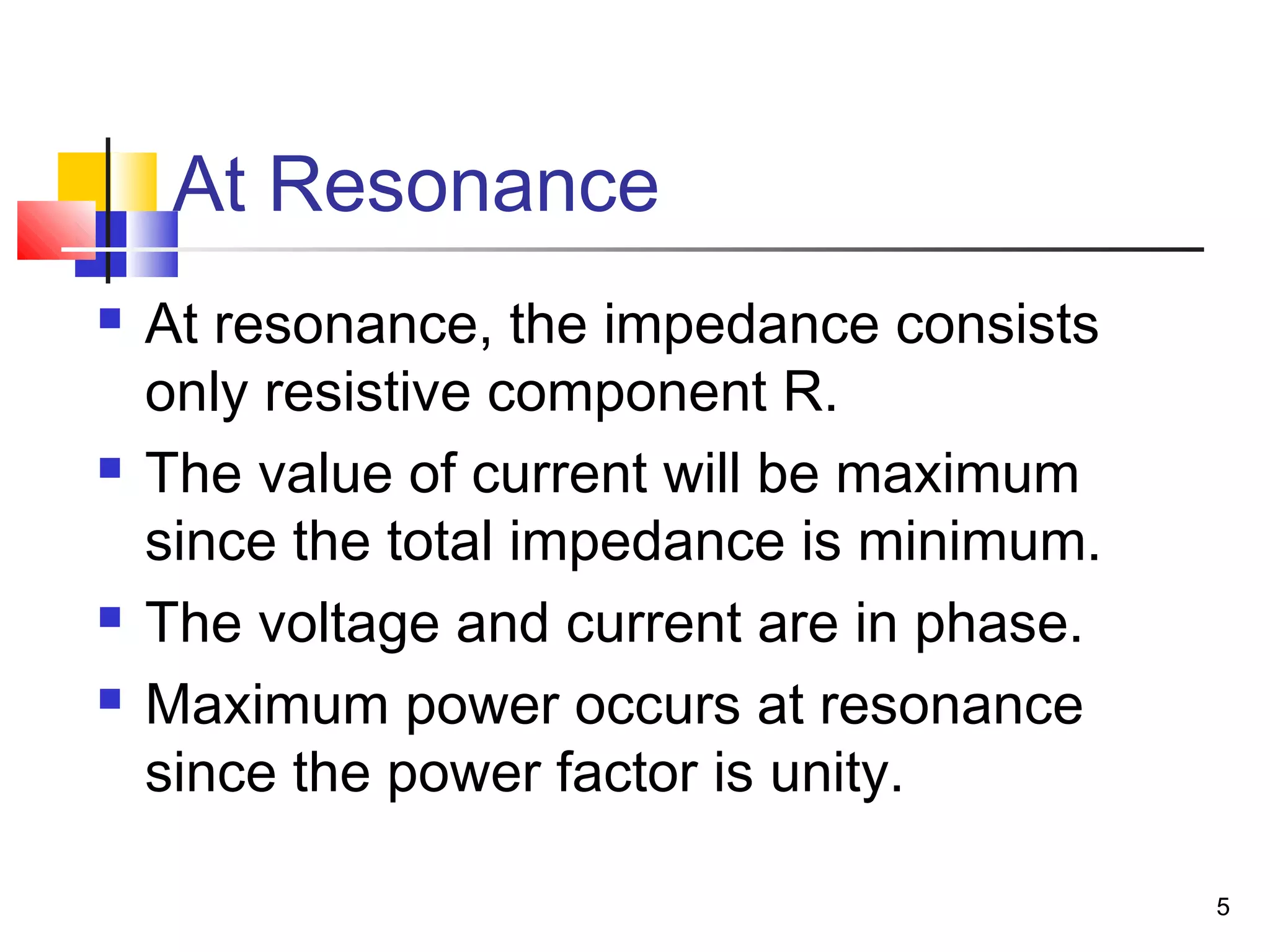
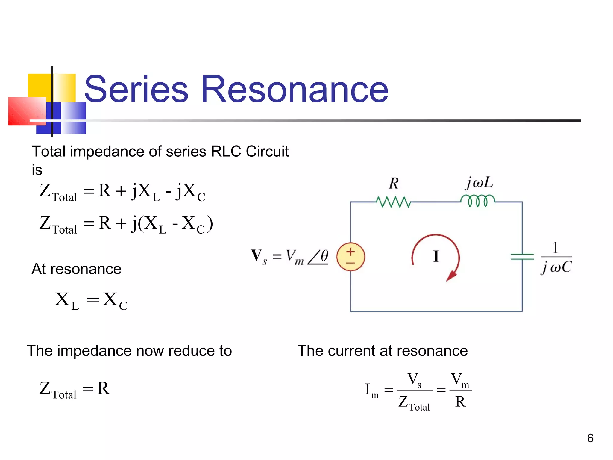
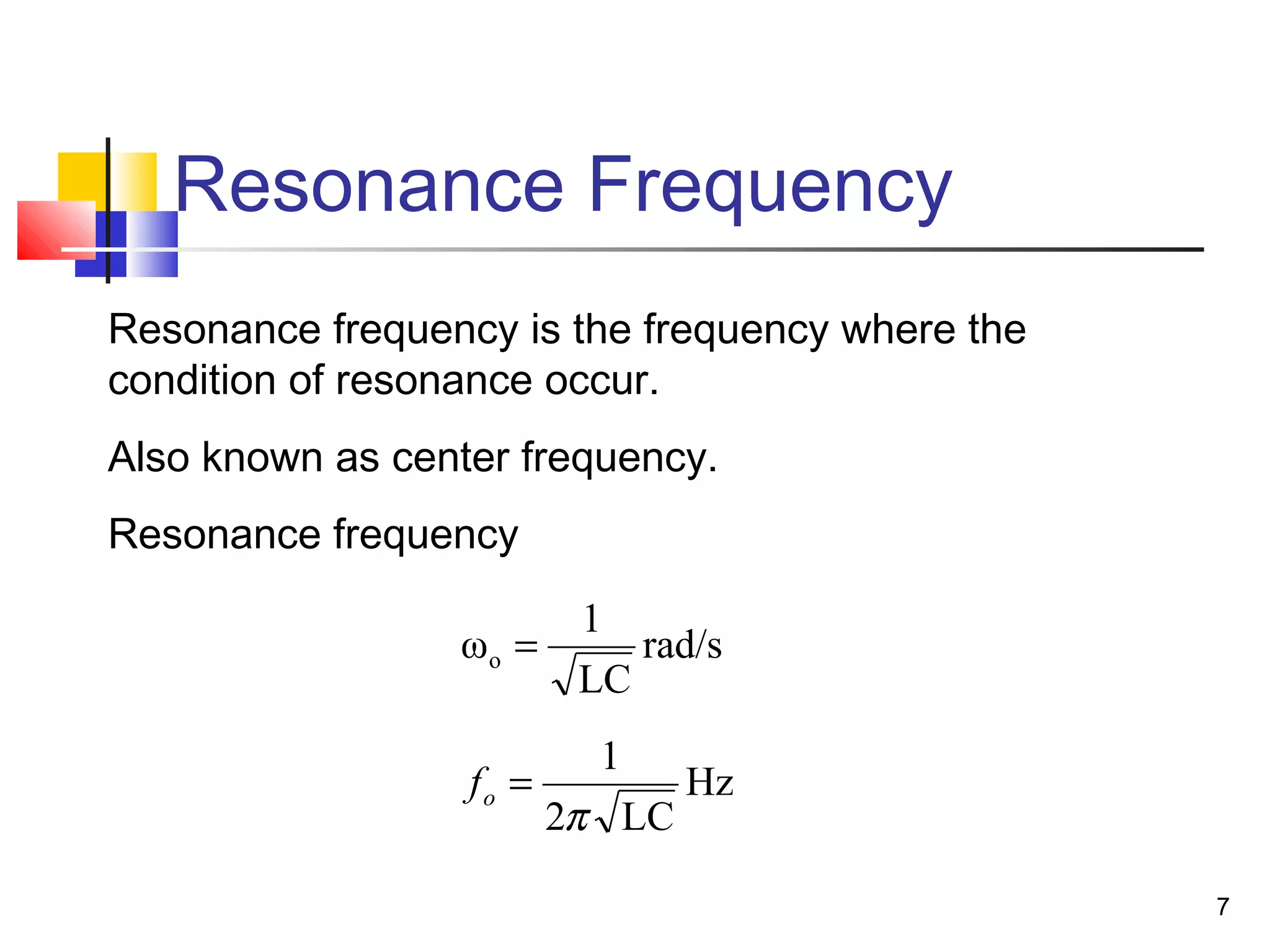
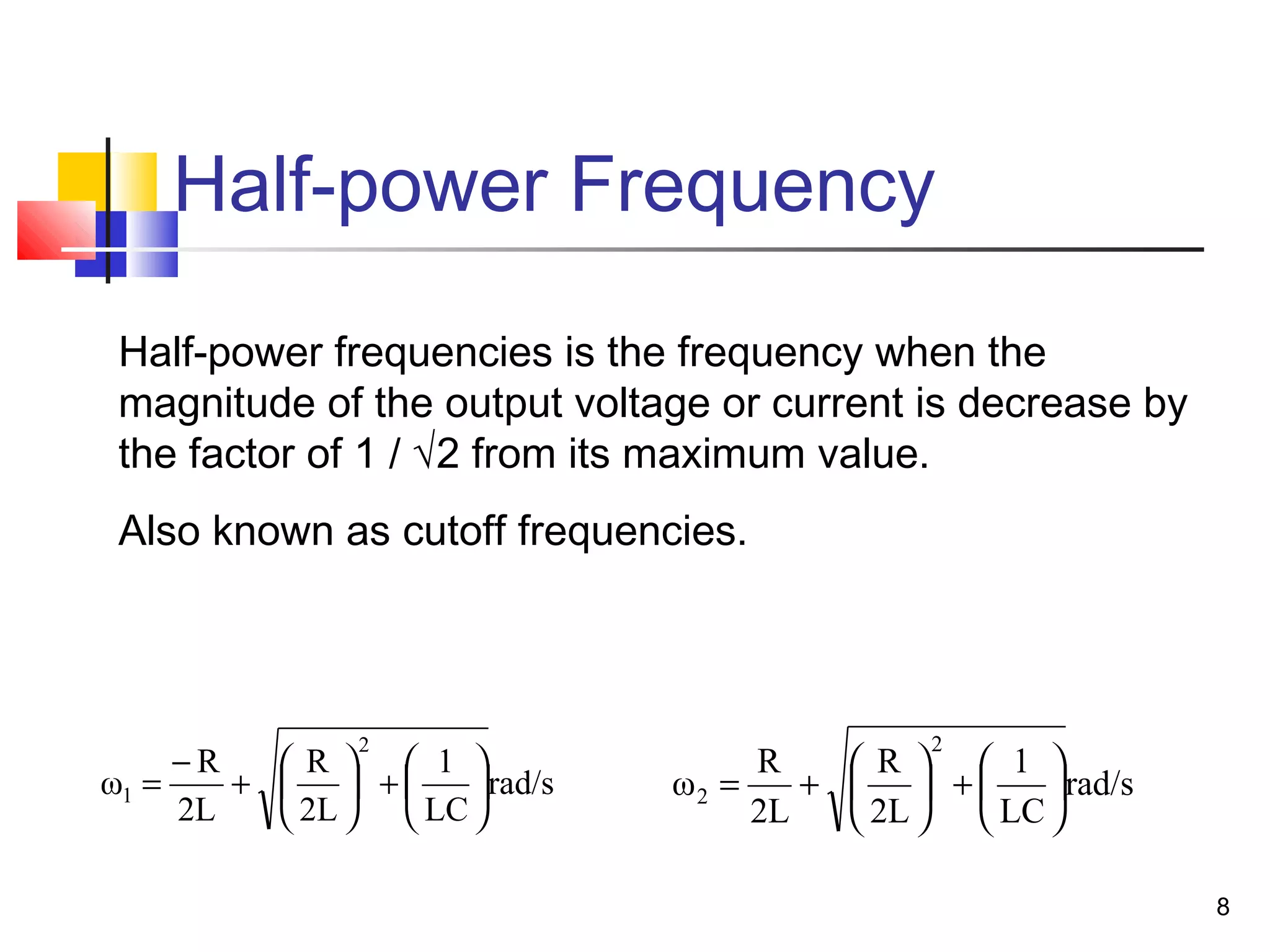
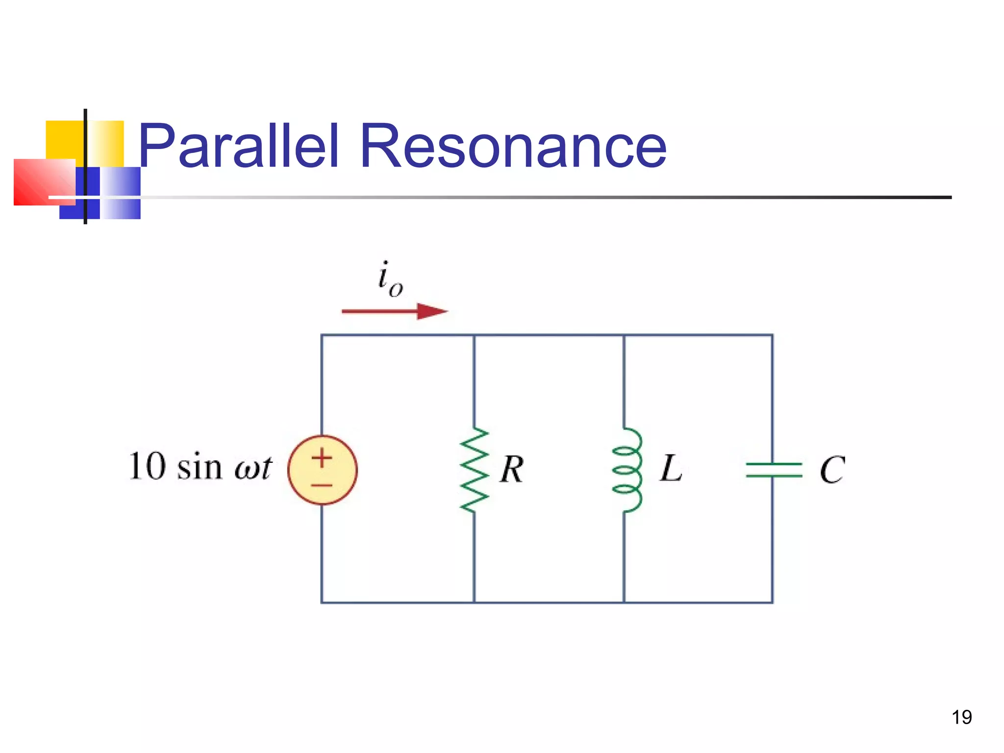
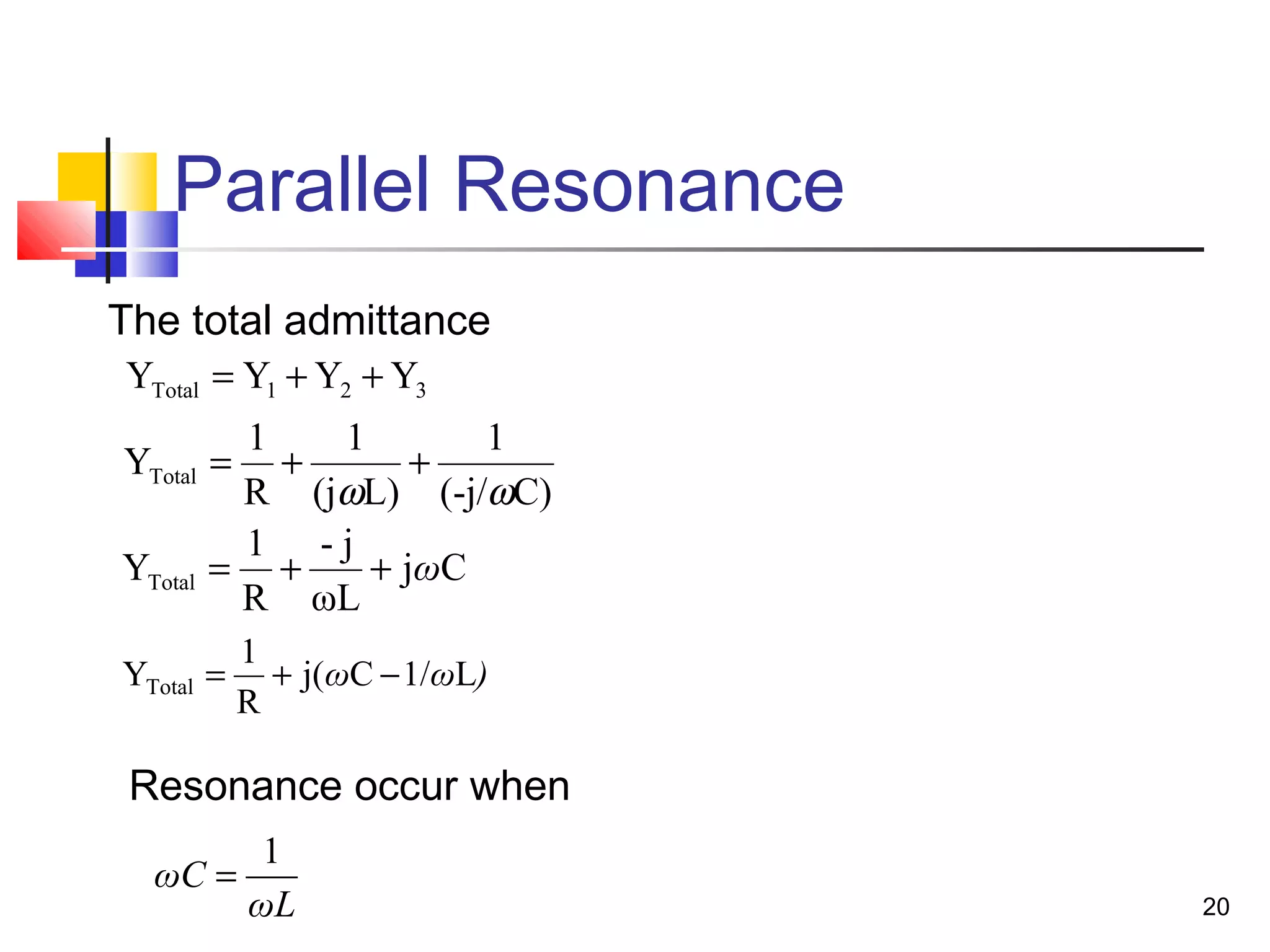
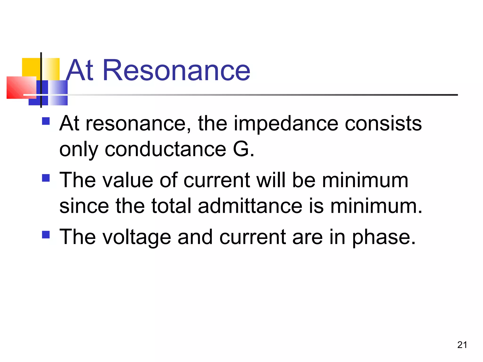
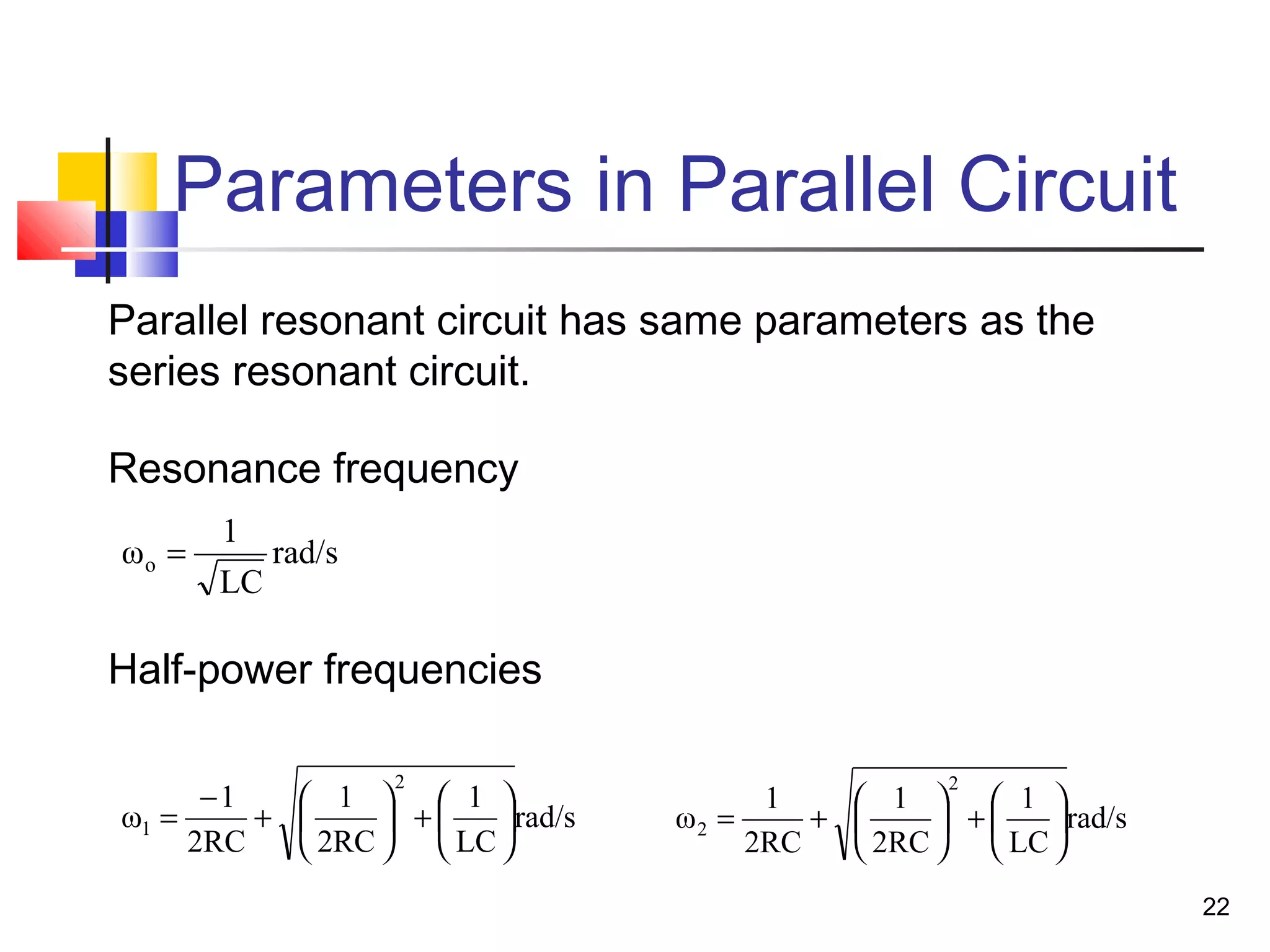
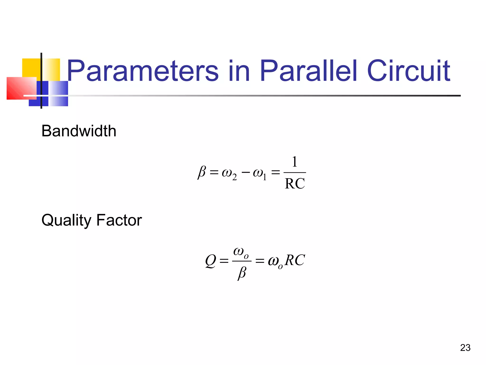
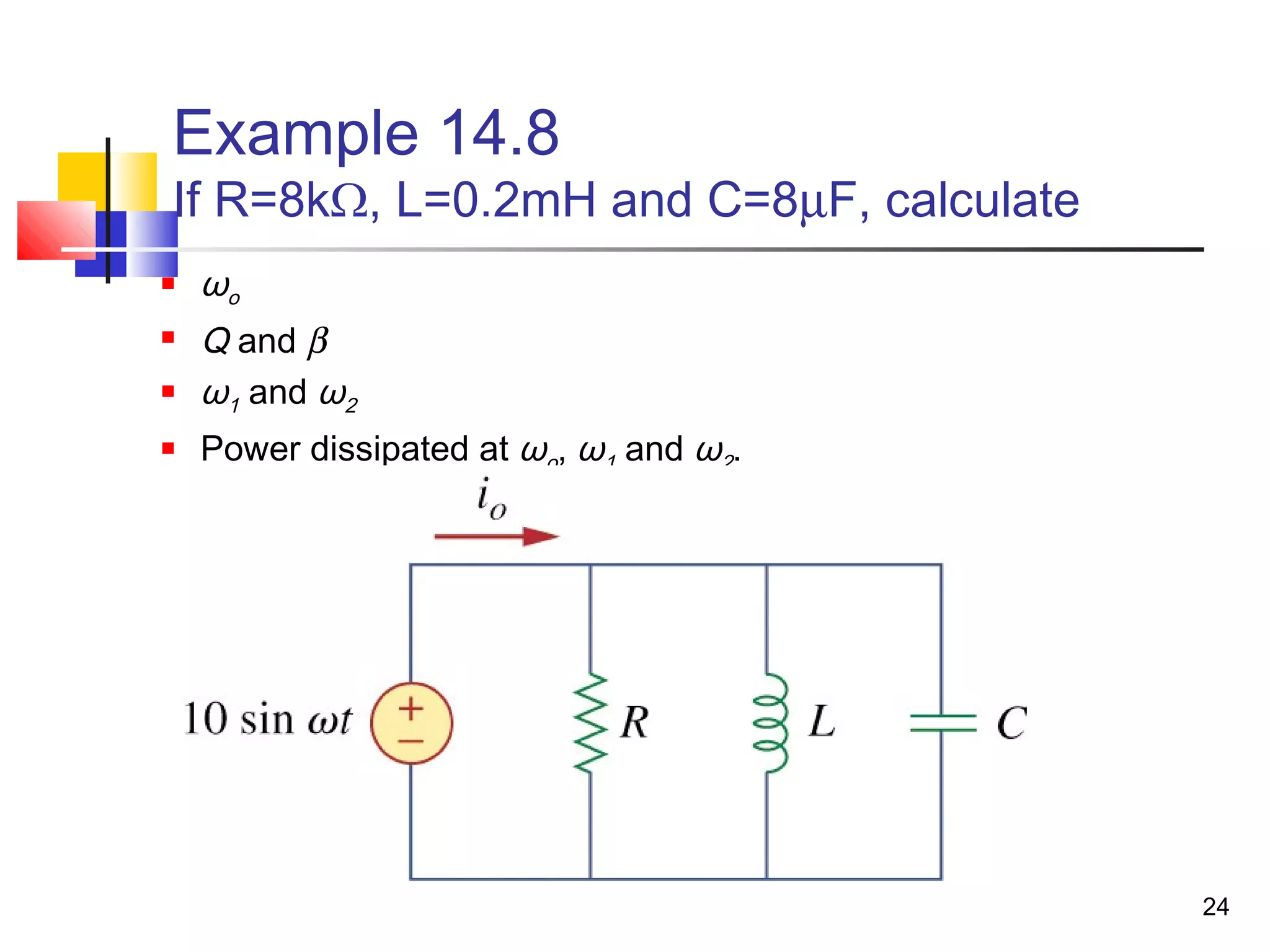
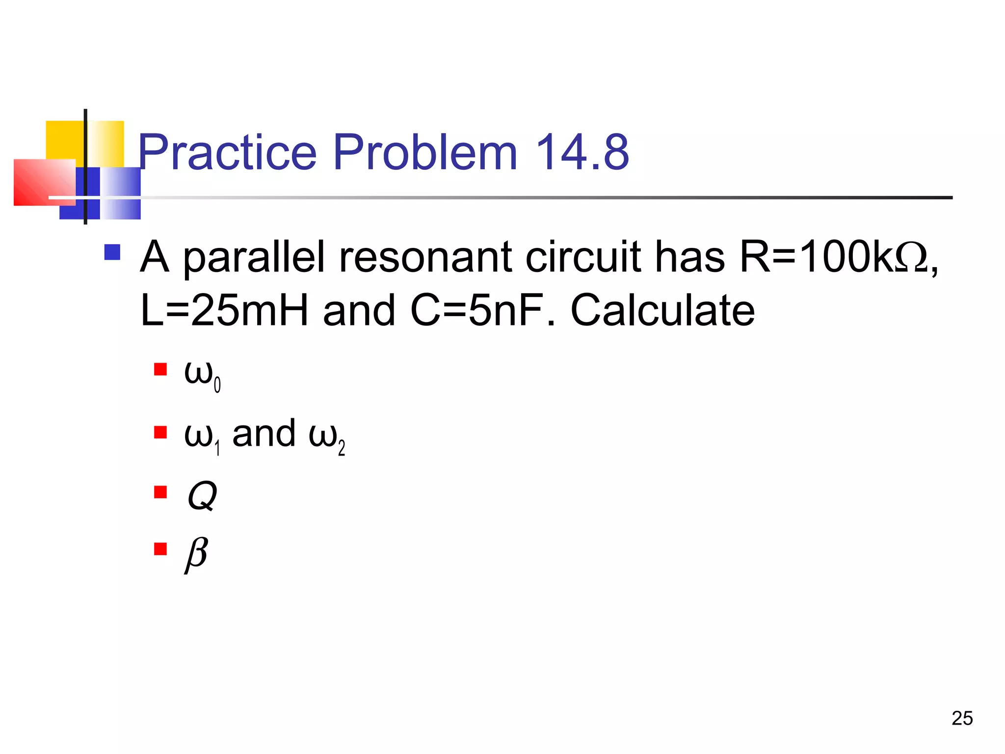

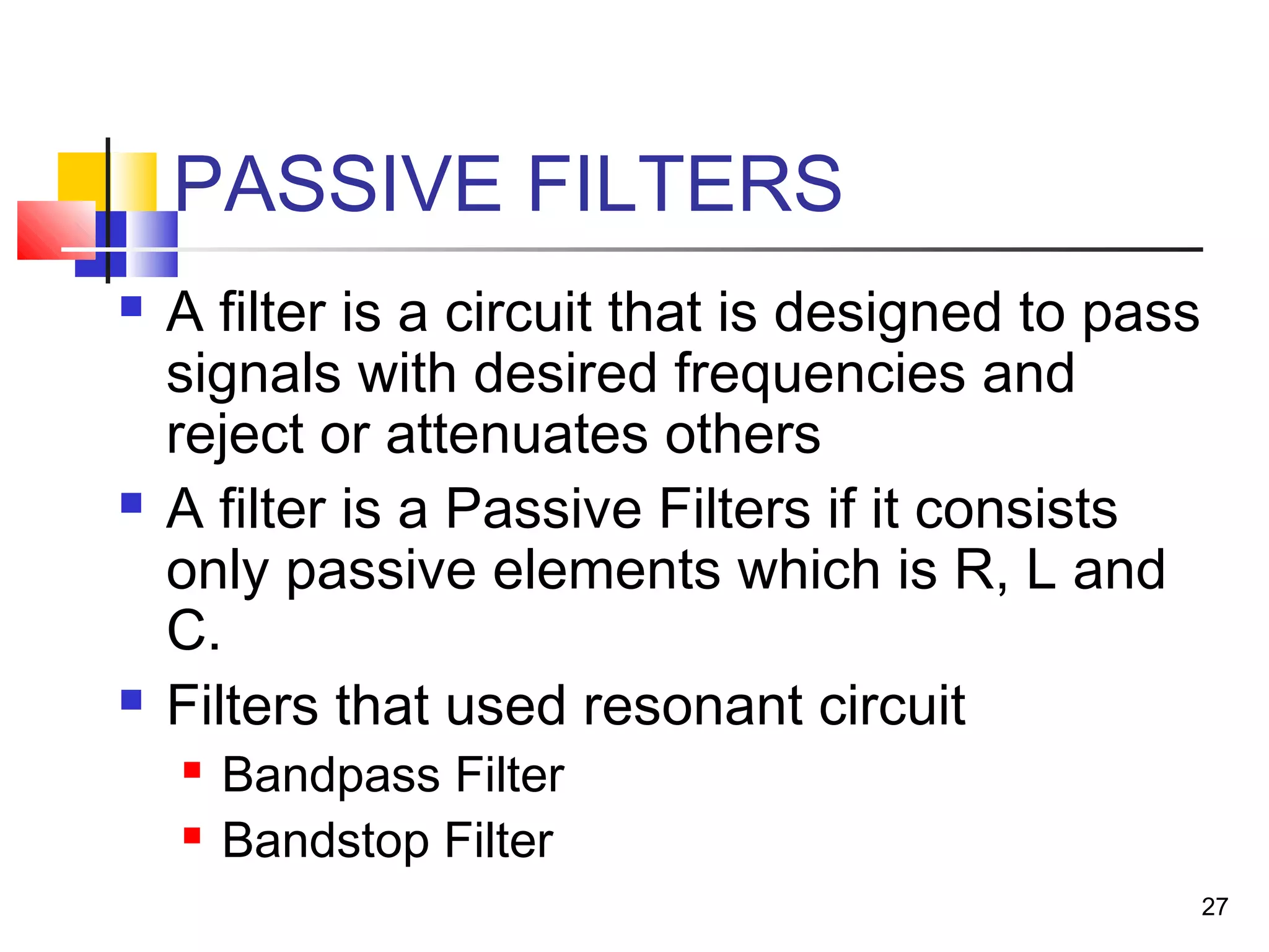
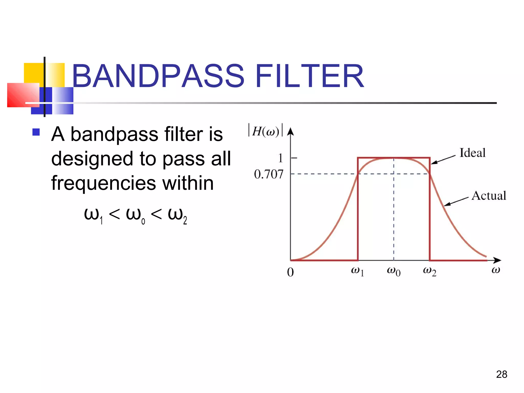
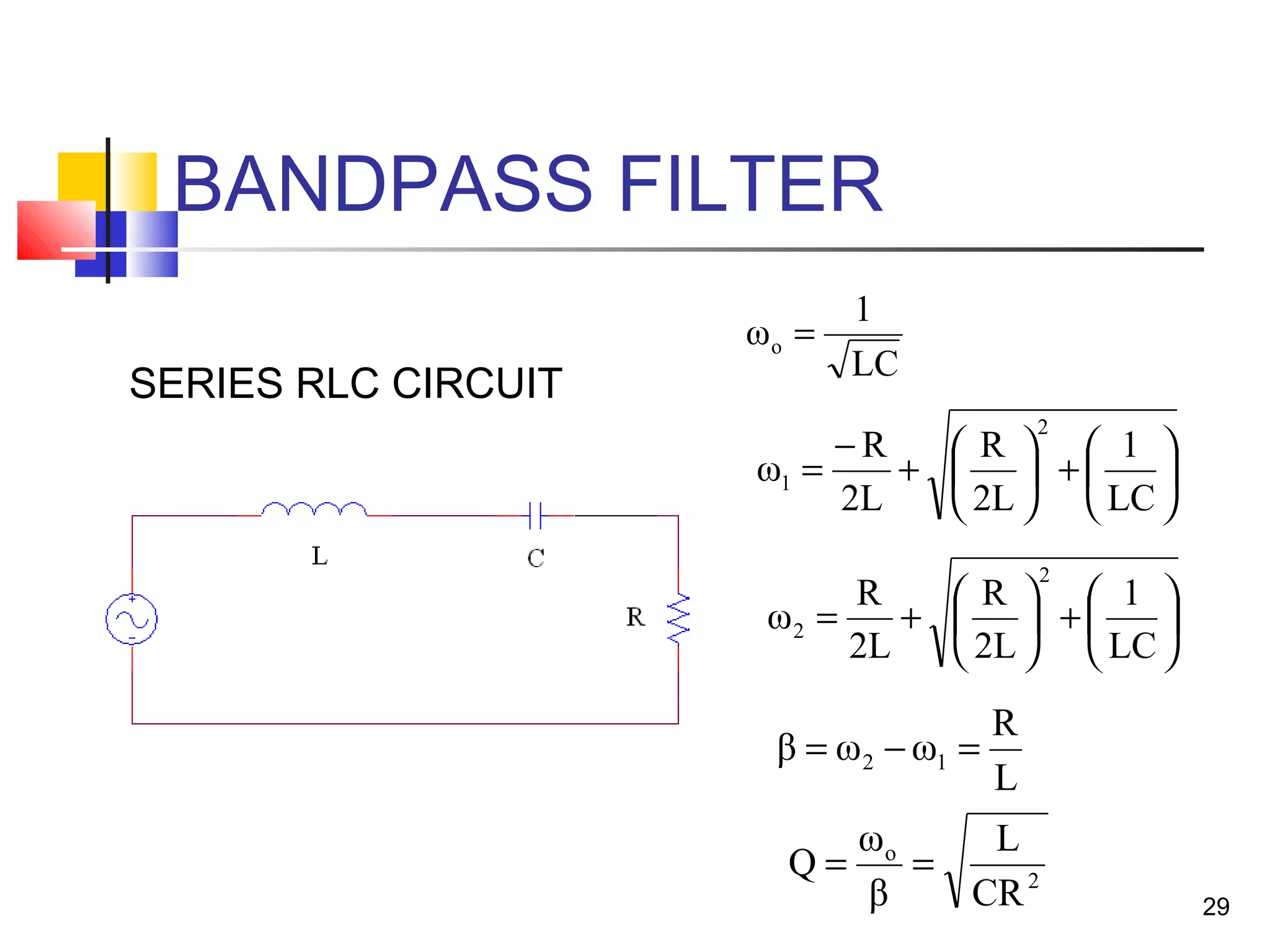
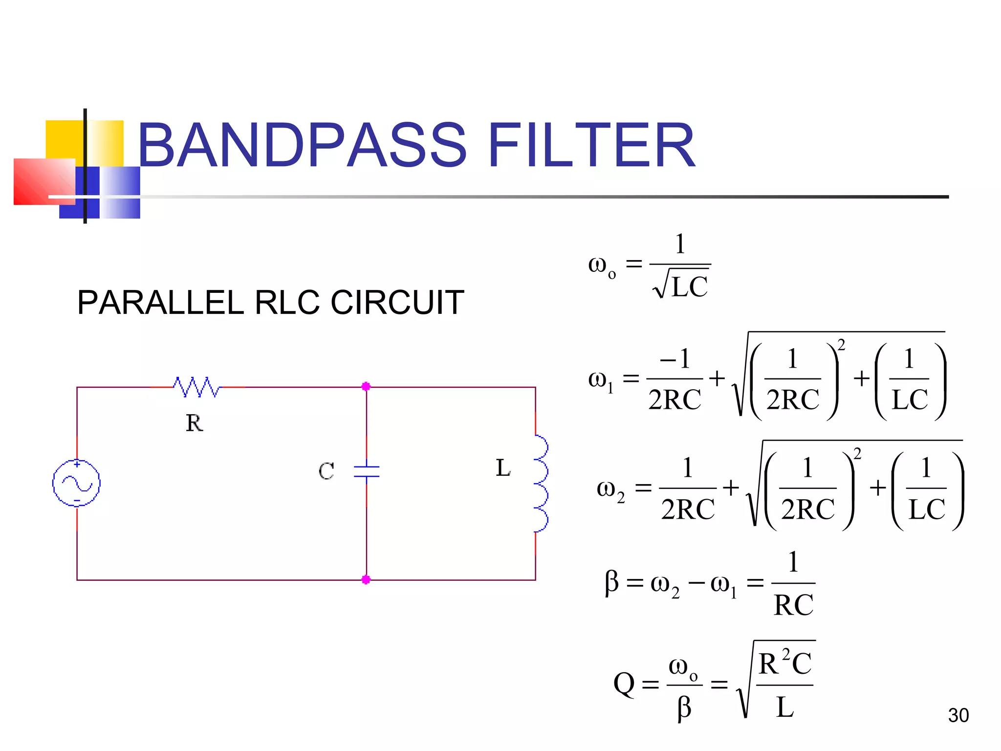
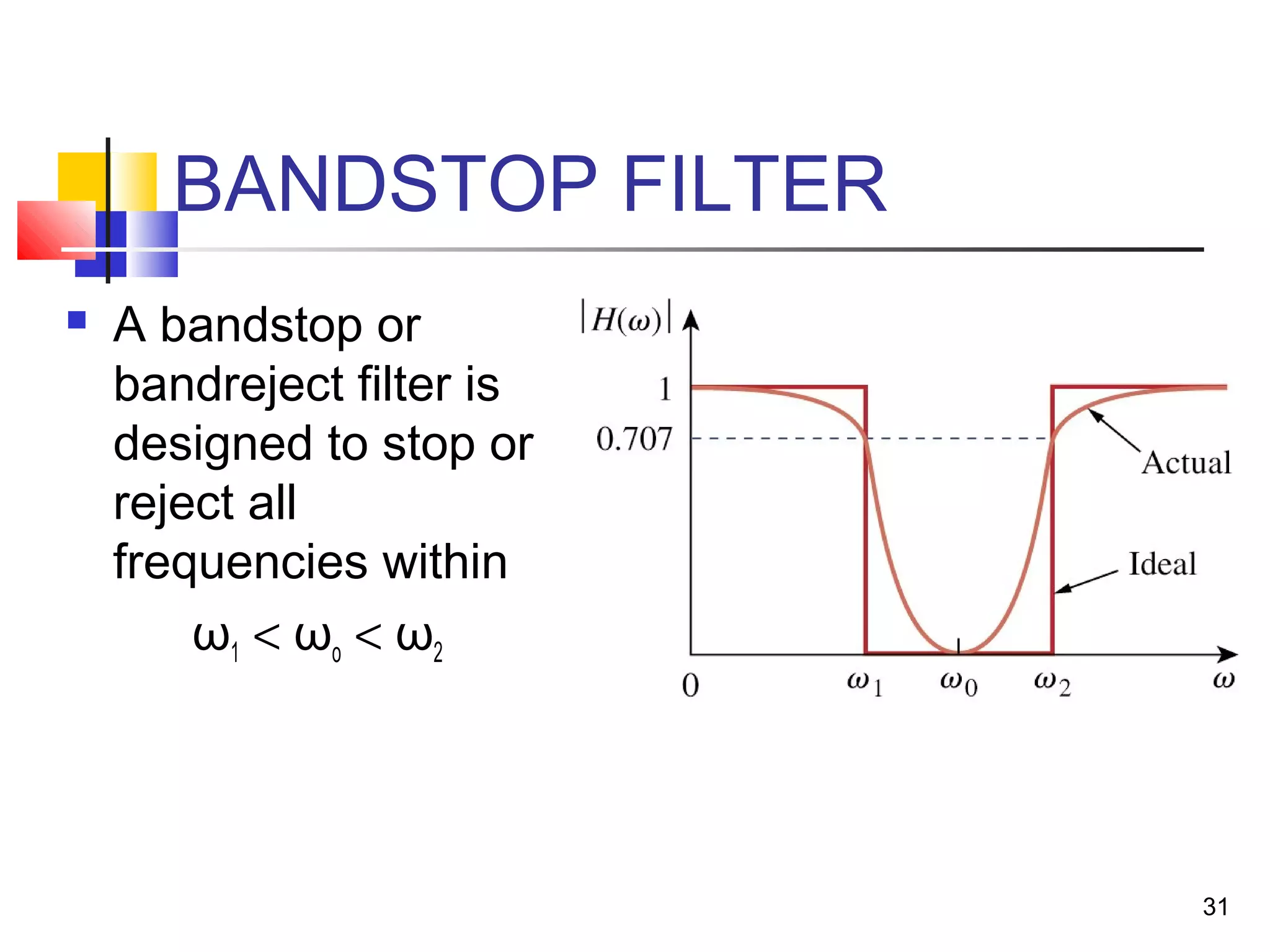
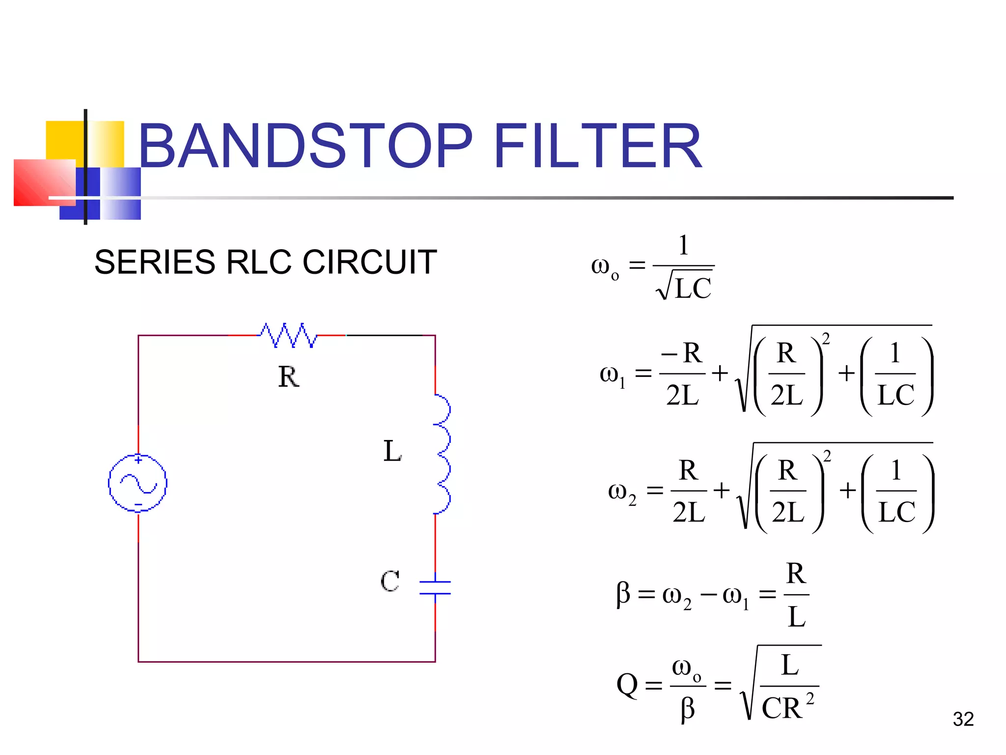
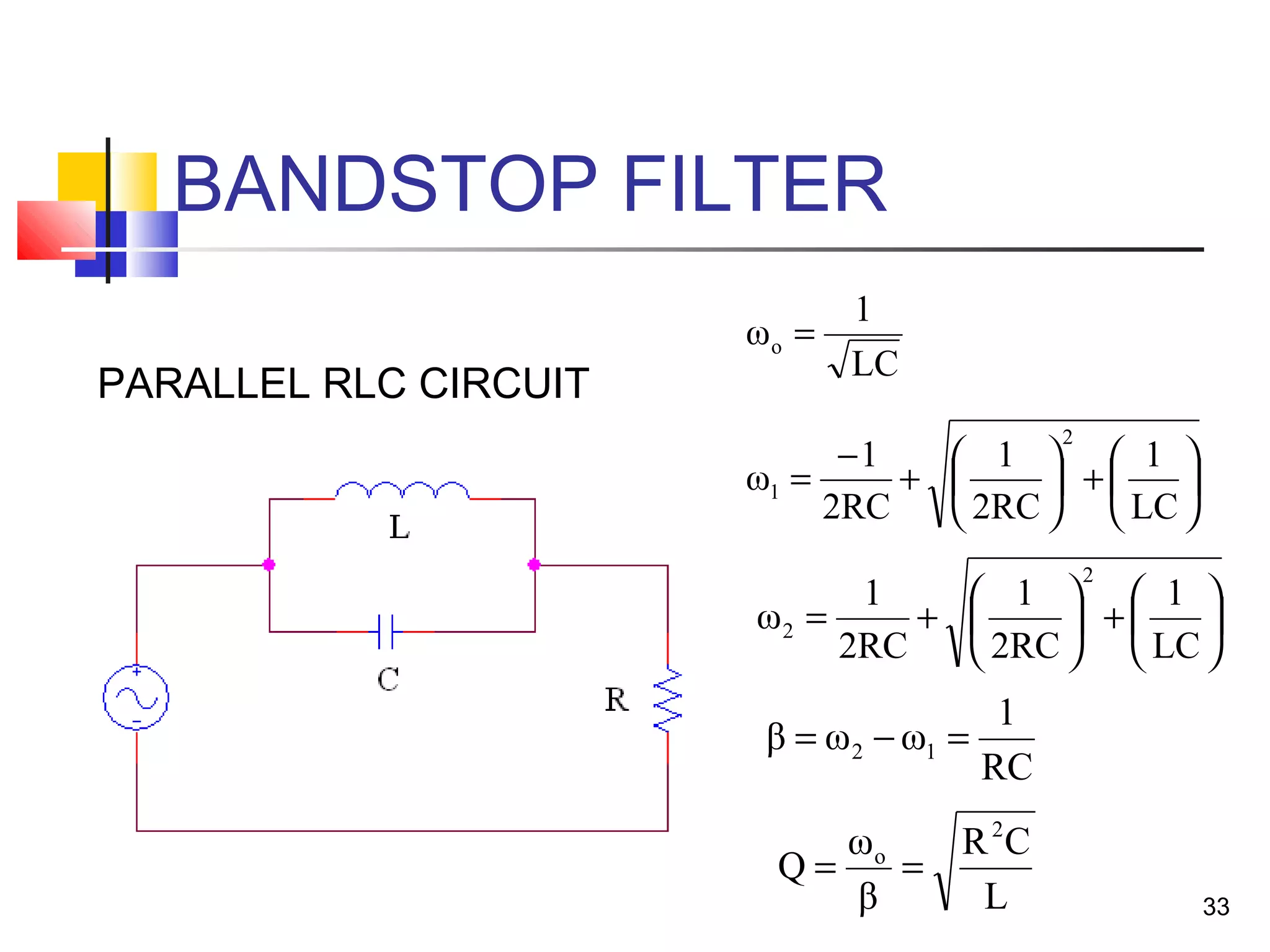

This document discusses resonance circuits and their applications. Resonance occurs when the capacitive and inductive reactances are equal, resulting in a purely resistive impedance. Key parameters of resonance circuits include the resonance frequency, half-power frequencies, bandwidth, and quality factor. Resonance circuits are useful for constructing filters and are used in applications like bandpass and bandstop filters, which allow only certain frequency ranges to pass.


