Download as PDF, PPTX

![Transmission-Line Equations
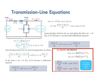
Kirchhoff Voltage Law:
Vin-Vout – VRʼ – VLʼ=0
Kirchhoff Current Law:
Iin – Iout – Icʼ – IGʼ=0
Note:
VL=L . di/dt
Ic=C . dv/dt
Remember:
2
2
|
|
;
tan
1
|
|
|
)
(
|
)
(
]
Im[
)
sin(
]
Re[
)
cos(
)
sin(
)
cos(
B
A
C
A
B
jB
A
C
e
e
z
E
z
E
Ae
A
Ae
A
Aj
A
Ae
j
j
j
j
j
z
+
=
=
→
+
=
=
=
=
=
+
=
θ
θ
θ
θ
θ
θ
θ
θ
θ
θ](https://image.slidesharecdn.com/transmissionlinespartii-221129094342-fcc97c13/85/TransmissionLinesPart_II-pdf-6-320.jpg)
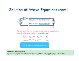
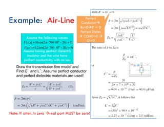
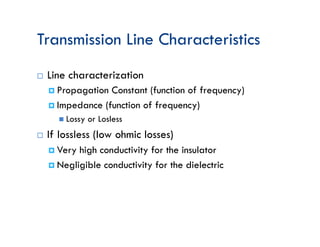
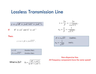
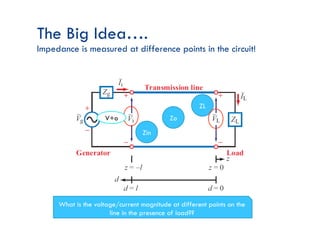
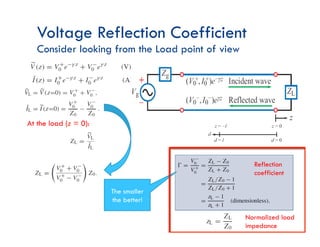
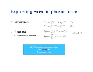
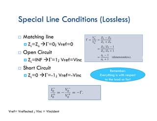
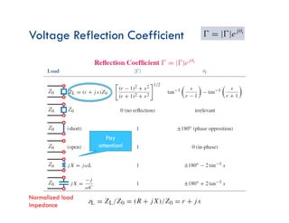
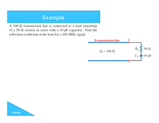
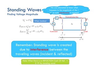
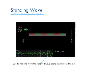
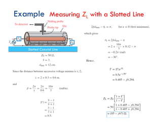
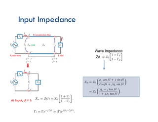
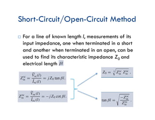
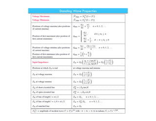
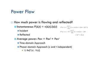
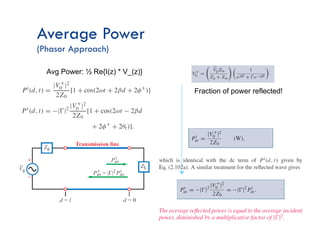
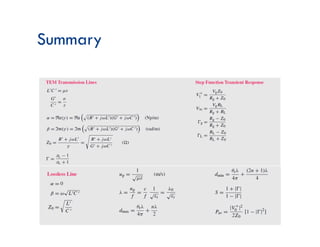
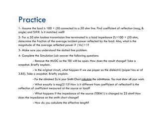

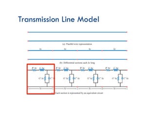
This document discusses transmission line theory and characteristics. It introduces the transmission line model and equations, including the telegrapher's equations. It covers lossless and lossy transmission lines, and derives the characteristic impedance. It also discusses voltage reflection coefficient, standing waves, and how to measure input impedance and determine characteristic impedance using open and short circuit methods. Power flow on transmission lines and the concept of average power is also introduced.


