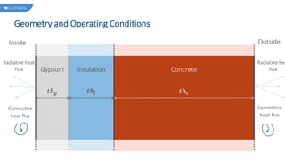
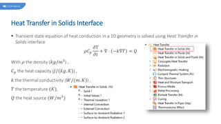
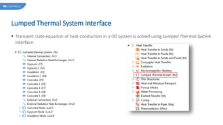
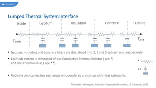
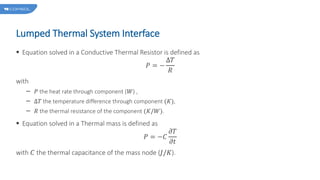
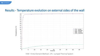
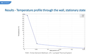
Transient conduction in a wall
Using Lumped Thermal System
Background and Motivation
 Tutorial model for using Lumped Thermal System components.
 A wall composed of gypsum, insulation and concrete layers exchange with outside and inside
ambient air through radiative and convective heat exchanges. The wall is initially at the external
temperature 𝑇𝑒𝑥𝑡.
 Does a Lumped Thermal System can evaluate the evolution of temperature on the external sides of
this wall, as accurately as a 1D Finite Element Model ?
 Two models will be set up, a 1D Finite Element Model and a 0D Lumped Thermal System model,
and their respective results will be compared.
Geometry and Operating Conditions
Gypsum
𝑡ℎ𝑔
Insulation
𝑡ℎ𝑖
Concrete
𝑡ℎ𝑐
Inside Outside
Radiative heat
flux
Convective
heat flux
Radiative hea
flux
Convective
heat flux
Heat Transfer in Solids Interface
 Transient state equation of heat conduction in a 1D geometry is solved using Heat Transfer in
Solids interface
𝜌𝐶𝑝
𝜕T
𝜕𝑡
+ ∇ ⋅ −𝑘∇𝑇 = 𝑄
With 𝜌 the density (𝑘𝑔/𝑚3
) ,
𝐶𝑝 the heat capacity (𝐽/(𝑘𝑔. 𝐾)) ,
𝑘 the thermal conductivity (𝑊/(𝑚. 𝐾)) ,
𝑇 the temperature (𝐾),
𝑄 the heat source (𝑊/𝑚3)
Lumped Thermal System Interface
 Transient state equation of heat conduction in a 0D system is solved using Lumped Thermal System
interface.
Lumped Thermal System Interface
 Gypsum, insulating and concrete layers are discretized into 2, 2 and 5 sub-systems, respectively.
 Each sub-system is composed of one Conductive Thermal Resistor ( see *)
and one Thermal Mass ( see **)
 Radiative and convective exchanges on boundaries are set up with Heat rate nodes.
Inside Gypsum Insulation Concrete
𝑇𝑎𝑚𝑏
Outside
𝑇𝑒𝑥𝑡
Transferts thermiques, Initiation et approfondissement, J.F. Sacadura, 2015
*
**
Lumped Thermal System Interface
 Equation solved in a Conductive Thermal Resistor is defined as
𝑃 = −
Δ𝑇
𝑅
with
𝑃 the heat rate through component (𝑊) ,
Δ𝑇 the temperature difference through component (𝐾),
𝑅 the thermal resistance of the component (𝐾/𝑊).
 Equation solved in a Thermal mass is defined as
𝑃 = −𝐶
𝜕𝑇
𝜕𝑡
with 𝐶 the thermal capacitance of the mass node (𝐽/𝐾).
Results - Temperature evolution on external sides of the wall
FEM : Finite Element Method ; LTS : Lumped Thermal System
Results - Temperature profile through the wall, stationary state
FEM : Finite Element Method ; LTS : Lumped Thermal System
Conclusion
 A 1D transient thermal conduction problem has been solved with Lumped Thermal System
interface.
 LTS results match the FEM resolution results if the lumped model is sufficiently refined by
discretized each wall layer into several sub-systems with their own mass and thermal resistance.
In this model, 5 sub-systems are used in the concrete layer and 2 in the gypsum and insulation
layers.

transient_conduction_in_a_wall.pptx

  • 1.
    Transient conduction ina wall Using Lumped Thermal System
  • 2.
    Background and Motivation Tutorial model for using Lumped Thermal System components.  A wall composed of gypsum, insulation and concrete layers exchange with outside and inside ambient air through radiative and convective heat exchanges. The wall is initially at the external temperature 𝑇𝑒𝑥𝑡.  Does a Lumped Thermal System can evaluate the evolution of temperature on the external sides of this wall, as accurately as a 1D Finite Element Model ?  Two models will be set up, a 1D Finite Element Model and a 0D Lumped Thermal System model, and their respective results will be compared.
  • 3.
    Geometry and OperatingConditions Gypsum 𝑡ℎ𝑔 Insulation 𝑡ℎ𝑖 Concrete 𝑡ℎ𝑐 Inside Outside Radiative heat flux Convective heat flux Radiative hea flux Convective heat flux
  • 4.
    Heat Transfer inSolids Interface  Transient state equation of heat conduction in a 1D geometry is solved using Heat Transfer in Solids interface 𝜌𝐶𝑝 𝜕T 𝜕𝑡 + ∇ ⋅ −𝑘∇𝑇 = 𝑄 With 𝜌 the density (𝑘𝑔/𝑚3 ) , 𝐶𝑝 the heat capacity (𝐽/(𝑘𝑔. 𝐾)) , 𝑘 the thermal conductivity (𝑊/(𝑚. 𝐾)) , 𝑇 the temperature (𝐾), 𝑄 the heat source (𝑊/𝑚3)
  • 5.
    Lumped Thermal SystemInterface  Transient state equation of heat conduction in a 0D system is solved using Lumped Thermal System interface.
  • 6.
    Lumped Thermal SystemInterface  Gypsum, insulating and concrete layers are discretized into 2, 2 and 5 sub-systems, respectively.  Each sub-system is composed of one Conductive Thermal Resistor ( see *) and one Thermal Mass ( see **)  Radiative and convective exchanges on boundaries are set up with Heat rate nodes. Inside Gypsum Insulation Concrete 𝑇𝑎𝑚𝑏 Outside 𝑇𝑒𝑥𝑡 Transferts thermiques, Initiation et approfondissement, J.F. Sacadura, 2015 * **
  • 7.
    Lumped Thermal SystemInterface  Equation solved in a Conductive Thermal Resistor is defined as 𝑃 = − Δ𝑇 𝑅 with 𝑃 the heat rate through component (𝑊) , Δ𝑇 the temperature difference through component (𝐾), 𝑅 the thermal resistance of the component (𝐾/𝑊).  Equation solved in a Thermal mass is defined as 𝑃 = −𝐶 𝜕𝑇 𝜕𝑡 with 𝐶 the thermal capacitance of the mass node (𝐽/𝐾).
  • 8.
    Results - Temperatureevolution on external sides of the wall FEM : Finite Element Method ; LTS : Lumped Thermal System
  • 9.
    Results - Temperatureprofile through the wall, stationary state FEM : Finite Element Method ; LTS : Lumped Thermal System
  • 10.
    Conclusion  A 1Dtransient thermal conduction problem has been solved with Lumped Thermal System interface.  LTS results match the FEM resolution results if the lumped model is sufficiently refined by discretized each wall layer into several sub-systems with their own mass and thermal resistance. In this model, 5 sub-systems are used in the concrete layer and 2 in the gypsum and insulation layers.

Editor's Notes

  • #2 You can use the heading from the application documentation for the title.