Download to read offline
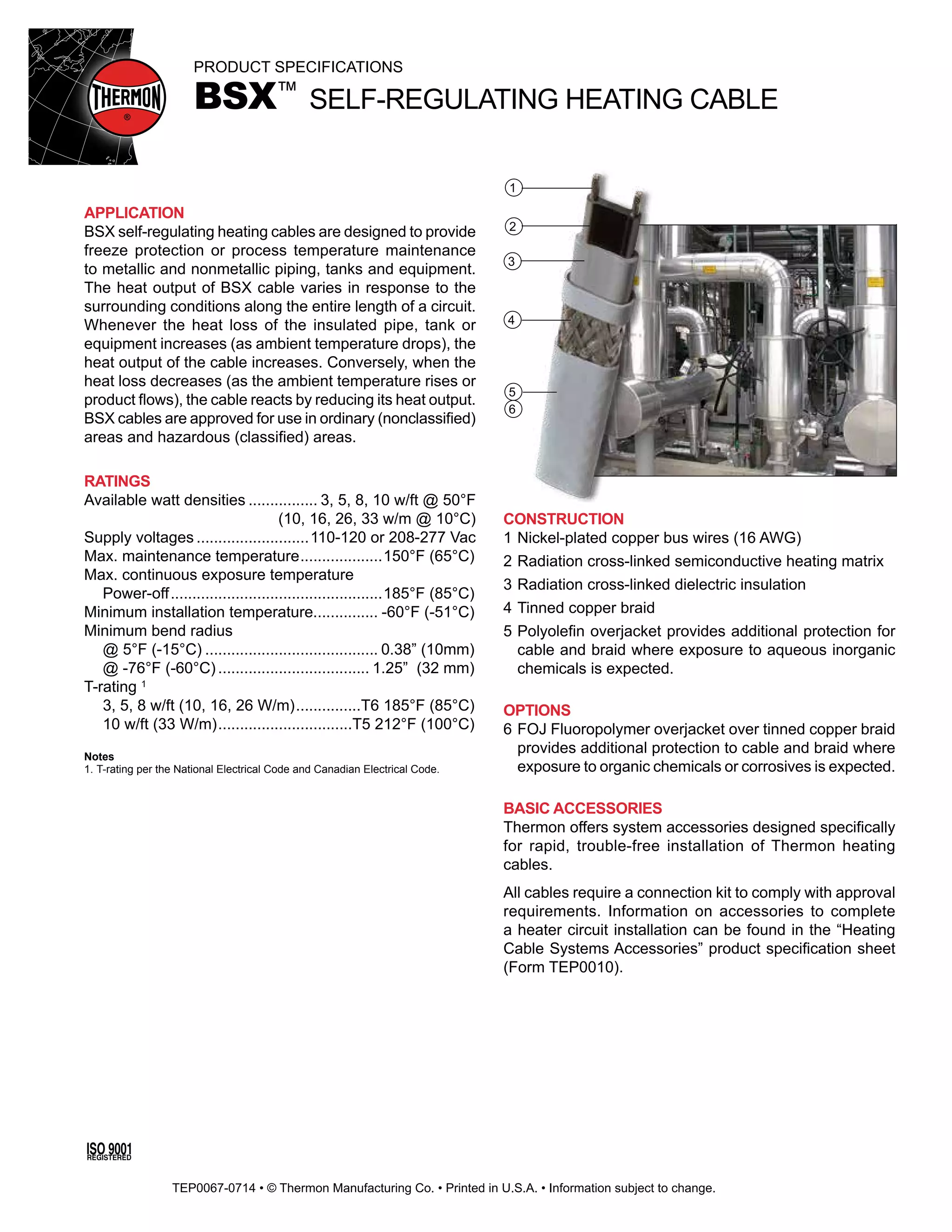


The document provides product specifications for Thermon's BSX self-regulating heating cable. The cable consists of nickel-plated copper bus wires, a semiconductive heating matrix, dielectric insulation, and a protective overjacket. It is designed to provide freeze protection or temperature maintenance for pipes, tanks, and equipment. The cable's heat output varies in response to surrounding conditions along its entire length. It is approved for use in ordinary and hazardous areas.


