Boiler
A steam boileris a device used to create steam by applying heat energy to water, typically under pressure, for use in
heating, power generation, or industrial applications.
Classification of Boilers
Boilers can be classified based on different criteria such as working pressure, fuel type, design, and application. Below
are the major classifications:
1. Based on Tube Content:
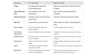
Fire-Tube Boiler: Hot gases pass through tubes surrounded by water (e.g., Lancashire, Cochran, Locomotive boilers).
Water-Tube Boiler: Water flows inside tubes, heated externally by fire (e.g., Babcock & Wilcox, Lamont, Benson
boilers).
2. Based on Boiler Pressure:
• Low-Pressure Boiler: Operates at a pressure below 15 psi (e.g., Cochran boiler).
• Medium-Pressure Boiler: Operates between 15 to 80 psi (e.g., Lancashire boiler).
• High-Pressure Boiler: Operates above 80 psi (e.g., Benson, LaMont, Loeffler boilers).
3.
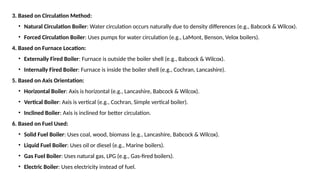
3. Based onCirculation Method:
• Natural Circulation Boiler: Water circulation occurs naturally due to density differences (e.g., Babcock & Wilcox).
• Forced Circulation Boiler: Uses pumps for water circulation (e.g., LaMont, Benson, Velox boilers).
4. Based on Furnace Location:
• Externally Fired Boiler: Furnace is outside the boiler shell (e.g., Babcock & Wilcox).
• Internally Fired Boiler: Furnace is inside the boiler shell (e.g., Cochran, Lancashire).
5. Based on Axis Orientation:
• Horizontal Boiler: Axis is horizontal (e.g., Lancashire, Babcock & Wilcox).
• Vertical Boiler: Axis is vertical (e.g., Cochran, Simple vertical boiler).
• Inclined Boiler: Axis is inclined for better circulation.
6. Based on Fuel Used:
• Solid Fuel Boiler: Uses coal, wood, biomass (e.g., Lancashire, Babcock & Wilcox).
• Liquid Fuel Boiler: Uses oil or diesel (e.g., Marine boilers).
• Gas Fuel Boiler: Uses natural gas, LPG (e.g., Gas-fired boilers).
• Electric Boiler: Uses electricity instead of fuel.
4.
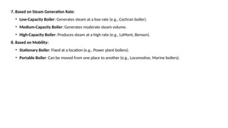
7. Based onSteam Generation Rate:
• Low-Capacity Boiler: Generates steam at a low rate (e.g., Cochran boiler).
• Medium-Capacity Boiler: Generates moderate steam volume.
• High-Capacity Boiler: Produces steam at a high rate (e.g., LaMont, Benson).
8. Based on Mobility:
• Stationary Boiler: Fixed at a location (e.g., Power plant boilers).
• Portable Boiler: Can be moved from one place to another (e.g., Locomotive, Marine boilers).
6.
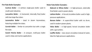
Fire-Tube Boiler Examples:
CochranBoiler – A vertical, single-pass boiler used in
small-scale industries.
Lancashire Boiler – A horizontal, internally fired boiler
with two large flue tubes.
Locomotive Boiler – Used in steam locomotives,
featuring multiple fire tubes.
Cornish Boiler – Similar to Lancashire but with a single
fire tube.
Scotch Marine Boiler – A compact, multi-pass boiler
used in ships and marine applications
Water-Tube Boiler Examples:
Babcock & Wilcox Boiler – A high-pressure, externally
fired boiler used in power plants.
LaMont Boiler – A forced circulation boiler used in high-
pressure applications.
Benson Boiler – A supercritical boiler with no drum,
used in modern power plants.
Velox Boiler – A high-speed, forced circulation boiler
with a gas turbine.
Loeffler Boiler – Uses steam circulation instead of water,
ideal for high-pressure applications.
7.
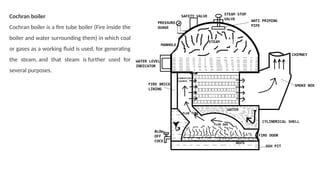
Cochran boiler
Cochran boileris a fire tube boiler (Fire inside the
boiler and water surrounding them) in which coal
or gases as a working fluid is used, for generating
the steam, and that steam is further used for
several purposes.
8.
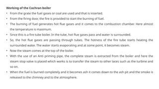
Working of theCochran boiler
• From the grate the fuel gases or coal are used and that is inserted.
• From the firing door, the fire is provided to start the burning of fuel.
• The burning of fuel generates hot flue gases and it comes to the combustion chamber. Here almost
the temperature is maximum.
• Since this is a fire tube boiler. In the tube, hot flue gases pass and water is surrounded.
• So, the hot flue gases are passing through tubes. The hotness of the fire tube starts heating the
surrounded water. The water starts evaporating and at some point, it becomes steam.
• Now the steam comes at the top of the boiler.
• With the use of an Anti priming pipe, the complete steam is extracted from the boiler and here the
steam stop valve is placed which works is to transfer the steam to other laces such as the turbine and
so on.
• When the fuel is burned completely and it becomes ash it comes down to the ash pit and the smoke is
released to the chimney and to the atmosphere.
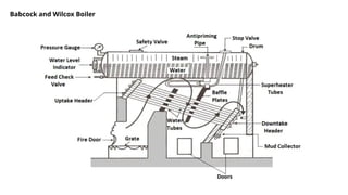
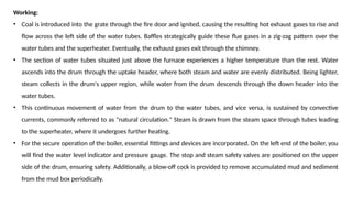
Working:
• Coal isintroduced into the grate through the fire door and ignited, causing the resulting hot exhaust gases to rise and
flow across the left side of the water tubes. Baffles strategically guide these flue gases in a zig-zag pattern over the
water tubes and the superheater. Eventually, the exhaust gases exit through the chimney.
• The section of water tubes situated just above the furnace experiences a higher temperature than the rest. Water
ascends into the drum through the uptake header, where both steam and water are evenly distributed. Being lighter,
steam collects in the drum's upper region, while water from the drum descends through the down header into the
water tubes.
• This continuous movement of water from the drum to the water tubes, and vice versa, is sustained by convective
currents, commonly referred to as "natural circulation." Steam is drawn from the steam space through tubes leading
to the superheater, where it undergoes further heating.
• For the secure operation of the boiler, essential fittings and devices are incorporated. On the left end of the boiler, you
will find the water level indicator and pressure gauge. The stop and steam safety valves are positioned on the upper
side of the drum, ensuring safety. Additionally, a blow-off cock is provided to remove accumulated mud and sediment
from the mud box periodically.
11.
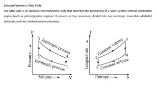
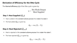
Constant Volume orOtto Cycle
The Otto cycle is an idealized thermodynamic cycle that describes the functioning of a spark-ignition internal combustion
engine (such as petrol/gasoline engines). It consists of four processes, divided into two isentropic (reversible adiabatic)
processes and two constant-volume processes.
12.
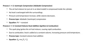
Process 1 →2: Isentropic Compression (Adiabatic Compression)
• The air-fuel mixture (or just air in an ideal model) is compressed inside the cylinder.
• No heat is exchanged with the surroundings.
• Pressure and temperature increase, while volume decreases.
• Process type: Adiabatic (isentropic) compression
• Equation: PV γ
=constant
Process 2 → 3: Constant-Volume Heat Addition (Ignition & Combustion)
• The spark plug ignites the air-fuel mixture, causing rapid combustion.
• Due to combustion, heat is added at a constant volume, increasing pressure and temperature.
• Process type: Constant-volume heat addition
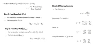
• Equation: Qin=mcv(T3−T2)
13.
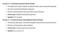
Process 3 →4: Isentropic Expansion (Power Stroke)
• The high-pressure gases expand, pushing the piston down and performing work.
• No heat is transferred (adiabatic expansion).
• Pressure and temperature decrease while volume increases.
• Process type: Adiabatic (isentropic) expansion
• Equation: PVγ
=constant
Process 4 → 1: Constant-Volume Heat Rejection (Exhaust Stroke)
• The exhaust valve opens, and the burned gases release heat at constant volume.
• Pressure and temperature drop suddenly.
• Process type: Constant-volume heat rejection
• Equation: Q out=mcv(T4−T1)
16.
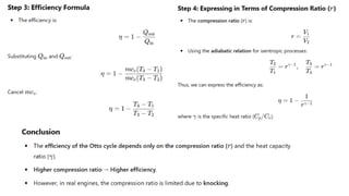
Diesel Cycle
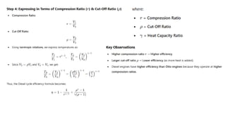
The DieselCycle is a thermodynamic cycle that models the working of compression-ignition (CI) engines, commonly
found in diesel engines. Unlike the Otto Cycle (where heat is added at constant volume), the Diesel cycle adds heat at
constant pressure.
17.
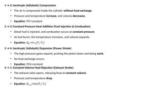
1 → 2:Isentropic (Adiabatic) Compression
• The air is compressed inside the cylinder without heat exchange.
• Pressure and temperature increase, and volume decreases.
• Equation: PVγ
=constant
2 → 3: Constant-Pressure Heat Addition (Fuel Injection & Combustion)
• Diesel fuel is injected, and combustion occurs at constant pressure.
• As fuel burns, the temperature increases, and volume expands.
• Equation: Qin=m cp(T3−T2)
3 → 4: Isentropic (Adiabatic) Expansion (Power Stroke)
• The high-pressure gases expand, pushing the piston down and doing work.
• No heat exchange occurs.
• Equation: PVγ=constant
4 → 1: Constant-Volume Heat Rejection (Exhaust Stroke)
• The exhaust valve opens, releasing heat at constant volume.
• Pressure and temperature drop.
• Equation: Q out=mcv(T4−T1)
20.
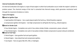
Internal Combustion (IC)Engine
An Internal Combustion (IC) Engine is a type of heat engine in which fuel combustion occurs inside the engine's cylinder to
produce power. The chemical energy of the fuel is converted into thermal energy, which generates mechanical work
through the movement of pistons or rotors.
Types of IC Engines
Based on Ignition Type
1️
1️
⃣
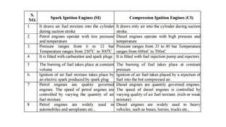
1. Spark Ignition (SI) Engines – Use a spark plug to ignite the fuel (e.g., Petrol/Gasoline engines).
2. Compression Ignition (CI) Engines – Use high compression to self-ignite the fuel (e.g., Diesel engines).
Based on Stroke Cycle
2️
⃣
3. Four-Stroke Engine – Completes one cycle in four piston strokes (intake, compression, power, exhaust).
4. Two-Stroke Engine – Completes one cycle in two piston strokes (intake-compression & power-exhaust combined).
Based on Fuel Type
3️
3️
⃣
5. Petrol Engine – Uses gasoline fuel and spark ignition.
6. Diesel Engine – Uses diesel fuel and compression ignition.
7. Gas Engine – Runs on gases like LPG, CNG, or hydrogen.
21.
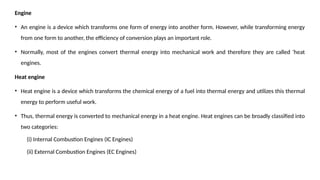
Engine
• An engineis a device which transforms one form of energy into another form. However, while transforming energy
from one form to another, the efficiency of conversion plays an important role.
• Normally, most of the engines convert thermal energy into mechanical work and therefore they are called ‘heat
engines.
Heat engine
• Heat engine is a device which transforms the chemical energy of a fuel into thermal energy and utilizes this thermal
energy to perform useful work.
• Thus, thermal energy is converted to mechanical energy in a heat engine. Heat engines can be broadly classified into
two categories:
(i) Internal Combustion Engines (IC Engines)
(ii) External Combustion Engines (EC Engines)
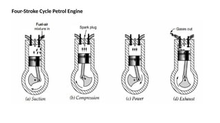
Suction Stroke
• Thesuction valve opens, exhaust valve remains closed as shown in Figure.
• The piston moves from the top dead centre to the bottom dead centre, the charge (mixture of fuel and air prepared in
the carburettor) is drawn into the cylinder.
Compression Stroke
• When the piston moves from the bottom dead centre to top dead centre, and the suction valve is closed, exhaust valve
remains closed as shown in Figure.
• The trapped charge in the cylinder is compressed by the upward moving piston. As the piston approaches the top dead
centre, the compression stroke completes.
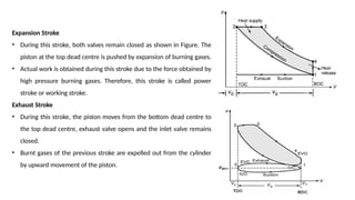
Expansion Stroke
• At the end of the compression stroke, the compressed charge is ignited by a high intensity spark created by a spark plug,
combustion starts and the high-pressure burning gases force the piston downward as shown in Figure.
• The gas pressure performs work, therefore, it is also called working stroke or power stroke. When the piston approaches
the bottom dead centre in its downward stroke then this stroke is completed.
• In this stroke, both valves remain closed.
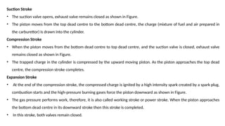
24.
Exhaust Stroke
• Whenthe piston moves from the bottom dead centre to the top dead centre, only the exhaust valve opens and
burnt gases are expelled to surroundings by upward movement of the piston as shown in Figure.
• This stroke is completed when the piston approaches the top dead centre. Thus, one cycle of a four-stroke petrol
engine is completed. The next cycle begins with piston movement from the top dead centre to the bottom dead
centre.
25.
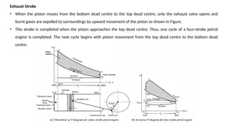
Four-stroke Diesel Engine
SuctionStroke
• The inlet (suction) valve opens, the exhaust valve remains closed, only air is
drawn into the cylinder as the piston moves from the top dead centre to the
bottom dead centre.
• This stroke ends as the piston approaches the bottom dead centre.
Compression Stroke
• As the piston moves from the bottom dead centre to the top dead centre, the
inlet valve closes, exhaust valve remains closed as shown in Figure.
• The air trapped into the cylinder is compressed in the cylinder till the piston
approaches the top dead centre. The air temperature reaches about 800°C by
compression.
• At the end of the compression stroke, the fuel is injected at very high pressure
into the compressed hot air. The temperature of hot compressed air is sufficient
to ignite the injected fuel. Thus, ignition takes place inside the cylinder.
26.
Expansion Stroke
• Duringthis stroke, both valves remain closed as shown in Figure. The
piston at the top dead centre is pushed by expansion of burning gases.
• Actual work is obtained during this stroke due to the force obtained by
high pressure burning gases. Therefore, this stroke is called power
stroke or working stroke.
Exhaust Stroke
• During this stroke, the piston moves from the bottom dead centre to
the top dead centre, exhaust valve opens and the inlet valve remains
closed.
• Burnt gases of the previous stroke are expelled out from the cylinder
by upward movement of the piston.
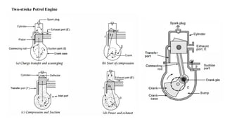
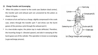
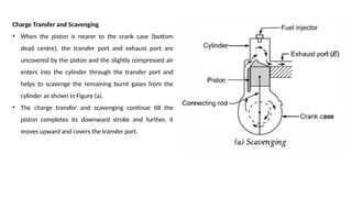
(i) Charge Transferand Scavenging
• When the piston is nearer to the crank case (bottom dead centre),
the transfer port and exhaust port are uncovered by the piston as
shown in Figure.
• A mixture of air and fuel as a charge, slightly compressed in the crank
case, enters through the transfer port T and drives out the burnt
gasses of the previous cycle through the exhaust port E.
• In a two-stroke engine, the piston top is made deflected. Therefore,
the incoming charge is directed upward, and aids in sweeping of the
burnt gases out of the cylinder. This operation is known as scavenging
(a gas-exchange process).
29.
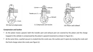
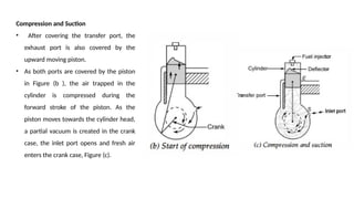
Compression and Suction
•As the piston moves upward, both the transfer port and exhaust port are covered by the piston and the charge
trapped in the cylinder is compressed by the piston's upward movement as shown in Figure (b ).
• At the same time, a partial vacuum is created into the crank case, the suction port S opens by moving the crank and
the fresh charge enters the crank case Figure (c).
30.
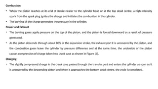
Combustion
• When thepiston reaches at its end of stroke nearer to the cylinder head or at the top dead centre, a high-intensity
spark from the spark plug ignites the charge and initiates the combustion in the cylinder.
• The burning of the charge generates the pressure in the cylinder.
Power and Exhaust
• The burning gases apply pressure on the top of the piston, and the piston is forced downward as a result of pressure
generated.
• As the piston descends through about 80% of the expansion stroke, the exhaust port E is uncovered by the piston, and
the combustion gases leave the cylinder by pressure difference and at the same time, the underside of the piston
causes compression of charge taken into crank case as shown in Figure (d).
Charging
• The slightly compressed charge in the crank case passes through the transfer port and enters the cylinder as soon as it
is uncovered by the descending piston and when it approaches the bottom dead centre, the cycle is completed.
Charge Transfer andScavenging
• When the piston is nearer to the crank case (bottom
dead centre), the transfer port and exhaust port are
uncovered by the piston and the slightly compressed air
enters into the cylinder through the transfer port and
helps to scavenge the remaining burnt gases from the
cylinder as shown in Figure (a).
• The charge transfer and scavenging continue till the
piston completes its downward stroke and further, it
moves upward and covers the transfer port.
34.
Compression and Suction
•After covering the transfer port, the
exhaust port is also covered by the
upward moving piston.
• As both ports are covered by the piston
in Figure (b ), the air trapped in the
cylinder is compressed during the
forward stroke of the piston. As the
piston moves towards the cylinder head,
a partial vacuum is created in the crank
case, the inlet port opens and fresh air
enters the crank case, Figure (c).
35.
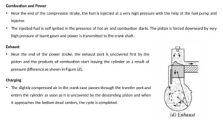
Combustion and Power
•Near the end of the compression stroke, the fuel is injected at a very high pressure with the help of the fuel pump and
injector.
• The injected fuel is self ignited in the presence of hot air and combustion starts. The piston is forced downward by very
high pressure of burnt gases and power is transmitted to the crank shaft.
Exhaust
• Near the end of the power stroke, the exhaust port is uncovered first by the
piston and the products of combustion start leaving the cylinder as a result of
pressure difference as shown in Figure (d).
Charging
• The slightly compressed air in the crank case passes through the transfer port and
enters the cylinder as soon as it is uncovered by the descending piston and when
it approaches the bottom dead centers, the cycle is completed.
36.
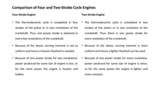
Comparison of Fourand Two-Stroke Cycle Engines
Four-Stroke Engine
• The thermodynamic cycle is completed in four
strokes of the piston or in two revolutions of the
crankshaft. Thus, one power stroke is obtained in
every two revolutions of the crankshaft.
• Because of the above, turning moment is not so
uniform and hence a heavier flywheel is needed.
• Because of one power stroke for two revolutions,
power produced for same size of engine is less, or
for the same power the engine is heavier and
bulkier.
Two-Stroke Engine
• The thermodynamic cycle is completed in two
strokes of the piston or in one revolution of the
crankshaft. Thus, there is one power stroke for
every revolution of the crankshaft.
• Because of the above, turning moment is more
uniform and hence a lighter flywheel can be used.
• Because of one power stroke for every revolution,
power produced for same size of engine is twice,
or for the same power the engine is lighter and
more compact.
37.
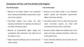
Comparison of Fourand Two-Stroke Cycle Engines
Four-Stroke Engine
• Because of one power stroke in two revolutions
lesser cooling and lubrication requirements. Lower
rate of wear and tear.
• Four-stroke engines have valves and valve
actuating mechanisms for opening and closing of
the intake and exhaust valves.
• Because of comparatively higher weight and
complicated valve mechanism, the initial cost of
the engine is more.
• Higher volumetric efficiency due to more time for
mixture intake.
Two-Stroke Engine
• Because of one power stroke in one revolution
greater cooling and lubrication requirements.
Higher rate of wear and tear.
• Two-stroke engines have no valves but only ports
(some two-stroke engines are fitted with
conventional exhaust valve or reed valve).
• Because of light weight and simplicity due to the
absence of valve actuating mechanism, initial cost
of the engine is less.
• Lower volumetric efficiency due to lesser time for
mixture intake.
38.
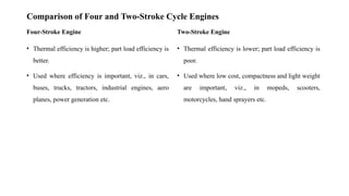
Comparison of Fourand Two-Stroke Cycle Engines
Four-Stroke Engine
• Thermal efficiency is higher; part load efficiency is
better.
• Used where efficiency is important, viz., in cars,
buses, trucks, tractors, industrial engines, aero
planes, power generation etc.
Two-Stroke Engine
• Thermal efficiency is lower; part load efficiency is
poor.
• Used where low cost, compactness and light weight
are important, viz., in mopeds, scooters,
motorcycles, hand sprayers etc.