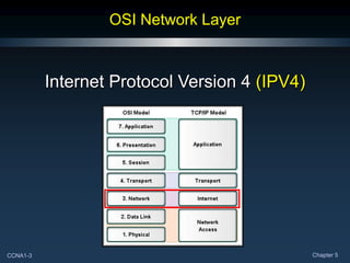
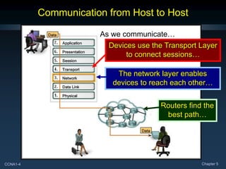
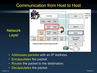
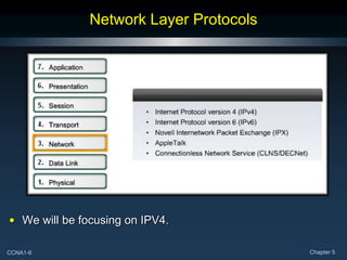
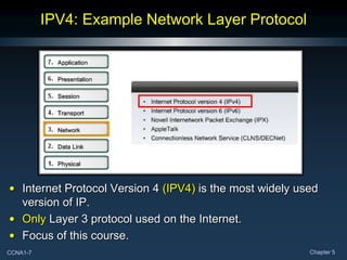
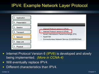
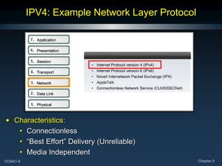
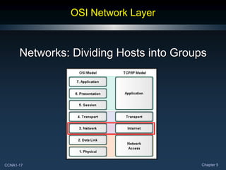
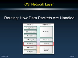
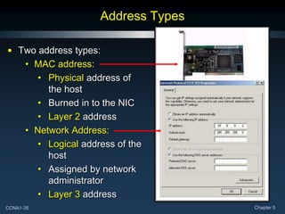
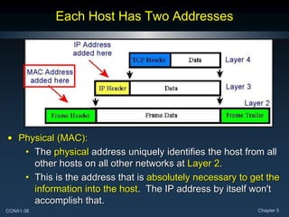
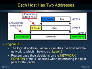
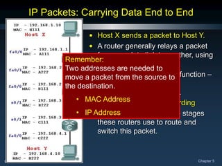
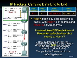
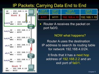
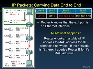
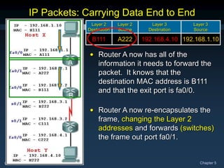
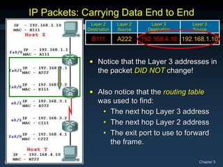
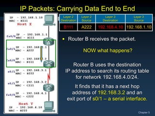
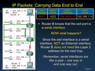
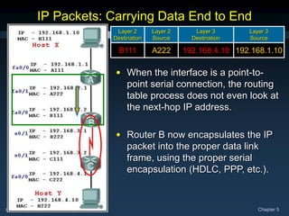
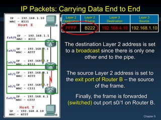
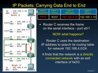
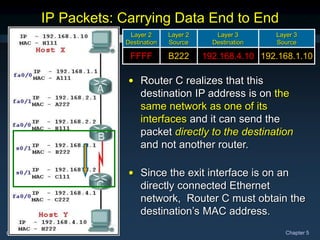
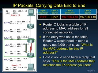
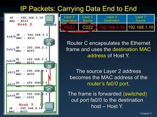
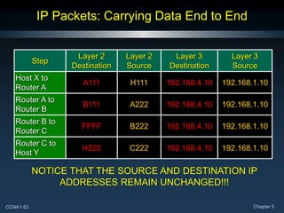
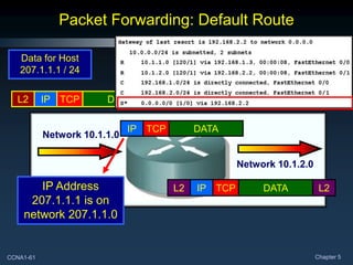
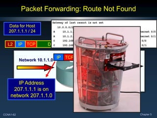
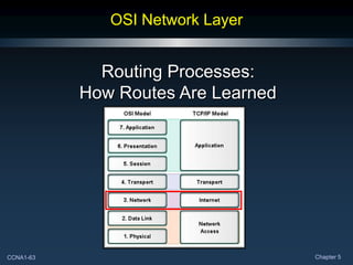
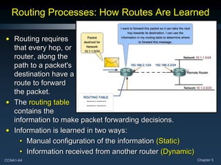
CCNA1-1 Chapter 5
Chapter 5
OSI Network Layer
CCNA1-2 Chapter 5
Note for Instructors
• These presentations are the result of a collaboration among
the instructors at St. Clair College in Windsor, Ontario.
• Thanks must go out to Rick Graziani of Cabrillo College. His
material and additional information was used as a reference
in their creation.
• If anyone finds any errors or omissions, please let me know
at:
• tdame@stclaircollege.ca.
CCNA1-3 Chapter 5
OSI Network Layer
Internet Protocol Version 4 (IPV4)
CCNA1-4 Chapter 5
Communication from Host to Host
As we communicate…
Devices use the Transport Layer
to connect sessions…
The network layer enables
devices to reach each other…
Routers find the
best path…
CCNA1-5 Chapter 5
Communication from Host to Host
• Addresses packets with an IP Address.
• Encapsulates the packet.
• Routes the packet to the destination.
• Decapsulates the packet.
Network
Layer
CCNA1-6 Chapter 5
Network Layer Protocols
• We will be focusing on IPV4.
CCNA1-7 Chapter 5
IPV4: Example Network Layer Protocol
• Internet Protocol Version 4 (IPV4) is the most widely used
version of IP.
• Only Layer 3 protocol used on the Internet.
• Focus of this course.
CCNA1-8 Chapter 5
IPV4: Example Network Layer Protocol
• Internet Protocol Version 6 (IPV6) is developed and slowly
being implemented. (More in CCNA-4)
• Will eventually replace IPV4.
• Different characteristics than IPV4.
CCNA1-9 Chapter 5
IPV4: Example Network Layer Protocol
• Characteristics:
• Connectionless
• “Best Effort” Delivery (Unreliable)
• Media Independent
CCNA1-10 Chapter 5
Connectionless
CCNA1-11 Chapter 5
“Best Effort” Delivery (Unreliable)
• Unreliable means simply that IP does not have the capability
to manage and recover from undelivered or corrupt packets.
• Since protocols at other layers can manage reliability, IP is
allowed to function very efficiently at the Network Layer.
CCNA1-12 Chapter 5
Media Independent
• Not concerned with the physical medium.
• Operates independent of the layers that handle the physical
medium that carries the packet.
CCNA1-13 Chapter 5
Media Independent
• Is concerned with
the size of the
packet or
Maximum
Transmission
Unit (MTU).
• The MTU is established as part of the communication
between the Data Link and Network Layers.
• Fragmentation:
• At times, an intermediary device (router) will need to split
up a packet when forwarding it from one media to a
media with a smaller MTU.
CCNA1-14 Chapter 5
Media Independent
• Copper Ethernet: MTU = 1,518 bytes.
• Copper Serial: Frame Relay MTU = 512 bytes.
• Optical Fiber: ATM MTU = 17,966 bytes.
• Wireless: 802.11 MTU = 2272 bytes.
CCNA1-15 Chapter 5
Packaging the Transport Layer PDU
In TCP/IP based networks, the Network Layer PDU is the
IP Packet.
CCNA1-16 Chapter 5
IPV4 Packet Header
32 Bit binary value.
Source of the packet
32 Bit binary value.
Destination of the packet
Maximum “hops”
before undeliverable.
8 1-bit fields -
Throughput Priority
Upper Layer Protocol
(TCP/UDP)
Used in reconstruction
of any fragments.
CCNA1-17 Chapter 5
OSI Network Layer
Networks: Dividing Hosts into Groups
CCNA1-18 Chapter 5
Dividing Hosts into Groups
As networks grow,
they become too
unwieldy to
manage as a
single entity.
Often, the solution is to divide the
large network into several more
manageable sub-networks.
The question is…..HOW?
CCNA1-19 Chapter 5
Dividing Hosts into Groups
Should it be
divided
geographically?
CCNA1-20 Chapter 5
Dividing Hosts into Groups
Should it be
divided based on
purpose?
CCNA1-21 Chapter 5
Dividing Hosts into Groups
Should it be
divided based on
ownership?
CCNA1-22 Chapter 5
Why Separate Hosts into Networks?
• Performance
• Security
• Address Management
CCNA1-23 Chapter 5
Performance
• Large numbers of
hosts on a single
network:
• Actual Data
• Overhead
• A big part of the
overhead is
broadcasts.
• In this context, each network is called a broadcast domain.
• Switches forward broadcasts to each device connected to a
switch port.
• If we can reduce broadcast overhead, it would improve
performance on the network.
A
CCNA1-24 Chapter 5
Performance
• Routers block
broadcasts unless
specifically
configured to
forward them.
• Replacing the
switch in the
diagram with a
router, creates two
separate IP sub-networks and two broadcast domains.
• Broadcasts are now contained within each network.
A B
X X
CCNA1-25 Chapter 5
Security
CCNA1-26 Chapter 5
Address Management
The role of the gateway….
CCNA1-27 Chapter 5
Hierarchical Addressing
1 2
3
4
IP Addresses are divided into a 2 level
hierarchy – Network and Host.
CCNA1-28 Chapter 5
Dividing Networks from Networks
• The IP Version 4 Address
contains elements that uniquely
identify both the network and
host.
• An IP Address is like a
telephone number:
• 519-972-2727
• 519 – Network Portion
• 972-2727 – Host Portion
• 519 – Windsor area
• 972-2727 - St. Clair College
CCNA1-29 Chapter 5
Dividing Networks from Networks
IP Version 4 addresses are 32 bits in length.
Divided into four separate groups of 8 bits each – 4 Octets.
Convert from binary to decimal – Dotted Decimal Notation.
CCNA1-30 Chapter 5
Dividing Networks from Networks
• An IP Version 4 address has two parts:
• Network number
• Host number
• The network portion of the address is the same for all
hosts on the network.
• Each device is identified by a unique host portion.
• This hierarchy means that routers only need to know the
network portion – not the address of each individual host.
CCNA1-31 Chapter 5
Dividing Networks from Networks
• There is a direct relationship, bit for bit, between the IP
Address and it's associated subnet mask.
• Any subnet mask bit that is a 1 means that the associated
address bit belongs to the network number.
• Any subnet mask bit that is a 0 means that the associated
address bit belongs to the host number.
IP Address 192. 168. 1. 2
Subnet Mask 255. 255. 255. 0
Binary IP Address 11000000 10101000 00000001 00000010
Binary Subnet Mask 11111111 11111111 11111111 00000000
CCNA1-32 Chapter 5
IP Addressing – The Subnet Mask
• There are two methods of expressing a subnet mask.
• The traditional method is to use the decimal value of the
1 bits that apply to the network.
• 192.168.1.2 255.255.255.0
• This method is used for Classful Routing .
• The new method is known as IP Prefix or CIDR.
• Simply follow the IP address with a slash (/) and the
number of bits that make up the network portion.
• The remainder of the 32 bits are for the host number.
• 192.168.1.2 / 24
• This method indicates Classless Routing or
Classless Interdomain Routing (CIDR).
CCNA1-33 Chapter 5
IP Addressing – The Subnet Mask
• The network portion of the IP address assigned to all hosts
on a network segment must be the same.
• All hosts on a segment have the same subnet mask.
CCNA1-34 Chapter 5
OSI Network Layer
Routing: How Data Packets Are Handled
CCNA1-35 Chapter 5
Address Types
• Two address types:
• MAC address:
• Physical address of
the host
• Burned in to the NIC
• Layer 2 address
• Network Address:
• Logical address of the
host
• Assigned by network
administrator
• Layer 3 address
CCNA1-36 Chapter 5
Each Host Has Two Addresses
• Physical (MAC):
• The physical address uniquely identifies the host from all
other hosts on all other networks at Layer 2.
• This is the address that is absolutely necessary to get the
information into the host. The IP address by itself won't
accomplish that.
CCNA1-37 Chapter 5
Each Host Has Two Addresses
• Logical (IP):
• The logical address uniquely identifies the host and the
network to which it belongs at Layer 3.
• Routers base their decisions on the NETWORK
PORTION of the IP address when determining the best
path for the packet.
CCNA1-38 Chapter 5
• Host X sends a packet to Host Y.
• A router generally relays a packet
from one data link to another, using
two basic functions:
• a path determination function –
Routing
• a switching function –
Packet Forwarding
• Let’s go through all of the stages
these routers use to route and
switch this packet.
IP Packets: Carrying Data End to End
Remember:
Two addresses are needed to
move a packet from the source to
the destination.
• MAC Address
• IP Address
CCNA1-39 Chapter 5
How does Host X know to forward
the packet to Router A and not
directly to Host Y?
IP Packets: Carrying Data End to End
Layer 2
Destination
Layer 2
Source
Layer 3
Destination
Layer 3
Source
A111 H111 192.168.4.10 192.168.1.10
• Host X begins by encapsulating a
packet with Host Y’s IP address and
Router A’s MAC address.
How does HOST X obtain
Router A’s Layer 2 address?
Host X determines that the
destination is NOT on the same
network. (More Later)
The packet is forwarded to the
default gateway.
Queries the router for the router’s
MAC address (more later).
CCNA1-40 Chapter 5
NOW what happens?
IP Packets: Carrying Data End to End
Layer 2
Destination
Layer 2
Source
Layer 3
Destination
Layer 3
Source
A111 H111 192.168.4.10 192.168.1.10
• Router A receives the packet on
port fa0/0.
Router A uses the destination
IP address to search its routing table
for network 192.168.4.0/24.
It finds that it has a next hop
address of 192.168.2.2 and an
exit port of fa0/1.
CCNA1-41 Chapter 5
NOW what happens?
IP Packets: Carrying Data End to End
Layer 2
Destination
Layer 2
Source
Layer 3
Destination
Layer 3
Source
A111 H111 192.168.4.10 192.168.1.10
• Router A knows that the exit port is
an Ethernet interface.
Router A looks in a table of IP
address to MAC address for all
connected networks. If the network
isn’t there, it queries Router B for it’s
MAC address.
CCNA1-42 Chapter 5
IP Packets: Carrying Data End to End
192.168.1.10
192.168.4.10
H111
A111
Layer 3
Source
Layer 3
Destination
Layer 2
Source
Layer 2
Destination
• Router A now has all of the
information it needs to forward the
packet. It knows that the
destination MAC address is B111
and that the exit port is fa0/0.
• Router A now re-encapsulates the
frame, changing the Layer 2
addresses and forwards (switches)
the frame out port fa0/1.
192.168.1.10
192.168.4.10
A222
B111
Layer 3
Source
Layer 3
Destination
Layer 2
Source
Layer 2
Destination
CCNA1-43 Chapter 5
192.168.1.10
192.168.4.10
A222
B111
Layer 3
Source
Layer 3
Destination
Layer 2
Source
Layer 2
Destination
IP Packets: Carrying Data End to End
• Notice that the Layer 3 addresses in
the packet DID NOT change!
• Also notice that the routing table
was used to find:
• The next hop Layer 3 address
• The next hop Layer 2 address
• The exit port to use to forward
the frame.
CCNA1-44 Chapter 5
192.168.1.10
192.168.4.10
A222
B111
Layer 3
Source
Layer 3
Destination
Layer 2
Source
Layer 2
Destination
IP Packets: Carrying Data End to End
• Router B receives the packet.
NOW what happens?
Router B uses the destination
IP address to search its routing table
for network 192.168.4.0/24.
It finds that it has a next hop
address of 192.168.3.2 and an
exit port of s0/1 – a serial interface.
CCNA1-45 Chapter 5
192.168.1.10
192.168.4.10
A222
B111
Layer 3
Source
Layer 3
Destination
Layer 2
Source
Layer 2
Destination
IP Packets: Carrying Data End to End
• Router B knows that the exit port is
a serial interface.
NOW what happens?
Since the exit interface is a serial
interface, NOT an Ethernet interface,
Router B does not need the Layer 2
address for the next hop.
Remember, serial interfaces are
like a pipe – one way in
and one way out.
CCNA1-46 Chapter 5
192.168.1.10
192.168.4.10
A222
B111
Layer 3
Source
Layer 3
Destination
Layer 2
Source
Layer 2
Destination
IP Packets: Carrying Data End to End
• When the interface is a point-to-
point serial connection, the routing
table process does not even look at
the next-hop IP address.
• Router B now encapsulates the IP
packet into the proper data link
frame, using the proper serial
encapsulation (HDLC, PPP, etc.).
CCNA1-47 Chapter 5
192.168.1.10
192.168.4.10
A222
B111
Layer 3
Source
Layer 3
Destination
Layer 2
Source
Layer 2
Destination
192.168.1.10
192.168.4.10
B222
FFFF
Layer 3
Source
Layer 3
Destination
Layer 2
Source
Layer 2
Destination
IP Packets: Carrying Data End to End
The destination Layer 2 address is set
to a broadcast since there is only one
other end to the pipe.
The source Layer 2 address is set to
the exit port of Router B – the source
of the frame.
Finally, the frame is forwarded
(switched) out port s0/1 on Router B.
CCNA1-48 Chapter 5
192.168.1.10
192.168.4.10
B222
FFFF
Layer 3
Source
Layer 3
Destination
Layer 2
Source
Layer 2
Destination
IP Packets: Carrying Data End to End
• Router C receives the frame
on the serial interface - port s0/1
NOW what happens?
Router C uses the destination
IP address to search its routing table
for network 192.168.4.0/24.
It finds that the network is a directly
connected network with an exit
interface of fa0/0.
CCNA1-49 Chapter 5
192.168.1.10
192.168.4.10
B222
FFFF
Layer 3
Source
Layer 3
Destination
Layer 2
Source
Layer 2
Destination
IP Packets: Carrying Data End to End
• Router C realizes that this
destination IP address is on the
same network as one of its
interfaces and it can send the
packet directly to the destination
and not another router.
• Since the exit interface is on an
directly connected Ethernet
network, Router C must obtain the
destination’s MAC address.
CCNA1-50 Chapter 5
192.168.1.10
192.168.4.10
B222
FFFF
Layer 3
Source
Layer 3
Destination
Layer 2
Source
Layer 2
Destination
IP Packets: Carrying Data End to End
• Router C looks in a table of IP
address to MAC address for all
connected networks.
• If the entry was not in the table,
Router C would need to send a
query out fa0/0 that says, “What is
the MAC address for this IP
address?”
• Host Y would send back a reply that
says, “This is the MAC address that
matches the IP Address you sent.”
CCNA1-51 Chapter 5
192.168.1.10
192.168.4.10
B222
FFFF
Layer 3
Source
Layer 3
Destination
Layer 2
Source
Layer 2
Destination
IP Packets: Carrying Data End to End
192.168.1.10
192.168.4.10
C222
H222
Layer 3
Source
Layer 3
Destination
Layer 2
Source
Layer 2
Destination
Router C encapsulates the Ethernet
frame and uses the destination MAC
address of Host Y.
The source Layer 2 address
becomes the MAC address of the
router’s fa0/0 port.
The frame is forwarded (switched)
out port fa0/0 to the destination
host – Host Y.
CCNA1-52 Chapter 5
IP Packets: Carrying Data End to End
Step
Layer 2
Destination
Layer 2
Source
Layer 3
Destination
Layer 3
Source
Host X to
Router A
A111 H111 192.168.4.10 192.168.1.10
Router A to
Router B
B111 A222 192.168.4.10 192.168.1.10
Router B to
Router C
FFFF B222 192.168.4.10 192.168.1.10
Router C to
Host Y
H222 C222 192.168.4.10 192.168.1.10
NOTICE THAT THE SOURCE AND DESTINATION IP
ADDRESSES REMAIN UNCHANGED!!!
CCNA1-53 Chapter 5
Gateway: The Way Out of the Network
• Default Gateway is defined to all hosts on the network.
• Gateway address is the address of the router interface.
• Network portion must be on the same network as all of
the hosts.
CCNA1-54 Chapter 5
Gateway: The Way Out of the Network
• Additionally, no packet can be forwarded without a route.
• A router makes a forwarding decision for each packet that
arrives at the gateway interface.
• The destination may be one or more hops away.
CCNA1-55 Chapter 5
Route: A Path to a Network
• The routing table stores information about directly connected
and remote networks.
• Remote networks are networks not directly connected to the
router (manual configuration or learned dynamically).
Destination
Network Next Hop
Metric
CCNA1-56 Chapter 5
Host Routing Table
• Hosts also require a local routing table so that Network layer
packets are directed to the correct destination network.
• Unlike a router, the host routing table usually contains only
the host’s address and the default gateway.
CCNA1-57 Chapter 5
Destination Network - Routing Table Entries
• The hierarchical nature of Layer 3 addressing means that…
• One route entry could refer to a large general network.
• Another entry could refer to a subnet of that same
network.
• When forwarding a packet, the router will select the most
specific route.
CCNA1-58 Chapter 5
Destination Network - Routing Table Entries
• The default route in a routing table performs much the same
function as a default gateway in a PC.
• If a route for a packet cannot be found in the routing
table, and a default route is present, that route will be
used to forward the packet.
CCNA1-59 Chapter 5
Destination Network - Routing Table Entries
• If a packet arrives destined for 207.23.124.56, the router
would check the table in the following order:
• 10.1.1.0
• 10.1.0.0
• 10.0.0.0
• 0.0.0.0
Since the route doesn’t exist
and a default route is
configured, the packet would be
forwarded to the next hop.
Destination
Network
Next Hop
Metric
CCNA1-60 Chapter 5
Packet Forwarding: Route Found
L2 IP TCP DATA L2
IP TCP DATA
Data for Host
10.1.2.2 / 24
Network 10.1.1.0
Network 10.1.2.0
L2 IP TCP DATA L2
IP Address
10.1.2.2 is on
network 10.1.2.0
CCNA1-61 Chapter 5
Packet Forwarding: Default Route
L2 IP TCP DATA L2
IP TCP DATA
Data for Host
207.1.1.1 / 24
Network 10.1.1.0
Network 10.1.2.0
L2 IP TCP DATA L2
IP Address
207.1.1.1 is on
network 207.1.1.0
CCNA1-62 Chapter 5
Packet Forwarding: Route Not Found
L2 IP TCP DATA L2
IP TCP DATA
Data for Host
207.1.1.1 / 24
Network 10.1.1.0
Network 10.1.2.0
IP Address
207.1.1.1 is on
network 207.1.1.0
?
CCNA1-63 Chapter 5
OSI Network Layer
Routing Processes:
How Routes Are Learned
CCNA1-64 Chapter 5
Routing Processes: How Routes Are Learned
• Routing requires
that every hop, or
router, along the
path to a packet's
destination have a
route to forward
the packet.
• The routing table
contains the
information to make packet forwarding decisions.
• Information is learned in two ways:
• Manual configuration of the information (Static)
• Information received from another router (Dynamic)
CCNA1-65 Chapter 5
Static Routing
• Manually configured.
• Must know network structure.
• Every router between each source and destination must have
routes.
• Changes to the topology require static route changes.
CCNA1-66 Chapter 5
Dynamic Routing
• Routing information is exchanged among the routers using a
routing protocol.
• Route always up to date with little administration but creates
overhead.
CCNA1-67 Chapter 5
Routing Protocols
• Routing Information Protocol (RIP)
• Enhanced Interior Gateway Protocol (EIGRP)
• Open Shortest Path First (OSPF)
CCNA1-68 Chapter 5

The network layer of the OSI model. Its functionality and protocols

  • 1.
    CCNA1-1 Chapter 5 Chapter5 OSI Network Layer
  • 2.
    CCNA1-2 Chapter 5 Notefor Instructors • These presentations are the result of a collaboration among the instructors at St. Clair College in Windsor, Ontario. • Thanks must go out to Rick Graziani of Cabrillo College. His material and additional information was used as a reference in their creation. • If anyone finds any errors or omissions, please let me know at: • tdame@stclaircollege.ca.
  • 3.
    CCNA1-3 Chapter 5 OSINetwork Layer Internet Protocol Version 4 (IPV4)
  • 4.
    CCNA1-4 Chapter 5 Communicationfrom Host to Host As we communicate… Devices use the Transport Layer to connect sessions… The network layer enables devices to reach each other… Routers find the best path…
  • 5.
    CCNA1-5 Chapter 5 Communicationfrom Host to Host • Addresses packets with an IP Address. • Encapsulates the packet. • Routes the packet to the destination. • Decapsulates the packet. Network Layer
  • 6.
    CCNA1-6 Chapter 5 NetworkLayer Protocols • We will be focusing on IPV4.
  • 7.
    CCNA1-7 Chapter 5 IPV4:Example Network Layer Protocol • Internet Protocol Version 4 (IPV4) is the most widely used version of IP. • Only Layer 3 protocol used on the Internet. • Focus of this course.
  • 8.
    CCNA1-8 Chapter 5 IPV4:Example Network Layer Protocol • Internet Protocol Version 6 (IPV6) is developed and slowly being implemented. (More in CCNA-4) • Will eventually replace IPV4. • Different characteristics than IPV4.
  • 9.
    CCNA1-9 Chapter 5 IPV4:Example Network Layer Protocol • Characteristics: • Connectionless • “Best Effort” Delivery (Unreliable) • Media Independent
  • 10.
  • 11.
    CCNA1-11 Chapter 5 “BestEffort” Delivery (Unreliable) • Unreliable means simply that IP does not have the capability to manage and recover from undelivered or corrupt packets. • Since protocols at other layers can manage reliability, IP is allowed to function very efficiently at the Network Layer.
  • 12.
    CCNA1-12 Chapter 5 MediaIndependent • Not concerned with the physical medium. • Operates independent of the layers that handle the physical medium that carries the packet.
  • 13.
    CCNA1-13 Chapter 5 MediaIndependent • Is concerned with the size of the packet or Maximum Transmission Unit (MTU). • The MTU is established as part of the communication between the Data Link and Network Layers. • Fragmentation: • At times, an intermediary device (router) will need to split up a packet when forwarding it from one media to a media with a smaller MTU.
  • 14.
    CCNA1-14 Chapter 5 MediaIndependent • Copper Ethernet: MTU = 1,518 bytes. • Copper Serial: Frame Relay MTU = 512 bytes. • Optical Fiber: ATM MTU = 17,966 bytes. • Wireless: 802.11 MTU = 2272 bytes.
  • 15.
    CCNA1-15 Chapter 5 Packagingthe Transport Layer PDU In TCP/IP based networks, the Network Layer PDU is the IP Packet.
  • 16.
    CCNA1-16 Chapter 5 IPV4Packet Header 32 Bit binary value. Source of the packet 32 Bit binary value. Destination of the packet Maximum “hops” before undeliverable. 8 1-bit fields - Throughput Priority Upper Layer Protocol (TCP/UDP) Used in reconstruction of any fragments.
  • 17.
    CCNA1-17 Chapter 5 OSINetwork Layer Networks: Dividing Hosts into Groups
  • 18.
    CCNA1-18 Chapter 5 DividingHosts into Groups As networks grow, they become too unwieldy to manage as a single entity. Often, the solution is to divide the large network into several more manageable sub-networks. The question is…..HOW?
  • 19.
    CCNA1-19 Chapter 5 DividingHosts into Groups Should it be divided geographically?
  • 20.
    CCNA1-20 Chapter 5 DividingHosts into Groups Should it be divided based on purpose?
  • 21.
    CCNA1-21 Chapter 5 DividingHosts into Groups Should it be divided based on ownership?
  • 22.
    CCNA1-22 Chapter 5 WhySeparate Hosts into Networks? • Performance • Security • Address Management
  • 23.
    CCNA1-23 Chapter 5 Performance •Large numbers of hosts on a single network: • Actual Data • Overhead • A big part of the overhead is broadcasts. • In this context, each network is called a broadcast domain. • Switches forward broadcasts to each device connected to a switch port. • If we can reduce broadcast overhead, it would improve performance on the network. A
  • 24.
    CCNA1-24 Chapter 5 Performance •Routers block broadcasts unless specifically configured to forward them. • Replacing the switch in the diagram with a router, creates two separate IP sub-networks and two broadcast domains. • Broadcasts are now contained within each network. A B X X
  • 25.
  • 26.
    CCNA1-26 Chapter 5 AddressManagement The role of the gateway….
  • 27.
    CCNA1-27 Chapter 5 HierarchicalAddressing 1 2 3 4 IP Addresses are divided into a 2 level hierarchy – Network and Host.
  • 28.
    CCNA1-28 Chapter 5 DividingNetworks from Networks • The IP Version 4 Address contains elements that uniquely identify both the network and host. • An IP Address is like a telephone number: • 519-972-2727 • 519 – Network Portion • 972-2727 – Host Portion • 519 – Windsor area • 972-2727 - St. Clair College
  • 29.
    CCNA1-29 Chapter 5 DividingNetworks from Networks IP Version 4 addresses are 32 bits in length. Divided into four separate groups of 8 bits each – 4 Octets. Convert from binary to decimal – Dotted Decimal Notation.
  • 30.
    CCNA1-30 Chapter 5 DividingNetworks from Networks • An IP Version 4 address has two parts: • Network number • Host number • The network portion of the address is the same for all hosts on the network. • Each device is identified by a unique host portion. • This hierarchy means that routers only need to know the network portion – not the address of each individual host.
  • 31.
    CCNA1-31 Chapter 5 DividingNetworks from Networks • There is a direct relationship, bit for bit, between the IP Address and it's associated subnet mask. • Any subnet mask bit that is a 1 means that the associated address bit belongs to the network number. • Any subnet mask bit that is a 0 means that the associated address bit belongs to the host number. IP Address 192. 168. 1. 2 Subnet Mask 255. 255. 255. 0 Binary IP Address 11000000 10101000 00000001 00000010 Binary Subnet Mask 11111111 11111111 11111111 00000000
  • 32.
    CCNA1-32 Chapter 5 IPAddressing – The Subnet Mask • There are two methods of expressing a subnet mask. • The traditional method is to use the decimal value of the 1 bits that apply to the network. • 192.168.1.2 255.255.255.0 • This method is used for Classful Routing . • The new method is known as IP Prefix or CIDR. • Simply follow the IP address with a slash (/) and the number of bits that make up the network portion. • The remainder of the 32 bits are for the host number. • 192.168.1.2 / 24 • This method indicates Classless Routing or Classless Interdomain Routing (CIDR).
  • 33.
    CCNA1-33 Chapter 5 IPAddressing – The Subnet Mask • The network portion of the IP address assigned to all hosts on a network segment must be the same. • All hosts on a segment have the same subnet mask.
  • 34.
    CCNA1-34 Chapter 5 OSINetwork Layer Routing: How Data Packets Are Handled
  • 35.
    CCNA1-35 Chapter 5 AddressTypes • Two address types: • MAC address: • Physical address of the host • Burned in to the NIC • Layer 2 address • Network Address: • Logical address of the host • Assigned by network administrator • Layer 3 address
  • 36.
    CCNA1-36 Chapter 5 EachHost Has Two Addresses • Physical (MAC): • The physical address uniquely identifies the host from all other hosts on all other networks at Layer 2. • This is the address that is absolutely necessary to get the information into the host. The IP address by itself won't accomplish that.
  • 37.
    CCNA1-37 Chapter 5 EachHost Has Two Addresses • Logical (IP): • The logical address uniquely identifies the host and the network to which it belongs at Layer 3. • Routers base their decisions on the NETWORK PORTION of the IP address when determining the best path for the packet.
  • 38.
    CCNA1-38 Chapter 5 •Host X sends a packet to Host Y. • A router generally relays a packet from one data link to another, using two basic functions: • a path determination function – Routing • a switching function – Packet Forwarding • Let’s go through all of the stages these routers use to route and switch this packet. IP Packets: Carrying Data End to End Remember: Two addresses are needed to move a packet from the source to the destination. • MAC Address • IP Address
  • 39.
    CCNA1-39 Chapter 5 Howdoes Host X know to forward the packet to Router A and not directly to Host Y? IP Packets: Carrying Data End to End Layer 2 Destination Layer 2 Source Layer 3 Destination Layer 3 Source A111 H111 192.168.4.10 192.168.1.10 • Host X begins by encapsulating a packet with Host Y’s IP address and Router A’s MAC address. How does HOST X obtain Router A’s Layer 2 address? Host X determines that the destination is NOT on the same network. (More Later) The packet is forwarded to the default gateway. Queries the router for the router’s MAC address (more later).
  • 40.
    CCNA1-40 Chapter 5 NOWwhat happens? IP Packets: Carrying Data End to End Layer 2 Destination Layer 2 Source Layer 3 Destination Layer 3 Source A111 H111 192.168.4.10 192.168.1.10 • Router A receives the packet on port fa0/0. Router A uses the destination IP address to search its routing table for network 192.168.4.0/24. It finds that it has a next hop address of 192.168.2.2 and an exit port of fa0/1.
  • 41.
    CCNA1-41 Chapter 5 NOWwhat happens? IP Packets: Carrying Data End to End Layer 2 Destination Layer 2 Source Layer 3 Destination Layer 3 Source A111 H111 192.168.4.10 192.168.1.10 • Router A knows that the exit port is an Ethernet interface. Router A looks in a table of IP address to MAC address for all connected networks. If the network isn’t there, it queries Router B for it’s MAC address.
  • 42.
    CCNA1-42 Chapter 5 IPPackets: Carrying Data End to End 192.168.1.10 192.168.4.10 H111 A111 Layer 3 Source Layer 3 Destination Layer 2 Source Layer 2 Destination • Router A now has all of the information it needs to forward the packet. It knows that the destination MAC address is B111 and that the exit port is fa0/0. • Router A now re-encapsulates the frame, changing the Layer 2 addresses and forwards (switches) the frame out port fa0/1. 192.168.1.10 192.168.4.10 A222 B111 Layer 3 Source Layer 3 Destination Layer 2 Source Layer 2 Destination
  • 43.
    CCNA1-43 Chapter 5 192.168.1.10 192.168.4.10 A222 B111 Layer3 Source Layer 3 Destination Layer 2 Source Layer 2 Destination IP Packets: Carrying Data End to End • Notice that the Layer 3 addresses in the packet DID NOT change! • Also notice that the routing table was used to find: • The next hop Layer 3 address • The next hop Layer 2 address • The exit port to use to forward the frame.
  • 44.
    CCNA1-44 Chapter 5 192.168.1.10 192.168.4.10 A222 B111 Layer3 Source Layer 3 Destination Layer 2 Source Layer 2 Destination IP Packets: Carrying Data End to End • Router B receives the packet. NOW what happens? Router B uses the destination IP address to search its routing table for network 192.168.4.0/24. It finds that it has a next hop address of 192.168.3.2 and an exit port of s0/1 – a serial interface.
  • 45.
    CCNA1-45 Chapter 5 192.168.1.10 192.168.4.10 A222 B111 Layer3 Source Layer 3 Destination Layer 2 Source Layer 2 Destination IP Packets: Carrying Data End to End • Router B knows that the exit port is a serial interface. NOW what happens? Since the exit interface is a serial interface, NOT an Ethernet interface, Router B does not need the Layer 2 address for the next hop. Remember, serial interfaces are like a pipe – one way in and one way out.
  • 46.
    CCNA1-46 Chapter 5 192.168.1.10 192.168.4.10 A222 B111 Layer3 Source Layer 3 Destination Layer 2 Source Layer 2 Destination IP Packets: Carrying Data End to End • When the interface is a point-to- point serial connection, the routing table process does not even look at the next-hop IP address. • Router B now encapsulates the IP packet into the proper data link frame, using the proper serial encapsulation (HDLC, PPP, etc.).
  • 47.
    CCNA1-47 Chapter 5 192.168.1.10 192.168.4.10 A222 B111 Layer3 Source Layer 3 Destination Layer 2 Source Layer 2 Destination 192.168.1.10 192.168.4.10 B222 FFFF Layer 3 Source Layer 3 Destination Layer 2 Source Layer 2 Destination IP Packets: Carrying Data End to End The destination Layer 2 address is set to a broadcast since there is only one other end to the pipe. The source Layer 2 address is set to the exit port of Router B – the source of the frame. Finally, the frame is forwarded (switched) out port s0/1 on Router B.
  • 48.
    CCNA1-48 Chapter 5 192.168.1.10 192.168.4.10 B222 FFFF Layer3 Source Layer 3 Destination Layer 2 Source Layer 2 Destination IP Packets: Carrying Data End to End • Router C receives the frame on the serial interface - port s0/1 NOW what happens? Router C uses the destination IP address to search its routing table for network 192.168.4.0/24. It finds that the network is a directly connected network with an exit interface of fa0/0.
  • 49.
    CCNA1-49 Chapter 5 192.168.1.10 192.168.4.10 B222 FFFF Layer3 Source Layer 3 Destination Layer 2 Source Layer 2 Destination IP Packets: Carrying Data End to End • Router C realizes that this destination IP address is on the same network as one of its interfaces and it can send the packet directly to the destination and not another router. • Since the exit interface is on an directly connected Ethernet network, Router C must obtain the destination’s MAC address.
  • 50.
    CCNA1-50 Chapter 5 192.168.1.10 192.168.4.10 B222 FFFF Layer3 Source Layer 3 Destination Layer 2 Source Layer 2 Destination IP Packets: Carrying Data End to End • Router C looks in a table of IP address to MAC address for all connected networks. • If the entry was not in the table, Router C would need to send a query out fa0/0 that says, “What is the MAC address for this IP address?” • Host Y would send back a reply that says, “This is the MAC address that matches the IP Address you sent.”
  • 51.
    CCNA1-51 Chapter 5 192.168.1.10 192.168.4.10 B222 FFFF Layer3 Source Layer 3 Destination Layer 2 Source Layer 2 Destination IP Packets: Carrying Data End to End 192.168.1.10 192.168.4.10 C222 H222 Layer 3 Source Layer 3 Destination Layer 2 Source Layer 2 Destination Router C encapsulates the Ethernet frame and uses the destination MAC address of Host Y. The source Layer 2 address becomes the MAC address of the router’s fa0/0 port. The frame is forwarded (switched) out port fa0/0 to the destination host – Host Y.
  • 52.
    CCNA1-52 Chapter 5 IPPackets: Carrying Data End to End Step Layer 2 Destination Layer 2 Source Layer 3 Destination Layer 3 Source Host X to Router A A111 H111 192.168.4.10 192.168.1.10 Router A to Router B B111 A222 192.168.4.10 192.168.1.10 Router B to Router C FFFF B222 192.168.4.10 192.168.1.10 Router C to Host Y H222 C222 192.168.4.10 192.168.1.10 NOTICE THAT THE SOURCE AND DESTINATION IP ADDRESSES REMAIN UNCHANGED!!!
  • 53.
    CCNA1-53 Chapter 5 Gateway:The Way Out of the Network • Default Gateway is defined to all hosts on the network. • Gateway address is the address of the router interface. • Network portion must be on the same network as all of the hosts.
  • 54.
    CCNA1-54 Chapter 5 Gateway:The Way Out of the Network • Additionally, no packet can be forwarded without a route. • A router makes a forwarding decision for each packet that arrives at the gateway interface. • The destination may be one or more hops away.
  • 55.
    CCNA1-55 Chapter 5 Route:A Path to a Network • The routing table stores information about directly connected and remote networks. • Remote networks are networks not directly connected to the router (manual configuration or learned dynamically). Destination Network Next Hop Metric
  • 56.
    CCNA1-56 Chapter 5 HostRouting Table • Hosts also require a local routing table so that Network layer packets are directed to the correct destination network. • Unlike a router, the host routing table usually contains only the host’s address and the default gateway.
  • 57.
    CCNA1-57 Chapter 5 DestinationNetwork - Routing Table Entries • The hierarchical nature of Layer 3 addressing means that… • One route entry could refer to a large general network. • Another entry could refer to a subnet of that same network. • When forwarding a packet, the router will select the most specific route.
  • 58.
    CCNA1-58 Chapter 5 DestinationNetwork - Routing Table Entries • The default route in a routing table performs much the same function as a default gateway in a PC. • If a route for a packet cannot be found in the routing table, and a default route is present, that route will be used to forward the packet.
  • 59.
    CCNA1-59 Chapter 5 DestinationNetwork - Routing Table Entries • If a packet arrives destined for 207.23.124.56, the router would check the table in the following order: • 10.1.1.0 • 10.1.0.0 • 10.0.0.0 • 0.0.0.0 Since the route doesn’t exist and a default route is configured, the packet would be forwarded to the next hop. Destination Network Next Hop Metric
  • 60.
    CCNA1-60 Chapter 5 PacketForwarding: Route Found L2 IP TCP DATA L2 IP TCP DATA Data for Host 10.1.2.2 / 24 Network 10.1.1.0 Network 10.1.2.0 L2 IP TCP DATA L2 IP Address 10.1.2.2 is on network 10.1.2.0
  • 61.
    CCNA1-61 Chapter 5 PacketForwarding: Default Route L2 IP TCP DATA L2 IP TCP DATA Data for Host 207.1.1.1 / 24 Network 10.1.1.0 Network 10.1.2.0 L2 IP TCP DATA L2 IP Address 207.1.1.1 is on network 207.1.1.0
  • 62.
    CCNA1-62 Chapter 5 PacketForwarding: Route Not Found L2 IP TCP DATA L2 IP TCP DATA Data for Host 207.1.1.1 / 24 Network 10.1.1.0 Network 10.1.2.0 IP Address 207.1.1.1 is on network 207.1.1.0 ?
  • 63.
    CCNA1-63 Chapter 5 OSINetwork Layer Routing Processes: How Routes Are Learned
  • 64.
    CCNA1-64 Chapter 5 RoutingProcesses: How Routes Are Learned • Routing requires that every hop, or router, along the path to a packet's destination have a route to forward the packet. • The routing table contains the information to make packet forwarding decisions. • Information is learned in two ways: • Manual configuration of the information (Static) • Information received from another router (Dynamic)
  • 65.
    CCNA1-65 Chapter 5 StaticRouting • Manually configured. • Must know network structure. • Every router between each source and destination must have routes. • Changes to the topology require static route changes.
  • 66.
    CCNA1-66 Chapter 5 DynamicRouting • Routing information is exchanged among the routers using a routing protocol. • Route always up to date with little administration but creates overhead.
  • 67.
    CCNA1-67 Chapter 5 RoutingProtocols • Routing Information Protocol (RIP) • Enhanced Interior Gateway Protocol (EIGRP) • Open Shortest Path First (OSPF)
  • 68.