Television Technology Demystified 1st Edition Aleksandar Louis Todorovic
Television Technology Demystified 1st Edition Aleksandar Louis Todorovic
Television Technology Demystified 1st Edition Aleksandar Louis Todorovic
Television Technology Demystified 1st Edition Aleksandar Louis Todorovic
Television Technology Demystified 1st Edition Aleksandar Louis Todorovic
1.
Television Technology Demystified1st Edition
Aleksandar Louis Todorovic download
https://ebookbell.com/product/television-technology-
demystified-1st-edition-aleksandar-louis-todorovic-1022188
Explore and download more ebooks at ebookbell.com
2.
Here are somerecommended products that we believe you will be
interested in. You can click the link to download.
Television Technology And Cultural Form 3rd Raymond Williams
https://ebookbell.com/product/television-technology-and-cultural-
form-3rd-raymond-williams-1273200
Digital Television Technology And Standards John F Arnold Michael R
Frater
https://ebookbell.com/product/digital-television-technology-and-
standards-john-f-arnold-michael-r-frater-1076166
Modern Cable Television Technology Video Voice And Data Communications
2nd Ed Walter Ciciora
https://ebookbell.com/product/modern-cable-television-technology-
video-voice-and-data-communications-2nd-ed-walter-ciciora-4342038
Dictionary Of Video Television Technology Book Cd Rom Keith Jack
https://ebookbell.com/product/dictionary-of-video-television-
technology-book-cd-rom-keith-jack-931822
3.
3d Television 3dtvTechnology Systems And Deployment Rolling Out The
Infrastructure For Nextgeneration Entertainment 1st Edition Daniel
Minoli
https://ebookbell.com/product/3d-television-3dtv-technology-systems-
and-deployment-rolling-out-the-infrastructure-for-nextgeneration-
entertainment-1st-edition-daniel-minoli-2153042
Digital Terrestrial Television Broadcasting Technology And System 1st
Edition Jian Song
https://ebookbell.com/product/digital-terrestrial-television-
broadcasting-technology-and-system-1st-edition-jian-song-5223966
Frames Of Mind A Postjungian Look At Cinema Television And Technology
Luke Hockley
https://ebookbell.com/product/frames-of-mind-a-postjungian-look-at-
cinema-television-and-technology-luke-hockley-2369864
Newnes Guide To Television And Video Technology Third Edition 3rd
Edition Eugene Trundle
https://ebookbell.com/product/newnes-guide-to-television-and-video-
technology-third-edition-3rd-edition-eugene-trundle-4150002
Newnes Guide To Television And Video Technology 4th Edition K F
Ibrahim
https://ebookbell.com/product/newnes-guide-to-television-and-video-
technology-4th-edition-k-f-ibrahim-977644
Television Technology
Demystified
A Non-technicalGuide
Aleksandar Louis Todorović
AMSTERDAM • BOSTON • HEIDELBERG • LONDON
NEW YORK • OXFORD • PARIS • SAN DIEGO
SAN FRANCISCO • SINGAPORE • SYDNEY • TOKYO
Focal Press is an imprint of Elsevier
Contents
Introduction ix
1
Development ofTelevision Technology—A Sweep through History 1
1.1. Optoelectric Transformation 1
1.2. The Nipkow Disk 3
1.3. The Cathode-Ray Tube 5
1.4. The Birth of Television 6
2
Light and the Human Eye 11
2.1. Light in Television Production 11
2.2. The Nature of Light and Human Vision 12
2.3. White Light and Color Temperature 14
2.4. Monochromatic Light 16
2.5. Color Matching 17
2.6. Measurement of Light 20
3
Generating a Television Picture 23
3.1. Picture Scanning 23
3.2. Progressive and Interlaced Scanning 26
3.3. The Basic Video Signal 29
v
11.
vi Contents
4
Color Television33
4.1. Splitting the White Light and the Selection of Primaries 34
4.2. Picture Generation or Optoelectric Conversion 37
4.3. Picture Display 38
4.4. Transmission Path 41
4.5. The Principle of Modulation 43
4.6. The NTSC System 46
4.7. The PAL System 48
4.8. The SECAM System 49
4.9. Transcoding and Standards Conversion 52
5
Digital Television 55
5.1. What Is a Digital Signal? 55
5.2. Analog-to-Digital Conversion 57
5.3. Why a Digital Signal? 61
5.4. Digital Standards Conversion 63
5.5. The International Digitization Standard 65
5.6. Convergence 70
6
Digital Compression as the
Key to Success 73
6.1. Why Compression? 73
6.2. Compression Methods and Tools 75
6.3. The MPEG-2 Bit-Rate Reduction Method 80
6.4. Exploiting the Spatial Redundancy 82
6.5. Exploiting the Statistical Redundancy—Entropy Coding 82
6.6. Exploiting the Temporal Redundancy 83
6.7. Compression Levels and Applications 87
6.8. DV Compression 88
6.9. The MPEG-4 Compression System 90
6.10. Compression and Picture Quality 94
6.11. Concatenation Loss 95
12.
Contents vii
7
Digital AudioCompression Methods 97
7.1. Human Auditory System 97
7.2. Analog-to-Digital Conversion of Audio Signals 100
7.3. Digital Audio Compression 102
7.4. Audio Compression Methods and Standards 103
8
Exchanging Program Material as Bitstreams 111
8.1. File Transfer 112
8.2. Metadata 116
8.3. Material Exchange Format—MXF 122
8.4. AAF and Other File Formats 125
9
Television Cameras 131
9.1. The Optical System 132
9.2. Sensors 137
9.2.1. Pick-Up Tubes 138
9.2.2. Solid-State Sensors 140
9.2.3. Operating Principles of CCDs 142
9.3. Camera Processing Circuitry 148
9.4. Basic Quality Parameters 151
9.4.1. Noise level 151
9.4.2. Resolution 152
9.4.3. Spectral characteristic 153
9.4.4. Sensitivity 153
10
Video Recording 155
10.1. The Evolution of Videotape Recorders 155
10.2. Basic Principles of Magnetic Recording 158
10.3. Practical Recording Characteristics—Losses 163
10.4. Specific VTR Problems and Their Solutions 164
10.5. Videotape Recording Formats 168
10.6. Videotape Recording Methods 173
13.
viii Contents
10.7. AzimuthRecording 176
10.8. Digital Videotape Recording 179
10.9. Tapeless Recording 186
11
Video Editing 193
11.1. The Development of Video Editing 193
11.2. Linear Editing 197
11.3. Time Code 200
11.4. Nonlinear Editing (NLE) 202
12
The Networked Production 209
12.1. Basic Aspects of Networked Systems 211
12.2. Media Asset Management Systems 214
12.3. Integrated Digital Newsroom Operations 217
13
Television Graphics 225
13.1. Basic Technical Requirements 225
13.2. Computer Generated Imaging 228
13.3. Character Generators 229
13.4. Graphics Workstations 230
13.5. Virtual Sets 233
13.6. Selecting a Computer Graphics System 236
14
HDTV 239
14.1. Development of the HDTV Concept and Technology 239
14.2. HDTV Production Equipment 243
14.3. HDTV and D-Cinema 245
Acronyms and Selected Abbreviations 251
Index 261
14.
Introduction
We experience theworld around us by seizing its sights and sounds. Science has
proven that sight is possible because our eyes are able to capture and our brains to
decipher the electromagnetic radiation that is light, at certain frequencies. In the
same way, we hear sounds, which are the vibrations of air particles whose fre-
quencies are within the sensing abilities of our ear-brain combination. Since the
dawn of civilization, humanity has desired to fix, transport, and recreate these
sights and sounds. However, for millennia the only way to pass along this infor-
mation was to transform it into spoken or written words. These had the power to
ignite our imaginations but could not offer the benefit of direct experience that a
virtual replica of the sounds and sights witnessed by a narrator or author could
provide.
By the end of the nineteenth and the beginning of the twentieth century we
had discovered how to transmit sounds over long distances, then how to record
sound and then visual information, and eventually, with television, how to trans-
port sights and sounds instantly over great distances. A television system can be
simply described as a complex device that transforms light and sounds into elec-
trical signals, transports those signals over very long distances, and transforms
them back into light and sounds. Over the last 60 years, televised moving images
have grown into the most powerful system of transmission of ideas, concepts,
and thoughts, but also into the most powerful entertainment medium the world
has ever known. Just as the nineteenth could be defined as the century of steam
power, the omnipresence and influence of television makes it legitimate to define
the twentieth century as the century of television.
Digital technology facilitates the creation of new production tools that are
more reliable and simpler to operate than analog tools. Gone are the long and
tedious daily alignments of myriad parameters. Present-day equipment can be
safely used without the permanent presence and devoted care of skilled engineers.
At the same time, those digital and computer-based tools offer considerably more
creative possibilities than their analog predecessors. But all these capabilities can
ix
15.
x Introduction
only befully exploited if users know the basic operating principles of how the
equipment works, which should then help them understand its power as well as
its limitations.
The aim of this book is to help all current and future nontechnical members
of a production team become familiar with the technical fundamentals of analog
and digital television, the operation of essential elements of a television pro-
duction chain, and the possibilities and limitations of these production tools.
All descriptions and explanations in this book will be nonmathematical, and
essential concepts and parameters will be easy to understand without the need
to call upon previous scientific or engineering knowledge. The author hopes that
this book will prove to be particularly useful for all students in communications,
film, and television departments, for all those future program creators and media
professionals who should acquire during their education process a good insight
into the modus operandi of modern television production tools.
The reader will notice that this book covers mainly the video aspect of television
production. Such a focus was purposefully selected not only because covering all
aspects of audio production would require many additional chapters but also
because that subject is already very well described in a number of excellent and
easily understandable books. However, since compressed audio signals determine
a number of important aspects of digital recording, file-transfer mechanisms, and
media asset-management systems, it proved necessary to dedicate one chapter to
digital audio and digital audio compression.
The development of television production technology is moving at an increas-
ingly rapid pace. Not only new pieces of equipment but also new concepts and
technologies appear daily on the market. Therefore, the reader should note that
all references to “modern” or “current” solutions or systems correspond to the
state of the art in the year 2005.
16.
1
Development of Television
Technology—ASweep through
History
Today, in the first years of the twenty-first century, we take for granted a number
of technological marvels that are irreplaceable components of our everyday life.
Having lived in the century that witnessed the development of marvels such as
aviation, telecommunications, cars, and television, we tend to forget that almost
all the core discoveries and breakthroughs that were essential for the develop-
ment of these technologies were made during that fascinatingly entrepreneurial
nineteenth century. Television is undoubtedly one of these marvels.
The simplest definition of television is that it is the transmission of moving
images at a distance and that its workings can be compared to that of the human
visual system. The eye captures the light reflected from an object in the surround-
ing world and transforms that photo energy into neural impulses. These impulses
travel to the brain where they are deciphered and, through processes still only par-
tially understood, transformed into a mental reproduction of the original object. In
television, as in human vision, the first step in the process of achieving transmis-
sion is to transform the light reflected from the world around us into another form
of energy. In this case it is transformed into electric energy, which is then handled,
memorized, or transmitted by means of specific methods and techniques.
1.1 Optoelectric Transformation
The first of the series of nineteenth-century discoveries that would eventually
become the basis of television was the essential discovery of optoelectric conver-
sion. Interestingly, this important discovery was made by chance rather than as
a result of serious scientific research. In 1873 an Irish telegraph operator named
1
17.
2 Development ofTelevision Technology—A Sweep through History
Leonard May observed that his telegraph behaved differently depending on the
time of day. Upon further investigation he realized that a selenium bar, which
was part of the apparatus, changed its resistance in relation to the amount of
sunlight falling on it. In full sunlight there was less resistance, but resistance
increased as the sun moved toward the horizon. This photoelectric (or optoelec-
tric) phenomenon was not to be used in television technology for another 80 years
or so, but it should be recognized as one of the most important milestones—the
first registered transformation of the energy of light into electric energy. The phe-
nomenon discovered by May (who, incidentally, never profited from it) would
later be named photoconductivity.
Photoelectric phenomena, that is, changes in the behavior of electrons due to
variations in amount of light illuminating a given material, were at that time
being scrutinized by a number of scientists. In 1888 a German physicist, Wilhelm
Hallwachs, discovered another very important photoelectric phenomenon—
photoemission. Photoemission is the act of releasing free electrons in the surround-
ing space. Namely some materials have a greater or more modest capacity to
release, or as it is usually said, emit free electrons under the impact of light. The
number of emitted electrons is directly proportional to the intensity of the incom-
ing light. In other words, the brighter the light illuminating the piece of material,
the more free electrons will appear. This physical property would be used to
develop the first television experiments some 30 years later.
The first theoretical descriptions of a hypothetical television system, proposed
by George Carey in the United States as early as 1875, advocated the use of a
mosaic structure similar to the structure of the human eye. He proposed to assem-
ble two mosaics—one of photosensitive cells possessing the capacity to produce
at each point an electric charge proportional to the amount of light falling on that
particular element, and the other of cells that would display a reverse effect, that
is, would produce a certain quantity of light proportional to the received electric
impulse. According to Carey, if all cells belonging to these two panels were mutu-
ally connected with pairs of wires, one to one, it would be possible to transmit
an optical moving picture at a given distance.
Theoretically, such a parallel channel system could allow the transmission
of moving images but only theoretically as the obstacles to its realization were
numerous. First, in 1875 the necessary technology for its materialization was not
available. Second, and even more important, there were so many elements that
had to be connected at the same time; a simultaneous system of transmission was
and still is very cumbersome and very difficult to achieve in practice. Using a large
number of parallel channels for the transmission of one single piece of information
was not a viable solution, either economically or technically. One of the basic
economic principles in communications is to use always the minimum channel
capacity, i.e. the narrowest channel possible, or in some instances the minimum
18.
1.2 The NipkowDisk 3
number of channels for the transmission of maximum information. From the
technical point of view, it is always preferable to use one single channel instead
of a number of parallel ones since all parallel channels should behave identically
under all circumstances, and, practically speaking, that is almost impossible to
achieve.
The only viable alternative to a simultaneous capturing and transmission system
is to analyze, or scan, the picture to be transmitted by dissecting it into a series
of tightly spaced consecutive pieces of information and sending them through one
single channel. Since these discrete elements will be displayed at the receiving end
in very quick succession, the human visual system will not see them as a series
of separate pieces of information but will integrate them into a single picture.
Experiments have shown that the most appropriate method of scanning is linear
scanning, that is, the analysis of individual picture elements, one by one, disposed
on consecutive parallel horizontal lines. The number of picture elements analyzed
and the number of scanning lines used will determine the resolution of the system,
that is, its capacity to reproduce fine details.
1.2 The Nipkow Disk
The first scanning device was developed in 1884 by Paul Nipkow, a German
physicist of Polish origin. He made a special perforated disk designed for a
point-by-point analysis, that is, for scanning of optical pictures. This mechani-
cal scanning device disassembled simultaneous optical pictures into a number of
discrete partial elements. It consisted of a flat circular plate that rotated around
an axis located at its center. It was perforated with a number of holes following
a spiral path from the center to the outside of the disk (see Figure 1.1.).
If the light reflected from a picture to be transmitted is projected with an optical
lens to a certain area of the rotating disk, only discrete values of points of illu-
mination will pass through the perforations to the other side of the disk, there to
fall on a photosensitive element. That element will consequently generate a quick
succession of electric charges proportional to the quantity of light falling on it at
a given moment. The holes on the rotating disk will, in fact, scan the projected
optical picture line by line, and the photosensitive element will generate a contin-
uous electric stream of variable intensity. The net result of that operation is that
the simultaneous optical picture is transformed into a continuous stream of dis-
crete, sequentially transmitted information whose transmission requires just one
channel. One full rotation of the disk scans one full optical picture. The number of
holes in the disk will determine the number of lines used to scan or analyze one
picture and the number of sequentially analyzed pictures will therefore depend
on the rotational speed of the disk—a faster rotational speed will mean more
19.
4 Development ofTelevision Technology—A Sweep through History
Figure 1.1 Nipkow disk: The first television scanning device.
full rotations in a unit of time and consequently more scanned/analyzed pictures
during that same unit of time. At the same time it is well known that a quick suc-
cession of static pictures is integrated by the human visual system as a continuous
reproduction of movement.
The electric signal thus generated can be transmitted over a distance by any
standard wire or wireless transmission method. However, at the end of the chain it
has to be transformed again into a light picture so that the human eye can perceive
it. The first experimental television installations used two Nipkow disks—one to
scan the optical picture and the other to perform the role of a display device. The
latter rotated between the eyes of the viewer and the light source as it changed
its radiated light power in relation to the intensity of the incoming electric signal.
If both rotating disks were fully synchronous (meaning that they start and stop
rotating at the same time and that their rotational speeds are identical) and in
phase (meaning that the positions of the holes on both disks compared to the
scanned object are always identical, i.e. when the hole number one of the first
disk is at the upper left corner of the projected picture the hole number one of the
second disk should be at the corresponding position of the reproduced picture),
the holes of the display disk would reconstruct, line by line, the transmitted
picture. Such a system was acceptable for the early experiments in which the
20.
1.3 The Cathode-RayTube 5
picture was reduced to black shadows on a white background and the resolution
was limited to about 60 lines. But the systems based on a Nipkow disk were
hobbled by the limitations of the disks: they were crude mechanical devices,
burdened by inertia and synchronization problems as well as by the inability of
early artificial light sources to react adequately to the extremely fast changes of the
incoming signal. In order to reproduce all the tones from black to white passing
by different shades of gray (the gray scale), the light source would have to have
been capable of changing its intensity several hundred times in the course of one
television line, that is, during one 60th of the duration of one picture, which means
during one fraction of a second. However, there was practically no incandescent
light source capable of such performance.
1.3 The Cathode-Ray Tube
Further research in the development of television shows that even by the stan-
dards of the period, the Nipkow disk was not a viable solution for the display of
transmitted moving images. Fortunately, by the end of the nineteenth century
another German physicist, Ferdinand Braun, developed the cathode-ray tube
(CRT), the essential and basic television display device. This device, shown in
Figure 1.2, is equipped with two electrodes connected through an electric circuit.
The first of these electrodes is the cathode—an element capable of emitting free elec-
trons under the effect of thermal heating. The other electrode, called the anode, is
installed at the opposite side of the glass tube and is at a positive electric potential
and therefore attracts these negatively charged electrons. In the neck of the glass
tube, past the cathode, there are several plates connected to sources of electricity.
Glass tube
Cathode
Focusing
elements
Scanning coils
Electron beam
Phosphor
coating
Figure 1.2 Simplified representation of the cross section of a Braun CRT.
21.
6 Development ofTelevision Technology—A Sweep through History
Thanks to the electrical power supplied here, a field (called an electrostatic field)
is created between the plates and acts as a sort of electrical lens focusing the lib-
erated electrons into a concentrated beam flowing toward the anode that attracts
the electrons. Outside the tube, around its neck, two coils are mounted. These
coils are connected to another electric source. The current flowing through the
windings of the coils creates a magnetic field in the glass tube that has the ability
to move the electron beam. The magnetic fields created by these two coils are in
fact responsible for the scanning movement of the beam over the front surface of
the tube. The anode part of the tube is covered with a phosphor coating—a spe-
cial material that emits visible light at the point of impact of the electron beam.
The intensity of that light is directly proportional to the intensity of the beam at
the moment of impact. Adequately created electromagnetic fields can control the
movement of the electron beam, making it scan the front end of the tube at a
selected scanning speed.
By the beginning of the twentieth century, the three essential elements of a
television chain—the optoelectric conversion, the scanning of the optical picture,
and the electro-optic transformation—were in place. However, several elements
were still missing: a better understanding of the behavior and propagation of
electromagnetic waves; the mastering of the amplification of electrical signals;
and the expertise, discoveries, and developments that would be achieved by great
scientists like Marconi, Tesla, Lee de Forest, and Branly. Also missing at the time
was the person who would seize the moment when relevant discoveries reached
critical mass and who would have the courage and ability to envision bringing
together these discoveries in order to transform a science-fiction toy into a physical
reality. More than 20 years would elapse before the first crude moving images
would be transmitted between two adjacent rooms on Frith Street in London.
1.4 The Birth of Television
By the early 1920s two visionaries began almost simultaneously but indepen-
dently to develop a chain capable of transmitting moving images. In 1923 Charles
Francis Jenkins in the United States and John Logie Baird in United Kingdom (see
Figure 1.3) presented the results of their experiments. The images they showed
were just black shadows, cruder than children’s shadow puppets against a white
wall, and the distance of transmission was limited to several meters between the
transmitter and the receiver that were located in adjacent rooms, but it was the
first time that moving images were transmitted. Encouraged by these first results,
both men continued with their work and by 1925 were able to demonstrate pic-
tures with halftones, that is, pictures with different shades of gray corresponding
to different grades of illumination from the black level to the brightest white.
22.
1.4 The Birthof Television 7
Figure 1.3 John Logie Baird.
The resolution and the quality of the transmitted gray scale was certainly very
limited, but nevertheless these were “real” pictures, and, consequently, 1925 is
considered the year when television was born.
Even after that auspicious beginning, 10 additional years of research and devel-
opment elapsed before the first television service was introduced. The efforts
of pioneers like Baird and Jenkins were not enough. The creation of television
would demand the efforts of a number of other researchers and the endeavors of
powerful companies such as RCA, EMI, and Telefunken, along with a gradually
developing general awareness of the importance and the potential of that new
medium.
Both Jenkins and Baird based their television systems on mechanical scan-
ning of optical images with Nipkow disks. Presumably they were aware of the
limitations of mechanical systems and even knew the theoretical arguments of
Boris Rosing from Russia and Alan Archibald Campbell-Swinton from the United
Kingdom, published in 1911, that proved that television would be viable only if
23.
8 Development ofTelevision Technology—A Sweep through History
all elements of its chain were electric. But in the 1920s, the only available scanning
device was mechanical.
Baird’s activities—his public appearances, his public demonstrations of
improved pictures and devices, and his advocacy of the importance of television—
eventually changed public opinion, and in the early 1930s, British official
authorities began discussions on a possible introduction of a limited television
service. By that time Baird’s company was no longer the sole developer of tele-
vision. It had to face a formidable competitor—the EMI Company under the
dynamic leadership of Isaac Shoenberg.
When they started their research, scientists at the EMI labs had read about the
work of Philo Farnsworth and Vladimir Zworykine who worked on the develop-
ment of electronic scanning, or pick-up, devices and they took these achievements
as their starting point. Consequently, the concept of the EMI television system
was fully based on Campbell-Swinton and Rosing’s postulates—it was an all-
electric system, from the pick-up through transmission to the display, based on
an improved version of Braun’s CRT.
Faced with two contenders, the post office (which was at the state level in
charge of the whole field of telecommunications) and the BBC (who already
ran a nationwide radio service) decided to organize a parallel public testing of
both systems—the mechanical/electrical system proposed by Baird, operating at
240 lines, and the all-electric EMI system that offered (as it was advertised at that
time) “high definition” at 405 lines.
Two studios were set up in Alexandra Palace in London (see Figure 1.4), one
equipped by Baird and the other by EMI. On alternate days, programs were aired
Figure 1.4 Alexandra Palace today. (Courtesy J. Todorovic, Belgrade)
24.
1.4 The Birthof Television 9
from one or the other studio and received on several receivers scattered around
the city. At the end of the test period, the result was clear cut: the EMI system was
unequivocally superior and was therefore officially selected as a standard for the
planned television service. And so the beginning of the first public television
service in 1936 was, paradoxically, a victory for Baird, who had toiled for
15 years advocating the cause of television, but also a defeat of the system that
he had developed.
2
Light and theHuman Eye
It might perhaps be expected that this discussion should begin by saying what light really is; but this is not
possible, since light is more primitive that any of the terms that might be used in an effort to explain it. The
nature of light is describable only by enumerating its properties and founding them on the simplest possible
principles. As these principles transcend ordinary experience they must be cast in a purely logical (mathematical)
form … .
—Encyclopedia Britannica
Acknowledging the statement above, we can say that light is a physical
phenomenon that we perceive through our sense of sight. We see the world
around us thanks to the light reflected by the objects in it. Such a definition leads
us immediately to the next statement—any discussion related to light has to take
into account both its physical properties and the human psychological reaction to
those properties. We know that the most essential element in a television system
is the conversion of light to electricity (optoelectric conversion) at the beginning
of the chain and the conversion of electricity back into light (electro-optic con-
version) at its end. Consequently, light, its characteristics, and its usage are of a
paramount importance for the technology of television as everything starts and
ends with light.
2.1 Light in Television Production
In any visual production—film, television, or theater—light is one of the most
important creative tools. In film and television it is also the prerequisite for normal
camera operation because, after all, what we are looking at is merely a reflection of
light into the lens. It could be said that lighting in theater, film, and television is a
mixture of creativity and technology. Good lighting requires a lot of imagination
and creativity but also an excellent knowledge of the technology used as well
as precise planning and an understanding of the features and limitations of the
whole video chain.
11
27.
12 Light andthe Human Eye
Lighting in television has to fulfill a certain number of functions, which,
according to Alan Wurtzel (Wurtzel&Rosenbaum 1995), can be summarized in
the following way:
1. To satisfy the requirements of the technical system. In other words, there
must be a general light level that will ensure normal operation of television
cameras. The absolute level depends on the type of cameras used, but in
general terms, the light level should be such that it ensures an optimum
photographic quality of the output video signal when the iris aperture is set
at a middle value.
2. To create a three-dimensional (3D) effect. Television pictures are two-
dimensional (2D) and so are defined by their height and width. The third
dimension, the depth, is the result of the angle of shooting, set design,
and creative lighting. Good lighting will considerably enhance the desired
3D effect.
3. To give prominence to some parts of the picture. Light and shadow can
be very well used to attract the viewer’s attention to different areas of the
scene or of the shot.
4. To define the atmosphere. Light can be used to define the atmosphere of
the scene. Dark, shadowy shots will indicate tension, drama, or mystery
while brightly lit scenes will suggest happiness, joy, or cheerfulness.
5. To define the time of action. Light can be used to define the time of day
when the action takes place.
6. To enhance the overall aesthetic impact of the picture. The camera work,
staging, and light are three inseparable factors defining the aesthetic quality
of any shot.
It is clear that all television productions do not require all the aforementioned
functions, although three duties will always have to be fulfilled: ensure normal
operating conditions for television cameras, achieve the three-dimensional (3D)
effect, and always keep in mind the overall aesthetic quality of the picture.
2.2 The Nature of Light and Human Vision
As soon as we decide to define the basic physical properties of light, we are con-
fronted with a serious obstacle: over the years of research, two theories defining
the nature of light have evolved. The first one, called the electromagnetic theory,
states that light is electromagnetic radiation, which can be perceived by our eyes
at wavelengths between 380 and 700 nanometers (nm). The other theory, called
corpuscular theory, states that light has a corpuscular character and that it is made
28.
2.2 The Natureof Light and Human Vision 13
up of a number of elementary particles called photons. The ultimate complexity of
the quest to define light becomes apparent with the present-day approach, which
says that light is both an electromagnetic wave and a stream of particles and that
it behaves sometimes like a wave and sometimes like a stream of particles.
Fortunately for our purposes in discussing television, we can consider light
only as an electromagnetic wave. As mentioned, we perceive electromagnetic
radiation at wavelengths between 380 and 700 nm. That part of the electromag-
netic spectrum is known as the visible spectrum since our visual system is capable
of creating responses in the brain to wavelengths inside these boundaries.
We perceive our environment by receiving the light reflected from the surfaces
of all objects that surround us. The reflected light penetrates our eye through the
pupil, passes through the lens, and is projected onto the retina, which is the basic
receptor. The retina is composed of two types of sensors named by their shapes—
cones and rods. The rods are more numerous than cones and are primarily
sensitive to the brightness of the light source. The cones are less sensitive to
the brightness of the incoming light, but they react to different wavelengths, and
so they are more responsible for seeing color.
At low light levels, seeing is mostly done by the rods; differences in brightness
are the only ones perceived. At higher light levels, the cones are active and they
sense the differences in color of the perceived light. According to the Young–
Helmholz theory, the human vision is trichromatic. This means that not all cones
are identical; they can be differentiated by their respective spectral sensitivity.
One group of cones, according to this theory, is more sensitive to the red colors,
another to the green ones, and the third group, to the blue part of the spectrum.
Consequently, it seems that the human eye splits the incoming light into three
components and transforms them into three streams of neural pulses, which are
then conducted to the brain where they are recomposed into a mental multicolored
picture.
The human eye is more sensitive to the differences in brightness than to the
differences in color, and it is not equally sensitive to all parts of the visible spec-
trum. You can see that for yourself by conducting a very simple experiment with
a test chart as shown in Figure 2.1.
The chart is divided into two flat areas, one white and the other black, separated
by a sharp, straight transition until, at three-quarters height, the line becomes saw-
toothed. At a relatively short distance away, the eye will easily recognize both
the straight and the saw-toothed boundary between the two surfaces. But, if the
distance between the eyes and the test chart is increased, at a certain point the eye
will no longer be able to distinguish the saw-toothed part; rather, it will only see
a smooth and straight transition between the white and the black surfaces. If we
use that distance as the baseline reference and then change the color of the two flat
surfaces, we will discover that the distances at which the eye ceases to distinguish
29.
14 Light andthe Human Eye
Figure 2.1 Chart for testing the acuteness of human vision.
the saw-toothed part of the transition will vary depending on the colors used. For
example, with a green/red combination the saw-toothed part will “disappear” at
40% of the original reference distance; with a blue/red combination that distance
will fall to 23%; in the case of a blue/green combination it will be only 19% of
the reference distance. This shows that the human eye is much more sensitive to
differences in brightness (black and white combinations) than to differences in
color and also that it is less sensitive to hues in the area of blue than to those in
the area of red.
2.3 White Light and Color Temperature
What we perceive as a white light is in fact the mixture of radiations of all wave-
lengths of the visible spectrum. The spectrum of a given white light could be
continuous, which means it continuously contains all wavelengths (as with nor-
mal daylight), or it could be discrete, which means it encompasses a sufficient
number of components to create the perception of white light even though some
components are missing (see Figure 2.2). In real life, different light sources can
have different spectral distributions, or characteristics. Differences in spectral dis-
tribution will cause differences in the character of white light and consequently
more or less important subjective changes in the hue of the lighted objects and in
the overall texture of the view.
It is easy to observe such a change in our everyday environment. If we care-
fully follow the changes of daylight from dawn to dusk, we can see that early
30.
2.3 White Lightand Color Temperature 15
(a) Continuous (b) Discrete
Figure 2.2 Continuous and discrete spectrum of white light.
in the morning (the time cinematographers call the “golden hour”), the overall
impression is of a warm, almost reddish-orange light, and all objects around us
have a sort of golden appearance. At noon, the light is blue-white, and our entire
environment has a different appearance than it had several hours earlier. By sun-
set, the second “golden hour” of the day, we experience again a sort of yellow-red
light, and all the colors have much warmer tones. Although our visual adaptation
makes us accept different lightings as “white,” we know well that, for example,
some fabrics or paint colors look different in daylight than under an artificial light
source.
In order to define precisely that changing character of white light or, in other
words, to have a single definition for a given spectral characteristic, we use the
notion of color temperature as an unequivocal description of the character of a
given white light. The notion of color temperature, like all other photometric
elements (elements that are measured in order to permit the definition of a given
light), is based on a comparison or an analogy. The official definition of that
parameter is the temperature of a given light expressed in degrees Kelvin (K),
which has to reach a theoretical black body in order to radiate light identical to
the observed one.
This definition may seem somewhat cryptic, but I will try to make it more
understandable. The degrees Kelvin relate to a temperature scale whose zero
point corresponds to the point at which precious gasses reach their liquid state
and all materials become superconductors (that is, do not offer any resistance to
the passage of electric current). That zero point is equivalent to −273.15◦C. The
“theoretical black body” referred to in the definition is a solid object that behaves
with an absolute regularity, radiating light the character of which depends exclu-
sively on the temperature of the object (which is not the case with real-life physical
objects, whose behavior depends very much on their composition, which can
never be “ideal”).
In order to explain the above definition, let us set aside the “theoretical black
body” and imagine instead an iron block that is gradually heated under controlled
31.
16 Light andthe Human Eye
conditions. At a certain point, the block will start to radiate a reddish light. With
a further increase in temperature, that light will become yellow, then blue, and
finally blue-white. Controlling these different points and expressing the tempera-
ture reached by the iron block in degrees Kelvin, we will find that the temperature
of the block radiating red light is about 2800 K, yellow at about 3200 K, and the
blue-white is seen at over 5500 K. Therefore, we can say, by analogy, that the
color temperature of bright daylight at noon is about 6000 K, that incandescent
lamps deliver light at a temperature of about 3200 K, and so on. In short, we can
define the color temperature of a given light source by comparing it with the light
radiated from a heated block, and when the two lights are identical, we note the
temperature of the block as the value. Today there are special instruments for
measuring light temperature, and there is no need to have a furnace at hand.
Since white light can have different spectral compositions and still be consid-
ered subjectively “white,” it is necessary, for the sake of colorimetry (definition
of specific colors), to determine a commonly agreed-upon standard white. Con-
sequently, a set of standards has been set by the International Electrotechnical
Commission (IEC), determining three standard white lights or three illuminants:
• Illuminant A corresponds to 2856 K.
• Illuminant C represents an average daylight corresponding to a color
temperature of 6774 K.
• Illuminant D65 represents another type of daylight corresponding to a color
temperature of 6504 K.
Color temperature is a very important factor in television production. It is
obvious that the quality of the white light used during production will influence
the color rendition of objects in front of the camera. All color cameras can be bal-
anced to ensure a correct reproduction of all colors of the scene. However, when
the color temperature of the light used is changed, the camera has to be readjusted
and rebalanced. Consequently and obviously, a constant color temperature must
be maintained over the whole televised scene. Lights, or light sources, whose
color temperatures are different from one another must not be mixed.
2.4 Monochromatic Light
As already mentioned, if the radiated light energy contains components of all
wavelengths of the visible spectrum, such light is perceived by our visual system
as a white light. On the other hand, if the light is radiated on a single wavelength
inside the visible spectrum, it is perceived by our visual system as one of the colors
of the spectrum and is called monochromatic light. The natural light that surrounds
32.
2.5 Color Matching17
us is never monochromatic. It is always a white light, or a combination of a
number of components scattered along the visible spectrum. Since the artificial
light sources developed by humans were usually intended to reproduce natural
light, they also radiate white light.
Every monochromatic light has three essential characteristics:
1. Brightness, which corresponds to the amount of radiated energy
2. Saturation, which represents the ratio of the monochromatic and the white
light
3. Hue, which is the color as perceived by our visual system
A change in wavelength is perceived by the human eye as a change in hue
or color. However, the human eye is not a particularly discriminative device; it
does not discern small variations in wavelength as variations of hue. Radiations
with wavelengths relatively close to each other are perceived as the same color,
roughly in accordance with the following list:
400–440 purple
440–490 blue
490–565 green
565–595 yellow
595–620 orange
620–750 red
2.5 Color Matching
We know from experience that it is possible to mix different colors and obtain
new hues as a result. However, colors can be combined in two different ways, by
using either subtractive or additive matching.
The subtractive method consists of the application of different sorts of filters to
subtract some components from the white light. We perceive the flat surface in
front of our eyes as green, for example, simply because that surface absorbs all
of the components of the visible spectrum from incoming white light except for
a range of wavelengths from the area of green colors, which are reflected toward
our eyes. And when a painter mixes colors to achieve a desired hue, a new filter
is created that will absorb a given part of the spectrum and reflect only selected
wavelengths toward our eyes, thus creating the desired perception in the visual
system of the viewer.
On the other hand, the additive method consists of a direct addition of different
monochromatic lights. If two monochromatic light sources (e.g., two projectors)
33.
18 Light andthe Human Eye
are projected onto the same white surface, the hue of the light spot created by the
superposition of the two light beams will be different from the color of the two
original light sources; it will be a new color—the result of a direct addition of two
monochromatic lights.
By definition, white light represents the mixture of all components of the visible
spectrum. However, following the experiments of Isaac Newton, James Clerk
Maxwell developed a theory that posits that white light can be produced through
additive mixing of three monochromatic lights only, with the stipulation that none
of these three monochromatic lights is the product of the mixing of the other two.
The colors of these three monochromatic lights are known as primary colors, or
primaries. In order to avoid possible misunderstandings it is important to stress
once more the difference between two color mixing methods:
• in the case of subtractive mixing we mix pigments thus creating a sort of
filter that will reflect one hue and absorb all the others; the three primaries
for such a sort of mixing are red, blue and yellow;
• in the case of additive mixing we mix directly monochromatic lights so that
the illuminated surface will reflect towards our eyes a new colored light that
is the product of the mixing; the three primaries in this instance are red,
green and blue.
Additive mixing can easily be demonstrated by using a simple instrument
known as a colorimeter. That instrument (see Figure 2.3) consists of two separate
but adjacent flat surfaces that can be simultaneously observed. One of the surfaces
is illuminated by a light source radiating standard white light (a white light with
characteristics precisely defined by IEC standards) and the other by three different
monochromatic light sources (red, green and blue), all projecting light that falls
Blue light
Green light
Red light
Eye White light
White
White
Figure 2.3 Colorimeter.
34.
2.5 Color Matching19
Blue
Green
Red
R
G
B
Figure 2.4 Plank’s chromaticity diagram.
on the same spot. By changing the intensity of these monochromatic sources, we
can produce a wide variety of different colors on the illuminated spot, but at
one moment a point will be reached when the spot will reflect toward the eye of
the viewer the same white as the white of the reference spot on the other side
of the colorimeter. That experiment shows that all colors of the visible spectrum
can be obtained by mixing additively in different proportions the three primaries
(R,G,B) and that a given mixture of these three colors will produce the standard
white.
It is possible, by using appropriate mathematical transformations, to represent
all visible colors on one two-dimensional (2D) diagram known as a chromaticity
diagram, or Plank diagram (see Figure 2.4), of a quasi-triangular shape. The extreme
ends of that diagram, or “corners of the triangle,” are the locations at which
different shades of red, green, and blue, respectively, can be found. Theoretically,
any three colors lying inside this triangle can be used as primaries (of course,
observing the condition that none of them is the product of the mixing of the
other two, that is if we select purple and yellow, for example, the third color
should not be the product of an additive mixing of purple and yellow). However,
whatever colors are selected as primaries, their matching in different proportions
will produce only those colors whose coordinates lie inside a triangle with corners
corresponding to the coordinates of the three selected primaries. The selection of
primaries lying closer to the corners of the chromaticity diagram, that is, the
selection of given shades of red, green, and blue, which are located in these parts
of the triangle, will result in a larger palette of colors.
The trichromatic character of white light and the selection of red, green, and
blue primaries coincide with the Young–Helmholtz theory on human trichromatic
35.
20 Light andthe Human Eye
vision, and we will see later that the basic principles of color television are quite
similar to the processes of human trichromatic vision.
2.6 Measurement of Light
Light is a form of energy, and consequently we could measure it by using dif-
ferent spectroscopic methods, but the results of such measurements would be
of no importance in the domain of television shooting. The photometric mea-
surement methods used in film and television are essentially based on different
comparisons—on comparing the situation in front of the camera with some pre-
determined reference values. In that respect, two values are generally routinely
measured—the color temperature and the intensity of the incoming light.
We have seen already how color temperature is defined and measured. The
other operational parameter, light intensity, is also measured by comparing the
light on the scene to an arbitrarily selected reference light. One of the first reference
values used for a comparative measurement of light intensity was candlepower,
the light of one candle whose composition was precisely defined. As a much
more precise and reproducible reference, we use today the 1/60-part of the light
intensity radiated by an ideal black body (see part on color temperature) heated
to the melting temperature of platinum. That reference value is still called “one
candle.”
Theoretically an ideal punctual source, that is a theoretical source shaped as a
dot having no physical dimensions, radiates equally in all directions. The amount
of light radiated in one second by a source of one candle is called a lumen. The
illumination of a given surface is equal to the quantity of light falling on a surface
unit in one time unit. The ensuing unit will, of course, depend on the measurement
units adopted for the surface. Consequently, if we take metric measures one meter-
candle or lux will correspond to the amount of light emanating from a source of
one candle located in the center of a sphere with a diameter of one meter and
falling on the internal surface of that sphere. Similarly, if the sphere has one foot
in diameter, the corresponding light measurement unit will be a foot-candle .
In television we usually measure the incoming light. The light meter is placed
on the spot where the performers are expected to be. Such a measurement ensures
sufficient information for the adjustment of lighting, which, as already men-
tioned, has to fulfill the technical requirements of the system and the creative
requirements of the director. For reasons of economy, comfort, and operating con-
venience, the overall light level is always adjusted at the lowest level acceptable
for normal camera operation.
It is important to stress that the television system has a considerably lower
capability for handling extreme differences in illumination values than the human
36.
2.6 Measurement ofLight 21
eye or then cinematographic film. In fact the contrast range, or contrast ratio,
accepted by the television system is only 1:20, that is, the brightest element of
one picture can be only 20 times brighter than the darkest element of that same
picture. Since television cameras are not very good at handling extremely bright
or dark spots, it is expected that the darkest area in front of the camera would
correspond to a reflectivity of 3% and the brightest to 60%. These two values are
sometimes called television black and television white.
When a scene is lighted, the contrast-handling capacity of the television system
should be taken into account and measurements made at both the lightest and
the darkest points of the scene in order to define the contrast range on the set.
Having in mind that the human face has a reflectance of some 35%–40%, all other
elements have to be adjusted in such a way as to ensure a full prominence of the
human face while keeping all other elements of the scene inside the limits of the
acceptable television contrast range.
3
Generating a TelevisionPicture
We have seen that the only effective way to transmit an optical image at a distance
is to “dissect” or scan it, thereby transforming a simultaneous phenomenon into a
sequential succession of individual pieces of optical information. On the receiving
end, these individual pieces of optical information are transformed back into
electric signals whose succession is sufficiently rapid to blend into one continuous
signal.
3.1 Picture Scanning
The first scanning device used by television pioneers was the Nipkow disk (as
shown in Figure 1.1), which undoubtedly played a crucial role in the development
of television. It allowed the practical realization of the transmission of moving
images and proved the feasibility of a television system. However, as a mechanical
device, it was very much limited in its capacities and development potential, and
it had no future in the system it helped to create.
The Nipkow disk had a number of problems inherent in its mechanical nature:
inertia, instability, limited precision, and so on. For example, the quality of a
reproduced television picture is considered acceptable only if the number of its
analyzed elements is considerably superior to 150,000. The most advanced model
of Baird’s scanner had 240 holes, thus generating 240 lines, or only 57,600 picture
elements, which was a far cry from a good picture. At the same time, the disk was
expected to rotate precisely at 50 revolutions per second (rps) with no fluctuations
and no vibrations, which was hard to achieve. The limitations of the mechanical
system forced researchers to look for other solutions, and they found them in the
domain of electronics. The necessary breakthrough was brought on by two major
television pioneers, Philo Farnsworth and Vladimir Zworykin, who developed
the first modern sensors: electronic vacuum pick-up tubes.
23
39.
24 Generating aTelevision Picture
Lens
Glass
Photosensitive
plate
Electron beam
Deflection coil
Cathode
Figure 3.1 Iconoscope (schematic representation).
A pick-up tube basically consists of a photosensitive target onto which the lens
projects the light reflected from an image. Under the impact of the projected light,
the photosensitive target generates a series of electric charges commensurate with
the brightness of each particular point. All of those charges create an electronic
image—an electronic replica of the optical image in front of the lens. That image is
then scanned and neutralized by a focused electron beam generating a continuous
electric signal—the video signal, which is the electric representation of the optical
picture projected onto the photosensitive target. Compared to the mechanical
scanning devices, the electron beam has no inertia (in practical terms) and can be
easily controlled. Further, its speed can be easily adjusted and held constant, and
it is rather insensitive to external mechanical disturbances.
Both researchers based their discoveries on all-electronic principles, but the
iconoscope, the pick-up tube developed by Zworykin, was more influential in the
development of television technology (see Figure 3.1). It also had a more lasting
influence because the scanning principle, based on a focused beam of electrons,
would consequently be used in all electronic vacuum-tube pick-up devices until
the early 1980s, when solid-state sensors gradually replaced pick-up tubes.
The simplest and most logical scanning system is based on parallel lines. That
system is, in fact, identical to the way we read a printed text: our eyes follow the
line of text at a given speed and notice all characters; then at the end of the line
our eyes return quickly to the beginning of the next line, stepping down one line.
40.
3.1 Picture Scanning25
During that return, our eyes do not collect any information, and we could just as
well keep our eyes closed during the flyback. In television systems, the scanning
beam starts from the upper-left corner of the picture. Once the first line is scanned,
the beam is switched off and returns with considerably greater speed back to the
left side, stepping down at the same time to the starting point of the next line.
There the beam is switched on again to scan the second line.
The number of lines and the overall frequency bandwidth (i.e. the span of fre-
quencies from the lowest to the highest one, which a transmission channel or a
piece of equipment can accept at its input and deliver at its output) determines
the resolution of the television system, that is, its overall capacity to transmit the
fine details of the picture. However, the relationship between the number of lines
and the subjective assessment of the quality of a television picture is not linear.
For a given screen size and viewing distance, we can determine a point at which
the eye is saturated and further increases in scanning lines will not correspond to
a subjectively finer or better picture.
On the other hand, the number of scanning lines and the overall frequency
bandwidth determine the necessary capacity of the transmitting channel. The
greater the number of scanning lines and analyzed picture elements, the greater
will be the increased complexity of equipment and need for larger transmission
channels. Therefore, the choice of the number of lines and the setting of the overall
channel bandwidth (i.e. a frequency bandwidth of a given channel) has to be a
compromise of sorts between the desired subjective quality of the picture and the
economics of technology and channel scarcity. When the first regular television
service started in the United Kingdom in 1936, the number of lines was fixed at
405. Not only was that considered “high definition,” but some engineers at EMI
(the British company that provided the necessary equipment for the first television
service in 1936) even assessed that number of lines as unachievable. However,
after some experimental broadcasts only a couple of years later, the United States
set their scanning standard at 525 lines. When television services resumed after
the end of World War II, countries which had regular service before the war
decided to apply the same old parameters: 405 lines in the United Kingdom, 525
lines in the United States, and 415 lines in France. Other countries opted to benefit
from the latest advances in technology and selected 625 lines as a good and viable
compromise between the pre-war standards and some new proposals featuring
over 800 lines. Compared to 625 lines, the pre-war standards offered a visibly
inferior picture quality, while going over 800 lines drastically complicated the use
of already determined channel widths without counterbalancing it by a sufficient
difference in picture quality. Then the confusion multiplied: France abandoned
its obsolete 415-line service but refused to join the others and set its standard at
819 lines. Later on, with the introduction of a second television channel and color
television, the United Kingdom and France would join other European countries
41.
26 Generating aTelevision Picture
and also adopt a 625-line scanning standard. From then on the whole television
world would remain divided into two parts: one using 625 and the other, 525
scanning lines.
3.2 Progressive and Interlaced Scanning
The electron beam in the pick-up tube or in the CRT takes some time to scan one
full picture. The number of pictures, or frames, progressively scanned (line by
line) in one second must be determined in such a way as to satisfy the require-
ments of the human visual system, which integrates a sufficiently quick succession
of static pictures to create a sensation of seeing continuous movement. In the
1930s, the cinema had already adopted a new standard of 24 pictures or frames
per second (fps) as the optimum rate for good movement reproduction. The same
number of frames should therefore have been acceptable for television. How-
ever, the television electric scanning and display devices get their energy supply
from the power lines, which deliver an alternate electric current at a frequency
of 50 hertz (Hz) in Europe and 60 Hz in the United States. The equipment we
use today for the generation and reproduction of television pictures is practically
insensitive to the frequency of the power supply, but in the early 1930s, when the
technology was less developed, the difference between the frequency of the sup-
ply alternate current and the frequency of 24 fps created visible and very annoying
disturbances in the reproduced pictures. The only way to avoid such disturbances
was to generate a number of television frames per second that would be equal
either to the frequency of the power supply or to a multiple or a submultiple of
that frequency. For that reason, the frame rate was fixed at 25 fps in Europe and
30 fps in the United States.
There are two basic ways that a television picture can be scanned. One pos-
sibility is to produce the necessary minimum of 25 (or 30) fps by scanning each
one of them with 625 (or 525) lines. Such a system, known as progressive scanning,
has a number of advantages, especially in the domain of special effects. How-
ever, this type of scanning will create problems on the display side. Namely, as
already explained, the front plate of a CRT is coated with a phosphor-emitting
light under the impact of the focused electron beam. The phosphor has a persis-
tence, that is, it will not stop emitting light immediately after the passage of the
electron beam but will instead fade out. The light-sensitive part of the human eye
(retina) behaves in a similar manner; it has its own persistence. Once exposed to a
light image, the retina retains that image for a given period of time before allow-
ing it to fade out. The combination of these two specific properties will result in
a distracting flicker if pictures are displayed with a rate of 25 or 30 pictures per
second.
42.
3.2 Progressive andInterlaced Scanning 27
A similar flicker effect was noticed much earlier in cinematography, and it was
discovered that the disturbance virtually disappears (or becomes barely notice-
able) if the film is projected at more than 40 pictures per second. Although our
visual system requires only 24 static pictures per second for acceptable movement
reproduction, the elimination of flicker requires the refreshing of the eye at a much
higher rate. Shooting film with such a high number of photograms (or frames) per
second would mean a considerable increase of production costs. Therefore, the
problem was circumvented by shooting at 24 fps and, during the projection, keep-
ing each film frame in the projector gate for the time necessary to expose it twice
to the projector light, in this way simulating a 48-fps projection.
The flicker problem in television could be solved either by increasing the num-
ber of progressively scanned pictures to 50 (or 60), or by developing a similar
palliative system. Increasing the number of progressively scanned pictures to 50
would result in a twofold increase of the overall signal bandwidth, which would
then require more complex equipment and larger transmission channels.
The solution came in the mid-1930s from the RCA laboratories,∗ where an
alternative scanning system, interlaced scanning, was developed (see Figure 3.2).
The interlaced scanning, used today by all television systems consists in scanning
first all odd lines (first, third, fifth, etc.) and then all even lines that are located
Figure 3.2 The principle of interlaced scanning.
∗Since the flicker was an acute problem, a number of research teams were busy in the mid-1930s
searching for a solution. Later on several of them claimed primacy in developing the interlaced
approach.
43.
28 Generating aTelevision Picture
between the previously scanned odd ones. In that way, the eye and the phosphor
are refreshed at a rate of 50 (or 60) times per second, thus reducing the flicker
to an acceptable level. Each of those refreshing cycles, or fields, consists of only
312.5 (262.5) lines. Two such fields, one odd and one even, form a picture, or a
frame, of 625 (or 525) lines. However, mixing in one piece of frame information
belonging to two fields that are in fact 1/25 (or 1/30) of a second apart leads
to the appearance of motion artifacts and a loss of vertical resolution. But that
conscious sacrifice in vertical resolution as well as the relatively minor motion
problems, which do not seriously affect the overall quality impression, are well
compensated for by the virtual elimination of the flicker and by the halving of
bandwidth requirements.
Therefore we define today the existing scanning standards as 625/50 2:1 and
525/60 2:1, which means 625 (or 525) lines, 50 (or 60) fields, and interlaced
scanning.∗ When the NTSC (National Television Standards Committee) color
standard was introduced in the 1950s, the scanning parameters for the 525 system
were slightly changed, and as a result, the frame rate was reduced to 59.94 fields
per second. However, it is still customary to identify that standard as 525/60 (see
Chapter 4 for the reasons behind the change of the frame rate).
Another basic television standard was fixed in the early 1930s—the aspect ratio.
The aspect ratio—the relationship between the width and the height of the display
screen—was very much debated in the 1970s at the time of the initial development
of high-definition television. But in the 1930s it seemed natural to adopt the same
screen aspect ratio as was used for cinema and known as the academy format, in
which the proportions were 4:3. Not only had that format already been accepted
by millions of moviegoers, it was also expected that the majority of television
programs would originate on film. Finally, such a choice was quite rational since
at that time the front surface of the CRTs, where the picture is displayed, had
a circular form. A circular picture certainly does not look particularly natural,
and a rectangular frame was much more appropriate. For the most logical use
of the available, rather small surface of the Braun tube, it was necessary that
the width and the height of the picture be almost identical, and the 4:3 ratio
in that respect was not a bad compromise between a square (the most efficient)
and an elongated rectangle (the most similar to the human panoramic view).
Later, the appearance of CinemaScope and other wide-screen cinema formats
and research in the domain of High-Definition Television (HDTV) that showed
∗It should be noted that the term “scanning” is still officially and unofficially used worldwide. We
will use it throughout this book, although all modern pick-up devices—sensors, and a good number
of electronic displays—do not scan the picture in the literal sense. There are no electron beams that
scan photosensitive surfaces, but rather a number of cells that operate on a sort of “flash” exposure
principle.
44.
3.3 The BasicVideo Signal 29
that wider-screen formats more closely approximated the field of human vision,
challenged the rationale for the choice of the 4:3 format.
From 1930 to 1948 (with a five-year gap due to World War II), all essential
elements of television standards were set: the number of lines, the type of scan-
ning, the number of fields, and the aspect ratio. These elements would prove to
be long-lived and difficult to change even if the change promised a considerable
improvement of service quality. In fact, changing any of these parameters has
been difficult and costly. When a change is agreed upon, its introduction has to
be very well planned, particularly in view of all the home receivers incompatible
with the new standard. When the decision was made in the United Kingdom
to introduce a color service and at the same time switch from the already obso-
lete standard of 405 lines to the generally used European standard of 625 lines,
the only acceptable solution was to simulcast all programs in 625 and 405 and
promote the acquisition of new receivers. In spite of all the promotion, the attrac-
tiveness of color television, and even some financial incentives, it took 20 years
to reach the point when the 405 service could be phased out.
3.3 The Basic Video Signal
The electric signal resulting from the scanning process in the picture source, with
the addition of synchronizing pulses, is known as the video signal—the basic
electronic information used throughout the whole television chain.
When one television line is extracted from the signal and that video, or electric,
signal is displayed on the screen of the instrument used for the visualization of
such signals (known as oscilloscope or waveform monitor), its waveform (appearance)
will look like Figure 3.3. The video signal of one television line consists of
• the picture content, that is, the part that carries information about the
transmitted picture
• the horizontal blanking intervals
• the horizontal sync pulses
The part of the television line carrying information on picture content is
called the active line, and in the 625 television system, its scanning time is 52
microseconds (µs). The blanking interval represents the flyback (retrace) phase,
during which the scanning beam is switched off and returns from the end of one
active line to the beginning of the next one; its duration is only 12 µs. There-
fore, the total duration of one television line is 64 µs. For 525 systems, the active
line period is 52.855 µs, the flyback time 10.7 µs, and the total duration of one
television line is 63.555555 µs.
45.
30 Generating aTelevision Picture
Picture content
Active line
(52 µs)
Horizontal sync
pulses
Horizontal blanking (12 µs)
Active line
Peak white (1 V)
Blanking level (black) (0.3 V)
Sync tip level (0 V)
Figure 3.3 The analog video signal of one television line as it appears on the waveform
monitor screen.
A television picture is scanned (analyzed) in the pick-up device and then
reconstructed (synthesized) in the receiving or displaying device—a receiver or
a picture monitor. The precondition for achieving a stable picture on the receiv-
ing screen is the synchronism of the scanning processes in the camera and in
the display device. When the scanning of the television picture in the television
camera starts from its position at the upper-left corner, the scanning beam in the
receiver’s CRT has to start at the same moment from that same spot.
That synchronization is ensured by horizontal synchronizing pulses (commonly
called sync pulses) inserted between every two consecutive lines in the blanking
interval and by vertical synchronizing pulses inserted between every two consecu-
tive fields in the vertical blanking interval. The VBI is the interval between two
consecutive fields, having a duration of 20 lines plus 10.7 µs (525) or 25 lines plus
12 µs (625). During that period of time the extinguished electron beam returns
from the end of scanning one field to the beginning of scanning the next one.
All parameters of a video signal are strictly standardized in order to allow
a normal functioning of the television chain. The maximum allowed amplitude
of the video signal, corresponding to the highest white level in the optical pic-
ture, is 700 millivolts (mV); the black level is at 0 mV; and the amplitude of all
synchronizing pulses should be exactly 300 mV. It is important to stress that the
amplitude, the duration, and the position of synchronizing pulses inside their
respective blanking intervals are of the utmost importance for normal function-
ing of the television system. These pulses control not only the scanning processes
in the camera and the display, but they also condition the operation of most of the
equipment in the whole television chain, from the camera to the home receiver.
Any problem with sync pulses will create visible disturbances in the displayed
picture.
46.
3.3 The BasicVideo Signal 31
The blanking interval carries synchronization but no pictorial information. It
can, therefore, be used for the transmission of additional, or ancillary, information.
For example, the horizontal blanking interval, or more precisely the horizontal
sync pulses, could be used to carry digitally coded sound signals, eliminating the
need to use sound channels in addition to the video channel on international cir-
cuits. Such a system, known as Sound in Syncs (SiS), was widely used in Europe
for analog point-to-point transmissions. With the rapid digitization of produc-
tion plants and transmission channels, the hybrid SiS technique was gradually
replaced by all-digital methods.
On the other hand, the vertical blanking interval (VBI), by its duration, offers
many more possibilities. Since the electron beam in the CRT is switched off
during the vertical blanking interval (vertical retrace period), inserted infor-
mation is not visible nor does it disturb the correct reproduction of television
pictures. However, it can be extracted and made visible by using special-
ized equipment or circuitry. At the same time, the operation of contemporary
receivers is not affected by additional waveforms inserted in the VBI. Conse-
quently, the VBI became a precious resource that could be used for a number of
applications.
Some of those applications are reserved for the internal use of television sta-
tions and transmitting organizations, for example, the transmission of special test
signals that allow the permanent control of the transmission path, the carrying of
standard time and frequency signals, or the carrying of telecommands to studios
and transmitters. Other applications offer an additional service to the end user,
such as
• Program delivery control (PDC). PDC is a set of data that identifies every
program in a station’s schedule and enables the viewer’s home VCR to cor-
rectly record the desired program even if the actual start time differs from the
announced one (the video program system [VPS] is a German development
offering the same features as the PDC).
• Teletext magazines, particularly popular in Europe. Teletext is a way to
send “magazines” consisting of a relatively large number of pages display-
ing different sorts of information, from breaking news and sports results to
service information and advertising. Each page carries 24 rows of 40 char-
acters each; the number of pages is theoretically unlimited, but considering
that the transmission of one page is spread over a number of vertical blank-
ing intervals and that all the pages are transmitted as a sort of carousel, it
is clear that a larger number of pages will mean a longer waiting time for
the display of a selected page. Different forms of teletext are used in other
parts of the world and some of them do not carry magazines but are used
for data transmission.
47.
32 Generating aTelevision Picture
• Closed captioning. This is the transmission in the VBI of subtitles either via
teletext or other specially developed transport mechanisms. As opposed to
open captioning, in which subtitles are irreversibly inserted into the visible
picture, closed captioning represents subtitles “hidden” in the VBI; a viewer
can select, call, and make visible such subtitles by using the commands of
a decoder. Closed captioning is used either for transmitting multilingual
subtitles or for providing short written descriptions of sound effects and a
transcription of voice-over or dialogues for the benefit of the hard of hearing.
48.
4
Color Television
The firstmention of a color television system based on the separation of incom-
ing light into three primary colors is found in a German patent from 1904. This
was very much ahead of its time, and the technology was not yet ripe for the
implementation of such a system. Even a black-and-white television transmission
would require 20 additional years of research and development. As early as 1928
John Logie Baird demonstrated color television pictures using the Nipkow disk as
a scanning device. Just before World War II, Peter Goldmark in the United States
demonstrated a field-sequential color television system with 343 lines and 20 fps.
Once the war was over, the same scientist, taking advantage of the development of
electronics during the war, proposed to the Federal Communications Commission
(FCC) in 1949 an improved version of his system. It was again a field-sequential
system, this time based on 405 lines and 24 frames. The FCC gave him permission
to implement such a system, and by 1951 Goldmark started experimental broad-
casts of his noncompatible color system. However, because there were already
nearly ten million black-and-white receivers in the U.S. market, a noncompatible
color system was doomed.
In order to offer a compatible service to the market, the FCC created the
National Television System Committee (NTSC) whose task was to investigate
the technology, evaluate all submissions, and propose a compatible color tele-
vision system to the FCC. In 1953 the committee submitted its proposal to the
FCC. That proposal, essentially based on the RCA development work, was seri-
ously debated and after numerous hearings, adopted as a national standard. By
1954 the first color television broadcasts compatible with the black-and-white sys-
tems went on the air using the newly adopted system named after the body that
selected it—NTSC.
British television expert (and author of excellent technical books) Boris
Townsend has defined color television as a “judicious combination of human
imperfections and clever technical solutions.” In fact, color television systems are
33
49.
34 Color Television
basedlargely on psychophysical characteristics of human sight and on technical
means developed to make use of these characteristics.
Black-and-white television signals can be generated by using photosensitive
elements that react to differences in the brightness of the light that is reflected
from the objects that surround us. Color television must reproduce not only dif-
ferent levels of brightness but also the multitude of colors existing in the real
world. Creating a color television system meant finding answers to three essential
questions:
1. How will we deal with the multitude of colors we can see in the surrounding
world and generate electric signals that will faithfully represent these colors?
2. How will we transmit these electric signals?
3. How will we reconstruct a multicolored optical picture that the human
visual system will accept as a relatively faithful reproduction of the real
world?
4.1 Splitting the White Light and the Selection of
Primaries
We can see around us an extremely large number of colors. To deal separately
with each of them, with each shade, each hue, each saturation and brightness,
would require an immensely complex and elaborate technical system. However,
in Chapter 2 it was shown that white light, which surrounds us, can be obtained
by an additive matching of three adequately selected monochromatic colors, the
three primaries. By varying the proportions of these three primaries, it is possible
to obtain all colors of the visible spectrum. Therefore, the reverse statement must
be true—we can split into three primaries the light reflected from the objects and
beings around us and represent that multicolored world by different proportions
of these primaries.
The selection of the primaries is a delicate operation. On the one hand, it is
necessary to select them in such a way as to ensure that the triangle they create is
as large as possible, thus providing as wide a gamut of colors as possible. On the
other hand it is necessary to ensure that it is possible to produce at a reasonable
cost materials (phosphors), which would radiate with a sufficient efficiency the
monochromatic lights selected as primaries. In that respect, a statistical study was
conducted that showed that over 90% of colors encountered in our surroundings
lie within a space that is smaller than the one occupied by the chromaticity dia-
gram (Figure 4.1). In other words, it was possible to choose shades of red, green,
and blue to define a “color triangle” that would adequately reproduce the multi-
colored world around us by offering most colors that we encountered every day.
50.
4.1 Splitting theWhite Light and the Selection of Primaries 35
Green
Blue
Red
R
G
B
Figure 4.1 The space of real colors and the selected primaries.
The selection of the precise shades of red, green, and blue was dictated not only
by the availability of phosphors with a good brightness but of those that could
be manufactured at a reasonable cost.
In the early 1950s the U.S. Federal Communications Commission (FCC) defined
precisely the coordinates of these three colors using the standardized white light,
known as Illuminant C, as a reference white (see Chapter 2). That set of values
became known as FCC primaries. Following that, major developments in the man-
ufacture of phosphors offered a much wider choice and allowed the selection of a
different set of primaries, which would allow the enlargement of the color trian-
gle. The European Broadcasting Union (EBU) therefore proposed the adoption of
a different set of values whose reference white was another standardized white
light, the Illuminant D65. Due to a lack of international standardization, or rather,
due to its failure, both sets of primaries are now used in parallel in different parts
of the world, causing some confusion.
In order to obtain a white color, the selected FCC primaries have to be matched
in the following proportions:
0.30 red + 0.59 green + 0.11 blue = white
Matching of just two of the three primaries produces complementary colors:
red + green = yellow
green + blue = cyan
blue + red = purple
It is important to stress again that this “color matching” represents the additive
process of direct mixing of colored lights and not the subtractive process of mixing
colored pigments.
51.
36 Color Television
Whilethe primaries are at the corners of the color triangle, the complemen-
tary colors are located at the middle of each side. The matching of the three
complementary colors in the following proportions will lead again to white:
0.70 cyan + 04.1 purple + 0.89 yellow = white
Although we could make white in this way, if we used the complementary colors
as corner points, we would define a different color triangle of smaller dimensions
encompassing a white light but a smaller number of natural colors. Therefore,
red, green, and blue are selected as primaries because the color triangle that has
them as corner-points encompasses the largest number of natural colors.
Starting from a selected set of primaries, it is possible to base a television
system on the following operations:
• separation of the incoming optical picture into three primaries
• conversion of these lights into three electric signals
• transmission of these three signals
• their reconversion, at the receiving end, into three primary light signals
• reconstruction, through additive matching, of the optical picture
This chain is in principle similar to the processes of the eye-brain system of
human vision:
• The incoming light is split within the eye into three pieces of primary neural
information.
• These are then relayed to the brain where the multicolored picture is
reconstructed.
The hypothetical system represented in Figure 4.2 intended to show how
color television pictures are generated, transmitted, and displayed. Three black-
and-white cameras are pointed at the same scene. In front of each camera is a
filter—red, green, or blue. By allowing the passage of only one primary color per
camera, these filters split the incoming light into three primaries. Consequently
each camera will receive a filtered light (red, green, or blue) and will each gen-
erate one electric signal that will represent the red, green, or blue contents of the
optical picture.
Assume we convey these three signals via three separate transmission paths to
three black-and-white television screens, or CRTs, having a sufficiently powerful
light output to be able to project the displayed picture on a screen. If in front of
each of these three CRTs we install the same type of filter that we used in front
of the cameras, we shall obtain three superimposed pictures on the screen—one
52.
4.2 Picture Generationor Optoelectric Conversion 37
R
G
B
R
G
B
Object Cathode
ray tubes
Filters Screen
Filters Pick-up
GENERATION
(Optoelectrical conversion)
TRANSMISSION DISPLAY
(Electro-optical conversion)
Figure 4.2 The color television system.
red, one green, and one blue. In accordance with the laws of color matching, the
viewer should experience a faithful color reproduction of the real scene shot by
the cameras.
A system like this would be very cumbersome and inefficient, but it is a conve-
nient support for our explanation. This “color television system” can be divided
into three parts:
1. picture generation or optoelectric conversion
2. transmission of electric signals
3. picture display or electro-optic conversion
4.2 Picture Generation or Optoelectric Conversion
A system with three cameras and three filters is undoubtedly unrealistic; in fact, it
is unacceptable. It is necessary to find a more elegant and technically sound way to
split the incoming light into three primaries and convert them into three electric
signals. The solution, implemented in all color cameras since the beginning of
color television, comprises the construction of a special optical block that can split
the incoming light into three primaries and installation of such a block between
the lens and three optoelectric converters or sensors.
That optical block, known as a dichroic block, is a set of three glued prisms
(see Figure 4.3). The contact surface between two adjacent prisms is covered with
dichroic coating—a special sort of coating that reflects certain wavelengths and
allows free passage of others, thereby minimizing light-energy losses.
53.
38 Color Television
Red
PrismFilter Sensor
Green
G
R
B
Blue
W
Figure 4.3 3 Dichroic block.
When the incoming white light transiting through the dichroic block encoun-
ters the first coated surface, its blue content (blue primary) is reflected while
the two others (green and red) pass through. At the next coated surface, the
red content of the incoming white light (red primary) will be reflected while the
remaining green is transmitted. In such a way the three primaries, separated from
the incoming white light by the dichroic layers, become available at the three sides
of the dichroic block (see Figure 4-3). The dichroic coating can be very precisely
“tuned,” that is, adjusted to the desired wavelength of the monochromatic light
meant to be reflected. The purity of the separated primary light is enhanced by
the addition of trimming optical filters, whose task is to additionally refine the
purity of the primary light. These filters are glued to the external surfaces of the
splitting block, between the block and the sensors that act as optoelectric con-
verters, and they convert the incoming light energy into electric energy. That
electric energy appears as three separate analog electric signals named after the
light components from which they originate—r(ed), g(reen) and b(lue), that is,
the RGB primary electric signals.
4.3 Picture Display
Leaving aside for the moment the transmission path, let us look at the display side
of the system. Again, three CRTs with three filters is not an elegant or efficient
54.
4.3 Picture Display39
solution. It is true that the system can be improved if, instead of black-and-white
standard CRTs and filters, we employ three special tubes featuring a very high
brightness, each of them coated with a different phosphor—one radiating red, the
other green, and the third a blue light. For a number of years video projectors
were built in that way (and some projectors of this type can still be found in
operation). However, at the time of the development of color television standards,
such CRTs were not available, and, in any event, a video projection system was
not considered the most appropriate device for home use. Home viewing required
a solution that would not be different from the black-and-white set to which the
viewer was already accustomed—a solution based on a single, color CRT.
Such a CRT was developed in the early 1950s by the U.S. company RCA.
These first color CRTs were relatively low in brightness, rather unstable, and very
delicate during manufacture. However, very soon they were much improved and
became standard high-quality products, known as shadow mask tubes.
As explained in Chapter 1, the black-and-white CRT is equipped with one
cathode, or cathode gun, that is, one element that is capable of radiating free
electrons under the effect of thermal heating. These electrons are focused into
one beam, which is attracted by the anode at the opposite side of the tube. The
internal side of this part of the tube is coated with the phosphor, which has
the capacity to radiate visible light under the impact of the electron beam. The
intensity of the radiated light is at any moment proportional to the intensity of the
electron beam that has landed on that particular spot. The incoming video signal
(representing the picture) and the electron beam are coupled in such a way that
the intensity of the beam changes in accordance with the changes of the amplitude
of the video signal. The beam will be at highest intensity when the video signal
represents the whitest spot on the picture and at lowest intensity when the darkest
spot is represented (i.e., the video signal modulates the intensity of the beam).
The brightness of the spot on the screen where such a beam has landed will vary
accordingly. Since the beam is moved in parallel lines across the screen, it will
create, line by line, a replica of the original optical picture on the front side of
the CRT.
In color television there are three signals corresponding to three primary colors.
Therefore, it is necessary to ensure that there are three cathode guns, installed on
the same “gun base” (see Figure 4-4b) and three beams, each of them modulated
by one of the RGB signals. The screen of the color CRT has to be capable of repro-
ducing three pictures in three primary colors. The solution developed by RCA
consisted of replacing the uniform coating of black-and-white tubes with triads of
phosphor dots. Each triad consisted of red, green, and blue phosphor dots respec-
tively. That first color CRT had a three-dot phosphor screen of about 1,200,000
dots grouped in 400,000 triads. Between the coated screen and the cathode guns,
close to the screen, a metal foil perforated with 400,000 holes was installed.
a family ofthem related to crocodiles, viii. 212
Maldive Islands, special terms used with reference to persons of the
blood royal in the, i. 401 n. 3;
virgin sacrificed as bride to a jinnee of the sea in the, ii. 152
sqq.;
disposal of cut hair and nails in the, iii. 274
Male and female, the sticks of the fire-drill regarded by savages as,
ii. 208 sqq., 218, 218 n. 1, 223, 224, 226, 238, 249 sq.;
souls in Chinese philosophy, xi. 221
Male animals not to be killed in houses of absent Malagasy soldiers,
i. 119
—— organ, effigy of, in rites of Dionysus, vii. 12;
effigy of, in Thracian ceremony, vii. 26, 29
Malecki (Maeletius, Menecius), J., on the [pg 358] heathen religion
of the Lithuanians, ii. 366 n. 2
Malekootoos, a Bechuana tribe. See Baperis
Malemut Esquimaux unwilling to tell their names, iii. 328
Malepa, Bantu tribe of the Transvaal, will not taste blood, iii. 241
Maletsunyane, river in Basutoland, ii. 157
Malikolo, in the New Hebrides, heads of infants moulded artificially
in, ii. 298 n. 2
Malkin Tower, witches at the, x. 245
Malko-Tirnovsko, in the district of Adrianople, masquerade at
Carnival at, viii. 331
Mallans of India, their use of a scapegoat in time of cholera, ix. 190
57.
Mallows, riddles askedby old men seated on, after a burial, ix. 122
n.
Mallus in Cilicia, deities on coins of, v. 165 sq.
Malmyz district of Russia, the Wotyaks of, ii. 145, ix. 156
Malo, one of the New Hebrides, title to nobility in, founded on
sacrifice of pigs to ancestors, i. 339
Malta, death of the Carnival in, iv. 224 sq.;
bilingual inscription of, v. 16;
Phoenician temples of, v. 35;
fires on St. John's Eve in, x. 210 sq.
Maluango, the king of Loango, ii. 322
Malurus cyaneus, superb warbler, women's “sister,” among the
Kurnai, xi. 216
Malwa, in Western India, iv. 122
Mamilian tower at Rome, viii. 42, 44
Mamre, sacred oak or terebinth at, v. 37 n. 2
Mamurius Veturius, annual expulsion of, in ancient Rome, ix. 229
sqq., 252, 257
Man, E. H., on the ignorance of the Andaman Islanders of the art of
making fire, ii. 253;
on the first fire of the Andaman Islanders, ii. 256 n. 2
Man and animal, sympathetic relation between, xi. 272 sq.
——, the Isle of, tying up the wind in knots in, i. 326;
precautions against witches on May Day in, ii. 53 sq.;
hunting the wren in, viii. 318 sq.;
58.
Midsummer fires in,x. 201, 337;
old New Year's Day in, x. 224 sq.;
Hallowe'en customs in, x. 243 sq.;
bonfires on St. Thomas's Day in, x. 266;
cattle burnt alive to stop a murrain in, x. 325 sqq.;
mugwort gathered on Midsummer Eve in, xi. 59.
See also Isle of Man
“Man, the True,” official title of the head of Taoism in China, i. 413
Man-god, the two types of, i. 244 sq.;
notion of a man-god belongs to early period of religious history,
i. 374 sq.;
contagious magical virtue of the, iii. 132;
necessity for the isolation of the, iii. 132;
reason for killing the, iv. 9 sq.;
in China, ix. 117 sq.
Mana, supernatural or magical power in Melanesia, i. 111 n. 2, 227,
228 n. 1, 339
Manahiki, South Pacific, women after childbirth not allowed to
handle food in, iii. 147;
rejoicings at the appearance of the Pleiades in, vii. 312 sq.
Manasseh, King of Judah, his sacrifice of his children, iv. 170
Manchu dynasty, the life-tree of the, xi. 167 sq.
Mandai river, the Dyaks of the, ii. 40
Mandalay, human sacrifices at gateways of, iii. 90;
kings of Burma screened from public gaze at, iii. 125 sq.;
the ceremony of head-washing at, iii. 253
Mandan Indians, afraid of having their portraits taken, iii. 97;
their belief as to the stars, iv. 67 sq.;
59.
their personification ofmaize as an Old Woman, vii. 204 sq.;
their annual expulsion of the devil, ix. 171
Mandarins, deceased, deification of, i. 415
Mandeling, a district of Sumatra, treatment of the afterbirth in, i. 192
sq.;
the King of the Rice in, vii. 197;
respect for tigers in, viii. 216
Mandelings of Sumatra, their excuses to tree-spirits for cutting down
trees, ii. 36;
open boxes, pans, etc., to help childbirth, iii. 296
Mandingoes of Senegambia, their attention to the phases of the
moon, vi. 141
—— of Sierra Leone, kingship an honour desired by few among the,
iii. 18
Mandragora called “the hand of glory” in France, xi. 316
Manegres of the Amoor, concealment of personal names among the,
iii. 323
Maneros, chant of Egyptian reapers, vi. 45, 46, vii. 215, 258, 259,
261, 263, 264
Manes, first king of Lydia, v. 186 n. 5
Manetho, on the Egyptian burnt-sacrifice of red-haired men, vi. 97;
on Isis as the discoverer of corn, vi. 116;
on Osiris and Isis as the sun and moon, vi. 120;
on human sacrifices in ancient Egypt, vii. 259 n. 3
Mang-bettou.
See Monbuttu
60.
—— -Shen, Chinesegod of agriculture, viii. 11, 12
—— Than, the Warder of the Ox, in Annam, viii. 13 sq.
[pg 359]
Mangaia, Pacific island, priests inspired by gods in, i. 378;
separation of religious and civil authority in, iii. 20
Mangaians, their story of a man whose strength varied with the
length of his shadow, iii. 87;
their preference for a violent death, iv. 10
Mang'anje woman, her external soul in an ivory ornament, xi. 156
Manggarais, the, of Flores, forbidden to utter their own names, iii.
324
Mango married to a tamarind or a jasmine in India, ii. 25
Mango crop, feast of the new, viii. 119
—— -tree, bridegroom tied to, at a Munda marriage, ii. 57;
worshipped by the Nahals, viii. 119;
festival of wild, x. 7 sqq.;
ceremony for the fertilization of the, x. 10
Mani of Chitombe or Jumba, potentate in West Africa, his hair, teeth,
and nails kept after death as a rain-charm, iii. 271
Mania, an ancient Roman bogey, i. 22;
the Mother or Grandmother of Ghosts, viii. 94, 96
Maniae, a kind of loaf, viii. 94
Manichaeans, their theory of earthquakes, v. 197
Manichaeus, the heretic, his death, v. 294 n. 3
61.
Manii, many, atAricia, a proverb, i. 22, viii. 94 sqq.
Manioc or cassava cultivated in Africa, vii. 119;
cultivated in South America, vii. 120 sq., 122
Manipur, rain-making in, i. 252, 283 sq.;
the Chirus of, i. 289;
rain-making by means of a stone in, i. 304 sq.;
the Tangkhuls of, ii. 100;
the Kabuis of, ii. 106;
the hill tribes of, diet of religious chiefs among, iii. 292;
the Murrams of, iii. 292;
the Naga tribes of, iii. 292, iv. 11, vi. 57 sq.;
mode of counting the years in, iv. 117 n. 1;
rajahs of, descended from a snake, iv. 133;
the Rajah of, his sins transferred to a substitute, ix. 39;
annual eponyms in, ix. 39 sq.
Manitoo, personal totem, xi. 273 n. 1
Manius Egerius, said to have founded the sacred grove at Aricia, i.
22, viii. 95
Manna, ceremony for the magical multiplication of, i. 88 sq.
Mannewars, the, a forest tribe of the Central Provinces in India, their
worship of the Bassia latifolia, viii. 119
Mannhardt, W., iv. 249 n. 4, vii. 258, viii. 337;
on loading trees with stones, i. 140 n. 6;
on rain-making by drenching trees, ii. 47;
on the Harvest-May, ii. 48;
on the representation of the spirit of vegetation at the spring
festivals of Europe, ii. 78 sq.;
on the May King, Queen of May, etc., ii. 84;
on the pinching and beheading of frogs as a rain-charm, ii. 87;
on a French custom at May Day, ii. 93 n. 1;
62.
on the “carryingout of Death,” iv. 253;
on the European ceremonies for the revival of vegetation in
spring, iv. 267 sq.;
on placing children in winnowing-fans, vii. 11;
on the etymology of Demeter, vii. 131;
on the Corn-mother or Barley-mother in modern Europe, vii.
132;
on corn-puppet called Ceres, vii. 135;
on the identification of the harvester with the corn-spirit, vii.
138 sq.;
on the Peruvian Maize-mother, Quino-mother, etc., vii. 172;
on the corn-spirit in human form, vii. 204;
on Lityerses, vii. 217 n. 1, 218 n. 1;
on the corn-spirit in the corn last cut or threshed, vii. 222;
on the mythical calf of the corn, vii. 292;
on corn-spirit as horse, vii. 294;
on goat-formed woodland deities, viii. 2 sq.;
on the sacrifice of the October horse at Rome, viii. 42 n. 1;
on the golden leg of Pythagoras, viii. 263;
on processions of animals or of men disguised as animals, viii.
325;
on processions of maskers representing the spirits of vegetation,
ix. 250;
on beating human scapegoats, ix. 255, 272;
on the human victims at the Thargelia, ix. 257 n. 4;
on fire-customs, x. 106 n. 3;
his theory that the fires of the fire-festivals are charms to secure
sunshine, x. 329, 331 sqq.;
on torches as imitations of lightning, x. 340 n. 1;
on the Hirpi Sorani, xi. 15 n.;
on burning leaf-clad representative of spirit of vegetation, xi. 25;
on the human victims sacrificed by the Celts, xi. 33;
his theory of the Druidical sacrifices, xi. 43;
his solar theory of the bonfires at the European fire-festivals, xi.
72;
on killing a cock on the harvest-field, xi. 280 n.
63.
Mannikin, the soulconceived as a, iii. 26 sqq.
Manning, Percy, on May garlands in Hertfordshire, ii. 61 sq.
Man-slayers, purification of, iii. 165 sqq.;
secluded, iii. 165 sqq.;
tabooed, iii. 165 sqq.;
haunted by ghosts of slain, iii. 165 sqq.;
their faces blackened, iii. 169;
their bodies painted, iii. 175, 178, 179, 180, 186 n. 1;
their hair shaved, iii. 175, 177;
taste the blood of their victims, viii. 154 sq.
See also Homicide
Mantinea, Poseidon worshipped at, v. [pg 360] 203 n. 2;
sanctuary of Demeter at, vii. 46 n. 2;
games in honour of Antinous at, vii. 80, 85
Mantineans purify their city by sacrificial victims, iii. 189
Mantis religiosus, a totem in the Duke of York Island, xi. 248 n.
Mantras, the, of the Malay Peninsula, their fear of demons, ix. 88 sq.
Mantras, sacred texts recited as spells by the Brahmans, i. 403 sq.
Manu, Hindoo lawgiver, on the uncleanness of women at
menstruation, x. 95;
on the three births of the Aryan, xi. 276 sq.
See also Manu, the Laws of
Manu, the Laws of, on the effects of a good king's reign, i. 366;
on the divinity of kings and Brahmans, i. 403;
on the rebirth of a father in his son, iv. 188 sq.;
on the transmigration of evil-doers into animals, viii. 298 sq.
Manure, ashes used as, vii. 117
64.
Manx fishermen, tabooedwords of, iii. 396
—— mummers at Hallowe'en, x. 224
Many Manii at Aricia, a proverb, i. 22, viii. 94 sqq.
Maori. See also New Zealand
Maori chiefs, their sanctity or taboo, iii. 134 sqq.;
their heads sacred, iii. 256 sq.;
their hair sacred, iii. 265
—— gods, ix. 81
—— language, synonyms in the, iii. 381
—— priest catches the soul of a tree, vi. 111 n. 1
—— sorcerers, their use of clipped hair, nails, etc., iii. 269
Maoris, magical images among the, i. 71;
magic of navel-string and afterbirth among the, i. 182 sq.;
their contagious magic of footprints, i. 208;
acquainted with the sexes of trees, ii. 24;
their belief as to fertilizing virtue of trees, ii. 56;
their ceremonies on entering a strange land, iii. 109;
persons who have handled the dead tabooed among the, iii. 138
sq.;
tabooed on the war-path, iii. 157;
will not lean against the wall of a house, iii. 251;
their spells at hair-cutting, iii. 264 sq.;
their belief as to falling stars, iv. 64;
determined the beginning of their year by the rising of the
Pleiades, vii. 313;
their offering of first-fruits of sweet potatoes, viii. 133;
warriors taste the blood of their slain foes among the, viii. 156;
put the first fish caught back into the sea, viii. 252;
65.
birth-trees among the,xi. 163
Mar-na, a Philistine deity, ix. 418 n. 1
Mara tribe of Northern Australia, burial rites of the, i. 102 sq.;
their rain-making, i. 251;
their belief as to falling stars, iv. 60 sq.;
initiation of medicine-men in the, xi. 239
Marake, an ordeal of being stung by ants and wasps among the
Indians of French Guiana, x. 63 sq.
Marash, Hittite monuments at, v. 173
Maravars, the, of Southern India, their use of iron as a talisman, iii.
234
Maraves, the, of South Africa, revere a spiritual head called
Chissumpe, i. 393;
sanctity of burial-grounds among the, ii. 31 sq.;
their offering of first-fruits to the dead, viii. 111;
pile stones on places where witches were burnt, ix. 19
Marburg, in Steiermark, the thresher of last corn disguised as a wolf
at, viii. 327
Marcellus of Bordeaux, homoeopathic remedies prescribed by, i. 84;
his cure for warts, ix. 48;
on transference of toothache to a frog, ix. 50;
on transference of asthma to a mule, ix. 50;
on transference of an intestinal disorder to a hare, ix. 50 sq.;
on medicines which may not touch the ground, x. 17
March, the old Slavs began the year with, iv. 221 sq.;
festival of Attis in, v. 267;
annual expulsion of demons in, ix. 149;
annual expulsion of witches in, ix. 157;
66.
annual expulsion ofevils in, ix. 199;
expulsion of Mamurius Veturius in, ix. 229, 231;
old Roman year began in, ix. 231, 345;
dances of the Salii in, ix. 232;
custom of beating people and cattle in, ix. 266;
festival of the Matronalia in, ix. 346;
marriage festival of all the gods in, ix. 373 n. 1;
the first month of the year in the oldest Persian calendar, ix.
402;
the fire-walk in, xi. 6;
mistletoe cut at the full moon of, xi. 84, 86
67.
——, the 1st,sacred fire at Rome annually extinguished on, ii. 267;
custom of “Driving out Death” on, iv. 235;
wooden effigies of swallows carried about the streets on, viii.
322 n.;
bells rung to make the grass grow on, ix. 247;
Roman festival of the Matronalia on, ix. 346
——, the 25th, tradition that Christ was crucified on, v. 306
March moon, woodbine cut in the increase of the, xi. 184
Marco Polo, on beating as a punishment in China, iii. 243 sq.
Mardi Gras, Shrove Tuesday, iv. 227.
See Shrove Tuesday
Marduk or Merodach, chief Babylonian god, ix. 356, 357, 399;
as a magician, i. 240 sq.;
his wives, ii. 130, v. 71; New Year festival of, iv. 110, ix. 356;
his image at Babylon, iv. 113;
as a [pg 361] deliverer from demons, ix. 103;
the votaries of, ix. 372 n. 2
Marduk and Mordecai, ix. 365, 405
—— and Tiamat, iv. 105 sq., 107 sq.
Mare, treatment of the placenta of a, i. 199
—— in foal, last sheaf of corn given to, vii. 160, 162, 168
—— or horse, corn-spirit as, vii. 292 sqq.;
68.
“crying the Mare”at end of reaping in Hertfordshire and
Shropshire, vii. 292 sqq.
See also Mares
Mareielis, girls carrying May-trees or wreaths of flowers, at Zurich, iv.
260
Marena, Winter or Death, on Midsummer Eve in Russia, iv. 262
Mares in homoeopathic magic, i. 152, 153
Marett, R. R., on taboo as negative magic, i. 111 n. 2
Margas, exogamous totemic clans of the Battas of Sumatra, xi. 222
sq.
Mariandynian reapers, mournful song of, vii. 216
Marianne Islands, precautions as to spittle in the, iii. 288
Mariette-Pacha, A., on the burial of Osiris, vi. 89 n.
Marigolds, magic of, i. 211;
used to adorn tombstones on All Souls' Day, vi. 71.
See also Marsh-marigolds
Marilaun, A. Kerner von, on mistletoe, xi. 318 n. 6
Marimos, a Bechuana tribe, their human sacrifices for the crops, vii.
240, 251
Mariner, W., on taboo in Tonga, iii. 140;
on the sacrifice of first-fruits in the Tonga Islands, viii. 128 sqq.
Mariners at sea, special language employed by, iii. 413 sqq.
Marjoram a protection against witchcraft, ix. 160, xi. 74;
burnt at Midsummer, x. 214;
69.
gathered at Midsummer,xi. 51
Mark of Brandenburg, fruit-trees girt with straw at Christmas in the,
ii. 17;
race of bride and bridegroom in the, ii. 303;
name of mice tabooed between Christmas and Twelfth Night in
the, iii. 397;
need-fire in the, x. 273;
simples culled at Midsummer in the, xi. 48;
St. John's blood in the, xi. 56;
the divining-rod in the, xi. 67
Marketa, the holy, prayed to for good crops in Bohemia, iv. 238
Marks, bodily, of prophets, v. 74
Marksuhl, near Eisenach, harvest custom at, vii. 231
Marktl, in Bavaria, the Straw-goat at threshing at, vii. 286
Marno, Ernst, on the reverence of the Nuehr for their cattle, viii. 39
Maroni river in Guiana, i. 156
Marotse. See Barotse
Marquesans, their way of detaining the soul in the body, iii. 31;
their regard for the sanctity of the head, iii. 254 sq.;
their customs as to the hair, iii. 261 sq.;
their dread of sorcery, iii. 268
Marquesas or Washington Islands, human gods in the, i. 386 sq.;
extinction of fires after a death in the, ii. 268 n.;
seclusion of manslayers in the, iii. 178;
continence at making coco-nut oil and at baking in the, iii. 201;
custom at childbirth in the, iii. 245;
the fire-walk in the, xi. 11
70.
Marriage of treesto each other, i. 24 sqq.;
of men and women to trees, i. 40 sq., ii. 57;
treading on a stone at, i. 160;
bath before, i. 162;
the pole-star at, i. 166;
second, third, or fourth, regarded as unlucky, ii. 57 n. 4;
of Earth in spring, ii. 76, 94;
to a palm-tree before tapping it, ii. 101;
of near kin, the prohibition of, perhaps based historically on
superstition, ii. 117;
of girls to spirits of lakes, ii. 150 sq.;
of girls to rivers, ii. 151 sq.;
with king's widow constitutes a claim to the kingdom, ii. 281
sqq., iv. 193;
with half-sister legal in Attica, ii. 284;
rice strewn on bridegroom's head at, iii. 35;
the consummation of, prevented by knots and locks, iii. 299
sqq.;
of brothers and sisters in royal families, iv. 193 sq.;
as an infringement of old communal rights, v. 40;
of women to serpent-god, v. 66 sqq.;
exchange of dress between men and women at, vi. 260 sqq.;
of mice, viii. 278;
of younger before elder brother deemed a sin, ix. 3;
leaping over bonfires to ensure a happy, x. 107, 108, 110;
omens of, drawn from Midsummer bonfires, x. 168, 174, 178,
185, 189, 338 sq.;
omens of, from flowers, xi. 52 sq., 61;
oak-trees planted at, xi. 165
—— of Adonis and Aphrodite celebrated at Alexandria, v. 224
—— of the god Marduk, ix. 356
——, mock, of leaf-clad mummers, i. 97;
at Carnival masquerade, vii. 27;
71.
or real, ofhuman victims, ix. 257 sq.
—— of the Roman gods, vi. 230 sqq.
——, Sacred, ii. 120 sqq.;
of Dionysus with the Queen of Athens, ii. 136 sq., vii. 30 sq.;
of Zeus and Demeter in Eleusinian mysteries, ii. 138, vii. 65
sqq., viii. 9;
of Zeus and Hera, ii. 140 sqq., iv. 91;
of Frey and his wife, ii. 143 sq., iv. 91;
of Roman kings, ii. 172 sq., 192, 193 sq., 318 sq.;
of king and [pg 362] queen, iv. 71;
of gods and goddesses, iv. 73;
of actors disguised as animals, iv. 83;
of priest and priestess as representatives of deities, v. 46 sqq.;
represented in the rock-hewn sculptures at Boghaz-Keui, v. 140;
of Hercules and Hera perhaps celebrated in Cos, vi. 259 n. 4
Marriage of Sky and Earth, v. 282 with n. 2
—— of the Sun and Moon, mythical and dramatic, ii. 146 sq., iv. 71,
73 sq., 78, 87 sq., 90, 92, 105;
of the Sun and Earth, ii. 98 sq., 148, v. 47 sq.
Marriage customs of the Aryan family, vi. 235;
use of children of living parents in, vi. 245 sqq.;
to ensure the birth of boys, vi. 262
—— festival of the gods, i. 129 sqq., ix. 273 n. 1;
festival of all the gods and goddesses in the Date Month, ii. 25
“—— Hollow” at Teltown, iv. 99
Marriages of brothers with sisters in ancient Egypt, vi. 214 sqq.;
their intention to keep the property in the family, vi. 215 sq.
72.
Married, the personlast, lights the bonfire, x. 107, 109, 111, 119,
339;
young man last married provides wheel to be burnt, x. 116;
the person last married officiates at Midsummer fire, x. 192;
men married within the year collect fuel for Midsummer fire, x.
192 sq.;
last married bride made to leap over bonfire, xi. 22
Married men make fire by the friction of wood, ii. 238, 239;
kindle need-fire, x. 289
—— pair of priestly functionaries in charge of the sacred fire, ii. 235
Marriott, Fitzgerald, on dance of women during war, i. 132
Marrow bones not to be broken in a hut, i. 115 sq.
Mars, the reputed father of Romulus and Remus, ii. 196 sq., vi. 235;
horse sacrificed to, in October, at Rome, viii. 42, ix. 230;
a god of vegetation, ix. 229 sq.;
the Old, at Rome, ix. 229, 231, 252;
represented by Mamurius Veturius, ix. 229
—— and Bellona, vi. 231
——, Field of, at Rome, annual chariot-race on the, viii. 42
—— and his wife Nerio, vi. 232
——, the planet, red-haired men sacrificed to, vii. 261 sq.
—— and Silvia, xi. 105
——, temple of, at Rome, i. 310;
nails knocked into the, ix. 67 n. 1
Mars Silvanus, ix. 230
73.
Marsaba, a devilin the island of Rook, his expulsion, ix. 109;
swallows lads at initiation, xi. 246
Marsala in Sicily, Midsummer customs at, v. 247
Marsden, W., on the confusion of the agricultural year in Sumatra
caused by the introduction of the lunar Mohammedan calendar, vii.
315
Marseilles, drenching people with water at Midsummer in, v. 248 sq.,
x. 193;
human scapegoats at, ix. 253;
Midsummer king of the double-axe at, x. 194;
the Yule log at, x. 250;
Midsummer flowers at, xi. 46
Marsh-marigolds, a protection against witchcraft, ii. 54, ix. 163;
hoops wreathed with, carried on May Day, ii. 63, 88.
See also Marigolds
Marshall, A. S. F., on the felling of timber in Mexico, vi. 136 n. 3
Marshall Islands, belief in the external soul in the, xi. 200
Marshall Bennet Islands, magical powers of chiefs in the, i. 339
Marsi, Midsummer fires in the land of the ancient, x. 209
Marsyas, his musical contest with Apollo and his death, v. 55, 288
sq.;
perhaps a double of Attis, v. 289
——, the river, v. 289
Martens, magic to snare, i. 110;
bones of, kept from dogs, viii. 239
Martial on the Ides of August as Diana's day, i. 12 n. 2
74.
Martin, Father, onthe indifference to human life of a robber caste in
Southern India, iv. 141 sq.
Martin, Rev. John, on annual expulsion of the devil on the Gold
Coast, ix. 132 sq.
Martin, M., on St. Bride's Day in the Hebrides, ii. 94 n. 2;
on forced fire (need-fire) in Scotland, ii. 238, x. 289;
on the cutting of peat in the Hebrides, vi. 138;
on dessil (deiseal), x. 151 n.
Martin of Urzedow, Polish priest, denounced heathen practices of
women on St. John's Eve, x. 177
Martinique, precaution as to spittle in, iii. 289
Martius, C. F. Phil. von, on the political power of medicine-men
among the Indians of Brazil, i. 359
Martyrdom of St. Dasius, ix. 308 sqq.
—— of St. Hippolytus, i. 21
Marwaris of India, Holi festival among the, xi. 2 sq.
Marxberg, the, on the Moselle, fiery wheel rolled down, in Lent, x.
118
Maryborough, in Queensland, custom of the tribes about, as to
women stepping over things, iii. 424;
exposure of [pg 363] first-born children among the tribes about,
iv. 180;
ate men to acquire their virtues, viii. 151
Marzana, goddess of Death, effigy of, in Polish parts of Silesia, iv.
237
Masai of East Africa, power of medicine-men among the, i. 343 sq.;
75.
their reverence forthe subugo tree, ii. 16;
their fire-drill, ii. 210;
custom observed by manslayers among the, iii. 186 n. 1;
continence of man and woman at brewing honey-wine among
the, iii. 200;
beards not pulled out by chiefs and sorcerers among the, iii.
260;
head chief of the, foods tabooed to him, iii. 291;
their use of magic knots, iii. 309;
their use of rings as amulets, iii. 315;
unwilling to tell their own names, iii. 329 sq.;
said to change the names of the dead, iii. 354 sq.;
namesakes of the dead change their names among the, iii. 356;
changes in their vocabulary caused by fear of naming the dead,
iii. 361;
their customs as to falling stars, iv. 61, 65;
their custom as to the skulls of dead chiefs, iv. 202 sq.;
their belief in serpents as reincarnations of the dead, v. 82, 84;
their ceremonies at the new moon, vi. 142 sq.;
their rule as to the choice of a chief, vi. 248;
boys wear female costume at circumcision among the, vi. 263;
their observation of the Pleiades, vii. 317;
their rules as to partaking of meat and milk, viii. 83 sq.;
the El Kiboron clan of the, viii. 288;
their custom of throwing stones or grass on graves, ix. 20;
peace-making ceremony among the, x. 139 n.
Masai pope, the, i. 343 sq.
Mascal or Festival of the Cross in Abyssinia, ix. 133 sq.
Mashona, the, of South Africa, revered human gods, i. 393
Mashonaland, chiefs of, not allowed to cross rivers, iii. 9 sq.
Mashti, supposed name of Elamite goddess, ix. 366 sq.
76.
Mask of dogor jackal worn by priest who personated Anubis, vi. 85
n. 3;
two-faced, worn by image of goddess, ix. 287;
priest of Earth not to wear a, x. 4.
See also Masks
Masked dances, vii. 95 sq., 111, 186, viii. 208 n. 1, 339, ix. 236;
at Carnival, viii. 333, 334;
in ritual of Demeter, viii. 339;
to promote fertility, ix. 236;
and ceremonies of savages, ix. 374 sqq.;
bull-roarers used at, xi. 230 n.
See also Dances
Maskers, representing the dead, ii. 178;
in Thrace at Carnival, vii. 26 sqq.;
representing demons, vii. 95, 186 sq.;
in the Grisons, ix. 239;
in the Tyrol and Salzburg, ix. 242 sqq.;
as representatives of the spirits of fertility, both vegetable and
animal, ix. 249 sq.;
supposed to be inspired by the spirits whom they represent, ix.
380, 382, 383
Masks worn by shamans in pursuit of lost souls, iii. 57 sq.;
hung on trees at time of sowing, iv. 283;
worn by actors who represent demons or spirits, vii. 95, 186;
worn by Egyptian kings, vii. 260 sq.;
worn in masked dances, not to be seen by women on pain of
death, viii. 208 n. 1;
worn by women, viii. 232 sq., 234;
worn by mummers at Carnival, viii. 333;
worn by Cingalese devil-dancers, ix. 38;
worn at expulsion of demons, ix. 111, 127, 145, 213;
worn at ceremonies to promote the growth of the crops, ix. 236,
240, 242 sqq., 247, 248 sq.;
77.
worn by thePerchten, ix. 242, 243, 245, 247;
intended to ban demons, ix. 246;
worn by priests who personate gods, ix. 287;
worn in religious dances and performances, ix. 375, 376 n. 2,
378, 379, 380, 382;
representing mythical personages, ix. 375, 376 n. 2, 378, 379,
382 sq.;
representing totemic animals, ix. 380;
burned at end of masquerade, ix. 382;
thought to be animated by demons, ix. 382;
worn by girls at puberty, x. 31, 52;
worn at Duk-duk ceremonies in New Britain, xi. 247;
worn by members of a secret Wolf society among the Nootka
Indians, xi. 270, 271.
See also Mask, Maskers, and Masquerade
Masnes, a giant, in a legend of Sardes, v. 186
Masoka, the spirits of the dead, worshipped by the Wahehe of
German East Africa, vi. 188 sq.
Maspéro, Sir Gaston, on the confusion of magic and religion in
ancient Egypt, i. 230;
on the assimilation of Egyptian kings to gods, ii. 133 sq.;
edits the Pyramid Texts, vi. 4 n. 1;
on the nature of Osiris, vi. 126 n. 2, vii. 260 n. 2
Masquerade at the Carnival in Thrace, vi. 99 sq.;
at sowing festival in Borneo, vii. 95 sq., 98, 186 sq.;
of boys among the Lengua Indians, x. 57 n. 1
Masquerades, Roman, of men personating the dead, ii. 178;
of kings and queens, iv. 71 sq., 78, 88, 89;
Californian, of men personating the dead, vi. 53;
in modern Europe, intention of certain, ix. 251 sq.
See also Masks and Maskers
78.
“Mass of theHoly Spirit,” i. 231 sq.
[pg 364]
Mass of Saint Sécaire, i. 232 sq.
Massacres for sick kings of Uganda, vi. 226
Massagetae sacrifice horses to the sun, i. 315
Massaya, volcano in Nicaragua, human victims sacrificed to, v. 219
Massebah (plural masseboth), sacred stone or pillar in ancient Israel,
v. 107, 108
Masset, in Queen Charlotte Islands, dances of Haida women at,
while their husbands were away at war, i. 133
Massim, the, of British New Guinea, seclusion of manslayers among,
iii. 169
Masson, Bishop, on Annamite indifference to death, iv. 136 sq.
Mastarna, an Etruscan, ii. 196 n.
Master of the Fish, sacrifices offered by the Tarahumares to the, viii.
252
——, the Heavenly, the head of Taoism in China, i. 413
—— of Life, first-fruits offered by the Arkansas Indians to the, viii.
134
—— of the Revels, ix. 333 sq.
—— of Sorrows at corpse-burning among the Chams, i. 280
Master craftsman regarded as a magician, ix. 81
79.
Masur, in DutchNew Guinea, belief in the transmigration of human
souls into cassowaries at, viii. 295
Masuren, a district of Eastern Prussia, “Easter Smacks” in, ix. 269;
Midsummer fire kindled by the revolution of a wheel in, x. 177,
335 sq.;
divination by flowers on Midsummer Eve in, xi. 52, 53;
divination by orpine at Midsummer in, xi. 61;
camomile gathered at Midsummer in, xi. 63;
fire kindled by friction of oak at Midsummer in, xi. 91
Mata, the smallpox goddess, sacrifice of first-born sons to, iv. 181
Matabele, magical effigies among the, i. 63;
their rain-charm, i. 291;
the power of witch-doctors among the, i. 351;
their relation to the human god of the Mashona, i. 393 sq.;
woman's part in agriculture among the, vii. 115;
their festival of new fruits, viii. 70 sq.;
their way of getting rid of caterpillars, viii. 275;
fumigate their gardens, x. 337
——, kings of the, as priests, i. 48;
as rain-makers, i. 351 sq.
——, Lobengula, king of the, iii. 114
Matabeleland, i. 394
Mataboole, rank next below chiefs in Tonga, viii. 130 n. 2, 131
Matacos, Indian tribe of the Gran Chaco, their belief as to the souls
of the dead, iii. 373 n.;
their custom of secluding girls at puberty, x. 58
Mataguayos, Indian tribe of the Gran Chaco, their custom of
secluding girls at puberty, x. 58
80.
Welcome to ourwebsite – the perfect destination for book lovers and
knowledge seekers. We believe that every book holds a new world,
offering opportunities for learning, discovery, and personal growth.
That’s why we are dedicated to bringing you a diverse collection of
books, ranging from classic literature and specialized publications to
self-development guides and children's books.
More than just a book-buying platform, we strive to be a bridge
connecting you with timeless cultural and intellectual values. With an
elegant, user-friendly interface and a smart search system, you can
quickly find the books that best suit your interests. Additionally,
our special promotions and home delivery services help you save time
and fully enjoy the joy of reading.
Join us on a journey of knowledge exploration, passion nurturing, and
personal growth every day!
ebookbell.com


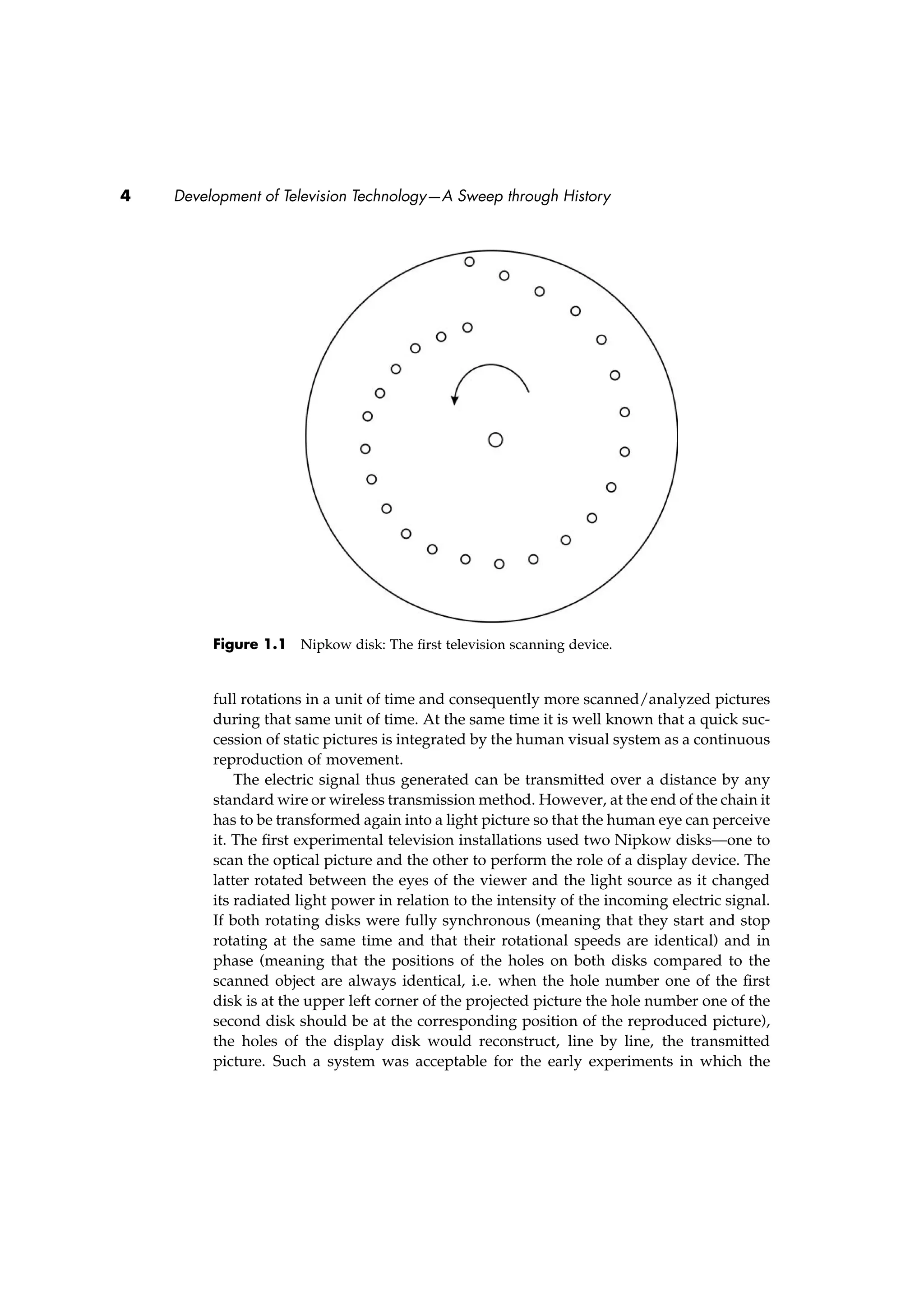


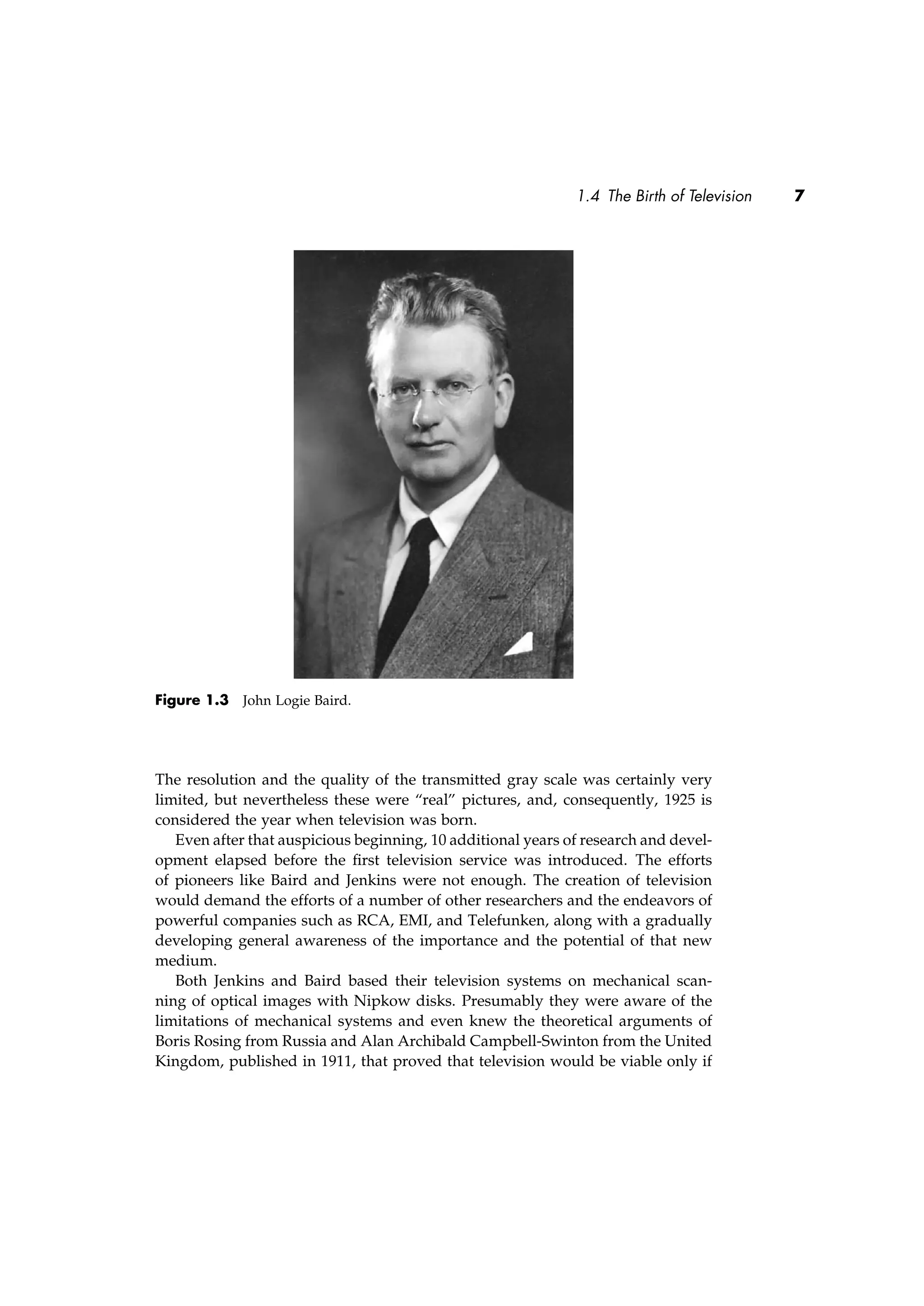


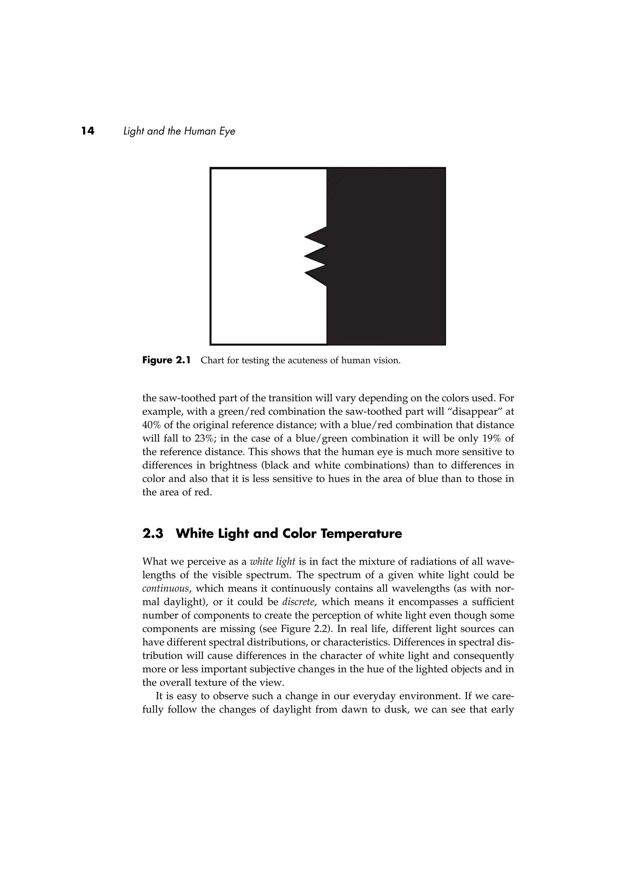


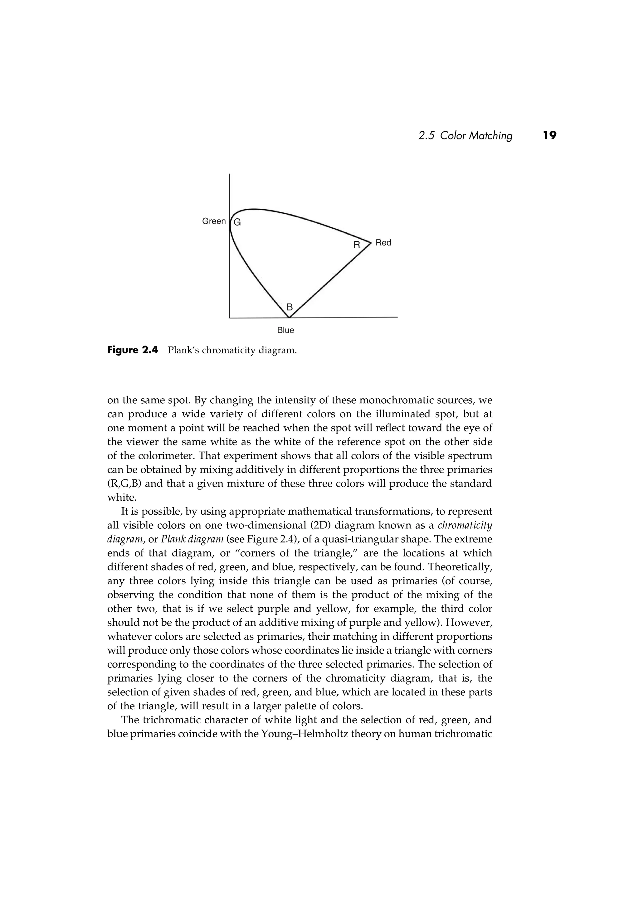


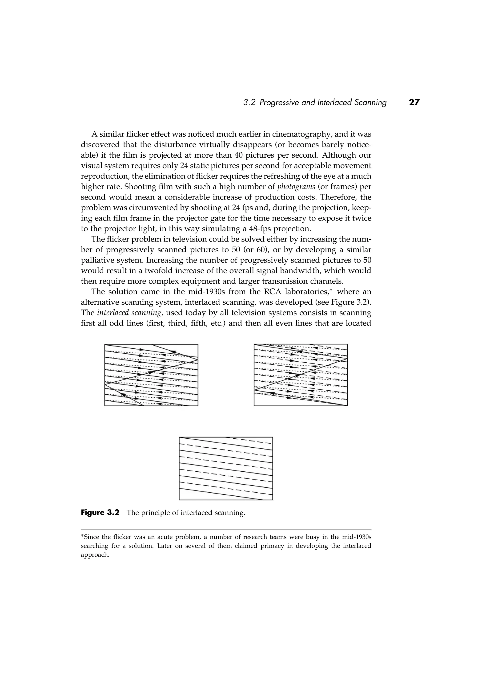
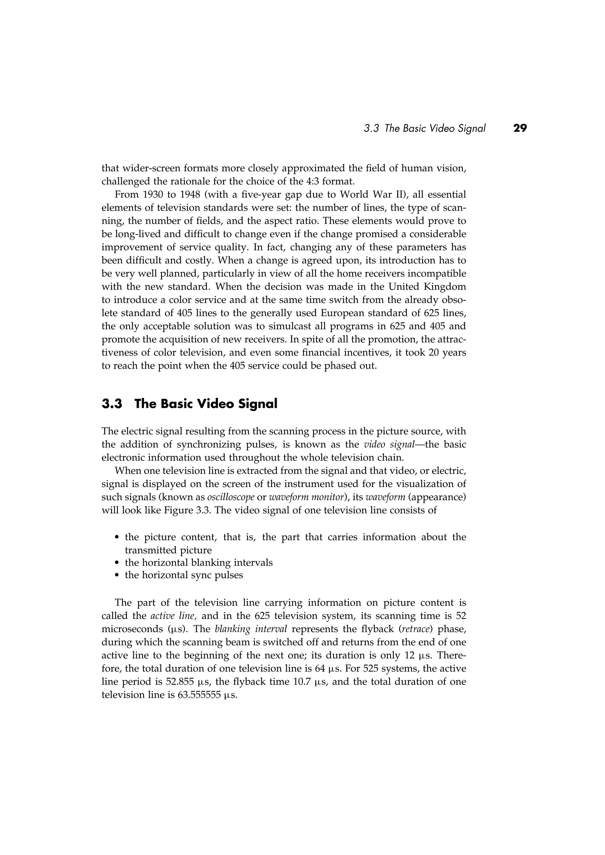
![3.3 The Basic Video Signal 31
The blanking interval carries synchronization but no pictorial information. It
can, therefore, be used for the transmission of additional, or ancillary, information.
For example, the horizontal blanking interval, or more precisely the horizontal
sync pulses, could be used to carry digitally coded sound signals, eliminating the
need to use sound channels in addition to the video channel on international cir-
cuits. Such a system, known as Sound in Syncs (SiS), was widely used in Europe
for analog point-to-point transmissions. With the rapid digitization of produc-
tion plants and transmission channels, the hybrid SiS technique was gradually
replaced by all-digital methods.
On the other hand, the vertical blanking interval (VBI), by its duration, offers
many more possibilities. Since the electron beam in the CRT is switched off
during the vertical blanking interval (vertical retrace period), inserted infor-
mation is not visible nor does it disturb the correct reproduction of television
pictures. However, it can be extracted and made visible by using special-
ized equipment or circuitry. At the same time, the operation of contemporary
receivers is not affected by additional waveforms inserted in the VBI. Conse-
quently, the VBI became a precious resource that could be used for a number of
applications.
Some of those applications are reserved for the internal use of television sta-
tions and transmitting organizations, for example, the transmission of special test
signals that allow the permanent control of the transmission path, the carrying of
standard time and frequency signals, or the carrying of telecommands to studios
and transmitters. Other applications offer an additional service to the end user,
such as
• Program delivery control (PDC). PDC is a set of data that identifies every
program in a station’s schedule and enables the viewer’s home VCR to cor-
rectly record the desired program even if the actual start time differs from the
announced one (the video program system [VPS] is a German development
offering the same features as the PDC).
• Teletext magazines, particularly popular in Europe. Teletext is a way to
send “magazines” consisting of a relatively large number of pages display-
ing different sorts of information, from breaking news and sports results to
service information and advertising. Each page carries 24 rows of 40 char-
acters each; the number of pages is theoretically unlimited, but considering
that the transmission of one page is spread over a number of vertical blank-
ing intervals and that all the pages are transmitted as a sort of carousel, it
is clear that a larger number of pages will mean a longer waiting time for
the display of a selected page. Different forms of teletext are used in other
parts of the world and some of them do not carry magazines but are used
for data transmission.](https://image.slidesharecdn.com/511094-250601090713-aa7d29c4/75/Television-Technology-Demystified-1st-Edition-Aleksandar-Louis-Todorovic-46-2048.jpg)


![a family of them related to crocodiles, viii. 212
Maldive Islands, special terms used with reference to persons of the
blood royal in the, i. 401 n. 3;
virgin sacrificed as bride to a jinnee of the sea in the, ii. 152
sqq.;
disposal of cut hair and nails in the, iii. 274
Male and female, the sticks of the fire-drill regarded by savages as,
ii. 208 sqq., 218, 218 n. 1, 223, 224, 226, 238, 249 sq.;
souls in Chinese philosophy, xi. 221
Male animals not to be killed in houses of absent Malagasy soldiers,
i. 119
—— organ, effigy of, in rites of Dionysus, vii. 12;
effigy of, in Thracian ceremony, vii. 26, 29
Malecki (Maeletius, Menecius), J., on the [pg 358] heathen religion
of the Lithuanians, ii. 366 n. 2
Malekootoos, a Bechuana tribe. See Baperis
Malemut Esquimaux unwilling to tell their names, iii. 328
Malepa, Bantu tribe of the Transvaal, will not taste blood, iii. 241
Maletsunyane, river in Basutoland, ii. 157
Malikolo, in the New Hebrides, heads of infants moulded artificially
in, ii. 298 n. 2
Malkin Tower, witches at the, x. 245
Malko-Tirnovsko, in the district of Adrianople, masquerade at
Carnival at, viii. 331
Mallans of India, their use of a scapegoat in time of cholera, ix. 190](https://image.slidesharecdn.com/511094-250601090713-aa7d29c4/75/Television-Technology-Demystified-1st-Edition-Aleksandar-Louis-Todorovic-56-2048.jpg)
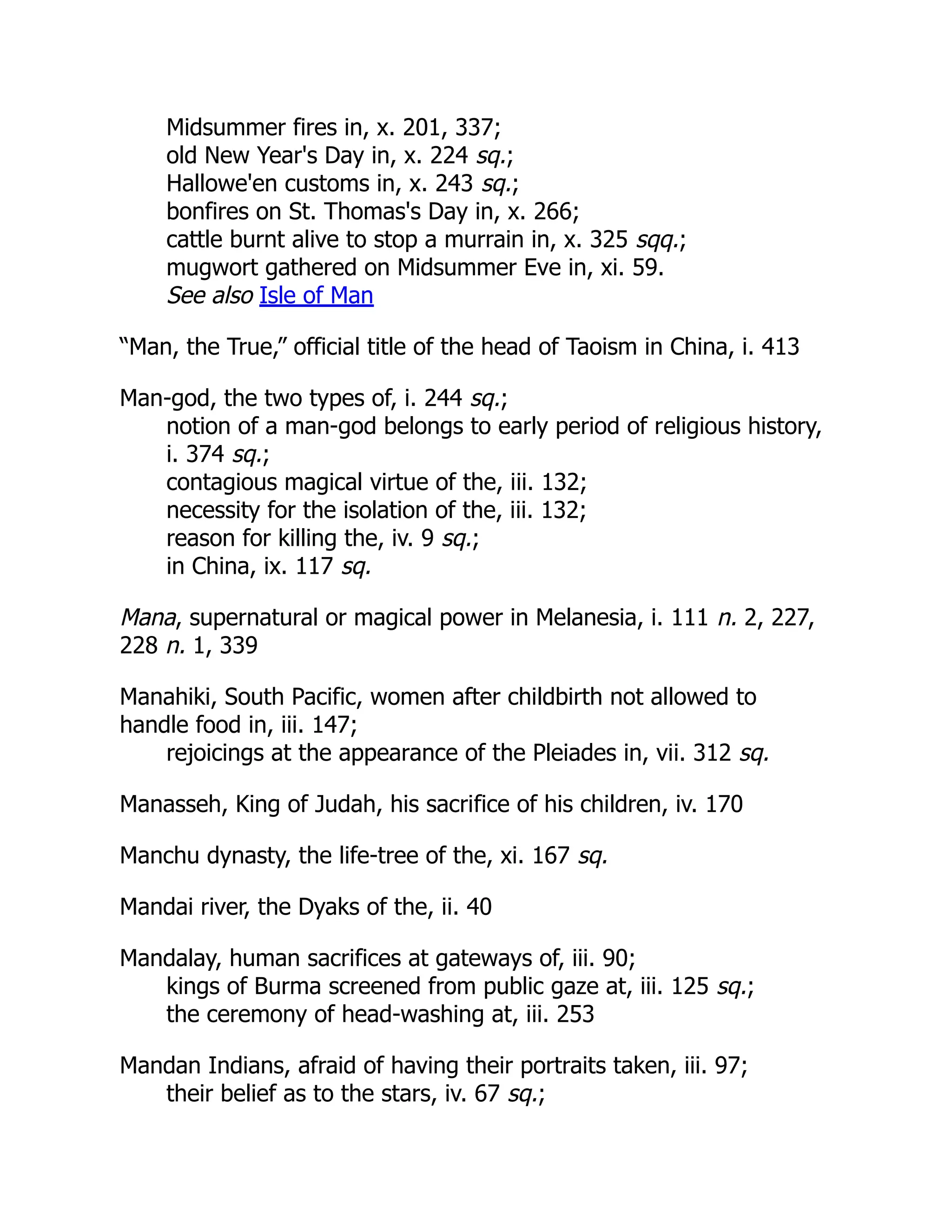
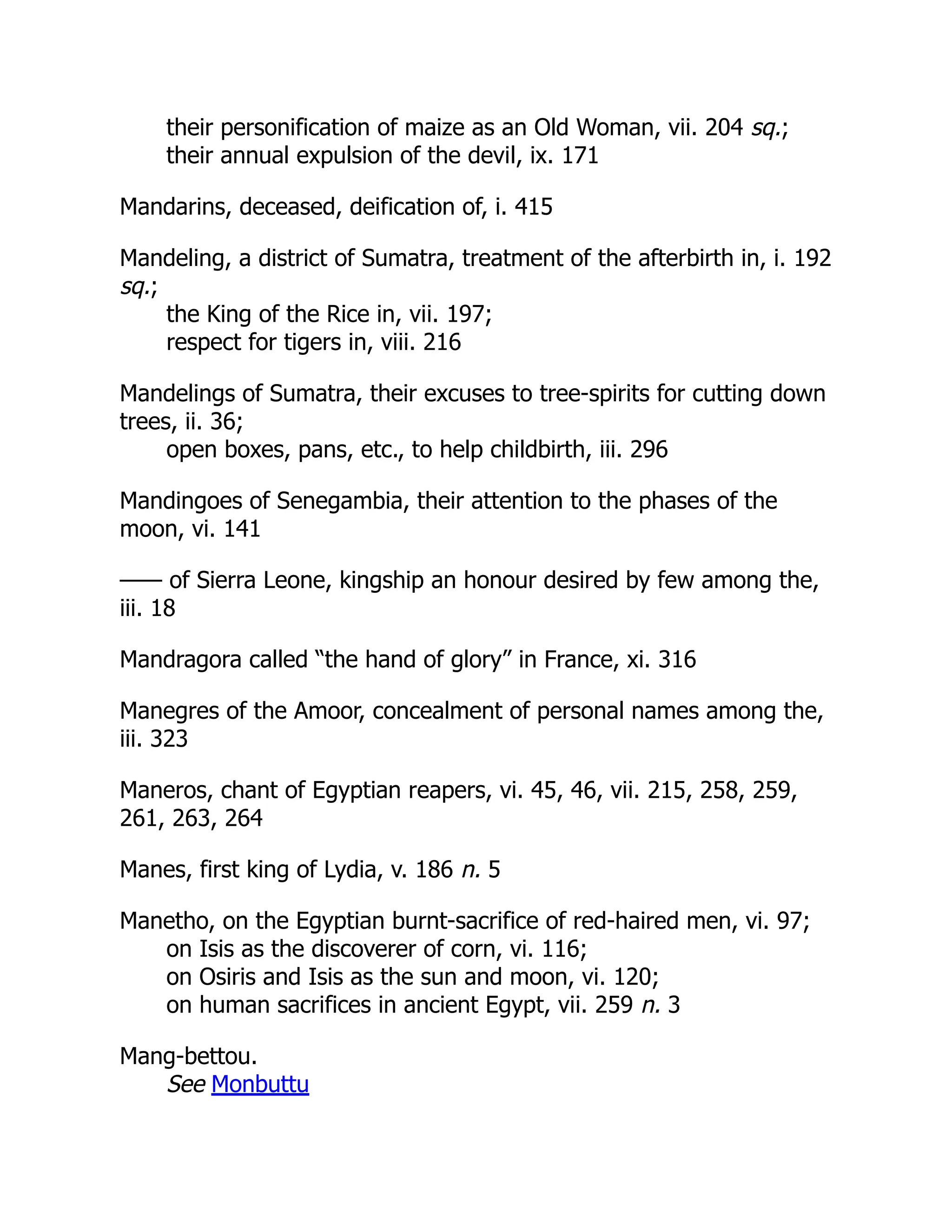
![—— -Shen, Chinese god of agriculture, viii. 11, 12
—— Than, the Warder of the Ox, in Annam, viii. 13 sq.
[pg 359]
Mangaia, Pacific island, priests inspired by gods in, i. 378;
separation of religious and civil authority in, iii. 20
Mangaians, their story of a man whose strength varied with the
length of his shadow, iii. 87;
their preference for a violent death, iv. 10
Mang'anje woman, her external soul in an ivory ornament, xi. 156
Manggarais, the, of Flores, forbidden to utter their own names, iii.
324
Mango married to a tamarind or a jasmine in India, ii. 25
Mango crop, feast of the new, viii. 119
—— -tree, bridegroom tied to, at a Munda marriage, ii. 57;
worshipped by the Nahals, viii. 119;
festival of wild, x. 7 sqq.;
ceremony for the fertilization of the, x. 10
Mani of Chitombe or Jumba, potentate in West Africa, his hair, teeth,
and nails kept after death as a rain-charm, iii. 271
Mania, an ancient Roman bogey, i. 22;
the Mother or Grandmother of Ghosts, viii. 94, 96
Maniae, a kind of loaf, viii. 94
Manichaeans, their theory of earthquakes, v. 197
Manichaeus, the heretic, his death, v. 294 n. 3](https://image.slidesharecdn.com/511094-250601090713-aa7d29c4/75/Television-Technology-Demystified-1st-Edition-Aleksandar-Louis-Todorovic-60-2048.jpg)


![Mannikin, the soul conceived as a, iii. 26 sqq.
Manning, Percy, on May garlands in Hertfordshire, ii. 61 sq.
Man-slayers, purification of, iii. 165 sqq.;
secluded, iii. 165 sqq.;
tabooed, iii. 165 sqq.;
haunted by ghosts of slain, iii. 165 sqq.;
their faces blackened, iii. 169;
their bodies painted, iii. 175, 178, 179, 180, 186 n. 1;
their hair shaved, iii. 175, 177;
taste the blood of their victims, viii. 154 sq.
See also Homicide
Mantinea, Poseidon worshipped at, v. [pg 360] 203 n. 2;
sanctuary of Demeter at, vii. 46 n. 2;
games in honour of Antinous at, vii. 80, 85
Mantineans purify their city by sacrificial victims, iii. 189
Mantis religiosus, a totem in the Duke of York Island, xi. 248 n.
Mantras, the, of the Malay Peninsula, their fear of demons, ix. 88 sq.
Mantras, sacred texts recited as spells by the Brahmans, i. 403 sq.
Manu, Hindoo lawgiver, on the uncleanness of women at
menstruation, x. 95;
on the three births of the Aryan, xi. 276 sq.
See also Manu, the Laws of
Manu, the Laws of, on the effects of a good king's reign, i. 366;
on the divinity of kings and Brahmans, i. 403;
on the rebirth of a father in his son, iv. 188 sq.;
on the transmigration of evil-doers into animals, viii. 298 sq.
Manure, ashes used as, vii. 117](https://image.slidesharecdn.com/511094-250601090713-aa7d29c4/75/Television-Technology-Demystified-1st-Edition-Aleksandar-Louis-Todorovic-63-2048.jpg)
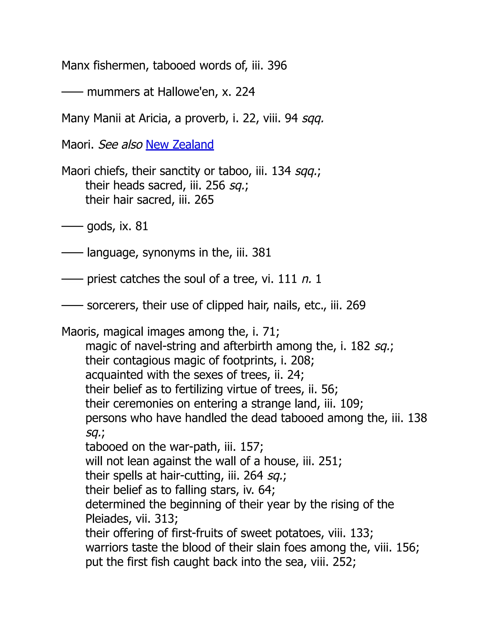
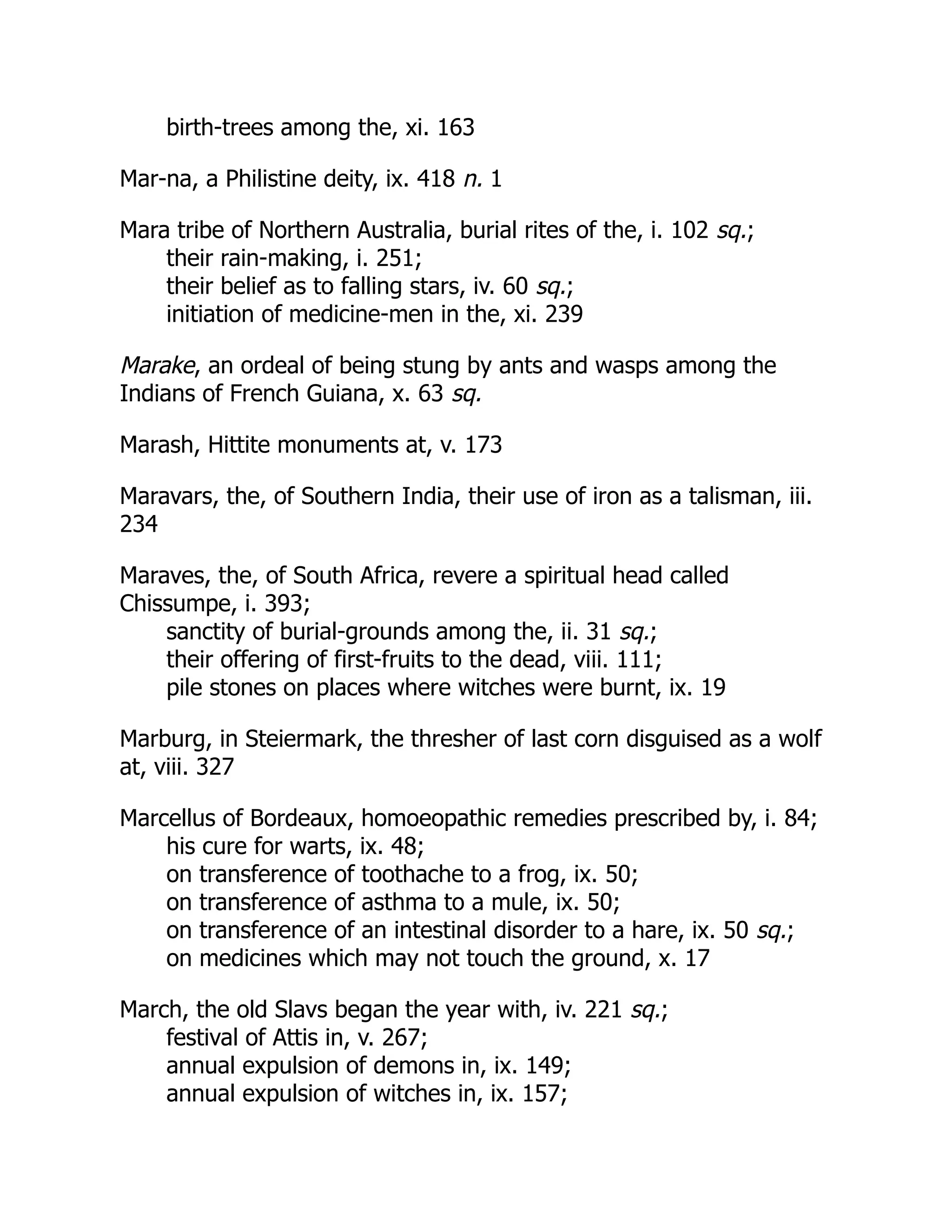

![——, the 1st, sacred fire at Rome annually extinguished on, ii. 267;
custom of “Driving out Death” on, iv. 235;
wooden effigies of swallows carried about the streets on, viii.
322 n.;
bells rung to make the grass grow on, ix. 247;
Roman festival of the Matronalia on, ix. 346
——, the 25th, tradition that Christ was crucified on, v. 306
March moon, woodbine cut in the increase of the, xi. 184
Marco Polo, on beating as a punishment in China, iii. 243 sq.
Mardi Gras, Shrove Tuesday, iv. 227.
See Shrove Tuesday
Marduk or Merodach, chief Babylonian god, ix. 356, 357, 399;
as a magician, i. 240 sq.;
his wives, ii. 130, v. 71; New Year festival of, iv. 110, ix. 356;
his image at Babylon, iv. 113;
as a [pg 361] deliverer from demons, ix. 103;
the votaries of, ix. 372 n. 2
Marduk and Mordecai, ix. 365, 405
—— and Tiamat, iv. 105 sq., 107 sq.
Mare, treatment of the placenta of a, i. 199
—— in foal, last sheaf of corn given to, vii. 160, 162, 168
—— or horse, corn-spirit as, vii. 292 sqq.;](https://image.slidesharecdn.com/511094-250601090713-aa7d29c4/75/Television-Technology-Demystified-1st-Edition-Aleksandar-Louis-Todorovic-67-2048.jpg)

![or real, of human victims, ix. 257 sq.
—— of the Roman gods, vi. 230 sqq.
——, Sacred, ii. 120 sqq.;
of Dionysus with the Queen of Athens, ii. 136 sq., vii. 30 sq.;
of Zeus and Demeter in Eleusinian mysteries, ii. 138, vii. 65
sqq., viii. 9;
of Zeus and Hera, ii. 140 sqq., iv. 91;
of Frey and his wife, ii. 143 sq., iv. 91;
of Roman kings, ii. 172 sq., 192, 193 sq., 318 sq.;
of king and [pg 362] queen, iv. 71;
of gods and goddesses, iv. 73;
of actors disguised as animals, iv. 83;
of priest and priestess as representatives of deities, v. 46 sqq.;
represented in the rock-hewn sculptures at Boghaz-Keui, v. 140;
of Hercules and Hera perhaps celebrated in Cos, vi. 259 n. 4
Marriage of Sky and Earth, v. 282 with n. 2
—— of the Sun and Moon, mythical and dramatic, ii. 146 sq., iv. 71,
73 sq., 78, 87 sq., 90, 92, 105;
of the Sun and Earth, ii. 98 sq., 148, v. 47 sq.
Marriage customs of the Aryan family, vi. 235;
use of children of living parents in, vi. 245 sqq.;
to ensure the birth of boys, vi. 262
—— festival of the gods, i. 129 sqq., ix. 273 n. 1;
festival of all the gods and goddesses in the Date Month, ii. 25
“—— Hollow” at Teltown, iv. 99
Marriages of brothers with sisters in ancient Egypt, vi. 214 sqq.;
their intention to keep the property in the family, vi. 215 sq.](https://image.slidesharecdn.com/511094-250601090713-aa7d29c4/75/Television-Technology-Demystified-1st-Edition-Aleksandar-Louis-Todorovic-71-2048.jpg)


![Martin, Father, on the indifference to human life of a robber caste in
Southern India, iv. 141 sq.
Martin, Rev. John, on annual expulsion of the devil on the Gold
Coast, ix. 132 sq.
Martin, M., on St. Bride's Day in the Hebrides, ii. 94 n. 2;
on forced fire (need-fire) in Scotland, ii. 238, x. 289;
on the cutting of peat in the Hebrides, vi. 138;
on dessil (deiseal), x. 151 n.
Martin of Urzedow, Polish priest, denounced heathen practices of
women on St. John's Eve, x. 177
Martinique, precaution as to spittle in, iii. 289
Martius, C. F. Phil. von, on the political power of medicine-men
among the Indians of Brazil, i. 359
Martyrdom of St. Dasius, ix. 308 sqq.
—— of St. Hippolytus, i. 21
Marwaris of India, Holi festival among the, xi. 2 sq.
Marxberg, the, on the Moselle, fiery wheel rolled down, in Lent, x.
118
Maryborough, in Queensland, custom of the tribes about, as to
women stepping over things, iii. 424;
exposure of [pg 363] first-born children among the tribes about,
iv. 180;
ate men to acquire their virtues, viii. 151
Marzana, goddess of Death, effigy of, in Polish parts of Silesia, iv.
237
Masai of East Africa, power of medicine-men among the, i. 343 sq.;](https://image.slidesharecdn.com/511094-250601090713-aa7d29c4/75/Television-Technology-Demystified-1st-Edition-Aleksandar-Louis-Todorovic-74-2048.jpg)


![“Mass of the Holy Spirit,” i. 231 sq.
[pg 364]
Mass of Saint Sécaire, i. 232 sq.
Massacres for sick kings of Uganda, vi. 226
Massagetae sacrifice horses to the sun, i. 315
Massaya, volcano in Nicaragua, human victims sacrificed to, v. 219
Massebah (plural masseboth), sacred stone or pillar in ancient Israel,
v. 107, 108
Masset, in Queen Charlotte Islands, dances of Haida women at,
while their husbands were away at war, i. 133
Massim, the, of British New Guinea, seclusion of manslayers among,
iii. 169
Masson, Bishop, on Annamite indifference to death, iv. 136 sq.
Mastarna, an Etruscan, ii. 196 n.
Master of the Fish, sacrifices offered by the Tarahumares to the, viii.
252
——, the Heavenly, the head of Taoism in China, i. 413
—— of Life, first-fruits offered by the Arkansas Indians to the, viii.
134
—— of the Revels, ix. 333 sq.
—— of Sorrows at corpse-burning among the Chams, i. 280
Master craftsman regarded as a magician, ix. 81](https://image.slidesharecdn.com/511094-250601090713-aa7d29c4/75/Television-Technology-Demystified-1st-Edition-Aleksandar-Louis-Todorovic-78-2048.jpg)


