This document discusses design patterns for small devices. It begins by introducing design patterns as recurring solutions to software design problems. It notes that the process of building software should be evolutionary, learning from past experiences. The objective is to apply this theory to embedded systems and suggest three design patterns: Hierarchical State, Virtual Component, and LED Error patterns. It then provides details on each of these patterns, including their structure, implementation, applicability and known uses. The Hierarchical State pattern addresses complexity in state machine designs by organizing states hierarchically. The Virtual Component pattern reduces memory usage by loading components on demand. The LED Error pattern standardizes error handling across modules.


![GSG TECHNICAL JOURNAL
Motorola Internal Use Only
DESIGN PATTERNS FOR SMALL DEVICES
Rishi Sharma, Ashok Raja
Abstract: Design patterns are recurring solutions to
software design problems found repeatedly in real-world
software development. It may not always be possible to get
the design right the very first time. One of the major
advances in software development in the past decade has
been the acceptance of the notion that the process of
building a software system should be an evolutionary which
means learning from the past experience and feed backing
the learning to new software systems. Over the period of
time the knowledge of how to design generic, robust, and
scalable software architectures and design has matured.
These reusable solutions to problems have resulted in
considerable savings in terms of costs and time. The
objective of this paper is to imply same theory to embedded
system and suggest three design patterns that help
development and test teams with shorter development and
test cycles.
Index Terms: Design Pattern, small devices, Virtual
Component, Hierarchical State, LED [Light Emitting Diode]
Error and embedded applications.
INTRODUCTION
Working in an embedded environment has its own
challenges. This paper tries to address few of the
following design concerns.
• Memory is precious: Desktop computing has
higher memory capacity (in order of gigabytes).
Getting desktop applications running in
embedded environment where memory is limited
poses challenges to designers as the memory is
limited (in order of megabytes). One example is
trying to synchronize an Outlook address book
with mobile’s contact data.
• Processing speed is limited: Each machine cycle
counts. Use of the composite pattern as a
structural pattern to have a multi level object
hierarchy may add to the processor overhead
preventing the actual code segment to slow.
This impacts the ergonomics of a mobile system.
• Flash/Disk space is a constraint: On a mobile
device the storage is divided between application
space and user space. The physical size of the
date book application on the disk is an example
of application space where as how many meeting
notices a user can store is an example of user
space. Storage needs to be considered part of the
design and new patterns like compression
patterns need to evolve to address such needs.
• Remote Testing of embedded systems: Test
design patterns are to testing what software
design patterns are to programming. There is a
limited support to debug and test in an embedded
environment. Test designs patterns needs to
evolve to support testing of embedded
systems.
Objective:
From our working experience in embedded domain
we have often seen a system divided into small
modules and each module being modeled in form of
state machines. Our analysis shows that in doing so,
one may miss out to pull the commonality of each
module and come up with a generic solution which is
common to each module. This will result in
decreasing the size of a software system and reduced
memory footprint. The objective of this paper is to
highlight the importance of design patterns for small
devices so as to make identification of an appropriate
design pattern as a mandatory activity during the
design phase for embedded systems within Motorola.
We focus on three less common design patterns
which we believe should become part of Motorola’s
design checklist for embedded system architecture
and design. Following three design patterns are
explained with their applicability in the embedded
domain.
1) Hierarchical State Design Pattern
2) Virtual Component Design pattern
3) LED Error Design pattern
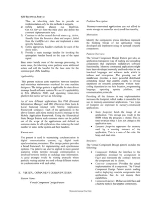
I. HIERARCHICAL STATE DESIGN PATTERN
Pattern Name:
Hierarchical State Design Pattern
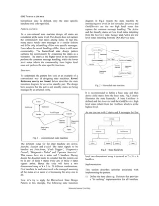
Problem description:
A conventional finite state machine is designed as a
two dimensional array with one dimension as the
state and the other dimension specifying the input
signal to be handled. The state machine determines a
message handler to be called by maintaining the
current state and the received input signal. In a real
life scenario, a task usually has a number of states
along with many different types of input signals. This
leads to complexity in the message handler code as
the number of states increases in the system and the
size of code becomes larger and unmanageable.
Motivation:
The hierarchical state machine design pattern avoids
this problem by recognizing that most states differ in
the handling of only a few messages. When a new](https://image.slidesharecdn.com/389c9d3c-f58e-40b7-b318-0e19e8a9eb70-161107180754/85/Techpaper-3-320.jpg)
![GSG TECHNICAL JOURNAL
Motorola Internal Use Only
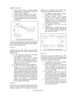
While working on a system prototype, or performing
maintenance in the field, it is difficult to tell that the
system is “alive” - that it has power or the scheduler is
running. Error LED Design Pattern addresses this issue.
Structure:
Every time we implement an embedded system, the first
task we include is one that flashes a “heartbeat” LED.
Wherever possible, this LED stays with the system, right
into production.
This simple technique provides the following key
benefits:
• The development team, the maintenance team,
and, where appropriate, the users, can tell at a
glance that the system has power, and that the
scheduler is operating normally.
• After a little practice, the developer can tell
“intuitively” - by watching the LED – whether
the scheduler is running at the correct rate: if it is
not, it may be that the timers have not been
initialized correctly, or that an incorrect crystal
frequency has been assumed.
• By adding the “Heartbeat” task to the scheduler
array after all other tasks have been included, the
developer can tell immediately if the task array
is large enough to match the needs of the
application.
Implementation:
To implement ERROR LED, a single LED is used to
report error codes to the developer or tester. In most
cases, we like to base the Error LED on a Heartbeat LED
so that, if there are no errors, we see the usual 0.5 Hz
signal. If there is a problem, the display changes, and - by
observing different pulse rates - we can often identify the
cause. Following are the steps for implementation.
Use an error variable, and maintain a list of error codes.
In the event of an error, adjust the output of the ERROR
LED accordingly.
• Initialize the ERROR LED by setting the
appropriate pin to General Purpose Input Output
Register.
• If Error has occurred, change the state from OFF
to ON indicating that an error has occurred.
• LED can be flashed depending upon the
frequency set.
Applicability:
Use of this technique may help to improve system
reliability since it provides the developers of the system
with an indication of its health throughout the
development lifecycle. This provides a low-cost, non-
invasive means of error reporting.
Known uses:
Typical application areas for this type of software
range from passenger cars and aircraft to common
domestic equipment, such as washing machines and
microwave ovens.
CONCLUSIONS:
The Virtual Component Design Pattern allows
developers of standards-based middleware to offer a
large set of functionality to the users while keeping
the static and dynamic memory footprints
proportional to the features actually used.
The Hierarchal State Design Pattern allows for
organizations of states in order to remove duplication
of code and preserving the memory footprint of the
software system.
The LED Error Design Pattern provides a convenient
and economical way to identify major faults in an
embedded system
In future publications, we intent to cover the Wizard
Dialog Design Pattern, the Cascading Menu Design
Pattern, and the Slide Show Design Pattern which
address some of the challenges of the user interface
for small devices.
REFERENCES:
[1] Design Patterns Element of reusable object oriented
software - Eric Richard Ralph John, section 1.3
[2] Code Complete- Steve McConnell, part-1 key
construction decisions, p. 61
[3] EJB Design Patterns - Floyd Marinescu , chapter 9, p.
199
[4] Applied java patterns - Stephen A. Stelting, Olav
Maassen, chapter 3, p.157
[5] Doing Hard Time: Developing Real-Time Systems
with UML, Objects, Frameworks and Patterns-Bruce
Powel Douglass, chapter 7 p.328
ABOUT THE AUTHORS
Rishi Sharma has 8+ years of
experience in the IT industry. He has
been associated with various domains
like NMS, K–Java embedded system,
telecom, high availability, and user
personalized applications.
Ashok Raja has 4+ years of experience
in the IT industry. He has been
associated with various domains
including nuclear power, telecom,
embedded system, and user personalized
applications.](https://image.slidesharecdn.com/389c9d3c-f58e-40b7-b318-0e19e8a9eb70-161107180754/85/Techpaper-8-320.jpg)