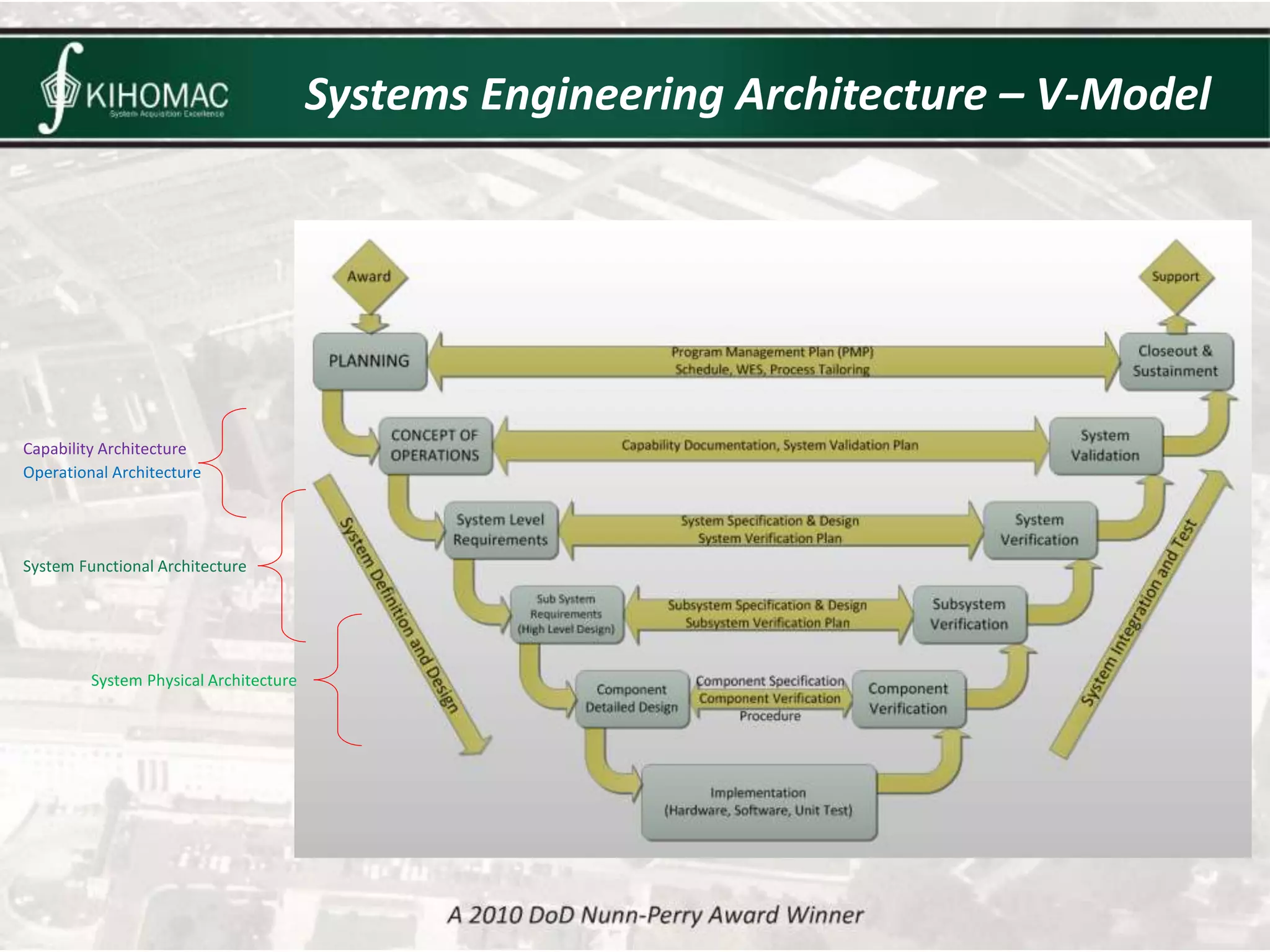
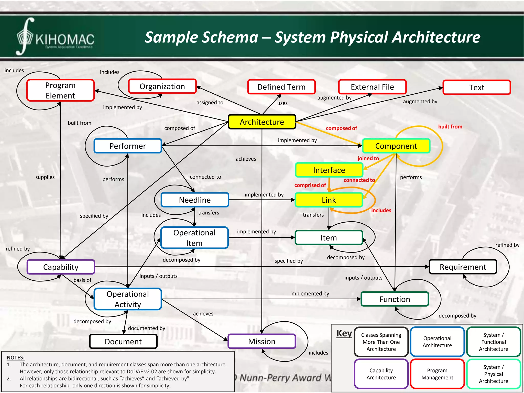
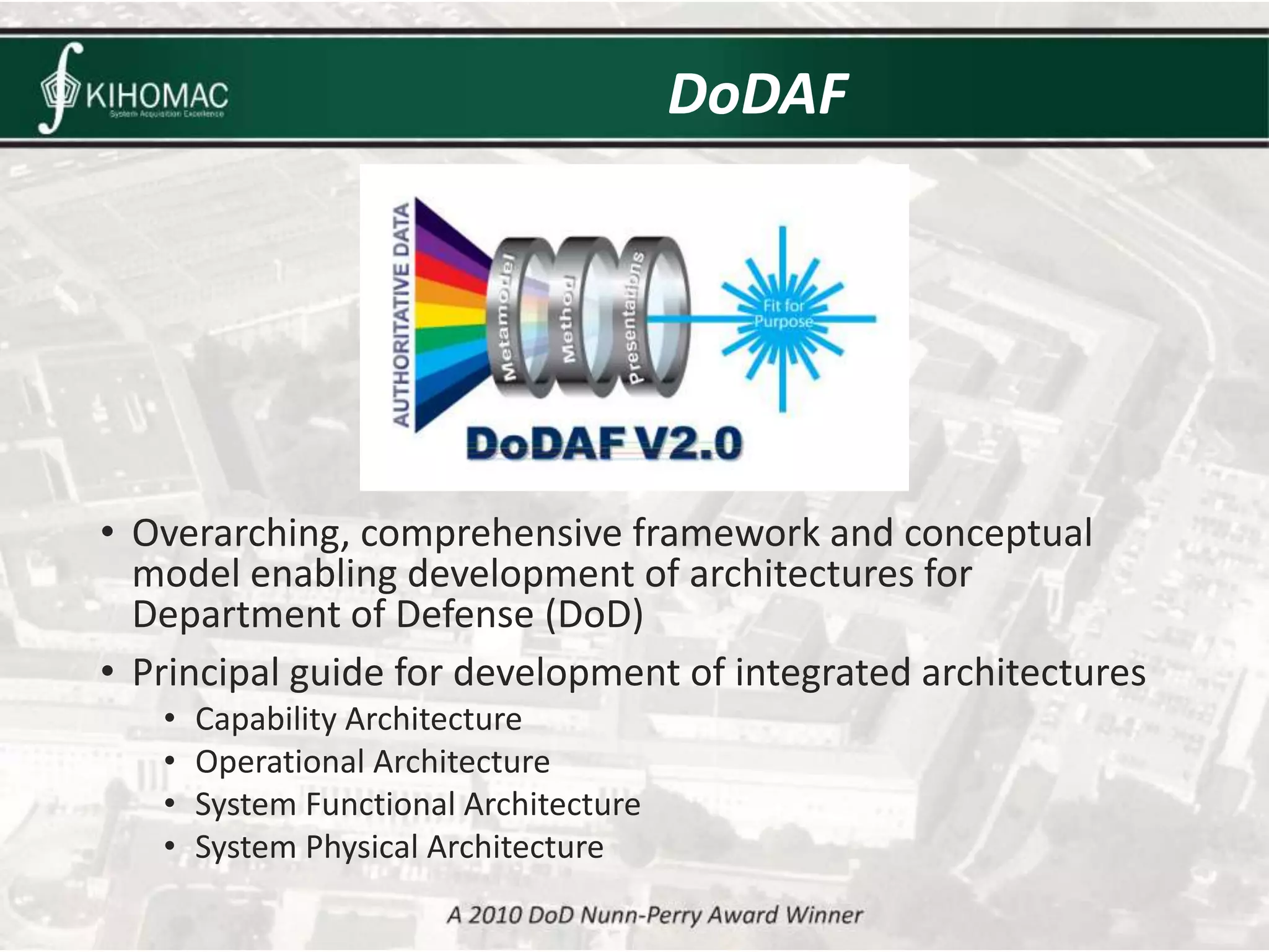
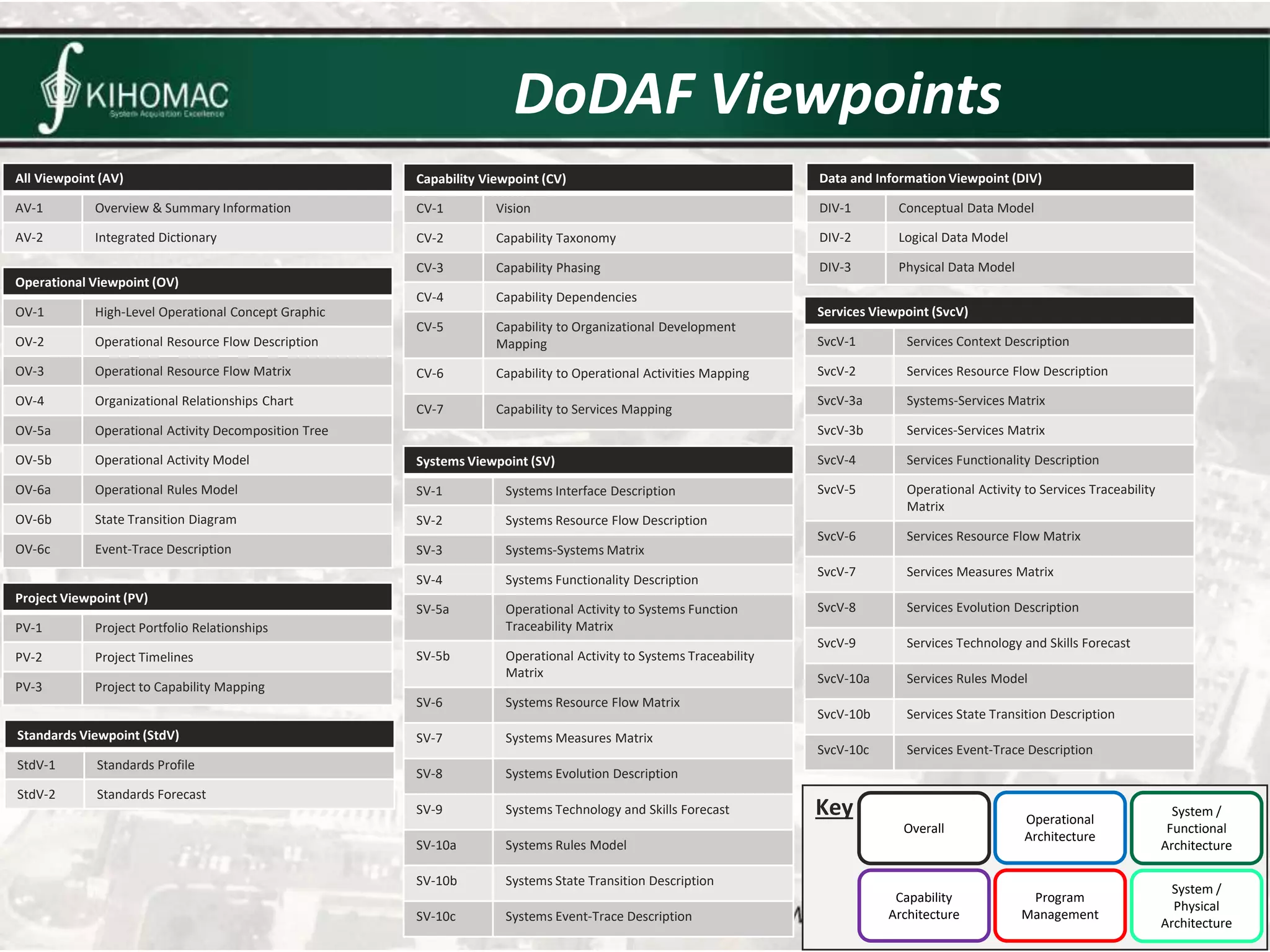
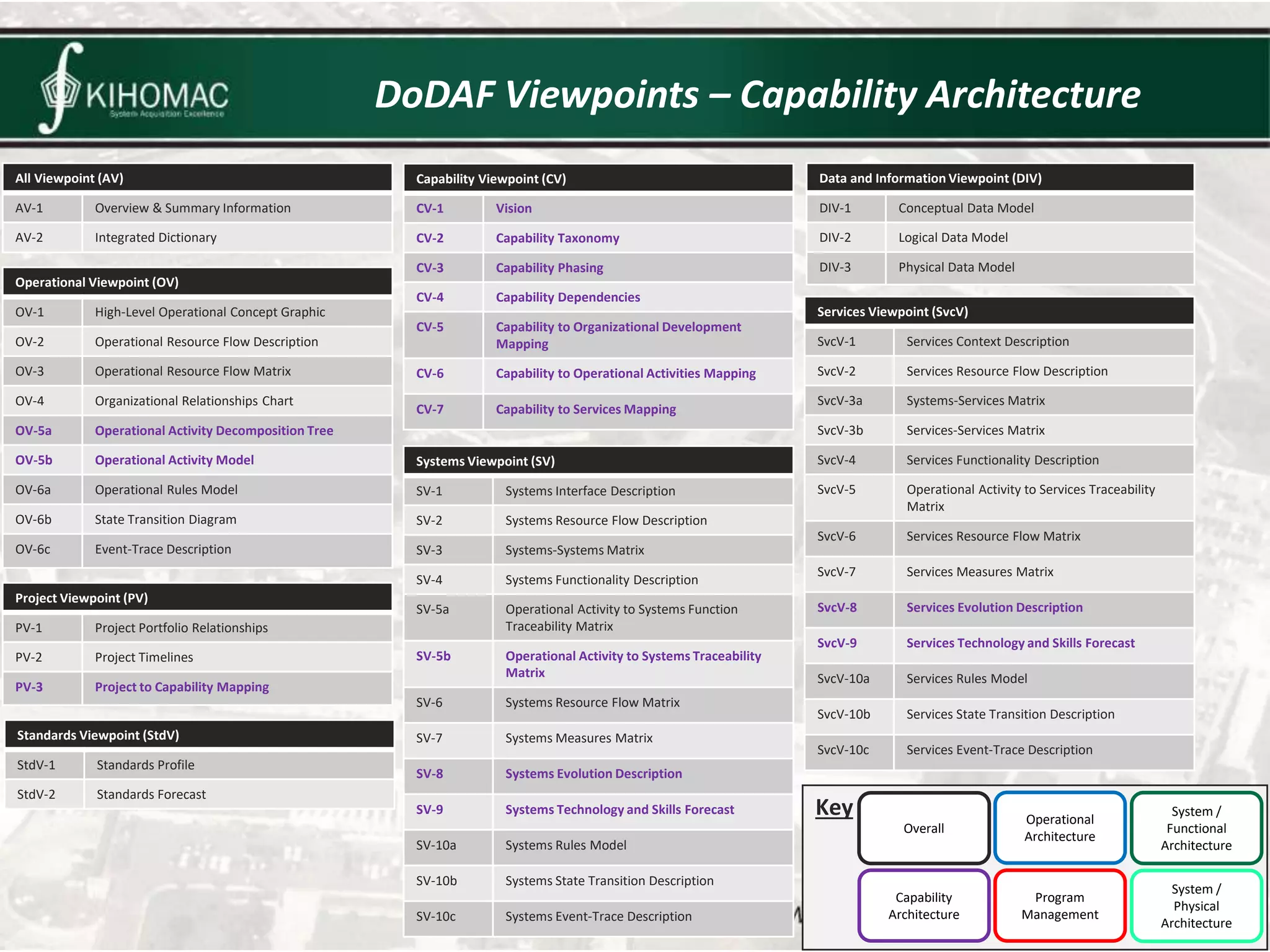
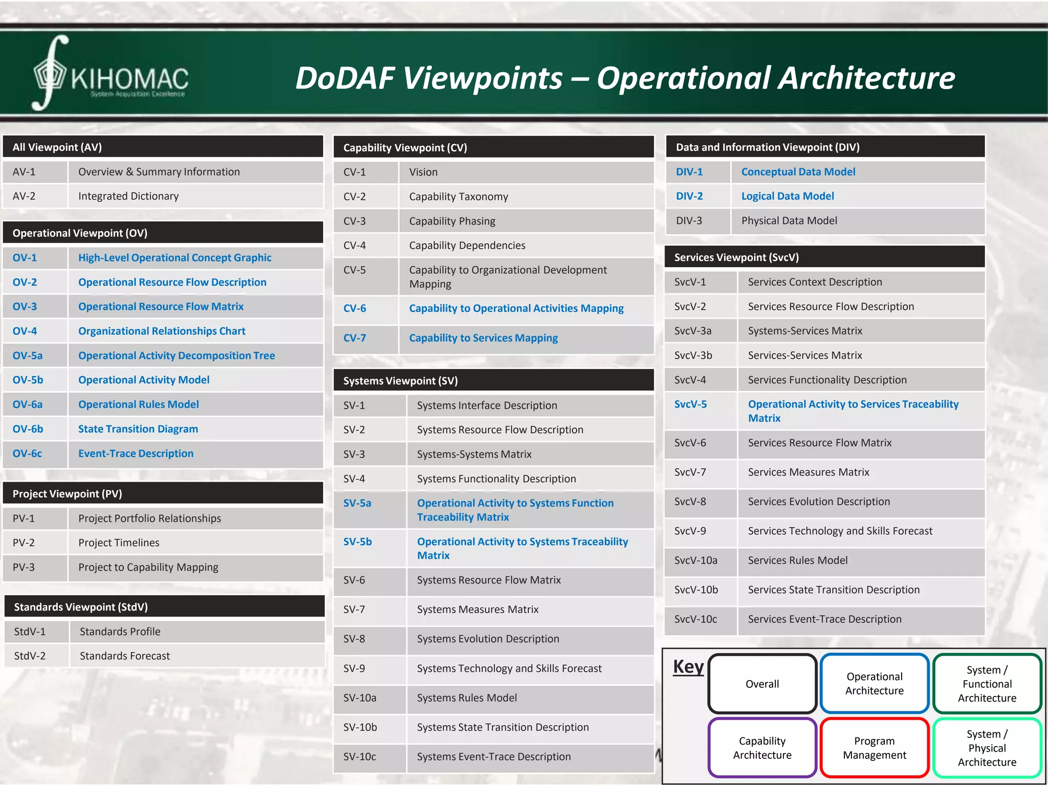
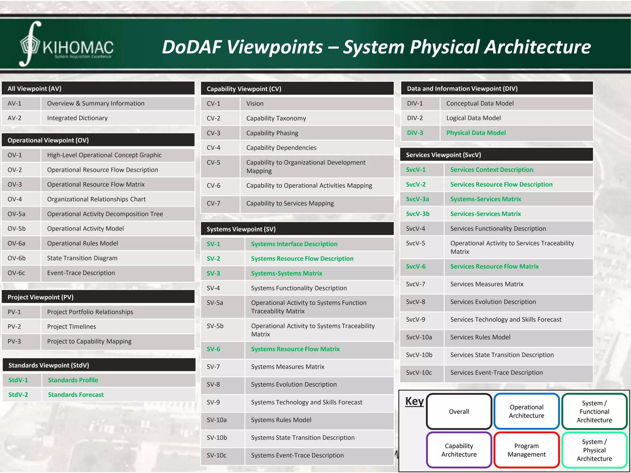
Systems Engineering Architecture
October 13, 2016
1. What is a systems engineering architecture?
2. Discussion about systems engineering
architecture types.
3. Sample Schema (Vitech CORE / GENESYS)
4. Department of Defense Architecture Framework
(DoDAF), Version 2.0
Introduction
Systems Engineering Architecture
Capability
Architecture
Operational
Architecture
System
Functional
Architecture
System
Physical
Architecture
Capability
Requirements
Operational
Requirements
System
Functional
Requirements
System
Physical
Requirements
Systems Engineering Architecture – V-Model
Capability Architecture
Operational Architecture
System Functional Architecture
System Physical Architecture
Capability Architecture
Operational Architecture
System Functional Architecture
System Physical Architecture
Capability Architecture
Capability
Mission • Definition
• A statement that defines a goal or a purpose for your system.
• Specific Applications
• What is the purpose for your system?
• What are the goals of your system?
• Why does your system exist?
• Example
• “The aircraft shall provide close air support by providing firepower in offensive and
defensive operations to destroy, disrupt suppress, fix, or delay enemy forces in
close proximity to friendly forces.”
• Definition
• A quality, ability, or feature that enables your system to be used to achieve one of
its missions.
• Specific Applications
• What does the system need to do?
• What abilities does the system need in order to accomplish one or more of its
missions?
• What are some “capability gaps”, and what is needed to address these?
• Example
• “The aircraft shall have the ability to gather data and obtain required information to
satisfy information needs.”
Operational Architecture
Capability Architecture
Operational Architecture
System Functional Architecture
System Physical Architecture
Operational Architecture
Operational Activity
Performer
Operational Item
Needline
• Definition
• Tasks that use capabilities to achieve missions.
• Specific Applications
• How will the Customer use the system?
• How will the Customer interact with the system?
• Example
• “The pilot shall use a radio to collect communication signals.”
• Definition
• People or organizations that interact with the system.
• Specific Applications
• Who uses the system?
• Who are affected stakeholders?
• Example
• Pilot
• Definition
• Shows how performers interact with each other.
• Specific Applications
• Which performers interact directly with each other?
• How do performers affect each other?
• Example
• Pilot interacts with Air Force Weather Agency
• Definition
• Shows what information is exchanged by performers which engaged in operational activities.
• Specific Applications
• What types of information is exchanged between performers?
• What types of information is needed to do an operational activity?
• Example
• Pilot obtains weather information from the Air Force Weather Agency.
System Functional Architecture
Capability Architecture
Operational Architecture
System Functional Architecture
System Physical Architecture
System Functional Architecture
Item
Function • Definition
• Actions that are performed by the system.
• Specific Applications
• What logical actions does the system need to perform?
• What are some considerations for logical actions (e.g., constraints,
performance requirements, etc.)?
• Example
• “The system shall process RF signals.”
• Definition
• Data that is exchanged between functions.
• Specific Applications
• What analog data is needed?
• What digital data is needed?
• What data formats are needed?
• Example
• “The SATCOM data shall be formatted in accordance with TO 1A-
10C-2-110-1.”
System Physical Architecture
Capability Architecture
Operational Architecture
System Functional Architecture
System Physical Architecture
Interface
Component
Link
• Definition
• Physical components that make up the system.
• Specific Applications
• What components are needed (e.g., processors, radios, cards, wires, sensors, etc.)?
• Example
• “The system shall have an ARC-210 VHF/UHF radio.”
• Definition
• Shows how components interact with each other.
• Specific Applications
• What interface protocols are used?
• Example
• “The system shall use a TIBS interface.”
• Definition
• Shows how components are physically connected.
• Specific Applications
• What wires will be used to connect components?
• Example
• “The system shall use an Ethernet CAT 5 cable.”
Key
Sample Schema
Architecture
composed of
composed of
implemented by
implemented by
joined to
comprised of
transfers
built from
built from
connected to
implemented by
connected to performs
includes
decomposed by
implemented by
transfers
performs
includes
decomposed by specified by
achieves
refined by
inputs / outputs
inputs / outputs
basis of
decomposed by
achieves
includes
decomposed by
assigned to
augmented by
augmented by
includes
supplies
includes
documented by
uses
specified by
implemented by
Organization Defined Term External File Text
Program
Element
Needline
Performer
Interface
Component
Link
Item
Requirement
refined by
Function
Operational
Item
Operational
Activity
Capability
Document Mission
Classes Spanning
More Than One
Architecture
Capability
Architecture
System /
Functional
Architecture
System /
Physical
Architecture
Operational
Architecture
Program
Management
NOTES:
1. The architecture, document, and requirement classes span more than one architecture.
However, only those relationship relevant to DoDAF v2.02 are shown for simplicity.
2. All relationships are bidirectional, such as “achieves” and “achieved by”.
For each relationship, only one direction is shown for simplicity.
Key
Sample Schema – Capability Architecture
Architecture
composed of
composed of
implemented by
implemented by
joined to
comprised of
transfers
built from
built from
connected to
implemented by
connected to performs
includes
decomposed by
implemented by
transfers
performs
includes
decomposed by specified by
achieves
refined by
inputs / outputs
inputs / outputs
basis of
decomposed by
achieves
includes
decomposed by
assigned to
augmented by
augmented by
includes
supplies
includes
documented by
uses
specified by
implemented by
Organization Defined Term External File Text
Program
Element
Needline
Performer
Interface
Component
Link
Item
Requirement
refined by
Function
Operational
Item
Operational
Activity
Capability
Document Mission
Classes Spanning
More Than One
Architecture
Capability
Architecture
System /
Functional
Architecture
System /
Physical
Architecture
Operational
Architecture
Program
Management
NOTES:
1. The architecture, document, and requirement classes span more than one architecture.
However, only those relationship relevant to DoDAF v2.02 are shown for simplicity.
2. All relationships are bidirectional, such as “achieves” and “achieved by”.
For each relationship, only one direction is shown for simplicity.
Key
Sample Schema – Operational Architecture
Architecture
composed of
composed of
implemented by
implemented by
joined to
comprised of
transfers
built from
built from
connected to
implemented by
connected to performs
includes
decomposed by
implemented by
transfers
performs
includes
decomposed by specified by
achieves
refined by
inputs / outputs
inputs / outputs
basis of
decomposed by
achieves
includes
decomposed by
assigned to
augmented by
augmented by
includes
supplies
includes
documented by
uses
specified by
implemented by
Organization Defined Term External File Text
Program
Element
Needline
Performer
Interface
Component
Link
Item
Requirement
refined by
Function
Operational
Item
Operational
Activity
Capability
Document Mission
Classes Spanning
More Than One
Architecture
Capability
Architecture
System /
Functional
Architecture
System /
Physical
Architecture
Operational
Architecture
Program
Management
NOTES:
1. The architecture, document, and requirement classes span more than one architecture.
However, only those relationship relevant to DoDAF v2.02 are shown for simplicity.
2. All relationships are bidirectional, such as “achieves” and “achieved by”.
For each relationship, only one direction is shown for simplicity.
Key
Sample Schema – System Functional Architecture
Architecture
composed of
composed of
implemented by
implemented by
joined to
comprised of
transfers
built from
built from
connected to
implemented by
connected to performs
includes
decomposed by
implemented by
transfers
performs
includes
decomposed by specified by
achieves
refined by
inputs / outputs
inputs / outputs
basis of
decomposed by
achieves
includes
decomposed by
assigned to
augmented by
augmented by
includes
supplies
includes
documented by
uses
specified by
implemented by
Organization Defined Term External File Text
Program
Element
Needline
Performer
Interface
Component
Link
Item
Requirement
refined by
Function
Operational
Item
Operational
Activity
Capability
Document Mission
Classes Spanning
More Than One
Architecture
Capability
Architecture
System /
Functional
Architecture
System /
Physical
Architecture
Operational
Architecture
Program
Management
NOTES:
1. The architecture, document, and requirement classes span more than one architecture.
However, only those relationship relevant to DoDAF v2.02 are shown for simplicity.
2. All relationships are bidirectional, such as “achieves” and “achieved by”.
For each relationship, only one direction is shown for simplicity.
Key
Sample Schema – System Physical Architecture
Architecture
composed of
composed of
implemented by
implemented by
joined to
comprised of
transfers
built from
built from
connected to
implemented by
connected to performs
includes
decomposed by
implemented by
transfers
performs
includes
decomposed by specified by
achieves
refined by
inputs / outputs
inputs / outputs
basis of
decomposed by
achieves
includes
decomposed by
assigned to
augmented by
augmented by
includes
supplies
includes
documented by
uses
specified by
implemented by
Organization Defined Term External File Text
Program
Element
Needline
Performer
Interface
Component
Link
Item
Requirement
refined by
Function
Operational
Item
Operational
Activity
Capability
Document Mission
Classes Spanning
More Than One
Architecture
Capability
Architecture
System /
Functional
Architecture
System /
Physical
Architecture
Operational
Architecture
Program
Management
NOTES:
1. The architecture, document, and requirement classes span more than one architecture.
However, only those relationship relevant to DoDAF v2.02 are shown for simplicity.
2. All relationships are bidirectional, such as “achieves” and “achieved by”.
For each relationship, only one direction is shown for simplicity.
• Overarching, comprehensive framework and conceptual
model enabling development of architectures for
Department of Defense (DoD)
• Principal guide for development of integrated architectures
• Capability Architecture
• Operational Architecture
• System Functional Architecture
• System Physical Architecture
DoDAF
DoDAF: Architecture Methods, Information, &
Presentation Techniques
Architecture Methods
Processes used to build the
architecture
• Model-based Systems Engineering
(MBSE)
• CORE Architecture Definition
Guide
• CORE System Definition Guide
Architecture Information
Architecture elements and
relationships in CORE Database
• Classes
• Element Attributes & Parameters
• Relationships Between Elements
Presentation Techniques
Communication of Architecture
Information in DoDAF Views
• Text Descriptions
• Tables
• Graphical Depictions
http://dodcio.defense.gov/Portals/0/Documents/DODAF/DoDAF%20V2%20-%20Volume%202.pdf
Figure 1.2-1
• All Viewpoint (AV)
• Capability Viewpoint (CV)
• Data and Information Viewpoint (DIV)
• Operational Viewpoint (OV)
• Project Viewpoint (PV)
• Services Viewpoint (SvcV)
• Standards Viewpoint (StdV)
• Systems Viewpoint (SV)
DoDAF Viewpoints
DoDAF Viewpoints
All Viewpoint (AV)
AV-1 Overview & Summary Information
AV-2 Integrated Dictionary
Capability Viewpoint (CV)
CV-1 Vision
CV-2 Capability Taxonomy
CV-3 Capability Phasing
CV-4 Capability Dependencies
CV-5 Capability to Organizational Development
Mapping
CV-6 Capability to Operational Activities Mapping
CV-7 Capability to Services Mapping
Data and Information Viewpoint (DIV)
DIV-1 Conceptual Data Model
DIV-2 Logical Data Model
DIV-3 Physical Data Model
Operational Viewpoint (OV)
OV-1 High-Level Operational Concept Graphic
OV-2 Operational Resource Flow Description
OV-3 Operational Resource Flow Matrix
OV-4 Organizational Relationships Chart
OV-5a Operational Activity Decomposition Tree
OV-5b Operational Activity Model
OV-6a Operational Rules Model
OV-6b State Transition Diagram
OV-6c Event-Trace Description
Project Viewpoint (PV)
PV-1 Project Portfolio Relationships
PV-2 Project Timelines
PV-3 Project to Capability Mapping
Services Viewpoint (SvcV)
SvcV-1 Services Context Description
SvcV-2 Services Resource Flow Description
SvcV-3a Systems-Services Matrix
SvcV-3b Services-Services Matrix
SvcV-4 Services Functionality Description
SvcV-5 Operational Activity to Services Traceability
Matrix
SvcV-6 Services Resource Flow Matrix
SvcV-7 Services Measures Matrix
SvcV-8 Services Evolution Description
SvcV-9 Services Technology and Skills Forecast
SvcV-10a Services Rules Model
SvcV-10b Services State Transition Description
SvcV-10c Services Event-Trace Description
Standards Viewpoint (StdV)
StdV-1 Standards Profile
StdV-2 Standards Forecast
Systems Viewpoint (SV)
SV-1 Systems Interface Description
SV-2 Systems Resource Flow Description
SV-3 Systems-Systems Matrix
SV-4 Systems Functionality Description
SV-5a Operational Activity to Systems Function
Traceability Matrix
SV-5b Operational Activity to Systems Traceability
Matrix
SV-6 Systems Resource Flow Matrix
SV-7 Systems Measures Matrix
SV-8 Systems Evolution Description
SV-9 Systems Technology and Skills Forecast
SV-10a Systems Rules Model
SV-10b Systems State Transition Description
SV-10c Systems Event-Trace Description
Key
Overall
Capability
Architecture
System /
Functional
Architecture
System /
Physical
Architecture
Operational
Architecture
Program
Management
DoDAF Viewpoints - Overall
All Viewpoint (AV)
AV-1 Overview & Summary Information
AV-2 Integrated Dictionary
Capability Viewpoint (CV)
CV-1 Vision
CV-2 Capability Taxonomy
CV-3 Capability Phasing
CV-4 Capability Dependencies
CV-5 Capability to Organizational Development
Mapping
CV-6 Capability to Operational Activities Mapping
CV-7 Capability to Services Mapping
Data and Information Viewpoint (DIV)
DIV-1 Conceptual Data Model
DIV-2 Logical Data Model
DIV-3 Physical Data Model
Operational Viewpoint (OV)
OV-1 High-Level Operational Concept Graphic
OV-2 Operational Resource Flow Description
OV-3 Operational Resource Flow Matrix
OV-4 Organizational Relationships Chart
OV-5a Operational Activity Decomposition Tree
OV-5b Operational Activity Model
OV-6a Operational Rules Model
OV-6b State Transition Diagram
OV-6c Event-Trace Description
Project Viewpoint (PV)
PV-1 Project Portfolio Relationships
PV-2 Project Timelines
PV-3 Project to Capability Mapping
Services Viewpoint (SvcV)
SvcV-1 Services Context Description
SvcV-2 Services Resource Flow Description
SvcV-3a Systems-Services Matrix
SvcV-3b Services-Services Matrix
SvcV-4 Services Functionality Description
SvcV-5 Operational Activity to Services Traceability
Matrix
SvcV-6 Services Resource Flow Matrix
SvcV-7 Services Measures Matrix
SvcV-8 Services Evolution Description
SvcV-9 Services Technology and Skills Forecast
SvcV-10a Services Rules Model
SvcV-10b Services State Transition Description
SvcV-10c Services Event-Trace Description
Standards Viewpoint (StdV)
StdV-1 Standards Profile
StdV-2 Standards Forecast
Systems Viewpoint (SV)
SV-1 Systems Interface Description
SV-2 Systems Resource Flow Description
SV-3 Systems-Systems Matrix
SV-4 Systems Functionality Description
SV-5a Operational Activity to Systems Function
Traceability Matrix
SV-5b Operational Activity to Systems Traceability
Matrix
SV-6 Systems Resource Flow Matrix
SV-7 Systems Measures Matrix
SV-8 Systems Evolution Description
SV-9 Systems Technology and Skills Forecast
SV-10a Systems Rules Model
SV-10b Systems State Transition Description
SV-10c Systems Event-Trace Description
Key
Overall
Capability
Architecture
System /
Functional
Architecture
System /
Physical
Architecture
Operational
Architecture
Program
Management
DoDAF Viewpoints – Capability Architecture
All Viewpoint (AV)
AV-1 Overview & Summary Information
AV-2 Integrated Dictionary
Capability Viewpoint (CV)
CV-1 Vision
CV-2 Capability Taxonomy
CV-3 Capability Phasing
CV-4 Capability Dependencies
CV-5 Capability to Organizational Development
Mapping
CV-6 Capability to Operational Activities Mapping
CV-7 Capability to Services Mapping
Data and Information Viewpoint (DIV)
DIV-1 Conceptual Data Model
DIV-2 Logical Data Model
DIV-3 Physical Data Model
Operational Viewpoint (OV)
OV-1 High-Level Operational Concept Graphic
OV-2 Operational Resource Flow Description
OV-3 Operational Resource Flow Matrix
OV-4 Organizational Relationships Chart
OV-5a Operational Activity Decomposition Tree
OV-5b Operational Activity Model
OV-6a Operational Rules Model
OV-6b State Transition Diagram
OV-6c Event-Trace Description
Project Viewpoint (PV)
PV-1 Project Portfolio Relationships
PV-2 Project Timelines
PV-3 Project to Capability Mapping
Services Viewpoint (SvcV)
SvcV-1 Services Context Description
SvcV-2 Services Resource Flow Description
SvcV-3a Systems-Services Matrix
SvcV-3b Services-Services Matrix
SvcV-4 Services Functionality Description
SvcV-5 Operational Activity to Services Traceability
Matrix
SvcV-6 Services Resource Flow Matrix
SvcV-7 Services Measures Matrix
SvcV-8 Services Evolution Description
SvcV-9 Services Technology and Skills Forecast
SvcV-10a Services Rules Model
SvcV-10b Services State Transition Description
SvcV-10c Services Event-Trace Description
Standards Viewpoint (StdV)
StdV-1 Standards Profile
StdV-2 Standards Forecast
Systems Viewpoint (SV)
SV-1 Systems Interface Description
SV-2 Systems Resource Flow Description
SV-3 Systems-Systems Matrix
SV-4 Systems Functionality Description
SV-5a Operational Activity to Systems Function
Traceability Matrix
SV-5b Operational Activity to Systems Traceability
Matrix
SV-6 Systems Resource Flow Matrix
SV-7 Systems Measures Matrix
SV-8 Systems Evolution Description
SV-9 Systems Technology and Skills Forecast
SV-10a Systems Rules Model
SV-10b Systems State Transition Description
SV-10c Systems Event-Trace Description
Key
Overall
Capability
Architecture
System /
Functional
Architecture
System /
Physical
Architecture
Operational
Architecture
Program
Management
DoDAF Viewpoints – Operational Architecture
All Viewpoint (AV)
AV-1 Overview & Summary Information
AV-2 Integrated Dictionary
Capability Viewpoint (CV)
CV-1 Vision
CV-2 Capability Taxonomy
CV-3 Capability Phasing
CV-4 Capability Dependencies
CV-5 Capability to Organizational Development
Mapping
CV-6 Capability to Operational Activities Mapping
CV-7 Capability to Services Mapping
Data and Information Viewpoint (DIV)
DIV-1 Conceptual Data Model
DIV-2 Logical Data Model
DIV-3 Physical Data Model
Operational Viewpoint (OV)
OV-1 High-Level Operational Concept Graphic
OV-2 Operational Resource Flow Description
OV-3 Operational Resource Flow Matrix
OV-4 Organizational Relationships Chart
OV-5a Operational Activity Decomposition Tree
OV-5b Operational Activity Model
OV-6a Operational Rules Model
OV-6b State Transition Diagram
OV-6c Event-Trace Description
Project Viewpoint (PV)
PV-1 Project Portfolio Relationships
PV-2 Project Timelines
PV-3 Project to Capability Mapping
Services Viewpoint (SvcV)
SvcV-1 Services Context Description
SvcV-2 Services Resource Flow Description
SvcV-3a Systems-Services Matrix
SvcV-3b Services-Services Matrix
SvcV-4 Services Functionality Description
SvcV-5 Operational Activity to Services Traceability
Matrix
SvcV-6 Services Resource Flow Matrix
SvcV-7 Services Measures Matrix
SvcV-8 Services Evolution Description
SvcV-9 Services Technology and Skills Forecast
SvcV-10a Services Rules Model
SvcV-10b Services State Transition Description
SvcV-10c Services Event-Trace Description
Standards Viewpoint (StdV)
StdV-1 Standards Profile
StdV-2 Standards Forecast
Systems Viewpoint (SV)
SV-1 Systems Interface Description
SV-2 Systems Resource Flow Description
SV-3 Systems-Systems Matrix
SV-4 Systems Functionality Description
SV-5a Operational Activity to Systems Function
Traceability Matrix
SV-5b Operational Activity to Systems Traceability
Matrix
SV-6 Systems Resource Flow Matrix
SV-7 Systems Measures Matrix
SV-8 Systems Evolution Description
SV-9 Systems Technology and Skills Forecast
SV-10a Systems Rules Model
SV-10b Systems State Transition Description
SV-10c Systems Event-Trace Description
Key
Overall
Capability
Architecture
System /
Functional
Architecture
System /
Physical
Architecture
Operational
Architecture
Program
Management
DoDAF Viewpoints – System Functional Architecture
All Viewpoint (AV)
AV-1 Overview & Summary Information
AV-2 Integrated Dictionary
Capability Viewpoint (CV)
CV-1 Vision
CV-2 Capability Taxonomy
CV-3 Capability Phasing
CV-4 Capability Dependencies
CV-5 Capability to Organizational Development
Mapping
CV-6 Capability to Operational Activities Mapping
CV-7 Capability to Services Mapping
Data and Information Viewpoint (DIV)
DIV-1 Conceptual Data Model
DIV-2 Logical Data Model
DIV-3 Physical Data Model
Operational Viewpoint (OV)
OV-1 High-Level Operational Concept Graphic
OV-2 Operational Resource Flow Description
OV-3 Operational Resource Flow Matrix
OV-4 Organizational Relationships Chart
OV-5a Operational Activity Decomposition Tree
OV-5b Operational Activity Model
OV-6a Operational Rules Model
OV-6b State Transition Diagram
OV-6c Event-Trace Description
Project Viewpoint (PV)
PV-1 Project Portfolio Relationships
PV-2 Project Timelines
PV-3 Project to Capability Mapping
Services Viewpoint (SvcV)
SvcV-1 Services Context Description
SvcV-2 Services Resource Flow Description
SvcV-3a Systems-Services Matrix
SvcV-3b Services-Services Matrix
SvcV-4 Services Functionality Description
SvcV-5 Operational Activity to Services Traceability
Matrix
SvcV-6 Services Resource Flow Matrix
SvcV-7 Services Measures Matrix
SvcV-8 Services Evolution Description
SvcV-9 Services Technology and Skills Forecast
SvcV-10a Services Rules Model
SvcV-10b Services State Transition Description
SvcV-10c Services Event-Trace Description
Standards Viewpoint (StdV)
StdV-1 Standards Profile
StdV-2 Standards Forecast
Systems Viewpoint (SV)
SV-1 Systems Interface Description
SV-2 Systems Resource Flow Description
SV-3 Systems-Systems Matrix
SV-4 Systems Functionality Description
SV-5a Operational Activity to Systems Function
Traceability Matrix
SV-5b Operational Activity to Systems Traceability
Matrix
SV-6 Systems Resource Flow Matrix
SV-7 Systems Measures Matrix
SV-8 Systems Evolution Description
SV-9 Systems Technology and Skills Forecast
SV-10a Systems Rules Model
SV-10b Systems State Transition Description
SV-10c Systems Event-Trace Description
Key
Overall
Capability
Architecture
System /
Functional
Architecture
System /
Physical
Architecture
Operational
Architecture
Program
Management
DoDAF Viewpoints – System Physical Architecture
All Viewpoint (AV)
AV-1 Overview & Summary Information
AV-2 Integrated Dictionary
Capability Viewpoint (CV)
CV-1 Vision
CV-2 Capability Taxonomy
CV-3 Capability Phasing
CV-4 Capability Dependencies
CV-5 Capability to Organizational Development
Mapping
CV-6 Capability to Operational Activities Mapping
CV-7 Capability to Services Mapping
Data and Information Viewpoint (DIV)
DIV-1 Conceptual Data Model
DIV-2 Logical Data Model
DIV-3 Physical Data Model
Operational Viewpoint (OV)
OV-1 High-Level Operational Concept Graphic
OV-2 Operational Resource Flow Description
OV-3 Operational Resource Flow Matrix
OV-4 Organizational Relationships Chart
OV-5a Operational Activity Decomposition Tree
OV-5b Operational Activity Model
OV-6a Operational Rules Model
OV-6b State Transition Diagram
OV-6c Event-Trace Description
Project Viewpoint (PV)
PV-1 Project Portfolio Relationships
PV-2 Project Timelines
PV-3 Project to Capability Mapping
Services Viewpoint (SvcV)
SvcV-1 Services Context Description
SvcV-2 Services Resource Flow Description
SvcV-3a Systems-Services Matrix
SvcV-3b Services-Services Matrix
SvcV-4 Services Functionality Description
SvcV-5 Operational Activity to Services Traceability
Matrix
SvcV-6 Services Resource Flow Matrix
SvcV-7 Services Measures Matrix
SvcV-8 Services Evolution Description
SvcV-9 Services Technology and Skills Forecast
SvcV-10a Services Rules Model
SvcV-10b Services State Transition Description
SvcV-10c Services Event-Trace Description
Standards Viewpoint (StdV)
StdV-1 Standards Profile
StdV-2 Standards Forecast
Systems Viewpoint (SV)
SV-1 Systems Interface Description
SV-2 Systems Resource Flow Description
SV-3 Systems-Systems Matrix
SV-4 Systems Functionality Description
SV-5a Operational Activity to Systems Function
Traceability Matrix
SV-5b Operational Activity to Systems Traceability
Matrix
SV-6 Systems Resource Flow Matrix
SV-7 Systems Measures Matrix
SV-8 Systems Evolution Description
SV-9 Systems Technology and Skills Forecast
SV-10a Systems Rules Model
SV-10b Systems State Transition Description
SV-10c Systems Event-Trace Description
Key
Overall
Capability
Architecture
System /
Functional
Architecture
System /
Physical
Architecture
Operational
Architecture
Program
Management
DoDAF Viewpoints – Program Management
All Viewpoint (AV)
AV-1 Overview & Summary Information
AV-2 Integrated Dictionary
Capability Viewpoint (CV)
CV-1 Vision
CV-2 Capability Taxonomy
CV-3 Capability Phasing
CV-4 Capability Dependencies
CV-5 Capability to Organizational Development
Mapping
CV-6 Capability to Operational Activities Mapping
CV-7 Capability to Services Mapping
Data and Information Viewpoint (DIV)
DIV-1 Conceptual Data Model
DIV-2 Logical Data Model
DIV-3 Physical Data Model
Operational Viewpoint (OV)
OV-1 High-Level Operational Concept Graphic
OV-2 Operational Resource Flow Description
OV-3 Operational Resource Flow Matrix
OV-4 Organizational Relationships Chart
OV-5a Operational Activity Decomposition Tree
OV-5b Operational Activity Model
OV-6a Operational Rules Model
OV-6b State Transition Diagram
OV-6c Event-Trace Description
Project Viewpoint (PV)
PV-1 Project Portfolio Relationships
PV-2 Project Timelines
PV-3 Project to Capability Mapping
Services Viewpoint (SvcV)
SvcV-1 Services Context Description
SvcV-2 Services Resource Flow Description
SvcV-3a Systems-Services Matrix
SvcV-3b Services-Services Matrix
SvcV-4 Services Functionality Description
SvcV-5 Operational Activity to Services Traceability
Matrix
SvcV-6 Services Resource Flow Matrix
SvcV-7 Services Measures Matrix
SvcV-8 Services Evolution Description
SvcV-9 Services Technology and Skills Forecast
SvcV-10a Services Rules Model
SvcV-10b Services State Transition Description
SvcV-10c Services Event-Trace Description
Standards Viewpoint (StdV)
StdV-1 Standards Profile
StdV-2 Standards Forecast
Systems Viewpoint (SV)
SV-1 Systems Interface Description
SV-2 Systems Resource Flow Description
SV-3 Systems-Systems Matrix
SV-4 Systems Functionality Description
SV-5a Operational Activity to Systems Function
Traceability Matrix
SV-5b Operational Activity to Systems Traceability
Matrix
SV-6 Systems Resource Flow Matrix
SV-7 Systems Measures Matrix
SV-8 Systems Evolution Description
SV-9 Systems Technology and Skills Forecast
SV-10a Systems Rules Model
SV-10b Systems State Transition Description
SV-10c Systems Event-Trace Description
Key
Overall
Capability
Architecture
System /
Functional
Architecture
System /
Physical
Architecture
Operational
Architecture
Program
Management
• Systems Engineering Architecture Types
• Capability Architecture
• Operational Architecture
• System Functional Architecture
• System Physical Architecture
• Sample Schema
• DoDAF
Conclusion
Acronym List
Acronym Definition
DoD Department of Defense
DoDAF Department of Defense Architecture Framework
DoDCIO Department of Defense Chief Information Officer
INCOSE International Council on Systems Engineering
Paul White
Senior Systems Engineer
Kihomac, Inc.
Layton, Utah
• E-mail: Paul.White@kihomac.com
• Phone: 1-801-593-7088 x179
Contact Information

Systems Engineering Architecture - Vitech.pptx

  • 1.
  • 2.
    1. What isa systems engineering architecture? 2. Discussion about systems engineering architecture types. 3. Sample Schema (Vitech CORE / GENESYS) 4. Department of Defense Architecture Framework (DoDAF), Version 2.0 Introduction
  • 3.
  • 4.
    Systems Engineering Architecture SystemsEngineering Architecture Capability Architecture Operational Architecture System Functional Architecture System Physical Architecture Capability Requirements Operational Requirements System Functional Requirements System Physical Requirements
  • 5.
    Systems Engineering Architecture– V-Model Capability Architecture Operational Architecture System Functional Architecture System Physical Architecture
  • 6.
    Capability Architecture Capability Architecture OperationalArchitecture System Functional Architecture System Physical Architecture
  • 7.
    Capability Architecture Capability Mission •Definition • A statement that defines a goal or a purpose for your system. • Specific Applications • What is the purpose for your system? • What are the goals of your system? • Why does your system exist? • Example • “The aircraft shall provide close air support by providing firepower in offensive and defensive operations to destroy, disrupt suppress, fix, or delay enemy forces in close proximity to friendly forces.” • Definition • A quality, ability, or feature that enables your system to be used to achieve one of its missions. • Specific Applications • What does the system need to do? • What abilities does the system need in order to accomplish one or more of its missions? • What are some “capability gaps”, and what is needed to address these? • Example • “The aircraft shall have the ability to gather data and obtain required information to satisfy information needs.”
  • 8.
    Operational Architecture Capability Architecture OperationalArchitecture System Functional Architecture System Physical Architecture
  • 9.
    Operational Architecture Operational Activity Performer OperationalItem Needline • Definition • Tasks that use capabilities to achieve missions. • Specific Applications • How will the Customer use the system? • How will the Customer interact with the system? • Example • “The pilot shall use a radio to collect communication signals.” • Definition • People or organizations that interact with the system. • Specific Applications • Who uses the system? • Who are affected stakeholders? • Example • Pilot • Definition • Shows how performers interact with each other. • Specific Applications • Which performers interact directly with each other? • How do performers affect each other? • Example • Pilot interacts with Air Force Weather Agency • Definition • Shows what information is exchanged by performers which engaged in operational activities. • Specific Applications • What types of information is exchanged between performers? • What types of information is needed to do an operational activity? • Example • Pilot obtains weather information from the Air Force Weather Agency.
  • 10.
    System Functional Architecture CapabilityArchitecture Operational Architecture System Functional Architecture System Physical Architecture
  • 11.
    System Functional Architecture Item Function• Definition • Actions that are performed by the system. • Specific Applications • What logical actions does the system need to perform? • What are some considerations for logical actions (e.g., constraints, performance requirements, etc.)? • Example • “The system shall process RF signals.” • Definition • Data that is exchanged between functions. • Specific Applications • What analog data is needed? • What digital data is needed? • What data formats are needed? • Example • “The SATCOM data shall be formatted in accordance with TO 1A- 10C-2-110-1.”
  • 12.
    System Physical Architecture CapabilityArchitecture Operational Architecture System Functional Architecture System Physical Architecture
  • 13.
    System Physical Architecture Interface Component Link •Definition • Physical components that make up the system. • Specific Applications • What components are needed (e.g., processors, radios, cards, wires, sensors, etc.)? • Example • “The system shall have an ARC-210 VHF/UHF radio.” • Definition • Shows how components interact with each other. • Specific Applications • What interface protocols are used? • Example • “The system shall use a TIBS interface.” • Definition • Shows how components are physically connected. • Specific Applications • What wires will be used to connect components? • Example • “The system shall use an Ethernet CAT 5 cable.”
  • 14.
    Key Sample Schema Architecture composed of composedof implemented by implemented by joined to comprised of transfers built from built from connected to implemented by connected to performs includes decomposed by implemented by transfers performs includes decomposed by specified by achieves refined by inputs / outputs inputs / outputs basis of decomposed by achieves includes decomposed by assigned to augmented by augmented by includes supplies includes documented by uses specified by implemented by Organization Defined Term External File Text Program Element Needline Performer Interface Component Link Item Requirement refined by Function Operational Item Operational Activity Capability Document Mission Classes Spanning More Than One Architecture Capability Architecture System / Functional Architecture System / Physical Architecture Operational Architecture Program Management NOTES: 1. The architecture, document, and requirement classes span more than one architecture. However, only those relationship relevant to DoDAF v2.02 are shown for simplicity. 2. All relationships are bidirectional, such as “achieves” and “achieved by”. For each relationship, only one direction is shown for simplicity.
  • 15.
    Key Sample Schema –Capability Architecture Architecture composed of composed of implemented by implemented by joined to comprised of transfers built from built from connected to implemented by connected to performs includes decomposed by implemented by transfers performs includes decomposed by specified by achieves refined by inputs / outputs inputs / outputs basis of decomposed by achieves includes decomposed by assigned to augmented by augmented by includes supplies includes documented by uses specified by implemented by Organization Defined Term External File Text Program Element Needline Performer Interface Component Link Item Requirement refined by Function Operational Item Operational Activity Capability Document Mission Classes Spanning More Than One Architecture Capability Architecture System / Functional Architecture System / Physical Architecture Operational Architecture Program Management NOTES: 1. The architecture, document, and requirement classes span more than one architecture. However, only those relationship relevant to DoDAF v2.02 are shown for simplicity. 2. All relationships are bidirectional, such as “achieves” and “achieved by”. For each relationship, only one direction is shown for simplicity.
  • 16.
    Key Sample Schema –Operational Architecture Architecture composed of composed of implemented by implemented by joined to comprised of transfers built from built from connected to implemented by connected to performs includes decomposed by implemented by transfers performs includes decomposed by specified by achieves refined by inputs / outputs inputs / outputs basis of decomposed by achieves includes decomposed by assigned to augmented by augmented by includes supplies includes documented by uses specified by implemented by Organization Defined Term External File Text Program Element Needline Performer Interface Component Link Item Requirement refined by Function Operational Item Operational Activity Capability Document Mission Classes Spanning More Than One Architecture Capability Architecture System / Functional Architecture System / Physical Architecture Operational Architecture Program Management NOTES: 1. The architecture, document, and requirement classes span more than one architecture. However, only those relationship relevant to DoDAF v2.02 are shown for simplicity. 2. All relationships are bidirectional, such as “achieves” and “achieved by”. For each relationship, only one direction is shown for simplicity.
  • 17.
    Key Sample Schema –System Functional Architecture Architecture composed of composed of implemented by implemented by joined to comprised of transfers built from built from connected to implemented by connected to performs includes decomposed by implemented by transfers performs includes decomposed by specified by achieves refined by inputs / outputs inputs / outputs basis of decomposed by achieves includes decomposed by assigned to augmented by augmented by includes supplies includes documented by uses specified by implemented by Organization Defined Term External File Text Program Element Needline Performer Interface Component Link Item Requirement refined by Function Operational Item Operational Activity Capability Document Mission Classes Spanning More Than One Architecture Capability Architecture System / Functional Architecture System / Physical Architecture Operational Architecture Program Management NOTES: 1. The architecture, document, and requirement classes span more than one architecture. However, only those relationship relevant to DoDAF v2.02 are shown for simplicity. 2. All relationships are bidirectional, such as “achieves” and “achieved by”. For each relationship, only one direction is shown for simplicity.
  • 18.
    Key Sample Schema –System Physical Architecture Architecture composed of composed of implemented by implemented by joined to comprised of transfers built from built from connected to implemented by connected to performs includes decomposed by implemented by transfers performs includes decomposed by specified by achieves refined by inputs / outputs inputs / outputs basis of decomposed by achieves includes decomposed by assigned to augmented by augmented by includes supplies includes documented by uses specified by implemented by Organization Defined Term External File Text Program Element Needline Performer Interface Component Link Item Requirement refined by Function Operational Item Operational Activity Capability Document Mission Classes Spanning More Than One Architecture Capability Architecture System / Functional Architecture System / Physical Architecture Operational Architecture Program Management NOTES: 1. The architecture, document, and requirement classes span more than one architecture. However, only those relationship relevant to DoDAF v2.02 are shown for simplicity. 2. All relationships are bidirectional, such as “achieves” and “achieved by”. For each relationship, only one direction is shown for simplicity.
  • 19.
    • Overarching, comprehensiveframework and conceptual model enabling development of architectures for Department of Defense (DoD) • Principal guide for development of integrated architectures • Capability Architecture • Operational Architecture • System Functional Architecture • System Physical Architecture DoDAF
  • 20.
    DoDAF: Architecture Methods,Information, & Presentation Techniques Architecture Methods Processes used to build the architecture • Model-based Systems Engineering (MBSE) • CORE Architecture Definition Guide • CORE System Definition Guide Architecture Information Architecture elements and relationships in CORE Database • Classes • Element Attributes & Parameters • Relationships Between Elements Presentation Techniques Communication of Architecture Information in DoDAF Views • Text Descriptions • Tables • Graphical Depictions http://dodcio.defense.gov/Portals/0/Documents/DODAF/DoDAF%20V2%20-%20Volume%202.pdf Figure 1.2-1
  • 21.
    • All Viewpoint(AV) • Capability Viewpoint (CV) • Data and Information Viewpoint (DIV) • Operational Viewpoint (OV) • Project Viewpoint (PV) • Services Viewpoint (SvcV) • Standards Viewpoint (StdV) • Systems Viewpoint (SV) DoDAF Viewpoints
  • 22.
    DoDAF Viewpoints All Viewpoint(AV) AV-1 Overview & Summary Information AV-2 Integrated Dictionary Capability Viewpoint (CV) CV-1 Vision CV-2 Capability Taxonomy CV-3 Capability Phasing CV-4 Capability Dependencies CV-5 Capability to Organizational Development Mapping CV-6 Capability to Operational Activities Mapping CV-7 Capability to Services Mapping Data and Information Viewpoint (DIV) DIV-1 Conceptual Data Model DIV-2 Logical Data Model DIV-3 Physical Data Model Operational Viewpoint (OV) OV-1 High-Level Operational Concept Graphic OV-2 Operational Resource Flow Description OV-3 Operational Resource Flow Matrix OV-4 Organizational Relationships Chart OV-5a Operational Activity Decomposition Tree OV-5b Operational Activity Model OV-6a Operational Rules Model OV-6b State Transition Diagram OV-6c Event-Trace Description Project Viewpoint (PV) PV-1 Project Portfolio Relationships PV-2 Project Timelines PV-3 Project to Capability Mapping Services Viewpoint (SvcV) SvcV-1 Services Context Description SvcV-2 Services Resource Flow Description SvcV-3a Systems-Services Matrix SvcV-3b Services-Services Matrix SvcV-4 Services Functionality Description SvcV-5 Operational Activity to Services Traceability Matrix SvcV-6 Services Resource Flow Matrix SvcV-7 Services Measures Matrix SvcV-8 Services Evolution Description SvcV-9 Services Technology and Skills Forecast SvcV-10a Services Rules Model SvcV-10b Services State Transition Description SvcV-10c Services Event-Trace Description Standards Viewpoint (StdV) StdV-1 Standards Profile StdV-2 Standards Forecast Systems Viewpoint (SV) SV-1 Systems Interface Description SV-2 Systems Resource Flow Description SV-3 Systems-Systems Matrix SV-4 Systems Functionality Description SV-5a Operational Activity to Systems Function Traceability Matrix SV-5b Operational Activity to Systems Traceability Matrix SV-6 Systems Resource Flow Matrix SV-7 Systems Measures Matrix SV-8 Systems Evolution Description SV-9 Systems Technology and Skills Forecast SV-10a Systems Rules Model SV-10b Systems State Transition Description SV-10c Systems Event-Trace Description Key Overall Capability Architecture System / Functional Architecture System / Physical Architecture Operational Architecture Program Management
  • 23.
    DoDAF Viewpoints -Overall All Viewpoint (AV) AV-1 Overview & Summary Information AV-2 Integrated Dictionary Capability Viewpoint (CV) CV-1 Vision CV-2 Capability Taxonomy CV-3 Capability Phasing CV-4 Capability Dependencies CV-5 Capability to Organizational Development Mapping CV-6 Capability to Operational Activities Mapping CV-7 Capability to Services Mapping Data and Information Viewpoint (DIV) DIV-1 Conceptual Data Model DIV-2 Logical Data Model DIV-3 Physical Data Model Operational Viewpoint (OV) OV-1 High-Level Operational Concept Graphic OV-2 Operational Resource Flow Description OV-3 Operational Resource Flow Matrix OV-4 Organizational Relationships Chart OV-5a Operational Activity Decomposition Tree OV-5b Operational Activity Model OV-6a Operational Rules Model OV-6b State Transition Diagram OV-6c Event-Trace Description Project Viewpoint (PV) PV-1 Project Portfolio Relationships PV-2 Project Timelines PV-3 Project to Capability Mapping Services Viewpoint (SvcV) SvcV-1 Services Context Description SvcV-2 Services Resource Flow Description SvcV-3a Systems-Services Matrix SvcV-3b Services-Services Matrix SvcV-4 Services Functionality Description SvcV-5 Operational Activity to Services Traceability Matrix SvcV-6 Services Resource Flow Matrix SvcV-7 Services Measures Matrix SvcV-8 Services Evolution Description SvcV-9 Services Technology and Skills Forecast SvcV-10a Services Rules Model SvcV-10b Services State Transition Description SvcV-10c Services Event-Trace Description Standards Viewpoint (StdV) StdV-1 Standards Profile StdV-2 Standards Forecast Systems Viewpoint (SV) SV-1 Systems Interface Description SV-2 Systems Resource Flow Description SV-3 Systems-Systems Matrix SV-4 Systems Functionality Description SV-5a Operational Activity to Systems Function Traceability Matrix SV-5b Operational Activity to Systems Traceability Matrix SV-6 Systems Resource Flow Matrix SV-7 Systems Measures Matrix SV-8 Systems Evolution Description SV-9 Systems Technology and Skills Forecast SV-10a Systems Rules Model SV-10b Systems State Transition Description SV-10c Systems Event-Trace Description Key Overall Capability Architecture System / Functional Architecture System / Physical Architecture Operational Architecture Program Management
  • 24.
    DoDAF Viewpoints –Capability Architecture All Viewpoint (AV) AV-1 Overview & Summary Information AV-2 Integrated Dictionary Capability Viewpoint (CV) CV-1 Vision CV-2 Capability Taxonomy CV-3 Capability Phasing CV-4 Capability Dependencies CV-5 Capability to Organizational Development Mapping CV-6 Capability to Operational Activities Mapping CV-7 Capability to Services Mapping Data and Information Viewpoint (DIV) DIV-1 Conceptual Data Model DIV-2 Logical Data Model DIV-3 Physical Data Model Operational Viewpoint (OV) OV-1 High-Level Operational Concept Graphic OV-2 Operational Resource Flow Description OV-3 Operational Resource Flow Matrix OV-4 Organizational Relationships Chart OV-5a Operational Activity Decomposition Tree OV-5b Operational Activity Model OV-6a Operational Rules Model OV-6b State Transition Diagram OV-6c Event-Trace Description Project Viewpoint (PV) PV-1 Project Portfolio Relationships PV-2 Project Timelines PV-3 Project to Capability Mapping Services Viewpoint (SvcV) SvcV-1 Services Context Description SvcV-2 Services Resource Flow Description SvcV-3a Systems-Services Matrix SvcV-3b Services-Services Matrix SvcV-4 Services Functionality Description SvcV-5 Operational Activity to Services Traceability Matrix SvcV-6 Services Resource Flow Matrix SvcV-7 Services Measures Matrix SvcV-8 Services Evolution Description SvcV-9 Services Technology and Skills Forecast SvcV-10a Services Rules Model SvcV-10b Services State Transition Description SvcV-10c Services Event-Trace Description Standards Viewpoint (StdV) StdV-1 Standards Profile StdV-2 Standards Forecast Systems Viewpoint (SV) SV-1 Systems Interface Description SV-2 Systems Resource Flow Description SV-3 Systems-Systems Matrix SV-4 Systems Functionality Description SV-5a Operational Activity to Systems Function Traceability Matrix SV-5b Operational Activity to Systems Traceability Matrix SV-6 Systems Resource Flow Matrix SV-7 Systems Measures Matrix SV-8 Systems Evolution Description SV-9 Systems Technology and Skills Forecast SV-10a Systems Rules Model SV-10b Systems State Transition Description SV-10c Systems Event-Trace Description Key Overall Capability Architecture System / Functional Architecture System / Physical Architecture Operational Architecture Program Management
  • 25.
    DoDAF Viewpoints –Operational Architecture All Viewpoint (AV) AV-1 Overview & Summary Information AV-2 Integrated Dictionary Capability Viewpoint (CV) CV-1 Vision CV-2 Capability Taxonomy CV-3 Capability Phasing CV-4 Capability Dependencies CV-5 Capability to Organizational Development Mapping CV-6 Capability to Operational Activities Mapping CV-7 Capability to Services Mapping Data and Information Viewpoint (DIV) DIV-1 Conceptual Data Model DIV-2 Logical Data Model DIV-3 Physical Data Model Operational Viewpoint (OV) OV-1 High-Level Operational Concept Graphic OV-2 Operational Resource Flow Description OV-3 Operational Resource Flow Matrix OV-4 Organizational Relationships Chart OV-5a Operational Activity Decomposition Tree OV-5b Operational Activity Model OV-6a Operational Rules Model OV-6b State Transition Diagram OV-6c Event-Trace Description Project Viewpoint (PV) PV-1 Project Portfolio Relationships PV-2 Project Timelines PV-3 Project to Capability Mapping Services Viewpoint (SvcV) SvcV-1 Services Context Description SvcV-2 Services Resource Flow Description SvcV-3a Systems-Services Matrix SvcV-3b Services-Services Matrix SvcV-4 Services Functionality Description SvcV-5 Operational Activity to Services Traceability Matrix SvcV-6 Services Resource Flow Matrix SvcV-7 Services Measures Matrix SvcV-8 Services Evolution Description SvcV-9 Services Technology and Skills Forecast SvcV-10a Services Rules Model SvcV-10b Services State Transition Description SvcV-10c Services Event-Trace Description Standards Viewpoint (StdV) StdV-1 Standards Profile StdV-2 Standards Forecast Systems Viewpoint (SV) SV-1 Systems Interface Description SV-2 Systems Resource Flow Description SV-3 Systems-Systems Matrix SV-4 Systems Functionality Description SV-5a Operational Activity to Systems Function Traceability Matrix SV-5b Operational Activity to Systems Traceability Matrix SV-6 Systems Resource Flow Matrix SV-7 Systems Measures Matrix SV-8 Systems Evolution Description SV-9 Systems Technology and Skills Forecast SV-10a Systems Rules Model SV-10b Systems State Transition Description SV-10c Systems Event-Trace Description Key Overall Capability Architecture System / Functional Architecture System / Physical Architecture Operational Architecture Program Management
  • 26.
    DoDAF Viewpoints –System Functional Architecture All Viewpoint (AV) AV-1 Overview & Summary Information AV-2 Integrated Dictionary Capability Viewpoint (CV) CV-1 Vision CV-2 Capability Taxonomy CV-3 Capability Phasing CV-4 Capability Dependencies CV-5 Capability to Organizational Development Mapping CV-6 Capability to Operational Activities Mapping CV-7 Capability to Services Mapping Data and Information Viewpoint (DIV) DIV-1 Conceptual Data Model DIV-2 Logical Data Model DIV-3 Physical Data Model Operational Viewpoint (OV) OV-1 High-Level Operational Concept Graphic OV-2 Operational Resource Flow Description OV-3 Operational Resource Flow Matrix OV-4 Organizational Relationships Chart OV-5a Operational Activity Decomposition Tree OV-5b Operational Activity Model OV-6a Operational Rules Model OV-6b State Transition Diagram OV-6c Event-Trace Description Project Viewpoint (PV) PV-1 Project Portfolio Relationships PV-2 Project Timelines PV-3 Project to Capability Mapping Services Viewpoint (SvcV) SvcV-1 Services Context Description SvcV-2 Services Resource Flow Description SvcV-3a Systems-Services Matrix SvcV-3b Services-Services Matrix SvcV-4 Services Functionality Description SvcV-5 Operational Activity to Services Traceability Matrix SvcV-6 Services Resource Flow Matrix SvcV-7 Services Measures Matrix SvcV-8 Services Evolution Description SvcV-9 Services Technology and Skills Forecast SvcV-10a Services Rules Model SvcV-10b Services State Transition Description SvcV-10c Services Event-Trace Description Standards Viewpoint (StdV) StdV-1 Standards Profile StdV-2 Standards Forecast Systems Viewpoint (SV) SV-1 Systems Interface Description SV-2 Systems Resource Flow Description SV-3 Systems-Systems Matrix SV-4 Systems Functionality Description SV-5a Operational Activity to Systems Function Traceability Matrix SV-5b Operational Activity to Systems Traceability Matrix SV-6 Systems Resource Flow Matrix SV-7 Systems Measures Matrix SV-8 Systems Evolution Description SV-9 Systems Technology and Skills Forecast SV-10a Systems Rules Model SV-10b Systems State Transition Description SV-10c Systems Event-Trace Description Key Overall Capability Architecture System / Functional Architecture System / Physical Architecture Operational Architecture Program Management
  • 27.
    DoDAF Viewpoints –System Physical Architecture All Viewpoint (AV) AV-1 Overview & Summary Information AV-2 Integrated Dictionary Capability Viewpoint (CV) CV-1 Vision CV-2 Capability Taxonomy CV-3 Capability Phasing CV-4 Capability Dependencies CV-5 Capability to Organizational Development Mapping CV-6 Capability to Operational Activities Mapping CV-7 Capability to Services Mapping Data and Information Viewpoint (DIV) DIV-1 Conceptual Data Model DIV-2 Logical Data Model DIV-3 Physical Data Model Operational Viewpoint (OV) OV-1 High-Level Operational Concept Graphic OV-2 Operational Resource Flow Description OV-3 Operational Resource Flow Matrix OV-4 Organizational Relationships Chart OV-5a Operational Activity Decomposition Tree OV-5b Operational Activity Model OV-6a Operational Rules Model OV-6b State Transition Diagram OV-6c Event-Trace Description Project Viewpoint (PV) PV-1 Project Portfolio Relationships PV-2 Project Timelines PV-3 Project to Capability Mapping Services Viewpoint (SvcV) SvcV-1 Services Context Description SvcV-2 Services Resource Flow Description SvcV-3a Systems-Services Matrix SvcV-3b Services-Services Matrix SvcV-4 Services Functionality Description SvcV-5 Operational Activity to Services Traceability Matrix SvcV-6 Services Resource Flow Matrix SvcV-7 Services Measures Matrix SvcV-8 Services Evolution Description SvcV-9 Services Technology and Skills Forecast SvcV-10a Services Rules Model SvcV-10b Services State Transition Description SvcV-10c Services Event-Trace Description Standards Viewpoint (StdV) StdV-1 Standards Profile StdV-2 Standards Forecast Systems Viewpoint (SV) SV-1 Systems Interface Description SV-2 Systems Resource Flow Description SV-3 Systems-Systems Matrix SV-4 Systems Functionality Description SV-5a Operational Activity to Systems Function Traceability Matrix SV-5b Operational Activity to Systems Traceability Matrix SV-6 Systems Resource Flow Matrix SV-7 Systems Measures Matrix SV-8 Systems Evolution Description SV-9 Systems Technology and Skills Forecast SV-10a Systems Rules Model SV-10b Systems State Transition Description SV-10c Systems Event-Trace Description Key Overall Capability Architecture System / Functional Architecture System / Physical Architecture Operational Architecture Program Management
  • 28.
    DoDAF Viewpoints –Program Management All Viewpoint (AV) AV-1 Overview & Summary Information AV-2 Integrated Dictionary Capability Viewpoint (CV) CV-1 Vision CV-2 Capability Taxonomy CV-3 Capability Phasing CV-4 Capability Dependencies CV-5 Capability to Organizational Development Mapping CV-6 Capability to Operational Activities Mapping CV-7 Capability to Services Mapping Data and Information Viewpoint (DIV) DIV-1 Conceptual Data Model DIV-2 Logical Data Model DIV-3 Physical Data Model Operational Viewpoint (OV) OV-1 High-Level Operational Concept Graphic OV-2 Operational Resource Flow Description OV-3 Operational Resource Flow Matrix OV-4 Organizational Relationships Chart OV-5a Operational Activity Decomposition Tree OV-5b Operational Activity Model OV-6a Operational Rules Model OV-6b State Transition Diagram OV-6c Event-Trace Description Project Viewpoint (PV) PV-1 Project Portfolio Relationships PV-2 Project Timelines PV-3 Project to Capability Mapping Services Viewpoint (SvcV) SvcV-1 Services Context Description SvcV-2 Services Resource Flow Description SvcV-3a Systems-Services Matrix SvcV-3b Services-Services Matrix SvcV-4 Services Functionality Description SvcV-5 Operational Activity to Services Traceability Matrix SvcV-6 Services Resource Flow Matrix SvcV-7 Services Measures Matrix SvcV-8 Services Evolution Description SvcV-9 Services Technology and Skills Forecast SvcV-10a Services Rules Model SvcV-10b Services State Transition Description SvcV-10c Services Event-Trace Description Standards Viewpoint (StdV) StdV-1 Standards Profile StdV-2 Standards Forecast Systems Viewpoint (SV) SV-1 Systems Interface Description SV-2 Systems Resource Flow Description SV-3 Systems-Systems Matrix SV-4 Systems Functionality Description SV-5a Operational Activity to Systems Function Traceability Matrix SV-5b Operational Activity to Systems Traceability Matrix SV-6 Systems Resource Flow Matrix SV-7 Systems Measures Matrix SV-8 Systems Evolution Description SV-9 Systems Technology and Skills Forecast SV-10a Systems Rules Model SV-10b Systems State Transition Description SV-10c Systems Event-Trace Description Key Overall Capability Architecture System / Functional Architecture System / Physical Architecture Operational Architecture Program Management
  • 29.
    • Systems EngineeringArchitecture Types • Capability Architecture • Operational Architecture • System Functional Architecture • System Physical Architecture • Sample Schema • DoDAF Conclusion
  • 30.
    Acronym List Acronym Definition DoDDepartment of Defense DoDAF Department of Defense Architecture Framework DoDCIO Department of Defense Chief Information Officer INCOSE International Council on Systems Engineering
  • 31.
    Paul White Senior SystemsEngineer Kihomac, Inc. Layton, Utah • E-mail: Paul.White@kihomac.com • Phone: 1-801-593-7088 x179 Contact Information