
Downloaded 345 times
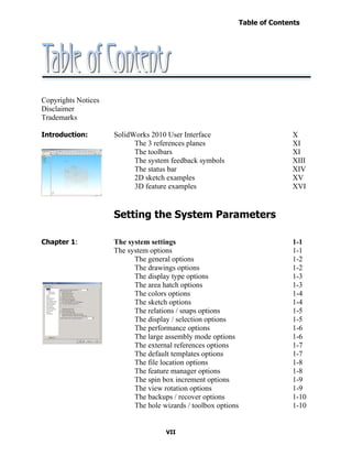
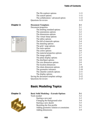
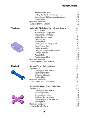
This document provides an introductory tutorial on SolidWorks that covers topics such as: - Setting system parameters and document templates - Basic solid modeling techniques like extruding and revolving parts - Pattern features, configurations, and modeling threads - Bottom-up assembly modeling and layout assemblies - Creating assembly and part drawings - Detailing techniques for drawings The tutorial is organized into multiple chapters that progressively build modeling and drawing skills in SolidWorks.


![74676371-Coagulation-and-Flocculation[1].ppt](https://cdn.slidesharecdn.com/ss_thumbnails/74676371-coagulation-and-flocculation1-260116154109-a3cbf55e-thumbnail.jpg?width=640&height=640&fit=bounds)


