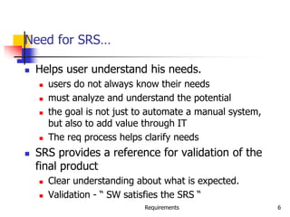
Requirements 1
Software Requirements
Analysis and Specification
UNIT-3
Requirements 2
Background
 Problem of scale is a key issue for SE
 For small scale, understand and specifying
requirements is easy
 For large problem - very hard; probably the
hardest, most problematic and error prone
 Input : user needs in minds of people
 Output : precise statement of what the future
system will do
Requirements 3
Background..
 Identifying and specifying req necessarily
involves people interaction
 Cannot be automated
 Requirement (IEEE)= A condition or capability
that must be possessed by a system
 Req. phase ends with a software requirements
specification (SRS) document
 SRS specifies what the proposed system
should do
Requirements 4
Background..
 Requirements understanding is hard
 Visualizing a future system is difficult
 Capability of the future system not clear, hence
needs not clear
 Requirements change with time
 …
 Essential to do a proper analysis and
specification of requirements
Requirements 5
Need for SRS
 SRS establishes basis of agreement
between the user and the supplier.
 Users needs have to be satisfied, but user
may not understand software
 Developers will develop the system, but
may not know about problem domain
 SRS is the medium to bridge the commn.
gap and specify user needs in a manner
both can understand
Requirements 6
Need for SRS…
 Helps user understand his needs.
 users do not always know their needs
 must analyze and understand the potential
 the goal is not just to automate a manual system,
but also to add value through IT
 The req process helps clarify needs
 SRS provides a reference for validation of the
final product
 Clear understanding about what is expected.
 Validation - “ SW satisfies the SRS “
Requirements 7
Need for SRS…
 High quality SRS essential for high Quality SW
 Requirement errors get manifested in final sw
 to satisfy the quality objective, must begin with
high quality SRS
 Requirements defects are not few
 25% of all defects in one case; 54% of all defects found
after UT
 80 defects in A7 that resulted in change requests
 500 / 250 defects in previously approved SRS.
Requirements 8
Need for SRS…
 Good SRS reduces the development cost
 SRS errors are expensive to fix later
 Req. changes can cost a lot (up to 40%)
 Good SRS can minimize changes and errors
 Substantial savings; extra effort spent
during req. saves multiple times that effort
 An Example
 Cost of fixing errors in req. , design ,
coding , acceptance testing and operation
are 2 , 5 , 15 , 50 , 150 person-months
Requirements 9
Need for SRS…
 Example …
 After req. phase 65% req errs detected in design ,
2% in coding, 30% in Acceptance testing, 3%
during operation
 If 50 requirement errors are not removed in the
req. phase, the total cost
32.5 *5 + 1*15 + 15*50 + 1.5*150 = 1152 hrs
 If 100 person-hours invested additionally in req to
catch these 50 defects , then development cost
could be reduced by 1152 person-hours.
 Net reduction in cost is 1052 person-hours
Requirements 10
Requirements Process
 Sequence of steps that need to be performed
to convert user needs into SRS
 Process has to elicit needs and requirements
and clearly specifies it
 Basic activities
 problem or requirement analysis
 requirement specification
 validation
 Analysis involves elicitation and is the hardest
Requirements 11
Requirements Process..
needs
Analysis
Specification
Validation
Requirements 12
Requirement process..
 Process is not linear, it is iterative and
parallel
 Overlap between phases - some parts
may be analyzed and specified
 Specification itself may help analysis
 Validation can show gaps that can lead
to further analysis and spec
Requirements 13
Requirements Process…
 Focus of analysis is on understanding the
desired systems and it’s requirements
 Divide and conquer is the basic strategy
 decompose into small parts, understand each part
and relation between parts
 Large volumes of information is generated
 organizing them is a key
 Techniques like data flow diagrams, object
diagrams etc. used in the analysis
Requirements 14
Requirements Process..
 Transition from analysis to specs is hard
 in specs, external behavior specified
 during analysis, structure and domain are
understood
 analysis structures helps in specification,
but the transition is not final
 methods of analysis are similar to that of
design, but objective and scope different
 analysis deals with the problem domain,
whereas design deals with solution domain
Requirements 15
Problem Analysis
 Aim: to gain an understanding of the needs,
requirements, and constraints on the software
 Analysis involves
 interviewing client and users
 reading manuals
 studying current systems
 helping client/users understand new possibilities
 Like becoming a consultant
 Must understand the working of the
organization , client and users
Requirements 16
Problem Analysis…
 Some issues
 Obtaining the necessary information
 Brainstorming: interacting with clients to
establish desired properties
 Information organization, as large amount
of info. gets collected
 Ensuring completeness
 Ensuring consistency
 Avoiding internal design
Requirements 17
Problem Analysis…
 Interpersonal issues are important
 Communication skills are very important
 Basic principle: problem partition
 Partition w.r.t what?
 Object - OO analysis
 Function - structural analysis
 Events in the system – event partitioning
 Projection - get different views
 Will discuss few different analysis techniques
Requirements 18
Characteristics of an SRS
 What should be the characteristics of a good
SRS? Some key ones are
 Complete
 Unambiguous
 Consistent
 Verifiable
 Ranked for importance and/or stability
Requirements 19
Characteristics…
 Correctness
 Each requirement accurately represents some
desired feature in the final system
 Completeness
 All desired features/characteristics specified
 Hardest to satisfy
 Completeness and correctness strongly related
 Unambiguous
 Each req has exactly one meaning
 Without this errors will creep in
 Important as natural languages often used
Requirements 20
Characteristics…
 Verifiability
 There must exist a cost effective way of checking
if sw satisfies requirements
 Consistent
 two requirements don’t contradict each other
 Ranked for importance/stability
 Needed for prioritizing in construction
 To reduce risks due to changing requirements
Requirements 21
Components of an SRS
 What should an SRS contain ?
 Clarifying this will help ensure
completeness
 An SRS must specify requirements on
 Functionality
 Performance
 Design constraints
 External interfaces
Requirements 22
Functional Requirements
 Heart of the SRS document; this forms the
bulk of the specs
 Specifies all the functionality that the system
should support
 Outputs for the given inputs and the
relationship between them
 All operations the system is to do
 Must specify behavior for invalid inputs too
Requirements 23
Performance Requirements
 All the performance constraints on the
software system
 Generally on response time ,
throughput etc => dynamic
 Capacity requirements => static
 Must be in measurable terms
(verifiability)
 Eg resp time should be xx 90% of the time
Requirements 24
Design Constraints
 Factors in the client environment that
restrict the choices
 Some such restrictions
 Standard compliance and compatibility with
other systems
 Hardware Limitations
 Reliability, fault tolerance, backup req.
 Security
Requirements 25
External Interface
 All interactions of the software with
people, hardware, and sw
 User interface most important
 General requirements of “friendliness”
should be avoided
 These should also be verifiable
Requirements 26
Specification Language
 Language should support desired char
of the SRS
 Formal languages are precise and
unambiguous but hard
 Natural languages mostly used, with
some structure for the document
 Formal languages used for special
features or in highly critical systems
Requirements 27
Structure of an SRS
 Introduction
 Purpose , the basic objective of the system
 Scope of what the system is to do , not to do
 Overview
 Overall description
 Product perspective
 Product functions
 User characteristics
 Assumptions
 Constraints
Requirements 28
Structure of an SRS…
 Specific requirements
 External interfaces
 Functional requirements
 Performance requirements
 Design constraints
 Acceptable criteria
 desirable to specify this up front.
 This standardization of the SRS was done by
IEEE.
Requirements 29
Use Cases Approach for
Functional Requirements
 Traditional approach for fn specs – specify
each function
 Use cases is a newer technique for specifying
behavior (functionality)
 I.e. focuses on functional specs only
 Though primarily for specification, can be
used in analysis and elicitation
 Can be used to specify business or org
behavior also, though we will focus on sw
 Well suited for interactive systems
Requirements 30
Use Cases Basics
 A use case captures a contract between
a user and system about behavior
 Basically a textual form; diagrams are
mostly to support
 Also useful in requirements elicitation as
users like and understand the story
telling form and react to it easily
Requirements 31
Basics..
 Actor: a person or a system that interacts with the
proposed system to achieve a goal
 Eg. User of an ATM (goal: get money); data entry operator;
(goal: Perform transaction)
 Actor is a logical entity, so receiver and sender actors
are different (even if the same person)
 Actors can be people or systems
 Primary actor: The main actor who initiates a UC
 UC is to satisfy his goals
 The actual execution may be done by a system or another
person on behalf of the Primary actor
Requirements 32
Basics..
 Scenario: a set of actions performed to
achieve a goal under some conditions
 Actions specified as a sequence of steps
 A step is a logically complete action performed
either by the actor or the system
 Main success scenario – when things go
normally and the goal is achieved
 Alternate scenarios: When things go wrong
and goals cannot be achieved
Requirements 33
Basics..
 A UC is a collection of many such
scenarios
 A scenario may employ other use cases
in a step
 I.e. a sub-goal of a UC goal may be
performed by another UC
 I.e. UCs can be organized hierarchically
Requirements 34
Basics…
 UCs specify functionality by describing
interactions between actors and system
 Focuses on external behavior
 UCs are primarily textual
 UC diagrams show UCs, actors, and dependencies
 They provide an overview
 Story like description easy to understand by
both users and analysts
 They do not form the complete SRS, only the
functionality part
Requirements 35
Example
Use Case 1: Buy stocks
Primary Actor: Purchaser
Goals of Stakeholders:
Purchaser: wants to buy stocks
Company: wants full transaction info
Precondition: User already has an account
Requirements 36
Example …
 Main Success Scenario
1. User selects to buy stocks
2. System gets name of web site from user for
trading
3. Establishes connection
4. User browses and buys stocks
5. System intercepts responses from the site and
updates user portfolio
6. System shows user new portfolio stading
Requirements 37
Example…
 Alternatives
 2a: System gives err msg, asks for new
suggestion for site, gives option to cancel
 3a: Web failure. 1-Sys reports failure to
user, backs up to previous step. 2-User
exits or tries again
 4a: Computer crashes
 4b: web site does not ack purchase
 5a: web site does not return needed info
Requirements 38
Example 2
 Use Case 2: Buy a product
 Primary actor: buyer/customer
 Goal: purchase some product
 Precondition: Customer is already
logged in
Requirements 39
Example 2…
 Main Scenario
1. Customer browses and selects items
2. Customer goes to checkout
3. Customer fills shipping options
4. System presents full pricing info
5. Customer fills credit card info
6. System authorizes purchase
7. System confirms sale
8. System sends confirming email
Requirements 40
Example 2…
 Alternatives
 6a: Credit card authorization fails
 Allows customer to reenter info
 3a: Regular customer
 System displays last 4 digits of credit card no
 Asks customer to OK it or change it
 Moves to step 6
Requirements 41
Example – An auction site
 Use Case1: Put an item for auction
 Primary Actor: Seller
 Precondition: Seller has logged in
 Main Success Scenario:
 Seller posts an item (its category, description, picture,
etc.) for auction
 System shows past prices of similar items to seller
 System specifies the starting bid price and a date when
auction will close
 System accepts the item and posts it
 Exception Scenarios:
 -- 2 a) There are no past items of this category
* System tells the seller this situation
Requirements 42
Example – auction site..
 Use Case2: Make a bid
 Primary Actor: Buyer
 Precondition: The buyer has logged in
 Main Success Scenario:
 Buyer searches or browses and selects some item
 System shows the rating of the seller, the starting bid, the
current bids, and the highest bid; asks buyer to make a bid
 Buyer specifies bid price, max bid price, and increment
 Systems accepts the bid; Blocks funds in bidders account
 System updates the bid price of other bidders where needed,
and updates the records for the item
Requirements 43
 Exception Scenarios:
 -- 3 a) The bid price is lower than the current
highest
* System informs the bidder and asks to rebid
 -- 4 a) The bidder does not have enough funds in
his account
* System cancels the bid, asks the user to get
more funds
Requirements 44
Example –auction site..
 Use Case3: Complete auction of an item
 Primary Actor: Auction System
 Precondition: The last date for bidding has been
reached
 Main Success Scenario:
 Select highest bidder; send email to selected bidder and seller
informing final bid price; send email to other bidders also
 Debit bidder’s account and credit seller’s account
 Transfer from seller’s account commission amount to
organization’s account
 Unblock other bidders funds
 Remove item from the site; update records
 Exception Scenarios: None
Requirements 45
Example – summary-level Use Case
 Use Case 0 : Auction an item
 Primary Actor: Auction system
 Scope: Auction conducting organization
 Precondition: None
 Main Success Scenario:
 Seller performs put an item for auction
 Various bidders make a bid
 On final date perform Complete the auction of
the item
 Get feed back from seller; get feedback from
buyer; update records
Requirements 46
Requirements with Use Cases
 UCs specify functional requirements
 Other req identified separately
 A complete SRS will contain the use
cases plus the other requirements
 Note – for system requirements it is
important to identify UCs for which the
system itself may be the actor
Requirements 47
Developing Use Cases
 UCs form a good medium for
brainstorming and discussions
 Hence can be used in elicitation and
problem analysis also
 UCs can be developed in a stepwise
refinement manner
 Many levels possible, but four naturally
emerge
Requirements 48
Developing…
 Step 1: Identify actors and goals
 Prepare an actor-goal list
 Provide a brief overview of the UC
 This defines the scope of the system
 Completeness can also be evaluated
 Step 2: Specify main Success Scenarios
 For each UC, expand main scenario
 This will provide the normal behavior of the
system
 Can be reviewed to ensure that interests of all
stakeholders and actors is met
Requirements 49
Developing…
 Step 3: Identify failure conditions
 List possible failure conditions for UCs
 For each step, identify how it may fail
 This step uncovers special situations
 Step 4: Specify failure handling
 Perhaps the hardest part
 Specify system behavior for the failure conditions
 New business rules and actors may emerge
Requirements 50
Other Approaches to Analysis
Requirements 51
Data Flow Modeling
 Widely used; focuses on functions
performed in the system
 Views a system as a network of data
transforms through which the data flows
 Uses data flow diagrams (DFDs) and
functional decomposition in modeling
 The SSAD methodology uses DFD to
organize information, and guide analysis
Requirements 52
Data flow diagrams
 A DFD shows flow of data through the
system
 Views system as transforming inputs to
outputs
 Transformation done through transforms
 DFD captures how transformation occurs
from input to output as data moves
through the transforms
 Not limited to software
Requirements 53
Data flow diagrams…
 DFD
 Transforms represented by named
circles/bubbles
 Bubbles connected by arrows on which
named data travels
 A rectangle represents a source or sink and
is originator/consumer of data (often
outside the system)
Requirements 54
DFD Example
Requirements 55
DFD Conventions
 External files shown as labeled straight lines
 Need for multiple data flows by a process
represented by * (means and)
 OR relationship represented by +
 All processes and arrows should be named
 Processes should represent transforms,
arrows should represent some data
Requirements 56
Data flow diagrams…
 Focus on what transforms happen , how
they are done is not important
 Usually major inputs/outputs shown,
minor are ignored in this modeling
 No loops , conditional thinking , …
 DFD is NOT a control chart, no
algorithmic design/thinking
 Sink/Source , external files
Requirements 57
Drawing a DFD
 If get stuck , reverse direction
 If control logic comes in , stop and restart
 Label each arrows and bubbles
 Make use of + & *
 Try drawing alternate DFDs
Leveled DFDs :
 DFD of a system may be very large
 Can organize it hierarchically
 Start with a top level DFD with a few bubbles
 then draw DFD for each bubble
 Preserve I/O when “ exploding”
Requirements 58
Drawing a DFD for a system
 Identify inputs, outputs, sources, sinks for the
system
 Work your way consistently from inputs to
outputs, and identify a few high-level
transforms to capture full transformation
 If get stuck, reverse direction
 When high-level transforms defined, then
refine each transform with more detailed
transformations
Requirements 59
Drawing a DFD for a system..
 Never show control logic; if thinking in
terms of loops/decisions, stop & restart
 Label each arrows and bubbles;
carefully identify inputs and outputs of
each transform
 Make use of + & *
 Try drawing alternate DFDs
Requirements 60
Leveled DFDs
 DFD of a system may be very large
 Can organize it hierarchically
 Start with a top level DFD with a few bubbles
 then draw DFD for each bubble
 Preserve I/O when “ exploding” a bubble so
consistency preserved
 Makes drawing the leveled DFD a top-down
refinement process, and allows modeling of
large and complex systems
Requirements 61
Data Dictionary
 In a DFD arrows are labeled with data items
 Data dictionary defines data flows in a DFD
 Shows structure of data; structure becomes
more visible when exploding
 Can use regular expressions to express the
structure of data
Requirements 62
Data Dictionary Example
 For the timesheet DFD
Weekly_timesheet – employee_name + id +
[regular_hrs + overtime_hrs]*
Pay_rate = [hourly | daily | weekly] +
dollar_amt
Employee_name = last + first + middle
Id = digit + digit + digit + digit
Requirements 63
DFD drawing – common errors
 Unlabeled data flows
 Missing data flows
 Extraneous data flows
 Consistency not maintained during
refinement
 Missing processes
 Too detailed or too abstract
 Contains some control information
Requirements 64
Prototyping
 Prototyping is another approach for
problem analysis
 Discussed it earlier with process – leads
to prototyping process model
Requirements 65
Requirements Validation
 Lot of room for misunderstanding
 Errors possible
 Expensive to fix req defects later
 Must try to remove most errors in SRS
 Most common errors
 Omission - 30%
 Inconsistency - 10-30%
 Incorrect fact - 10-30%
 Ambiguity - 5 -20%
Requirements 66
Requirements Review
 SRS reviewed by a group of people
 Group: author, client, user, dev team rep.
 Must include client and a user
 Process – standard inspection process
 Effectiveness - can catch 40-80% of req.
errors
Requirements 67
Summary
 Having a good quality SRS is essential for Q&P
 The req. phase has 3 major sub phases
 analysis , specification and validation
 Analysis
 for problem understanding and modeling
 Methods used: SSAD, OOA , Prototyping
 Key properties of an SRS: correctness,
completeness, consistency,unambiguousness
Requirements 68
Summary..
 Specification
 must contain functionality , performance ,
interfaces and design constraints
 Mostly natural languages used
 Use Cases is a method to specify the
functionality; also useful for analysis
 Validation - through reviews
Software Architecture 69
Software Architecture
Software Architecture 70
Background
 Any complex system is composed of
sub-systems that interact
 While designing systems, an approach
is to identify sub-systems and how they
interact with each other
 Sw Arch tries to do this for software
 A recent area, but a lot of interest in it
Software Architecture 71
Background…
 Architecture is the system design at the
highest level
 Choices about technologies, products to use,
servers, etc are made at arch level
 Not possible to design system details and then
accommodate these choices
 Arch must be created accommodating them
 Is the earliest place when properties like
rel/perf can be evaluated
Software Architecture 72
Architecture
 Arch is a design of the sw that gives a very
high level view of parts and they relate to
form the whole
 Partitions the sys in parts such that each part can
be comprehended independently
 And describes relationship between parts
 A complex system can be partitioned in many
diff ways, each providing a useful view
 Same holds true of software also
 There is no unique structure; many possible
Software Architecture 73
Architecture
 Defn: Software arch is the structure or
structures which comprise elements, their
externally visible properties, and relationships
among them
 For elements only interested in external properties
needed for relationship specification
 Details on how the properties are supported is not
important for arch
 The defn does not say anything about whether an
arch is good or not – analysis needed for it
 An arch description describes the different
structures of the system
Software Architecture 74
Key Uses of Arch Descriptions
 Understanding and communication
 By showing a system at a high level and
hiding complexity of parts, arch descr
facilitates communication
 To get a common understanding between
the diff stakeholders (users, clients,
architect, designer,…)
 For negotiation and agreement
 Arch descr can also aid in understanding of
existing systems
Software Architecture 75
Uses…
 Reuse
 A method of reuse is to compose systems from
parts and reuse existing parts
 This model is facilitated by reusing components at
a high level providing complete services
 To reuse existing components, arch must be
chosen such that these components fit together
with other components
 Hence, decision about using existing components
is made at arch design time
Software Architecture 76
Uses..
 Construction and evolution
 Some structures in arch descr will be used to
guide system development
 Partitioning at arch level can also be used for work
allocation to teams as parts are relatively
independent
 During sw evolution, arch helps decide what
needs to be changed to incorporate the new
changes/features
 Arch can help decide what is the impact of
changes to existing components on others
Software Architecture 77
Uses…
 Analysis
 If properties like perf, reliability can be determined
from design, alternatives can be considered during
design to reach the desired perf levels
 Sw arch opens such possibilities for software
(other engg disciplines usually can do this)
 E.g. rel and perf of a system can be predicted
from its arch, if estimates for parms like load etc is
provided
 Will require precise description of arch, as well as
properties of the elements in the description
Software Architecture 78
Architectural Views
 There is no unique arch of a sys
 There are different views of a sw sys
 A view consists of elements and relationships
between them, and describes a structure
 The elements of a view depends on what the
view wants to highlight
 Diff views expose diff properties
 A view focusing on some aspects reduces its
complexity
Software Architecture 79
Views…
 Many types of views have been proposed
 Most belong to one of these three types
 Module
 Component and Connector
 Allocation
 The diff views are not unrelated – they all
represent the same system
 There are relationships between elements of diff
views; this rel may be complex
Software Architecture 80
Views…
 Module view
 A sys is a collection of code units i.e. they
do not represent runtime entitites
 I.e. elements are modules, eg. Class,
package, function, procedure,…
 Relationship between them is code based,
e.g. part of, depends on, calls,
generalization-specialization,..
Software Architecture 81
Views…
 Component and Connector (C&C)
 Elements are run time entities called
components
 I.e. a component is a unit that has identity
in executing sys, e.g. objects, processes,
.exe, .dll
 Connectors provide means of interaction
between components, e.g. pipes, shared
memory, sockets
Software Architecture 82
Views…
 Allocation view
 Focuses on how sw units are allocated to
resources like hw, file system, people
 I.e. specifies relationship between sw
elements and execution units in the env
 Expose structural properties like which
process runs on which processor, which file
resides where, …
Software Architecture 83
Views…
 An arch description consists of views of diff
types, each showing a diff structure
 Diff sys need diff types of views depending on the
needs
 E.g. for perf analysis, allocation view is necessary;
for planning, module view helps
 The C&C view is almost always done, and has
become the primary view
 We focus primarily on the C&C view
 Module view is covered in high level design,
whose focus is on identifying modules
Software Architecture 84
Component and Connector View
 Two main elements – components and connectors
 Components: Computational elements or data stores
 Connectors: Means of interaction between comps
 A C&C view defines the comps, and which comps are
connected through which connector
 The C&C view describes a runtime structure of the
system – what comps exist at runtime and how they
interact during execution
 Is a graph; often shown as a box-and-line drawing
 Most commonly used structure
Software Architecture 85
Components
 Units of computations or data stores
 Has a name, which represents its role, and
provides it identity
 A comp may have a type; diff types rep by
diff symbols in C&C view
 Comps use ports (or interfaces) to
communicate with others
 An arch can use any symbols to rep
components; some common ones are shown
Software Architecture 86
Some Component examples…
Software Architecture 87
Connectors
 Interaction between components happen
through connectors
 A connector may be provided by the runtime
environment, e.g. procedure call
 But there may be complex mechanisms for
interaction, e.g http, tcp/ip, ports,…; a lot of
sw needed to support them
 Important to identify them explicitly; also
needed for programming comps properly
Software Architecture 88
Connectors…
 Connectors need not be binary, e.g. a
broadcast bus
 Connector has a name (and a type)
 Often connectors represented as protocol –
i.e. comps need to follow some conventions
when using the connector
 Best to use diff notation for diff types of
connectors; all connectors should not be
shown by simple lines
Software Architecture 89
Connector examples
Software Architecture 90
An Example
 Design a system for taking online survey of
students on campus
 Multiple choice questions, students submit online
 When a student submits, current result of the
survey is shown
 Is best built using web; a 3-tier architecture
is proposed
 Has a client, server, and a database components
(each of a diff type)
 Connector between them are also of diff types
Software Architecture 91
Example…
Software Architecture 92
Example…
 At arch level, details are not needed
 The connectors are explicitly stated,
which implies that the infrastructure
should provide http, browser, etc.
 The choice of connectors imposes
constraints on how the components are
finally designed and built
Software Architecture 93
Extension 1
 This arch has no security – anyone can
take the survey
 We want that only registered students
can take the survey (at most once)
 To identify students and check for one-only
submission, need a authentication server
 Need to use cookies, and server has to be
built accordingly (the connector between
server and auth server is http with cookies)
Software Architecture 94
Extension 1…
Software Architecture 95
Extension 2
 It was found that DB is frequently down
 For improving reliability, want that if DB
is down, student is given an older
survey result and survey data stored
 The survey data given can be outdated
by at most 5 survey data points
 For this, will add a cache comp, which
will store data as well as results
Software Architecture 96
Extension 2…
Software Architecture 97
Example…
 One change increased security, 2nd
increased performance and reliability
 I.e. Arch level choices have a big
impact on system properties
 That is why, choosing a suitable arch
can help build a good system
Software Architecture 98
Architectural Styles for C&C View
 Diff systems have diff C&C structure
 Some structures are general and are useful
for a class of problems – architectural styles
 An arch style defines a family of archs that
satisfy the constraint of that style
 Styles can provide ideas for creating arch for
a sys; they can be combined also
 We discuss a few common styles
Software Architecture 99
Pipe and filter
 Well suited for systems that mainly do data
transformations
 A system using this style uses a network of
transforms to achieve the desired result
 Has one component type – filter
 Has one connector type – pipe
 A filter does some transformation and passes
data to other filters through pipes
Software Architecture 100
Pipe and Filter…
 A filter is independent; need not know the id
of filters sending/receiving data
 Filters can be asynchronous and are
producers or consumers of data
 A pipe is unidirectional channel which moves
streams of data from one filter to another
 A pipe is a 2-way connector
 Pipes have to perform buffering, and
synchronization between filters
Software Architecture 101
Pipe and filter…
 Pipes should work without knowing the
identify of producers/consumers
 A pipe must connect the output port of
one filter to input port of another
 Filters may have indep thread of control
Software Architecture 102
Example
 A system needed to count the
frequency of different words in a file
 One approach: first split the file into a
sequence of words, sort them, then
count the #of occurrences
 The arch of this system can naturally
use the pipe and filter style
Software Architecture 103
Example..
Software Architecture 104
Shared-data style
 Two component types – data repository and
data accessor
 Data repository – provides reliable permanent
storage
 Data accessors – access data in repositories,
perform computations, and may put the
results back also
 Communication between data accessors is
only through the repository
Software Architecture 105
Shared-data style…
 Two variations possible
 Black board style: if data is posted in a
repository, all accessors are informed; i.e.
shared data source is an active agent
 Repository style: passive repository
 Eg. database oriented systems; web
systems; programming environments,..
Software Architecture 106
Example
 A student registration system of a
university
 Repository contains all the data about
students, courses, schedules,…
 Accessors like admin, approvals,
registration, reports which perform
operations on the data
Software Architecture 107
Example…
Software Architecture 108
Example..
 Components do not directly
communicate with each other
 Easy to extend – if a scheduler is
needed, it is added as a new accessor
 No existing component needs to be
changed
 Only one connector style in this –
read/write
Software Architecture 109
Client-Server Style
 Two component types – clients and servers
 Clients can only communicate with the server,
but not with other clients
 Communication is initiated by a client which
sends request and server responds
 One connector type – request/reply, which is
asymmetric
 Often the client and the servers reside on
different machines
Software Architecture 110
Client-server style…
 A general form of this style is the n-tier
structure
 A 3-tier structure is commonly used by
many application and web systems
 Client-tier contains the clients
 Middle-tier contains the business rules
 Database tier has the information
Software Architecture 111
Some other styles
 Publish-subscribe style
 Some components generate events, and others
subscribe to them
 On an event, those component that subscribe to it
are invoked
 Peer-to-peer style
 Like object oriented systems; components use
services from each other through methods
 Communication processes style
 Processes which execute and communicate with
each other through message passing
Software Architecture 112
Architecture and Design
 Both arch and design partition the system
into parts and their org
 What is the relationship between design and
arch?
 Arch is a design; it is about the solution domain,
and not problem domain
 Can view arch as a very high level design focusing
on main components
 Design is about modules in these components that
have to be coded
 Design can be considered as providing the module
view of the system
Software Architecture 113
Contd…
 Boundaries between architecture and design
are not clear or hard
 It is for designer and architect to decide
where arch ends and design begins
 In arch, issues like files, data structure etc
are not considered, while they are important
in design
 Arch does impose constraints on design in
that the design must be consistent with arch
Software Architecture 114
Preserving the Integrity of
Architecture
 What is the role of arch during the rest of the
development process
 Many designers and developers use it for
understanding but nothing more
 Arch imposes constraints; the implementation must
preserve the arch
 I.e. the arch of the final system should be same as
the arch that was conceived
 It is very easy to ignore the arch design and go
ahead and do the development
 Example – impl of the word frequency problem
Software Architecture 115
Documenting Arch Design
 While designing and brainstorming,
diagrams are a good means
 Diagrams are not sufficient for
documenting arch design
 An arch design document will need to
precisely specify the views, and the
relationship between them
Software Architecture 116
Documenting…
 An arch document should contain
 System and architecture context
 Description of architecture views
 Across view documentation
 A context diagram that establishes the sys
scope, key actors, and data sources/sinks can
provide the overall context
 A view description will generally have a
pictorial representation, as discussed earlier
Software Architecture 117
Documenting…
 Pictures should be supported by
 Element catalog: Info about behavior,
interfaces of the elements in the arch
 Architectural rationale: Reasons for making
the choices that were made
 Behavior: Of the system in different
scenarios (e.g. collaboration diagram)
 Other Information: Decisions which are to
be taken, choices still to be made,..
Software Architecture 118
Documenting…
 Inter-view documentation
 Views are related, but the relationship is not clear
in the view
 This part of the doc describes how the views are
related (eg. How modules are related to
components)
 Rationale for choosing the views
 Any info that cuts across views
 Sometimes views may be combined in one
diagram for this – should be done if the
resulting diagram is still easy to understand
Software Architecture 119
Evaluating Architectures
 Arch impacts non-functional attributes like
modifiability, performance, reliability,
portability, etc
 Attr. like usability etc are not impacted
 Arch plays a much bigger impact on these
than later decisions
 So should evaluate a proposed arch for these
properties
 Q: How should this evaluation be done?
 Many different ways
Software Architecture 120
Evaluating Architectures…
 Procedural approach – follow a sequence of
steps
 Identify the attributes of interest to different
stakeholders
 List them in a table
 For each attribute, evaluate the architectures
under consideration
 Evaluation can be subjective based on experience
 Based on this table, then select some arch or
improve some existing arch for some attribute
Software Architecture 121
Summary
 Arch of a sw system is its structures
comprising of elements, their external
properties, and relationships
 Arch is a high level design
 Three main view types – module, component
and connector, and allocation
 Component and connector (C&C) view is
most commonly used
Software Architecture 122
Summary…
 There are some C&C styles that are
commonly used, e.g. pipe-and-filter,
shared data, client server,....
 An arch description should document
the different views and their
relationship – views can be combined
 Rationale and other supporting
information should also be captured
Software Architecture 123
Summary…
 Arch can be analyzed for various non-
functional attributes like performance,
reliability, security, etc
 ATAM is one approach for analyzing
architectures, which evaluates
attributes of interest under different
scenarios

software requirement and architecture.pdf

  • 1.
  • 2.
    Requirements 2 Background  Problemof scale is a key issue for SE  For small scale, understand and specifying requirements is easy  For large problem - very hard; probably the hardest, most problematic and error prone  Input : user needs in minds of people  Output : precise statement of what the future system will do
  • 3.
    Requirements 3 Background..  Identifyingand specifying req necessarily involves people interaction  Cannot be automated  Requirement (IEEE)= A condition or capability that must be possessed by a system  Req. phase ends with a software requirements specification (SRS) document  SRS specifies what the proposed system should do
  • 4.
    Requirements 4 Background..  Requirementsunderstanding is hard  Visualizing a future system is difficult  Capability of the future system not clear, hence needs not clear  Requirements change with time  …  Essential to do a proper analysis and specification of requirements
  • 5.
    Requirements 5 Need forSRS  SRS establishes basis of agreement between the user and the supplier.  Users needs have to be satisfied, but user may not understand software  Developers will develop the system, but may not know about problem domain  SRS is the medium to bridge the commn. gap and specify user needs in a manner both can understand
  • 6.
    Requirements 6 Need forSRS…  Helps user understand his needs.  users do not always know their needs  must analyze and understand the potential  the goal is not just to automate a manual system, but also to add value through IT  The req process helps clarify needs  SRS provides a reference for validation of the final product  Clear understanding about what is expected.  Validation - “ SW satisfies the SRS “
  • 7.
    Requirements 7 Need forSRS…  High quality SRS essential for high Quality SW  Requirement errors get manifested in final sw  to satisfy the quality objective, must begin with high quality SRS  Requirements defects are not few  25% of all defects in one case; 54% of all defects found after UT  80 defects in A7 that resulted in change requests  500 / 250 defects in previously approved SRS.
  • 8.
    Requirements 8 Need forSRS…  Good SRS reduces the development cost  SRS errors are expensive to fix later  Req. changes can cost a lot (up to 40%)  Good SRS can minimize changes and errors  Substantial savings; extra effort spent during req. saves multiple times that effort  An Example  Cost of fixing errors in req. , design , coding , acceptance testing and operation are 2 , 5 , 15 , 50 , 150 person-months
  • 9.
    Requirements 9 Need forSRS…  Example …  After req. phase 65% req errs detected in design , 2% in coding, 30% in Acceptance testing, 3% during operation  If 50 requirement errors are not removed in the req. phase, the total cost 32.5 *5 + 1*15 + 15*50 + 1.5*150 = 1152 hrs  If 100 person-hours invested additionally in req to catch these 50 defects , then development cost could be reduced by 1152 person-hours.  Net reduction in cost is 1052 person-hours
  • 10.
    Requirements 10 Requirements Process Sequence of steps that need to be performed to convert user needs into SRS  Process has to elicit needs and requirements and clearly specifies it  Basic activities  problem or requirement analysis  requirement specification  validation  Analysis involves elicitation and is the hardest
  • 11.
  • 12.
    Requirements 12 Requirement process.. Process is not linear, it is iterative and parallel  Overlap between phases - some parts may be analyzed and specified  Specification itself may help analysis  Validation can show gaps that can lead to further analysis and spec
  • 13.
    Requirements 13 Requirements Process… Focus of analysis is on understanding the desired systems and it’s requirements  Divide and conquer is the basic strategy  decompose into small parts, understand each part and relation between parts  Large volumes of information is generated  organizing them is a key  Techniques like data flow diagrams, object diagrams etc. used in the analysis
  • 14.
    Requirements 14 Requirements Process.. Transition from analysis to specs is hard  in specs, external behavior specified  during analysis, structure and domain are understood  analysis structures helps in specification, but the transition is not final  methods of analysis are similar to that of design, but objective and scope different  analysis deals with the problem domain, whereas design deals with solution domain
  • 15.
    Requirements 15 Problem Analysis Aim: to gain an understanding of the needs, requirements, and constraints on the software  Analysis involves  interviewing client and users  reading manuals  studying current systems  helping client/users understand new possibilities  Like becoming a consultant  Must understand the working of the organization , client and users
  • 16.
    Requirements 16 Problem Analysis… Some issues  Obtaining the necessary information  Brainstorming: interacting with clients to establish desired properties  Information organization, as large amount of info. gets collected  Ensuring completeness  Ensuring consistency  Avoiding internal design
  • 17.
    Requirements 17 Problem Analysis… Interpersonal issues are important  Communication skills are very important  Basic principle: problem partition  Partition w.r.t what?  Object - OO analysis  Function - structural analysis  Events in the system – event partitioning  Projection - get different views  Will discuss few different analysis techniques
  • 18.
    Requirements 18 Characteristics ofan SRS  What should be the characteristics of a good SRS? Some key ones are  Complete  Unambiguous  Consistent  Verifiable  Ranked for importance and/or stability
  • 19.
    Requirements 19 Characteristics…  Correctness Each requirement accurately represents some desired feature in the final system  Completeness  All desired features/characteristics specified  Hardest to satisfy  Completeness and correctness strongly related  Unambiguous  Each req has exactly one meaning  Without this errors will creep in  Important as natural languages often used
  • 20.
    Requirements 20 Characteristics…  Verifiability There must exist a cost effective way of checking if sw satisfies requirements  Consistent  two requirements don’t contradict each other  Ranked for importance/stability  Needed for prioritizing in construction  To reduce risks due to changing requirements
  • 21.
    Requirements 21 Components ofan SRS  What should an SRS contain ?  Clarifying this will help ensure completeness  An SRS must specify requirements on  Functionality  Performance  Design constraints  External interfaces
  • 22.
    Requirements 22 Functional Requirements Heart of the SRS document; this forms the bulk of the specs  Specifies all the functionality that the system should support  Outputs for the given inputs and the relationship between them  All operations the system is to do  Must specify behavior for invalid inputs too
  • 23.
    Requirements 23 Performance Requirements All the performance constraints on the software system  Generally on response time , throughput etc => dynamic  Capacity requirements => static  Must be in measurable terms (verifiability)  Eg resp time should be xx 90% of the time
  • 24.
    Requirements 24 Design Constraints Factors in the client environment that restrict the choices  Some such restrictions  Standard compliance and compatibility with other systems  Hardware Limitations  Reliability, fault tolerance, backup req.  Security
  • 25.
    Requirements 25 External Interface All interactions of the software with people, hardware, and sw  User interface most important  General requirements of “friendliness” should be avoided  These should also be verifiable
  • 26.
    Requirements 26 Specification Language Language should support desired char of the SRS  Formal languages are precise and unambiguous but hard  Natural languages mostly used, with some structure for the document  Formal languages used for special features or in highly critical systems
  • 27.
    Requirements 27 Structure ofan SRS  Introduction  Purpose , the basic objective of the system  Scope of what the system is to do , not to do  Overview  Overall description  Product perspective  Product functions  User characteristics  Assumptions  Constraints
  • 28.
    Requirements 28 Structure ofan SRS…  Specific requirements  External interfaces  Functional requirements  Performance requirements  Design constraints  Acceptable criteria  desirable to specify this up front.  This standardization of the SRS was done by IEEE.
  • 29.
    Requirements 29 Use CasesApproach for Functional Requirements  Traditional approach for fn specs – specify each function  Use cases is a newer technique for specifying behavior (functionality)  I.e. focuses on functional specs only  Though primarily for specification, can be used in analysis and elicitation  Can be used to specify business or org behavior also, though we will focus on sw  Well suited for interactive systems
  • 30.
    Requirements 30 Use CasesBasics  A use case captures a contract between a user and system about behavior  Basically a textual form; diagrams are mostly to support  Also useful in requirements elicitation as users like and understand the story telling form and react to it easily
  • 31.
    Requirements 31 Basics..  Actor:a person or a system that interacts with the proposed system to achieve a goal  Eg. User of an ATM (goal: get money); data entry operator; (goal: Perform transaction)  Actor is a logical entity, so receiver and sender actors are different (even if the same person)  Actors can be people or systems  Primary actor: The main actor who initiates a UC  UC is to satisfy his goals  The actual execution may be done by a system or another person on behalf of the Primary actor
  • 32.
    Requirements 32 Basics..  Scenario:a set of actions performed to achieve a goal under some conditions  Actions specified as a sequence of steps  A step is a logically complete action performed either by the actor or the system  Main success scenario – when things go normally and the goal is achieved  Alternate scenarios: When things go wrong and goals cannot be achieved
  • 33.
    Requirements 33 Basics..  AUC is a collection of many such scenarios  A scenario may employ other use cases in a step  I.e. a sub-goal of a UC goal may be performed by another UC  I.e. UCs can be organized hierarchically
  • 34.
    Requirements 34 Basics…  UCsspecify functionality by describing interactions between actors and system  Focuses on external behavior  UCs are primarily textual  UC diagrams show UCs, actors, and dependencies  They provide an overview  Story like description easy to understand by both users and analysts  They do not form the complete SRS, only the functionality part
  • 35.
    Requirements 35 Example Use Case1: Buy stocks Primary Actor: Purchaser Goals of Stakeholders: Purchaser: wants to buy stocks Company: wants full transaction info Precondition: User already has an account
  • 36.
    Requirements 36 Example … Main Success Scenario 1. User selects to buy stocks 2. System gets name of web site from user for trading 3. Establishes connection 4. User browses and buys stocks 5. System intercepts responses from the site and updates user portfolio 6. System shows user new portfolio stading
  • 37.
    Requirements 37 Example…  Alternatives 2a: System gives err msg, asks for new suggestion for site, gives option to cancel  3a: Web failure. 1-Sys reports failure to user, backs up to previous step. 2-User exits or tries again  4a: Computer crashes  4b: web site does not ack purchase  5a: web site does not return needed info
  • 38.
    Requirements 38 Example 2 Use Case 2: Buy a product  Primary actor: buyer/customer  Goal: purchase some product  Precondition: Customer is already logged in
  • 39.
    Requirements 39 Example 2… Main Scenario 1. Customer browses and selects items 2. Customer goes to checkout 3. Customer fills shipping options 4. System presents full pricing info 5. Customer fills credit card info 6. System authorizes purchase 7. System confirms sale 8. System sends confirming email
  • 40.
    Requirements 40 Example 2… Alternatives  6a: Credit card authorization fails  Allows customer to reenter info  3a: Regular customer  System displays last 4 digits of credit card no  Asks customer to OK it or change it  Moves to step 6
  • 41.
    Requirements 41 Example –An auction site  Use Case1: Put an item for auction  Primary Actor: Seller  Precondition: Seller has logged in  Main Success Scenario:  Seller posts an item (its category, description, picture, etc.) for auction  System shows past prices of similar items to seller  System specifies the starting bid price and a date when auction will close  System accepts the item and posts it  Exception Scenarios:  -- 2 a) There are no past items of this category * System tells the seller this situation
  • 42.
    Requirements 42 Example –auction site..  Use Case2: Make a bid  Primary Actor: Buyer  Precondition: The buyer has logged in  Main Success Scenario:  Buyer searches or browses and selects some item  System shows the rating of the seller, the starting bid, the current bids, and the highest bid; asks buyer to make a bid  Buyer specifies bid price, max bid price, and increment  Systems accepts the bid; Blocks funds in bidders account  System updates the bid price of other bidders where needed, and updates the records for the item
  • 43.
    Requirements 43  ExceptionScenarios:  -- 3 a) The bid price is lower than the current highest * System informs the bidder and asks to rebid  -- 4 a) The bidder does not have enough funds in his account * System cancels the bid, asks the user to get more funds
  • 44.
    Requirements 44 Example –auctionsite..  Use Case3: Complete auction of an item  Primary Actor: Auction System  Precondition: The last date for bidding has been reached  Main Success Scenario:  Select highest bidder; send email to selected bidder and seller informing final bid price; send email to other bidders also  Debit bidder’s account and credit seller’s account  Transfer from seller’s account commission amount to organization’s account  Unblock other bidders funds  Remove item from the site; update records  Exception Scenarios: None
  • 45.
    Requirements 45 Example –summary-level Use Case  Use Case 0 : Auction an item  Primary Actor: Auction system  Scope: Auction conducting organization  Precondition: None  Main Success Scenario:  Seller performs put an item for auction  Various bidders make a bid  On final date perform Complete the auction of the item  Get feed back from seller; get feedback from buyer; update records
  • 46.
    Requirements 46 Requirements withUse Cases  UCs specify functional requirements  Other req identified separately  A complete SRS will contain the use cases plus the other requirements  Note – for system requirements it is important to identify UCs for which the system itself may be the actor
  • 47.
    Requirements 47 Developing UseCases  UCs form a good medium for brainstorming and discussions  Hence can be used in elicitation and problem analysis also  UCs can be developed in a stepwise refinement manner  Many levels possible, but four naturally emerge
  • 48.
    Requirements 48 Developing…  Step1: Identify actors and goals  Prepare an actor-goal list  Provide a brief overview of the UC  This defines the scope of the system  Completeness can also be evaluated  Step 2: Specify main Success Scenarios  For each UC, expand main scenario  This will provide the normal behavior of the system  Can be reviewed to ensure that interests of all stakeholders and actors is met
  • 49.
    Requirements 49 Developing…  Step3: Identify failure conditions  List possible failure conditions for UCs  For each step, identify how it may fail  This step uncovers special situations  Step 4: Specify failure handling  Perhaps the hardest part  Specify system behavior for the failure conditions  New business rules and actors may emerge
  • 50.
  • 51.
    Requirements 51 Data FlowModeling  Widely used; focuses on functions performed in the system  Views a system as a network of data transforms through which the data flows  Uses data flow diagrams (DFDs) and functional decomposition in modeling  The SSAD methodology uses DFD to organize information, and guide analysis
  • 52.
    Requirements 52 Data flowdiagrams  A DFD shows flow of data through the system  Views system as transforming inputs to outputs  Transformation done through transforms  DFD captures how transformation occurs from input to output as data moves through the transforms  Not limited to software
  • 53.
    Requirements 53 Data flowdiagrams…  DFD  Transforms represented by named circles/bubbles  Bubbles connected by arrows on which named data travels  A rectangle represents a source or sink and is originator/consumer of data (often outside the system)
  • 54.
  • 55.
    Requirements 55 DFD Conventions External files shown as labeled straight lines  Need for multiple data flows by a process represented by * (means and)  OR relationship represented by +  All processes and arrows should be named  Processes should represent transforms, arrows should represent some data
  • 56.
    Requirements 56 Data flowdiagrams…  Focus on what transforms happen , how they are done is not important  Usually major inputs/outputs shown, minor are ignored in this modeling  No loops , conditional thinking , …  DFD is NOT a control chart, no algorithmic design/thinking  Sink/Source , external files
  • 57.
    Requirements 57 Drawing aDFD  If get stuck , reverse direction  If control logic comes in , stop and restart  Label each arrows and bubbles  Make use of + & *  Try drawing alternate DFDs Leveled DFDs :  DFD of a system may be very large  Can organize it hierarchically  Start with a top level DFD with a few bubbles  then draw DFD for each bubble  Preserve I/O when “ exploding”
  • 58.
    Requirements 58 Drawing aDFD for a system  Identify inputs, outputs, sources, sinks for the system  Work your way consistently from inputs to outputs, and identify a few high-level transforms to capture full transformation  If get stuck, reverse direction  When high-level transforms defined, then refine each transform with more detailed transformations
  • 59.
    Requirements 59 Drawing aDFD for a system..  Never show control logic; if thinking in terms of loops/decisions, stop & restart  Label each arrows and bubbles; carefully identify inputs and outputs of each transform  Make use of + & *  Try drawing alternate DFDs
  • 60.
    Requirements 60 Leveled DFDs DFD of a system may be very large  Can organize it hierarchically  Start with a top level DFD with a few bubbles  then draw DFD for each bubble  Preserve I/O when “ exploding” a bubble so consistency preserved  Makes drawing the leveled DFD a top-down refinement process, and allows modeling of large and complex systems
  • 61.
    Requirements 61 Data Dictionary In a DFD arrows are labeled with data items  Data dictionary defines data flows in a DFD  Shows structure of data; structure becomes more visible when exploding  Can use regular expressions to express the structure of data
  • 62.
    Requirements 62 Data DictionaryExample  For the timesheet DFD Weekly_timesheet – employee_name + id + [regular_hrs + overtime_hrs]* Pay_rate = [hourly | daily | weekly] + dollar_amt Employee_name = last + first + middle Id = digit + digit + digit + digit
  • 63.
    Requirements 63 DFD drawing– common errors  Unlabeled data flows  Missing data flows  Extraneous data flows  Consistency not maintained during refinement  Missing processes  Too detailed or too abstract  Contains some control information
  • 64.
    Requirements 64 Prototyping  Prototypingis another approach for problem analysis  Discussed it earlier with process – leads to prototyping process model
  • 65.
    Requirements 65 Requirements Validation Lot of room for misunderstanding  Errors possible  Expensive to fix req defects later  Must try to remove most errors in SRS  Most common errors  Omission - 30%  Inconsistency - 10-30%  Incorrect fact - 10-30%  Ambiguity - 5 -20%
  • 66.
    Requirements 66 Requirements Review SRS reviewed by a group of people  Group: author, client, user, dev team rep.  Must include client and a user  Process – standard inspection process  Effectiveness - can catch 40-80% of req. errors
  • 67.
    Requirements 67 Summary  Havinga good quality SRS is essential for Q&P  The req. phase has 3 major sub phases  analysis , specification and validation  Analysis  for problem understanding and modeling  Methods used: SSAD, OOA , Prototyping  Key properties of an SRS: correctness, completeness, consistency,unambiguousness
  • 68.
    Requirements 68 Summary..  Specification must contain functionality , performance , interfaces and design constraints  Mostly natural languages used  Use Cases is a method to specify the functionality; also useful for analysis  Validation - through reviews
  • 69.
  • 70.
    Software Architecture 70 Background Any complex system is composed of sub-systems that interact  While designing systems, an approach is to identify sub-systems and how they interact with each other  Sw Arch tries to do this for software  A recent area, but a lot of interest in it
  • 71.
    Software Architecture 71 Background… Architecture is the system design at the highest level  Choices about technologies, products to use, servers, etc are made at arch level  Not possible to design system details and then accommodate these choices  Arch must be created accommodating them  Is the earliest place when properties like rel/perf can be evaluated
  • 72.
    Software Architecture 72 Architecture Arch is a design of the sw that gives a very high level view of parts and they relate to form the whole  Partitions the sys in parts such that each part can be comprehended independently  And describes relationship between parts  A complex system can be partitioned in many diff ways, each providing a useful view  Same holds true of software also  There is no unique structure; many possible
  • 73.
    Software Architecture 73 Architecture Defn: Software arch is the structure or structures which comprise elements, their externally visible properties, and relationships among them  For elements only interested in external properties needed for relationship specification  Details on how the properties are supported is not important for arch  The defn does not say anything about whether an arch is good or not – analysis needed for it  An arch description describes the different structures of the system
  • 74.
    Software Architecture 74 KeyUses of Arch Descriptions  Understanding and communication  By showing a system at a high level and hiding complexity of parts, arch descr facilitates communication  To get a common understanding between the diff stakeholders (users, clients, architect, designer,…)  For negotiation and agreement  Arch descr can also aid in understanding of existing systems
  • 75.
    Software Architecture 75 Uses… Reuse  A method of reuse is to compose systems from parts and reuse existing parts  This model is facilitated by reusing components at a high level providing complete services  To reuse existing components, arch must be chosen such that these components fit together with other components  Hence, decision about using existing components is made at arch design time
  • 76.
    Software Architecture 76 Uses.. Construction and evolution  Some structures in arch descr will be used to guide system development  Partitioning at arch level can also be used for work allocation to teams as parts are relatively independent  During sw evolution, arch helps decide what needs to be changed to incorporate the new changes/features  Arch can help decide what is the impact of changes to existing components on others
  • 77.
    Software Architecture 77 Uses… Analysis  If properties like perf, reliability can be determined from design, alternatives can be considered during design to reach the desired perf levels  Sw arch opens such possibilities for software (other engg disciplines usually can do this)  E.g. rel and perf of a system can be predicted from its arch, if estimates for parms like load etc is provided  Will require precise description of arch, as well as properties of the elements in the description
  • 78.
    Software Architecture 78 ArchitecturalViews  There is no unique arch of a sys  There are different views of a sw sys  A view consists of elements and relationships between them, and describes a structure  The elements of a view depends on what the view wants to highlight  Diff views expose diff properties  A view focusing on some aspects reduces its complexity
  • 79.
    Software Architecture 79 Views… Many types of views have been proposed  Most belong to one of these three types  Module  Component and Connector  Allocation  The diff views are not unrelated – they all represent the same system  There are relationships between elements of diff views; this rel may be complex
  • 80.
    Software Architecture 80 Views… Module view  A sys is a collection of code units i.e. they do not represent runtime entitites  I.e. elements are modules, eg. Class, package, function, procedure,…  Relationship between them is code based, e.g. part of, depends on, calls, generalization-specialization,..
  • 81.
    Software Architecture 81 Views… Component and Connector (C&C)  Elements are run time entities called components  I.e. a component is a unit that has identity in executing sys, e.g. objects, processes, .exe, .dll  Connectors provide means of interaction between components, e.g. pipes, shared memory, sockets
  • 82.
    Software Architecture 82 Views… Allocation view  Focuses on how sw units are allocated to resources like hw, file system, people  I.e. specifies relationship between sw elements and execution units in the env  Expose structural properties like which process runs on which processor, which file resides where, …
  • 83.
    Software Architecture 83 Views… An arch description consists of views of diff types, each showing a diff structure  Diff sys need diff types of views depending on the needs  E.g. for perf analysis, allocation view is necessary; for planning, module view helps  The C&C view is almost always done, and has become the primary view  We focus primarily on the C&C view  Module view is covered in high level design, whose focus is on identifying modules
  • 84.
    Software Architecture 84 Componentand Connector View  Two main elements – components and connectors  Components: Computational elements or data stores  Connectors: Means of interaction between comps  A C&C view defines the comps, and which comps are connected through which connector  The C&C view describes a runtime structure of the system – what comps exist at runtime and how they interact during execution  Is a graph; often shown as a box-and-line drawing  Most commonly used structure
  • 85.
    Software Architecture 85 Components Units of computations or data stores  Has a name, which represents its role, and provides it identity  A comp may have a type; diff types rep by diff symbols in C&C view  Comps use ports (or interfaces) to communicate with others  An arch can use any symbols to rep components; some common ones are shown
  • 86.
    Software Architecture 86 SomeComponent examples…
  • 87.
    Software Architecture 87 Connectors Interaction between components happen through connectors  A connector may be provided by the runtime environment, e.g. procedure call  But there may be complex mechanisms for interaction, e.g http, tcp/ip, ports,…; a lot of sw needed to support them  Important to identify them explicitly; also needed for programming comps properly
  • 88.
    Software Architecture 88 Connectors… Connectors need not be binary, e.g. a broadcast bus  Connector has a name (and a type)  Often connectors represented as protocol – i.e. comps need to follow some conventions when using the connector  Best to use diff notation for diff types of connectors; all connectors should not be shown by simple lines
  • 89.
  • 90.
    Software Architecture 90 AnExample  Design a system for taking online survey of students on campus  Multiple choice questions, students submit online  When a student submits, current result of the survey is shown  Is best built using web; a 3-tier architecture is proposed  Has a client, server, and a database components (each of a diff type)  Connector between them are also of diff types
  • 91.
  • 92.
    Software Architecture 92 Example… At arch level, details are not needed  The connectors are explicitly stated, which implies that the infrastructure should provide http, browser, etc.  The choice of connectors imposes constraints on how the components are finally designed and built
  • 93.
    Software Architecture 93 Extension1  This arch has no security – anyone can take the survey  We want that only registered students can take the survey (at most once)  To identify students and check for one-only submission, need a authentication server  Need to use cookies, and server has to be built accordingly (the connector between server and auth server is http with cookies)
  • 94.
  • 95.
    Software Architecture 95 Extension2  It was found that DB is frequently down  For improving reliability, want that if DB is down, student is given an older survey result and survey data stored  The survey data given can be outdated by at most 5 survey data points  For this, will add a cache comp, which will store data as well as results
  • 96.
  • 97.
    Software Architecture 97 Example… One change increased security, 2nd increased performance and reliability  I.e. Arch level choices have a big impact on system properties  That is why, choosing a suitable arch can help build a good system
  • 98.
    Software Architecture 98 ArchitecturalStyles for C&C View  Diff systems have diff C&C structure  Some structures are general and are useful for a class of problems – architectural styles  An arch style defines a family of archs that satisfy the constraint of that style  Styles can provide ideas for creating arch for a sys; they can be combined also  We discuss a few common styles
  • 99.
    Software Architecture 99 Pipeand filter  Well suited for systems that mainly do data transformations  A system using this style uses a network of transforms to achieve the desired result  Has one component type – filter  Has one connector type – pipe  A filter does some transformation and passes data to other filters through pipes
  • 100.
    Software Architecture 100 Pipeand Filter…  A filter is independent; need not know the id of filters sending/receiving data  Filters can be asynchronous and are producers or consumers of data  A pipe is unidirectional channel which moves streams of data from one filter to another  A pipe is a 2-way connector  Pipes have to perform buffering, and synchronization between filters
  • 101.
    Software Architecture 101 Pipeand filter…  Pipes should work without knowing the identify of producers/consumers  A pipe must connect the output port of one filter to input port of another  Filters may have indep thread of control
  • 102.
    Software Architecture 102 Example A system needed to count the frequency of different words in a file  One approach: first split the file into a sequence of words, sort them, then count the #of occurrences  The arch of this system can naturally use the pipe and filter style
  • 103.
  • 104.
    Software Architecture 104 Shared-datastyle  Two component types – data repository and data accessor  Data repository – provides reliable permanent storage  Data accessors – access data in repositories, perform computations, and may put the results back also  Communication between data accessors is only through the repository
  • 105.
    Software Architecture 105 Shared-datastyle…  Two variations possible  Black board style: if data is posted in a repository, all accessors are informed; i.e. shared data source is an active agent  Repository style: passive repository  Eg. database oriented systems; web systems; programming environments,..
  • 106.
    Software Architecture 106 Example A student registration system of a university  Repository contains all the data about students, courses, schedules,…  Accessors like admin, approvals, registration, reports which perform operations on the data
  • 107.
  • 108.
    Software Architecture 108 Example.. Components do not directly communicate with each other  Easy to extend – if a scheduler is needed, it is added as a new accessor  No existing component needs to be changed  Only one connector style in this – read/write
  • 109.
    Software Architecture 109 Client-ServerStyle  Two component types – clients and servers  Clients can only communicate with the server, but not with other clients  Communication is initiated by a client which sends request and server responds  One connector type – request/reply, which is asymmetric  Often the client and the servers reside on different machines
  • 110.
    Software Architecture 110 Client-serverstyle…  A general form of this style is the n-tier structure  A 3-tier structure is commonly used by many application and web systems  Client-tier contains the clients  Middle-tier contains the business rules  Database tier has the information
  • 111.
    Software Architecture 111 Someother styles  Publish-subscribe style  Some components generate events, and others subscribe to them  On an event, those component that subscribe to it are invoked  Peer-to-peer style  Like object oriented systems; components use services from each other through methods  Communication processes style  Processes which execute and communicate with each other through message passing
  • 112.
    Software Architecture 112 Architectureand Design  Both arch and design partition the system into parts and their org  What is the relationship between design and arch?  Arch is a design; it is about the solution domain, and not problem domain  Can view arch as a very high level design focusing on main components  Design is about modules in these components that have to be coded  Design can be considered as providing the module view of the system
  • 113.
    Software Architecture 113 Contd… Boundaries between architecture and design are not clear or hard  It is for designer and architect to decide where arch ends and design begins  In arch, issues like files, data structure etc are not considered, while they are important in design  Arch does impose constraints on design in that the design must be consistent with arch
  • 114.
    Software Architecture 114 Preservingthe Integrity of Architecture  What is the role of arch during the rest of the development process  Many designers and developers use it for understanding but nothing more  Arch imposes constraints; the implementation must preserve the arch  I.e. the arch of the final system should be same as the arch that was conceived  It is very easy to ignore the arch design and go ahead and do the development  Example – impl of the word frequency problem
  • 115.
    Software Architecture 115 DocumentingArch Design  While designing and brainstorming, diagrams are a good means  Diagrams are not sufficient for documenting arch design  An arch design document will need to precisely specify the views, and the relationship between them
  • 116.
    Software Architecture 116 Documenting… An arch document should contain  System and architecture context  Description of architecture views  Across view documentation  A context diagram that establishes the sys scope, key actors, and data sources/sinks can provide the overall context  A view description will generally have a pictorial representation, as discussed earlier
  • 117.
    Software Architecture 117 Documenting… Pictures should be supported by  Element catalog: Info about behavior, interfaces of the elements in the arch  Architectural rationale: Reasons for making the choices that were made  Behavior: Of the system in different scenarios (e.g. collaboration diagram)  Other Information: Decisions which are to be taken, choices still to be made,..
  • 118.
    Software Architecture 118 Documenting… Inter-view documentation  Views are related, but the relationship is not clear in the view  This part of the doc describes how the views are related (eg. How modules are related to components)  Rationale for choosing the views  Any info that cuts across views  Sometimes views may be combined in one diagram for this – should be done if the resulting diagram is still easy to understand
  • 119.
    Software Architecture 119 EvaluatingArchitectures  Arch impacts non-functional attributes like modifiability, performance, reliability, portability, etc  Attr. like usability etc are not impacted  Arch plays a much bigger impact on these than later decisions  So should evaluate a proposed arch for these properties  Q: How should this evaluation be done?  Many different ways
  • 120.
    Software Architecture 120 EvaluatingArchitectures…  Procedural approach – follow a sequence of steps  Identify the attributes of interest to different stakeholders  List them in a table  For each attribute, evaluate the architectures under consideration  Evaluation can be subjective based on experience  Based on this table, then select some arch or improve some existing arch for some attribute
  • 121.
    Software Architecture 121 Summary Arch of a sw system is its structures comprising of elements, their external properties, and relationships  Arch is a high level design  Three main view types – module, component and connector, and allocation  Component and connector (C&C) view is most commonly used
  • 122.
    Software Architecture 122 Summary… There are some C&C styles that are commonly used, e.g. pipe-and-filter, shared data, client server,....  An arch description should document the different views and their relationship – views can be combined  Rationale and other supporting information should also be captured
  • 123.
    Software Architecture 123 Summary… Arch can be analyzed for various non- functional attributes like performance, reliability, security, etc  ATAM is one approach for analyzing architectures, which evaluates attributes of interest under different scenarios