Download as PDF, PPTX
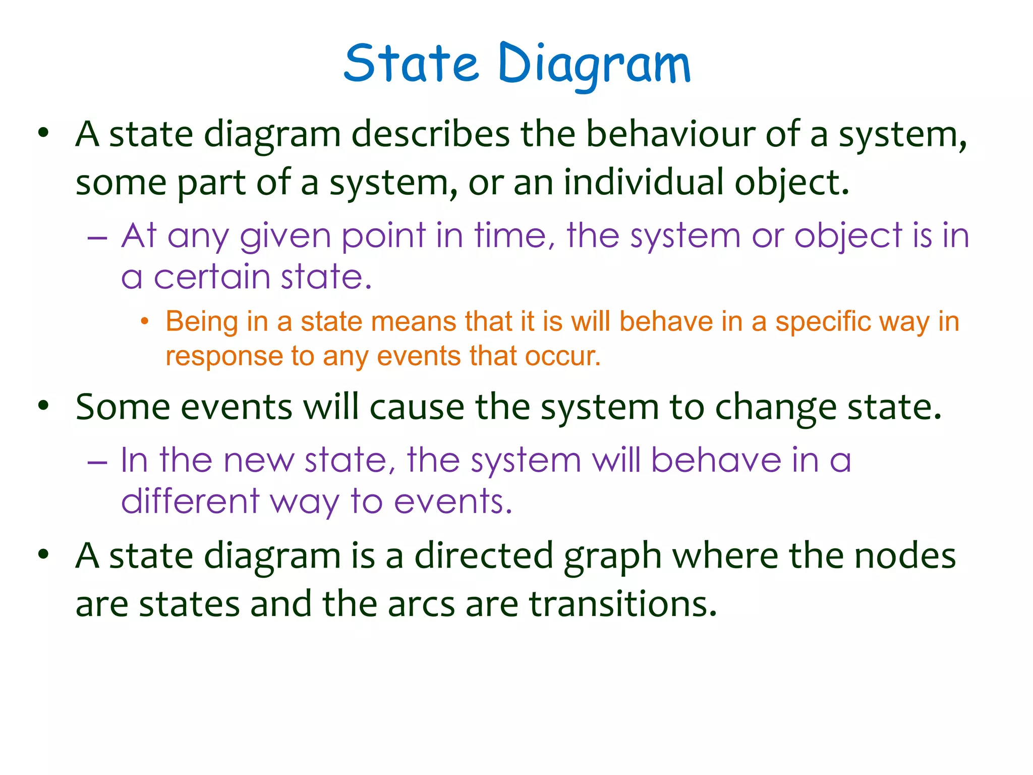
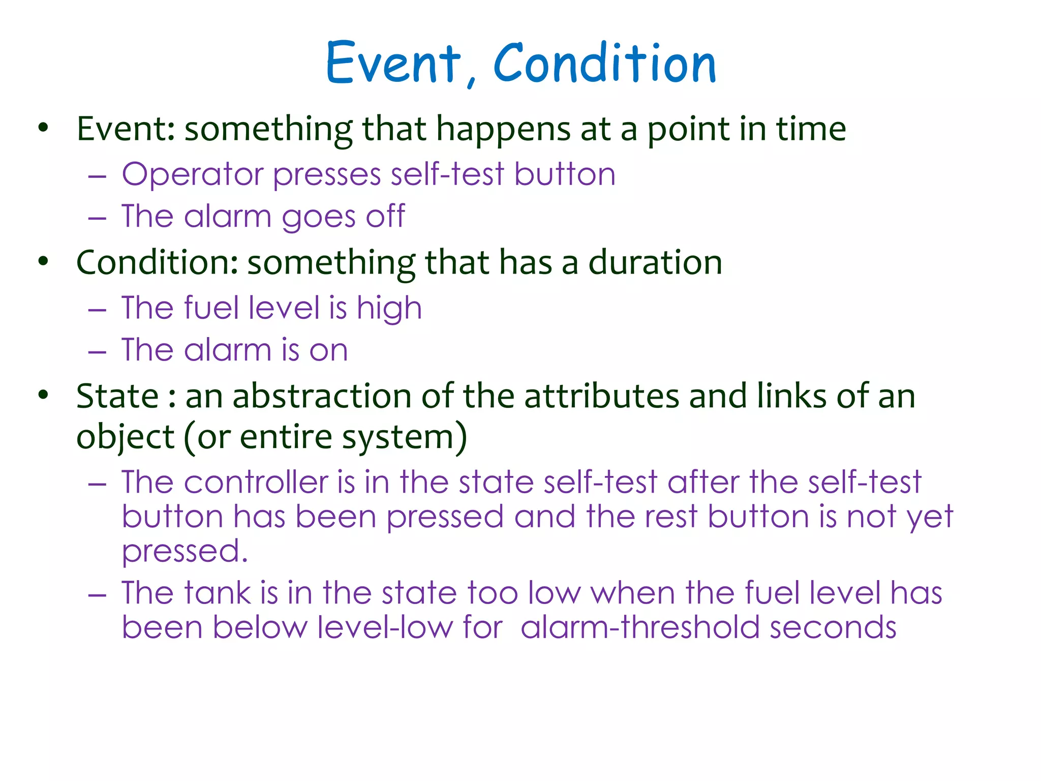
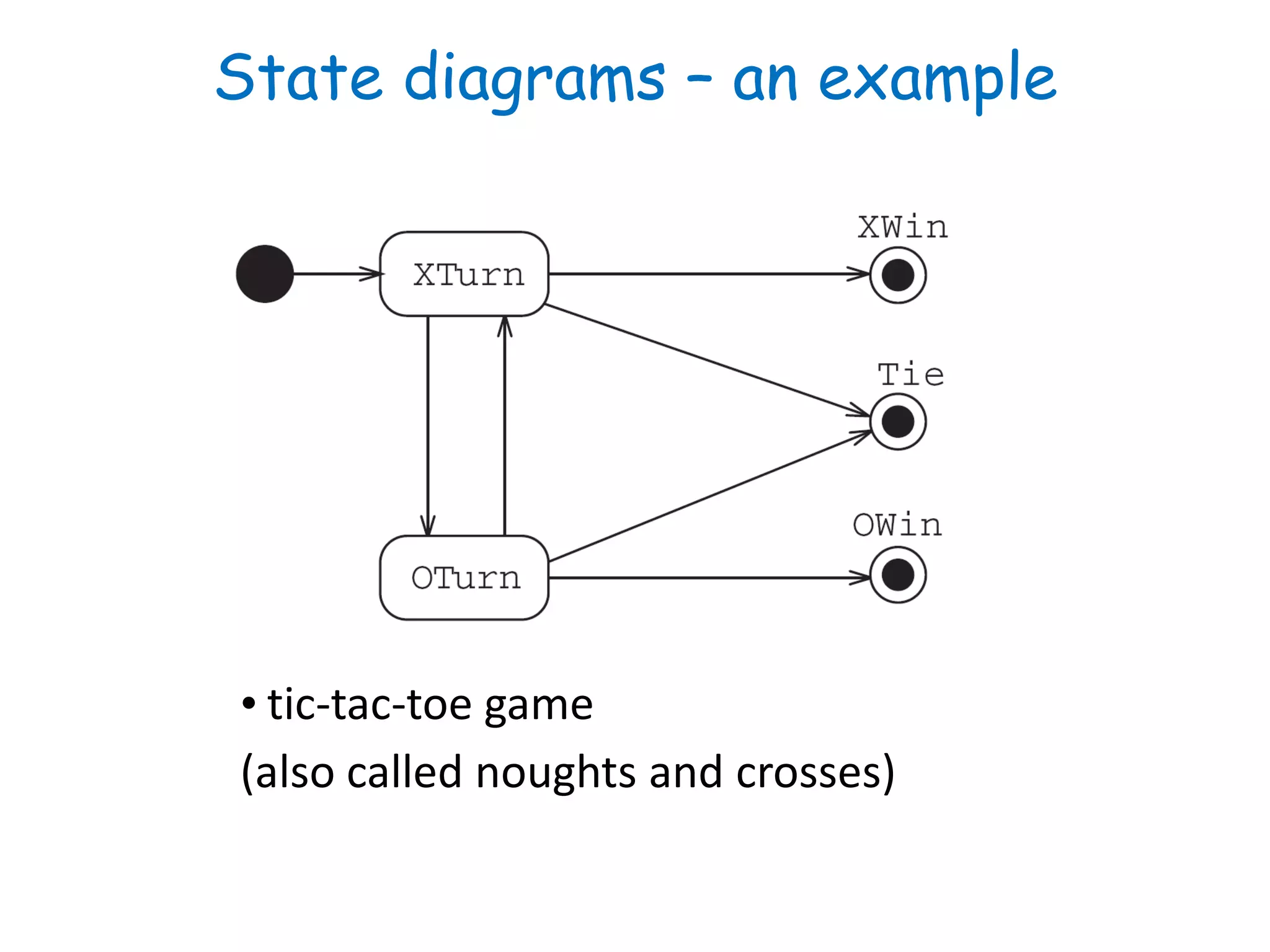
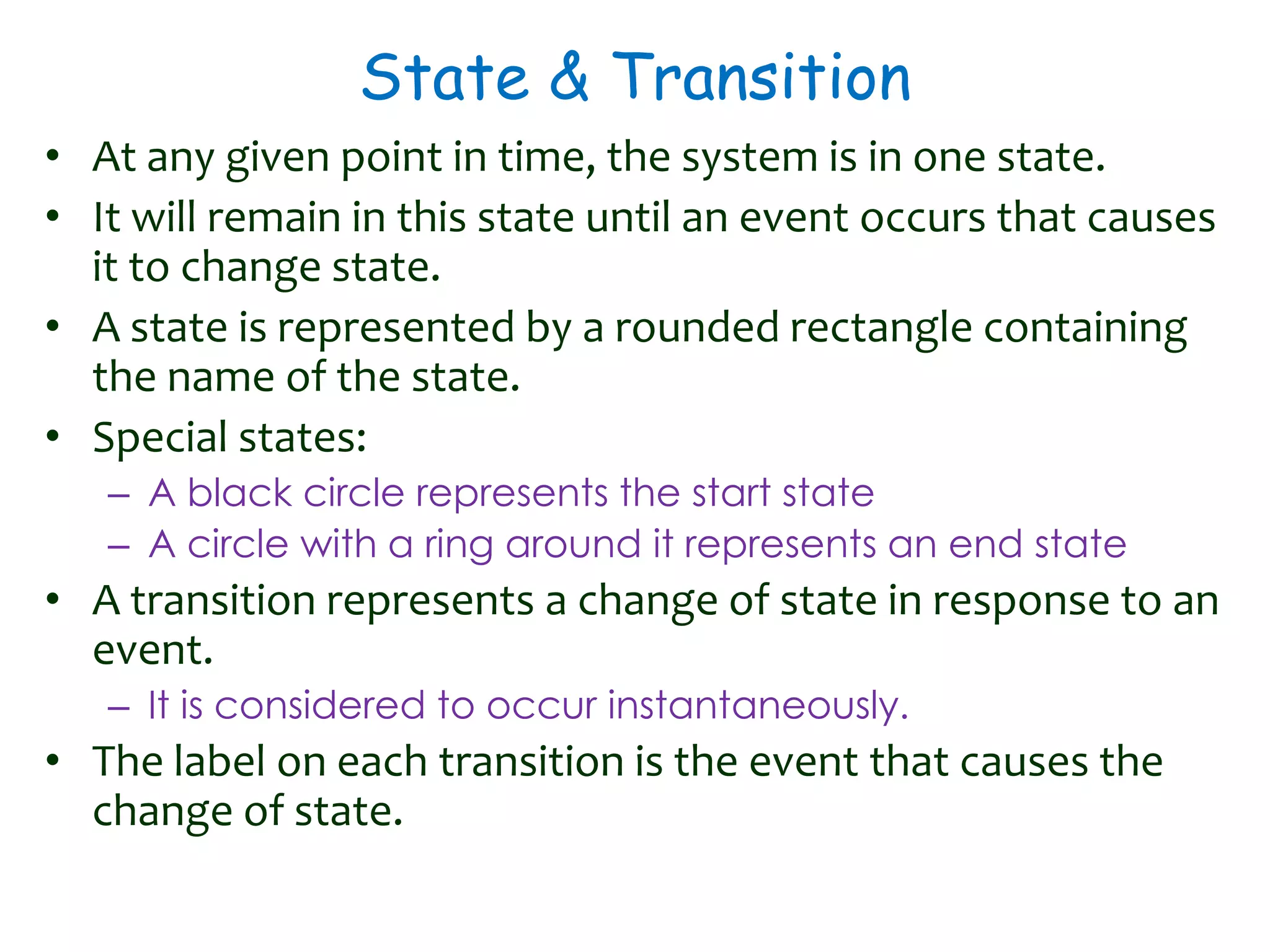
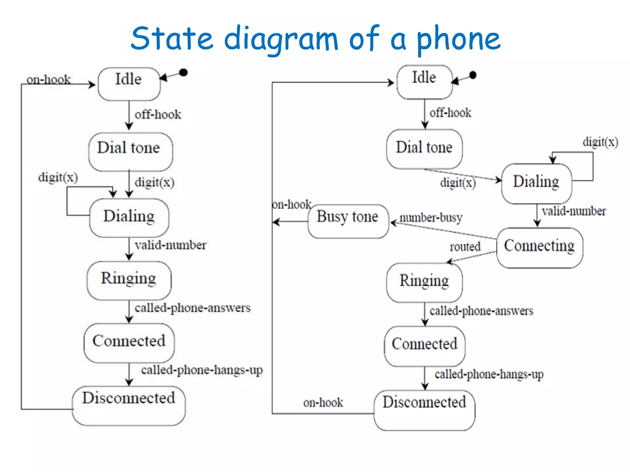
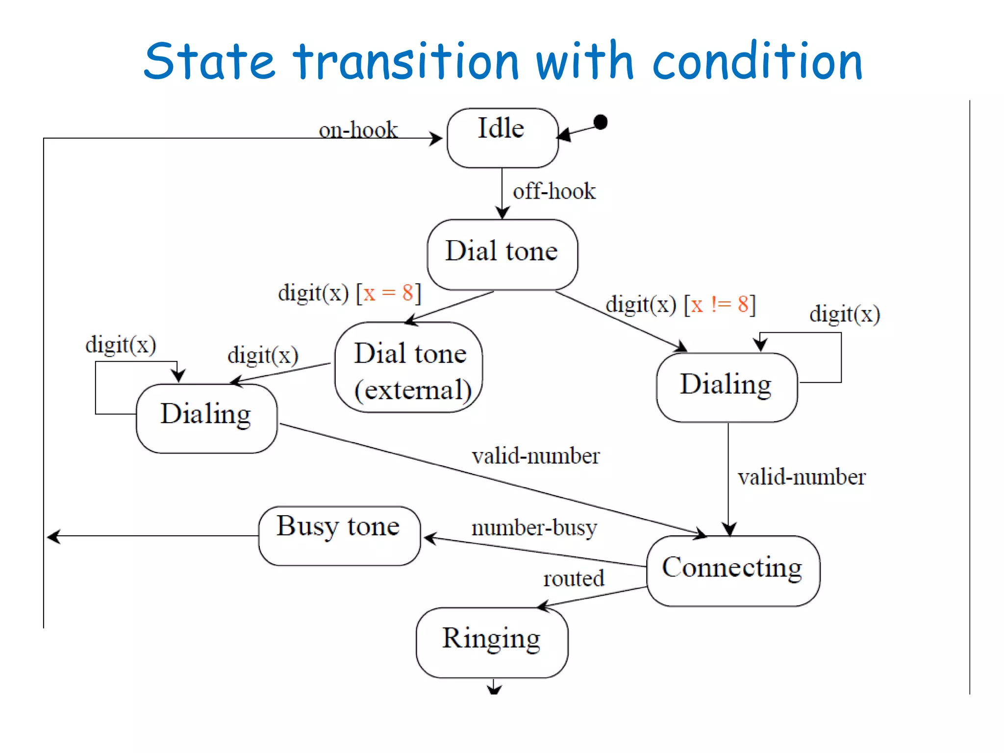
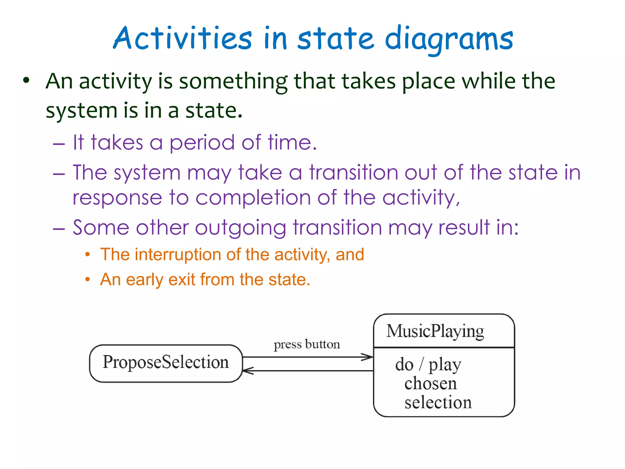

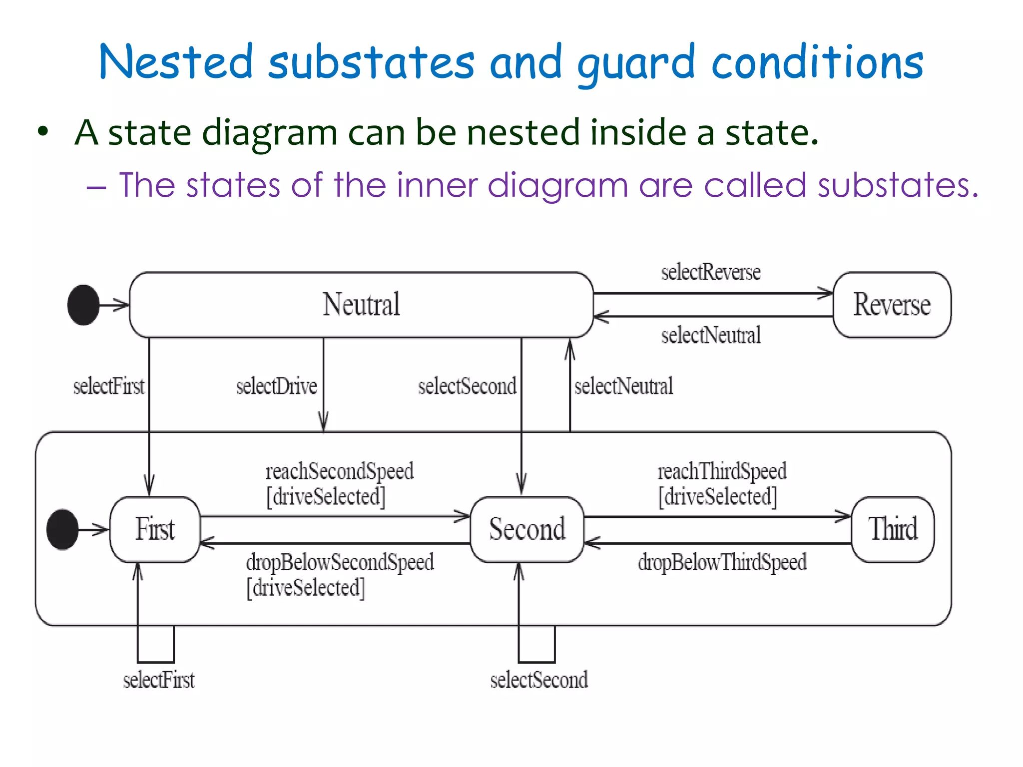
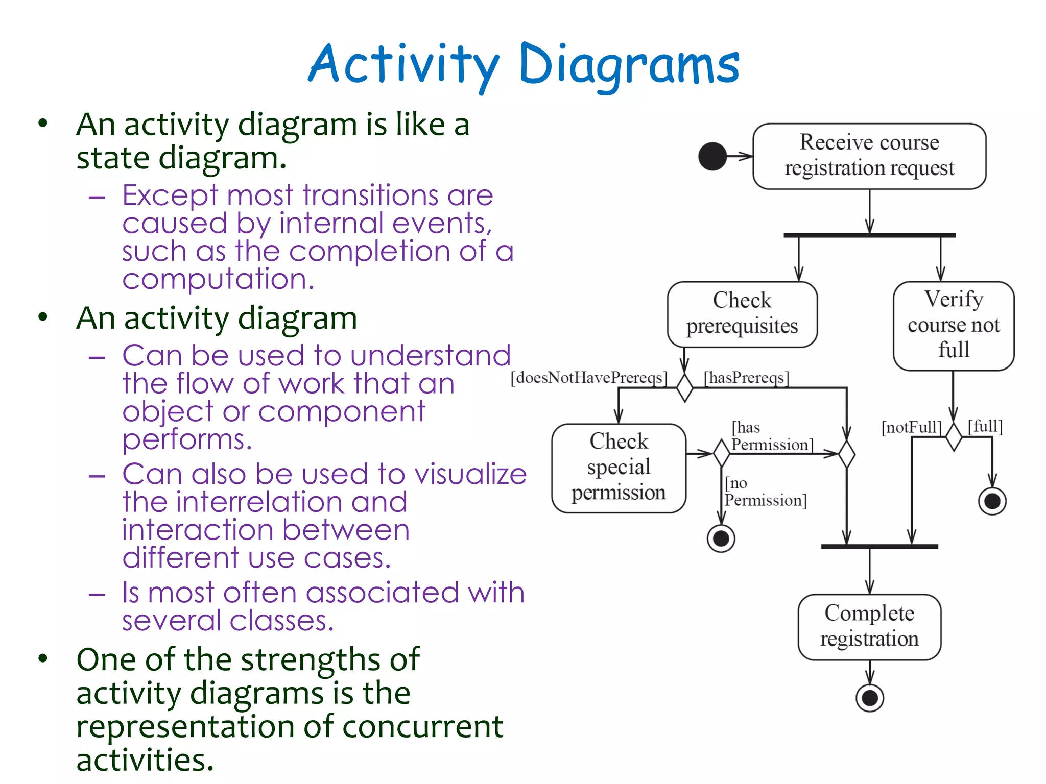
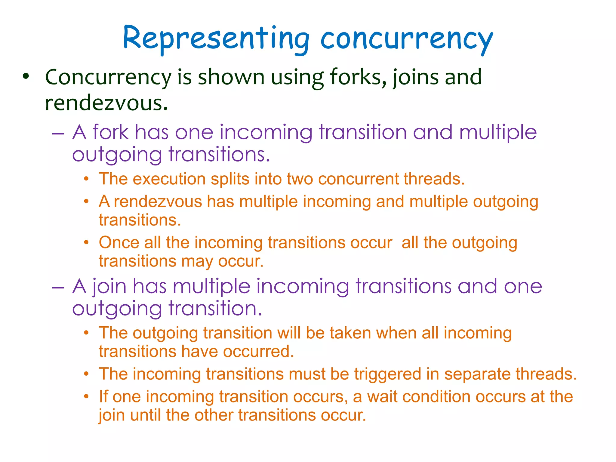
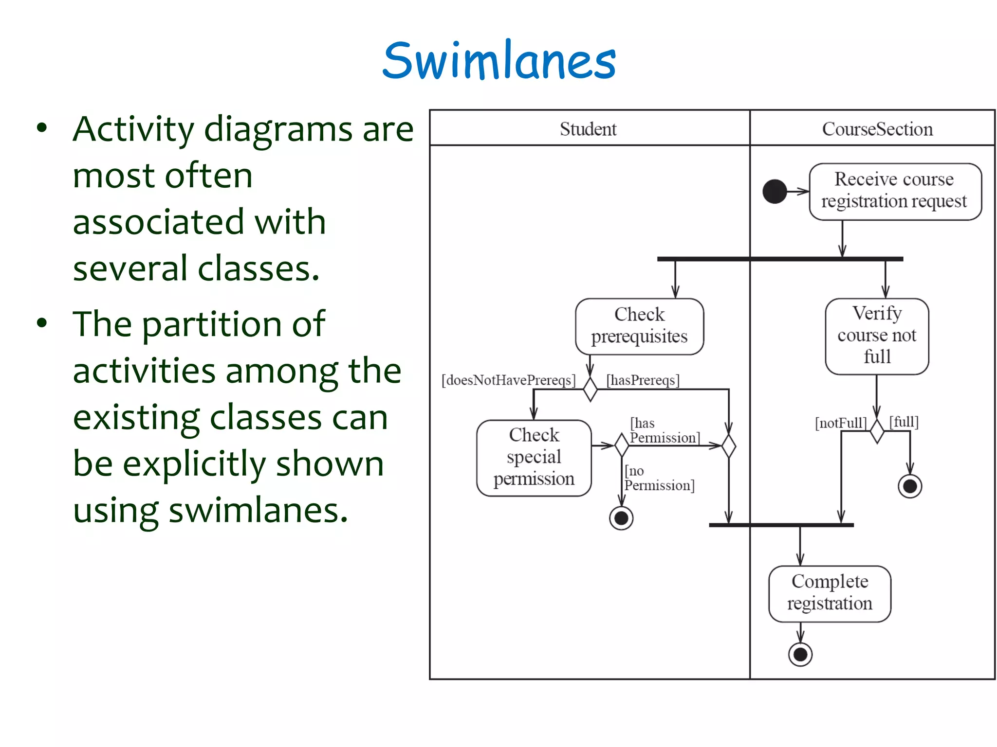
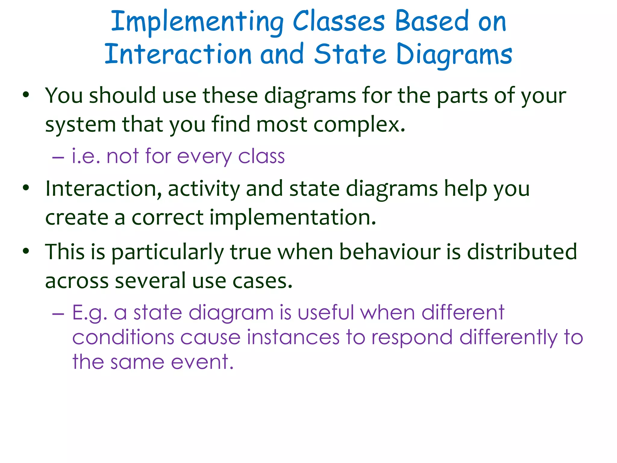
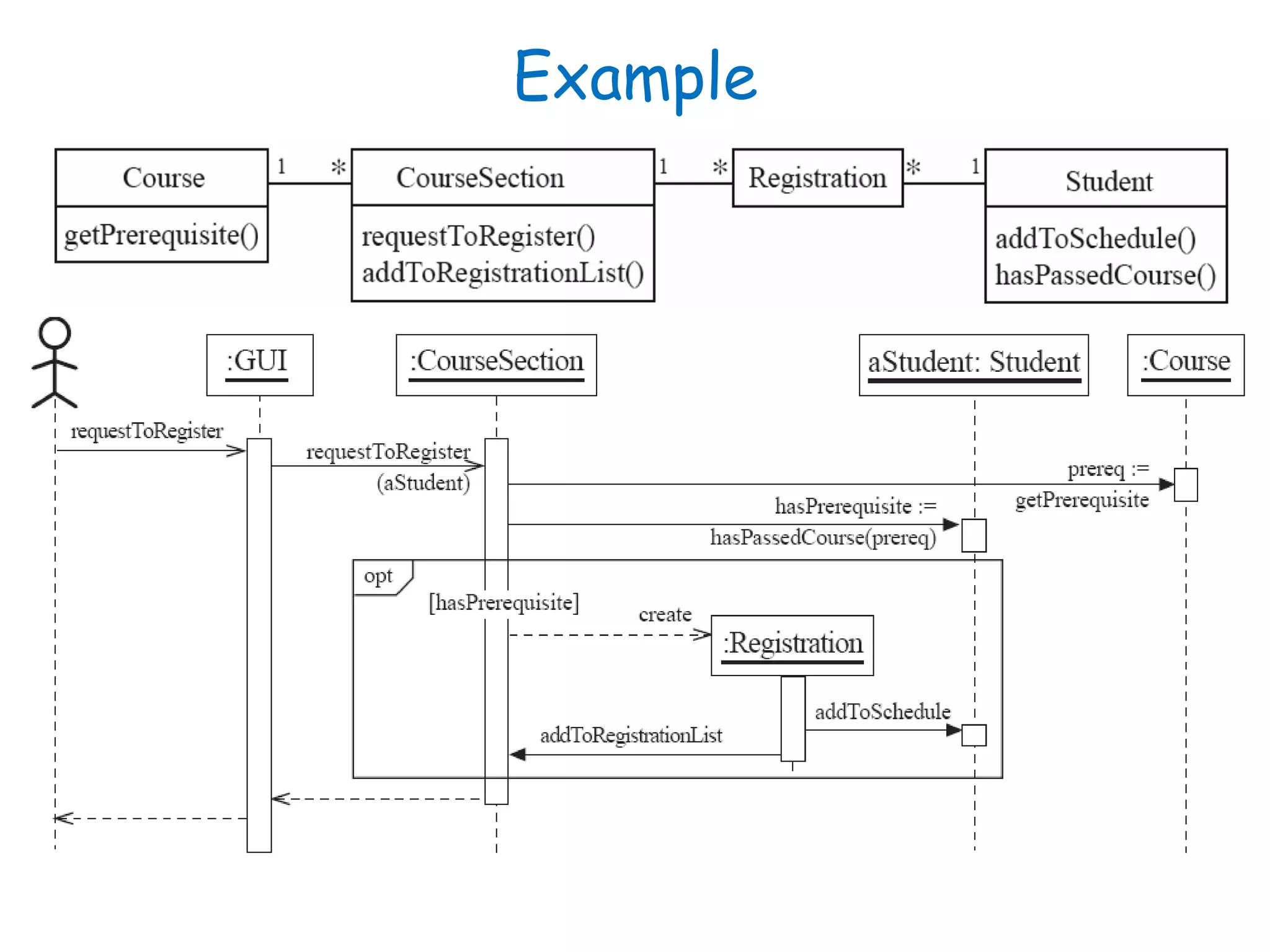
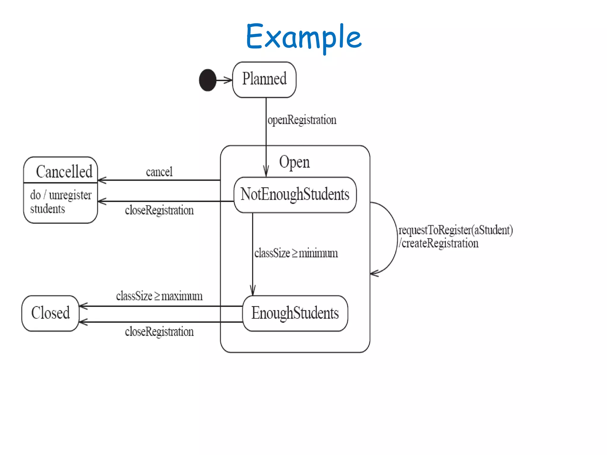
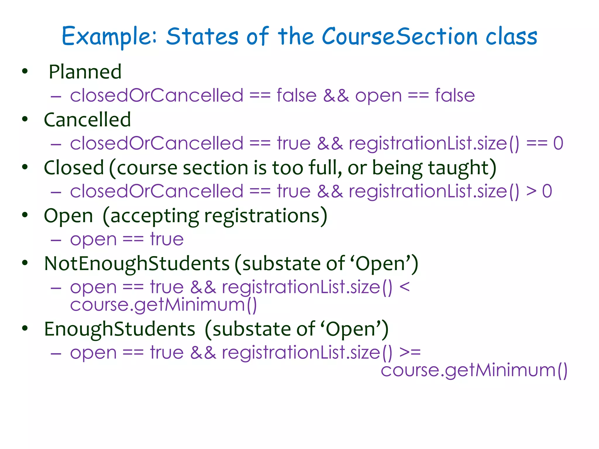
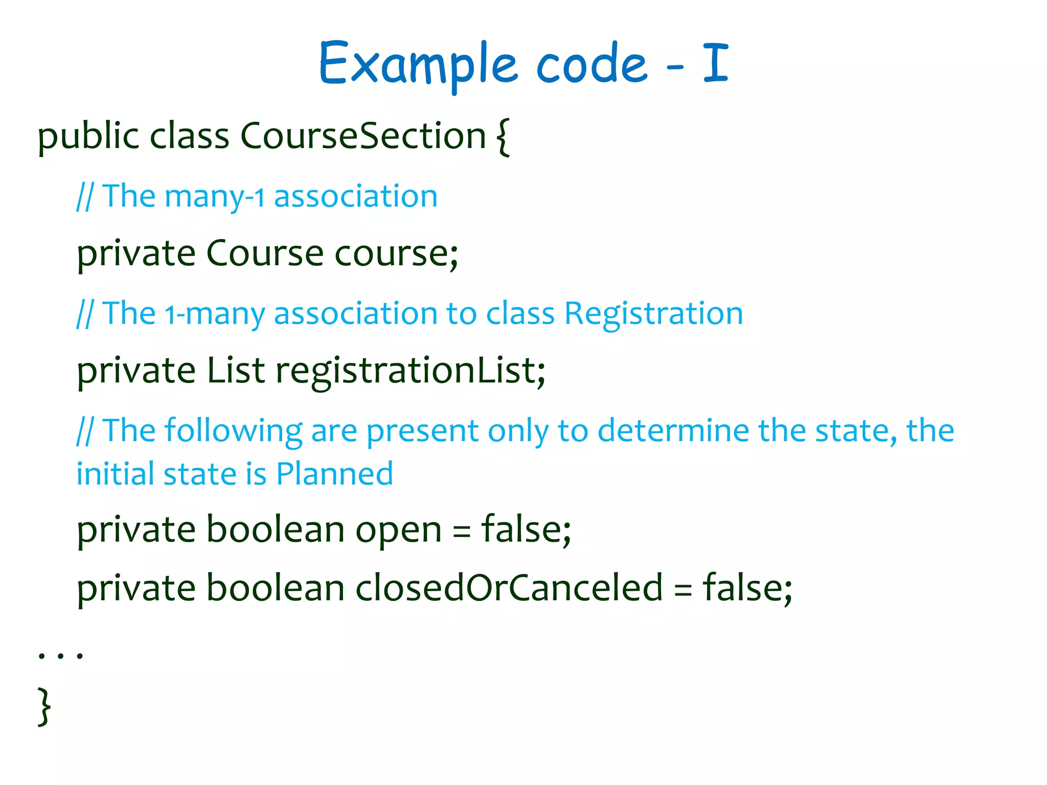
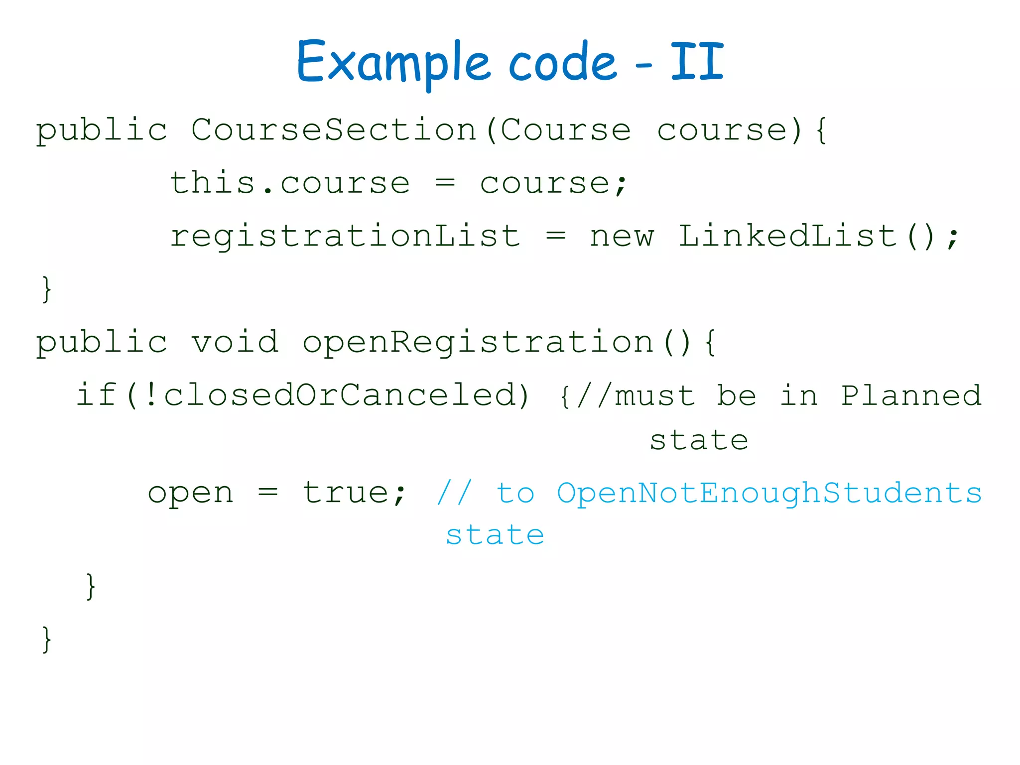
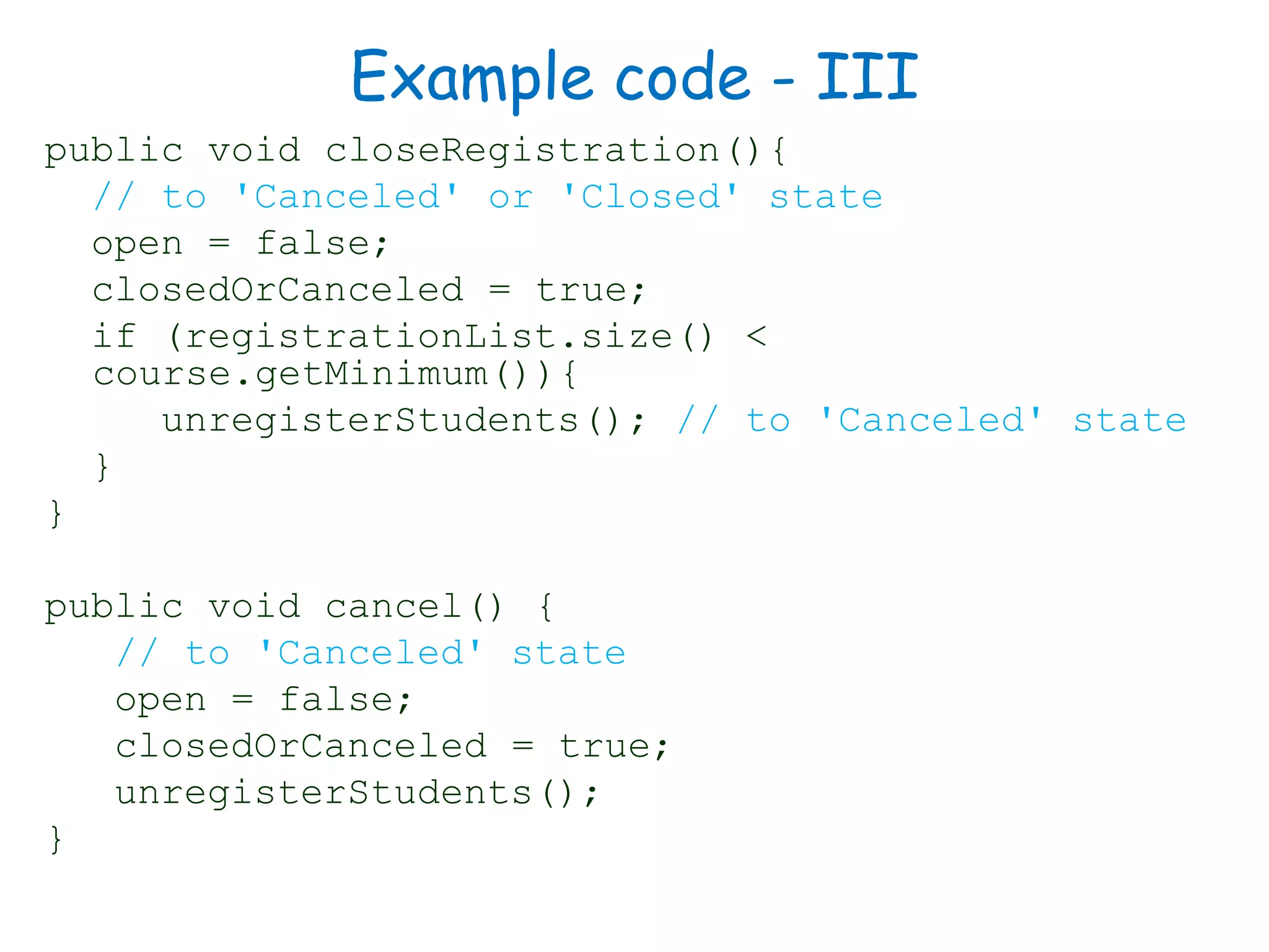
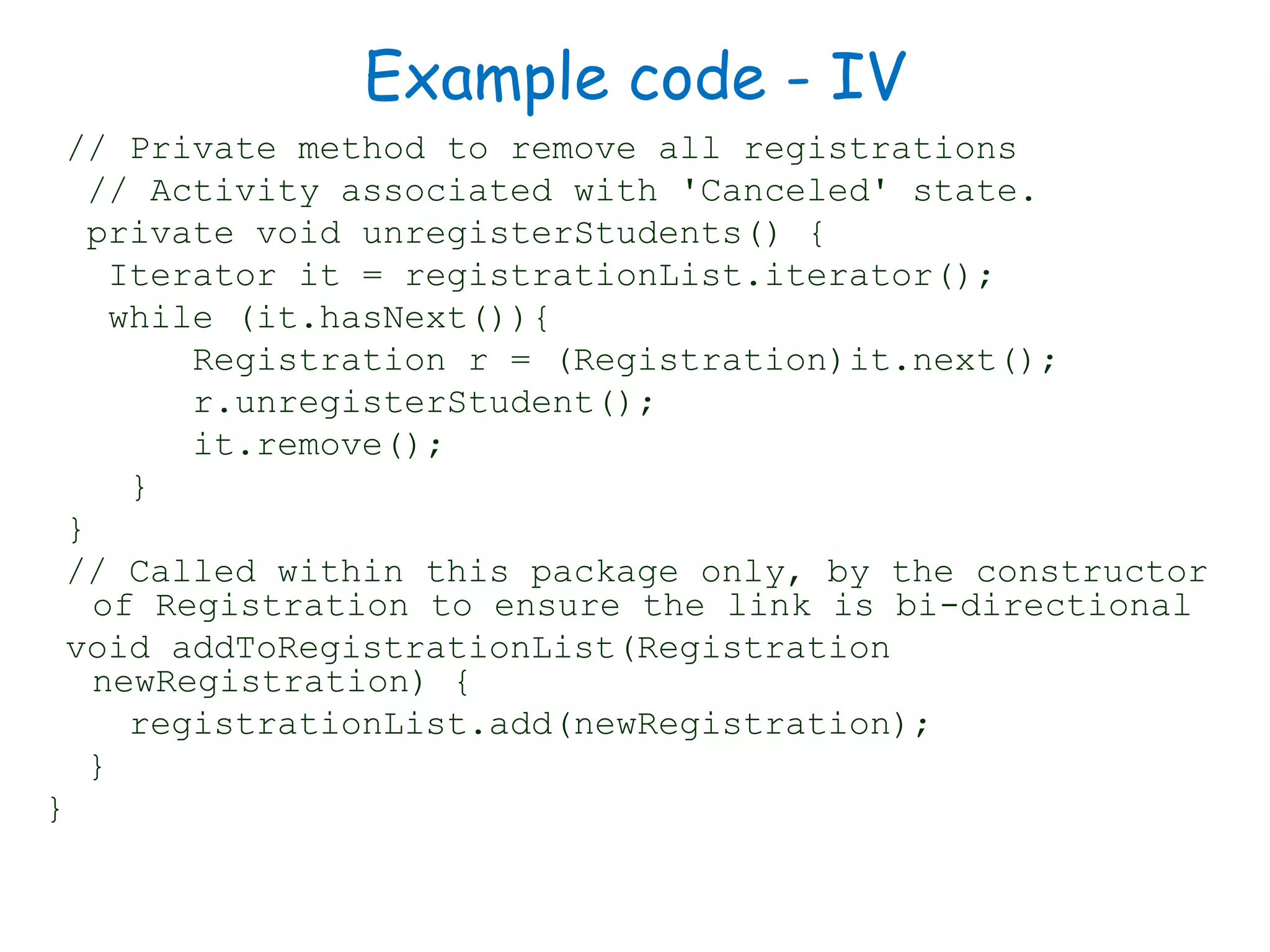


This document discusses software engineering principles related to behavioral modeling using state diagrams and activity diagrams. It provides examples and explanations of key concepts in behavioral modeling including states, events, conditions, transitions, activities, actions, concurrency, and swimlanes. It also discusses implementing classes based on interaction and state diagrams and provides an example state diagram for the states of a CourseSection class.