SlideShare a Scribd company logo
1 of 25
Download to read offline
MINNESOTA INTELLIGENT WORK ZONE TOOLBOX
2008 EDITION
Guideline for
Intelligent Work Zone
System Selection
25 MI AHEAD
EXPECT DELAYS
ROAD
WORK
BE
PREPARED
TO STOP
Minnesota
Written, compiled and illustrated by the
Minnesota Department of Transportation
Office of Traffic, Safety, and Operations
this page is intentially left blank
2008
Edition
IWZ TOOLBOX
page 1IWZ SYSTEM INTRODUCTION
Introduction:
The IWZ Toolbox has been prepared as a guideline for selecting an appropriate Intelligent Work Zone (IWZ)
System for existing work zone traffic issues and to mitigate anticipated issues on scheduled projects. The
IWZ System descriptions contained in this toolbox are intended as brainstorming material and should lead to
practical solutions to a project's unique problems. The examples are purposely left void of many
dimensions, except where particular distances are highly recommended, and engineering judgement is
required to customize the system to a project.
IWZ Systems may be sorted into 3 category types based upon detectable stimuli: "Traffic", "Vehicle", and
"Environmental". The 3 categories are shown below with their typically associated systems:
The real-time data collected for any of these systems may be combined, averaged, analyzed for
trends, and utilized for several informational uses. For example, data collected for 'Stopped Traffic
Warnings' may be to control a 'Dynamic Merge' system or to calculate "Travel Time' through a
corridor.
Traffic Responsive Systems collect and respond to average traffic characteristics such as speed an
volume of a group of vehicles and the systems react to trends of increasing/decreasing values. The
combination of these basic systems form the basis for Route Management Systems (or Traveler
Information Systems) by analyzing and reporting information in various ways. These applications may
include:
! Travel Time Information (Trip Time or Estimated Delay)
! Speed Advisory Information
! Congestion Advisory
! Stopped Traffic Advisory
! Dynamic Merge (Late or Early)
! Traffic Responsive Temporary Signals
! Temporary Ramp Metering
Vehicle Responsive Systems collect and respond to individual vehicle characteristics such as speed,
dimensions, and location. When adverse conditions are detected by these systems, motorist need
immediate warnings for quick response. These applications may include:
! Excessive Speed Warning (including Dynamic Speed Display Signs)
! Over Dimension Warning
! Work Space / Haul Road Intrusion Warning
! Construction Vehicle Warnings
Environmentally Responsive Systems collect and respond to changing non-traffic conditions of
weather, roadway or working characteristics such as visibility conditions or roadway surface conditions
and hazards. These applications may include:
! Hazardous Condition Warnings (Flooding, Ice, Fog, Smoke, Dust, etc.)
Temporary Traffic Control Devices may be equipped with advanced communication and/or remote
control capabilities which that do not react "intelligently" to detectable field data, but the devices
provide safer working conditions or improve incident response. Although these devices may not be
"Intelligent", they have been included in the IWZ Toolbox as additional safety tools for consideration
when an IWZ System is being deployed. These applications may include:
! Changeable Work Zone Signage (WZ Speed Limit Signs)
! Traffic Surveillance Cameras (removed from Toolbox)
2008
Edition
TOOLBOX COMPONENTS
Detection Components: The detectors may include: System Analysis Components: analysis algorithms
are designed or modified for each application of an! Radar
IWZ System to fit the conditions of the project.
! Pneumatic Road Tubes Algorithms can be designed with apparent limitations
and strengths, and field testing is necessary to ensure! Light Beams
the quality of the data analysis.
! Acoustical
! Ultrasonic
Data Management Components: the storage of data
! Magnetic and analysis of the data for various trends, events, etc.
may utilize many different database systems.! Piezo-Electric
! Video
Dynamic Informational Components: dynamic! RFID
components provide information to the motorists and
! Probe Injection Technologies, etc. may include:
System Monitoring Components: typical ! 511 Systems (internet & phone/cell phone),
redundancies should be built into most systems (based
! Changeable message signs (CMS) in dynamicupon risk assessment for the system failure) and the
mode,various types of quality control testing or system
monitoring may be utilized. ! Static signs with dynamic features,
System Communication Components: the typical ! Remotely activated traffic control devices,
forms of transmitting data, some of these may include:
! Audible or visual alarms,
! Cell Phones
! Real-time highway advisory radio (HAR),
! Internet - Wireless Access Points
! Public media announcements,
! Radio
! CB Radio, etc.
! Hard wired
! Optical, etc.
IWZ TOOLBOX
page 2
Typical System Components:
Each IWZ System in the Toolbox is a collection of standard system components which have been combined to
produce a useful real-time system. The individual component functions include the collection of data, verifying
the accuracy of the data, transmitting the data, storing and managing the data, analyzing the data, and/or
providing the data to the motorist.
Supplementing Existing System Components:
Mn/DOT, through it’s Regional Transportation Management Center (RTMC) and out-state TOCC’s, has the
capability to provide a variety of IWZ Systems for Mn/DOT construction and maintenance projects.
However, Mn/DOT’s detection devices, communications networks or traveler information systems may not
be adequate for a proposed IWZ System. Discrepancies may be due to construction interrupting permanent
installations, or that the existing system components do not extend to the project area.
IWZ System components provided by a contractor would supplement the services of the RTMC or TOCC’s,
when various devices/services are not currently available and may include any of the component types listed
above.
! Changeable Message Sign (CMS): a sign that is capable
of displaying more than one message, changeable
manually, by remote control, or by automatic control. The
device is considered "portable" when trailer mounted. The
device may be operated in one of two modes:
! Standard Mode: message is programmed to remain
displayed until changed by the operator or via a timer.
! Dynamic Mode: the message is programmed to
respond to traffic operating characteristics or roadway
conditions.
! Static Sign: a message for the motorist is printed on a
standard sign, either regulatory, warning or guide signs.
! Advisory Speed: a recommended speed for vehicles based
on the current roadway conditions or operating
characteristics. Advisory Speeds are not enforceable.
! Speed Limit: the speed applicable to a section of highway
as established by law.
! Travel Time: the estimated amount of drive time from the
motorist's current location to an identified location,
generally limited to approx 10 miles maximum distance.
! Travel Delay: the estimated amount of extra time the
motorist will incur due to traffic conditions in a work zone
located downstream. Generally useful for spot locations at
a great distance away from the motorist's current location,
which provides alternate route possibilities.
! Devices (components): the individual parts or subsystems
that makeup a working IWZ System. Examples include:
cameras, various detectors, signs, data monitoring or
recording equipment, communication systems, TTC
devices, and remotely activated alarms, etc.
! IWZ System: An automated system of devices that
provides motorists and/or workers real-time information
for improved safety and mobility through a work zone.
The devices are integrated to monitor traffic operating
characteristics or roadway conditions and react with a
predetermined response.
! Warrants: conditions which should be satisfied before
considering an IWZ system for deployment as part of a
project's temporary traffic control plan.
! Benefits: anticipated affects mobility and safety when the
system is properly designed and deployed. Mobility and
safety measures may be within the work zone or
surrounding network, and may include the public, the
workers, or the constructability of the project.
! Options: various options may be available for portions of
the IWZ Systems. The options should be considered when
they achieve satisfactory results with lower levels of
'system complication' and cost.
DEFINITIONS FOR USE IN THIS DOCUMENT
GENERAL IWZ TOOLBOX NOTES
SYMBOLS USED IN IWZ TOOLBOX ILLUSTRATIONS
! Changeable Message Sign
(CMS): Roadside location
symbol shown on left with an
example of two alternating
messages shown on right.
! Static Guide Sign: Roadside location
symbol shown on left with example
message shown on right.
! Static Guide Sign with CMS
Characters: Roadside location
symbol shown on left with example
message shown on right.
! Dynamic Flashing Warning Sign:
Roadside location symbol shown on
left with example message shown on
right.
! Advance Warning Sign: Roadside
location symbol shown on left with
example message shown on right.
! Non-Intrusive Detection Device: The symbol denotes
any type of detection device(s) and the actual location
and number of devices will vary from the toolbox
illustration.
! Temporary Traffic Control (TTC) Device: The
symbols denote standard TTC devices as defined by
the MN MUTCD and the Field Manual of TTC
Layouts. To highlight the IWZ systems, only a
minimal amount of TTC devices have been shown on
the toolbox illustrations. Key devices shown may
include standard warning signs, Type III barricades,
channelizing devices and flashing arrow panels.
TOOLBOX SYMBOLS and TERMINOLOGY
BE
PREPARED
TO STOP
WHEN FLASHING
ROAD
WORK
AHEAD
5 MI AHEAD
EXPECT DELAYS
ROAD
WORK
BE
PREPARED
tO STOP
BE
PREPARED
tO STOP
STOPPED
TRAFFIC
1 MILE
STOPPED
TRAFFIC
1 MILE
WORK ZONE
VEHICLES
ONLY
! Advance warning signs and other standard temporary traffic
control devices have not been shown on this figure. Refer to
the MN MUTCD including the 2007 Field Manual or the
TTC Layout Templates for typical layout examples.
! All IWZ Guide Signs and CMS should be reviewed by the
Mn/DOT Office of Traffic, Safety, & Operations for design
and message approval.
! Approved CMS messages should be listed in the Special
Provisions, and approx CMS locations should shown on the
TTC plans. All CMS displays should be blank when messages
are not warranted.
! Refer to the Toolbox Definitions Section for graphic symbols
and terms.
! Toolbox Illustrations are NOT Drawn to Scale.
IWZ TOOLBOX
page 3
2008
Edition
Note: The IWZ Toolbox Sheets contained within this document are preliminary illustrations and
may not accurately represent all the IWZ Systems as typically deployed.
The systems may be combined, modified, enhanced or simplified as necessary for a
particular project. Please use these toolbox sheets to brainstorm IWZ possibilities, and
consider what conditions may be needed to make the application viable. When a system
is deployed, we hope to quantify these conditions further, with refined warrants on the
system's toolbox sheet. We also wish to quantify benefits derived from the deployments
where ever possible in addition to the intuitive benefits that may be reaped from the IWZ
systems.
IWZ TOOLBOX
page 4TOOLBOX INDEX2008
Edition
IWZ SYSTEMS LISTED IN THIS PUBLICATION
! Travel Time Information - Trip Time or Estimated Delay
! Speed Advisory Information
! Congestion Advisory
! Stopped Traffic Advisory
! Dynamic Merge - Late or Early
! Traffic Responsive Temporary Signals
! Temporary Ramp Metering
! Excessive Speed Warning - incl. Dynamic Speed Display Signs
! Over Dimension Warning
! Work Space / Haul Road Intrusion Warning
! Construction Vehicle Warnings - Merging, Crossing & Exiting
! Hazardous Condition Warnings - Road Surface or Visibility
! Changeable Work Zone Signage - incl. WZ Speed Limits
!
Intelligent
Work Zone
Systems
Toolbox
WARRANTS BENEFITS
OPTIONSLayouts are NOT drawn to scale.
NOTES
! Advance warning signs and other standard
temporary traffic control devices have not
been shown on this figure. Refer to the MN
MUTCD including the 2007 Field Manual
or the TTC Layout Templates for typical
layout examples.
! All IWZ Guide Signs and CMS should be
reviewed by the Mn/DOT Office of Traffic,
Safety, & Operations for design and
message approval.
! Approved CMS messages should be listed
in the Special Provisions, and approx CMS
locations should shown on the TTC plans.
All CMS displays should be blank when
messages are not warranted.
! Refer to the Toolbox Definitions Section for
graphic symbols and terms.
! The work zone may cause 15 minutes or more of additional
travel time.
! The work zone causing the delay is within 10 miles of the
CMS location.
!
!
The system should inform the drivers what the estimated
travel time is between their current location and a specific
destination beyond them (up to 10 miles maximum).
The system will give drivers information which will allow
them to decide whether to change routes, provide them
opportunity to notify others of their estimated arrival time,
and generally provide drivers sufficient information to
calm tempers.
TRAVEL TIME INFORMATION
TRAFFIC
RESPONSIVE
! The CMS may be replaced with static
warning signs equipped with two (2) CMS
characters in dynamic mode. The
characters would display the real-time
travel time in the work zone downstream.
! Consideration should be given to posting
an alternate route and travel time for
additional driver information.
! The CMS may be supplemented with other
informational devices such as Highway
Advisory Radio (HAR).
WORK ZONE
CAUSING
DELAY
TIME TO
HWY CC
35 MIN
TIME TO
HWY CC
35 MIN
Distance from sign
to the destination is
limited to approx.
10 miles for accuracy
HWY CC
HWY BB
OR
Optional
Signing
Consideration should be given to posting
an alternate route and travel time for
additional driver information.
Intelligent
Work Zone
Systems
Toolbox
Last
Revision
Date:
WARRANTS BENEFITS
OPTIONSLayouts are NOT drawn to scale.
04-29-08
NOTES
! Advance warning signs and other standard
temporary traffic control devices have not
been shown on this figure. Refer to the MN
MUTCD including the 2007 Field Manual
or the TTC Layout Templates for typical
layout examples.
! All IWZ Guide Signs and CMS should be
reviewed by the Mn/DOT Office of Traffic,
Safety, & Operations for design and
message approval.
! Approved CMS messages should be listed
in the Special Provisions, and approx CMS
locations should shown on the TTC plans.
All CMS displays should be blank when
messages are not warranted.
! Refer to the Toolbox Definitions Section for
graphic symbols and terms.
ESTIMATED TRIP TIME
Intelligent
Work Zone
Systems
Toolbox
WARRANTS BENEFITS
OPTIONSLayouts are NOT drawn to scale.
NOTES
! Advance warning signs and other standard
temporary traffic control devices have not
been shown on this figure. Refer to the MN
MUTCD including the 2007 Field Manual
or the TTC Layout Templates for typical
layout examples.
! All IWZ Guide Signs and CMS should be
reviewed by the Mn/DOT Office of Traffic,
Safety, & Operations for design and
message approval.
! Approved CMS messages should be listed
in the Special Provisions, and approx CMS
locations should shown on the TTC plans.
All CMS displays should be blank when
messages are not warranted.
! Refer to the Toolbox Definitions Section for
graphic symbols and terms.
! The work zone may cause 15 minutes or more of additional
travel time.
! The work zone causing the delay is located more than 10
miles beyond the CMS location (preferably 25 to 50 miles
or more, such that multiple alternate routes are available).
!
!
System should inform the drivers what the estimated delay
time is at an approximate location along the roadway
downstream. The delay is calculated based upon queue
speeds vs. normal travel speeds.
The system will give drivers information which will allow
them to decide whether to change routes, provide them
opportunity to notify others of their estimated arrival time,
and generally provides drivers sufficient information
to calm tempers when they arrive at the cause of the delay.
TRAVEL DELAY INFORMATION
! The CMS may be replaced with static
warning signs equipped with two (2) CMS
characters in dynamic mode. The
characters would display the real-time
travel delay in the work zone downstream.
!
!
Consideration should be given to posting
an alternate route and travel time for
additional driver information.
The system may be converted to a Travel
Time system within 10 miles of the
destination location (such as Hwy CC in
this example).
! The CMS may be supplemented with other
informational devices such as Highway
Advisory Radio (HAR).
WORK ZONE
CAUSING
DELAY
sign located
approx 800
feet before CMS
sign located
approx 800
feet before CMS
EXPECT
25 MIN
DELAY
EXPECT
25 MIN
DELAY
ROAD
WORK AT
HWY CC
ROAD
WORK AT
HWY CC
EXPECT
25 MIN
DELAY
EXPECT
25 MIN
DELAY
ROAD
WORK AT
HWY CC
ROAD
WORK AT
HWY CC
Non-Intrusive Detection spaced along
the route as needed for proper system
operations. Detection should extend
beyond limits of work zone congestion.
Multiple CMS locations may be deployed
depending upon availability of alternate routes.
Alternate Route Exit
HWY CC
HWY BB
Intelligent
Work Zone
Systems
Toolbox
Last
Revision
Date:
WARRANTS BENEFITS
OPTIONSLayouts are NOT drawn to scale.
04-29-08
NOTES
! Advance warning signs and other standard
temporary traffic control devices have not
been shown on this figure. Refer to the MN
MUTCD including the 2007 Field Manual
or the TTC Layout Templates for typical
layout examples.
! All IWZ Guide Signs and CMS should be
reviewed by the Mn/DOT Office of Traffic,
Safety, & Operations for design and
message approval.
! Approved CMS messages should be listed
in the Special Provisions, and approx CMS
locations should shown on the TTC plans.
All CMS displays should be blank when
messages are not warranted.
! Refer to the Toolbox Definitions Section for
graphic symbols and terms.
TRAFFIC
RESPONSIVE
ESTIMATED DELAY TIME
Intelligent
Work Zone
Systems
Toolbox
WARRANTS BENEFITS
OPTIONSLayouts are NOT drawn to scale.
NOTES
! Advance warning signs and other standard
temporary traffic control devices have not
been shown on this figure. Refer to the MN
MUTCD including the 2007 Field Manual
or the TTC Layout Templates for typical
layout examples.
! All IWZ Guide Signs and CMS should be
reviewed by the Mn/DOT Office of Traffic,
Safety, & Operations for design and
message approval.
! Approved CMS messages should be listed
in the Special Provisions, and approx CMS
locations should shown on the TTC plans.
All CMS displays should be blank when
messages are not warranted.
! Refer to the Toolbox Definitions Section for
graphic symbols and terms.
! The work zone will cause additional travel time.
! The work zone queue is estimated to slow traffic at least 20 mph below the
posted speed limit.
!
!
!
The system should advise drivers of an appropriate vehicle speed to allow
them to travel through the work zone with minimal braking.
The system will smooth the transition between faster and slower moving
traffic.
The system should provide an increase in capacity of the roadway
through the work zone area.
SPEED ADVISORY INFORMATION
! The CMS may be replaced with static
warning signs equipped with two (2) CMS
characters in dynamic mode. The characters
would display the real-time average speed
in the work zone downstream.
OPTIONAL DESIGN:
combination of static sign
and digital number display
WORK ZONE
CAUSING
DELAY
QUEUE
OF SLOWED
TRAFFIC
30 MPH
TRAFFIC
AHEAD
30 MPH
TRAFFIC
AHEAD
WATCH
FOR SLOW
TRAFFIC
WATCH
FOR SLOW
TRAFFIC
Non-Intrusive Detection spaced along
the route as needed for proper system
operations. Detection should extend
beyond limits of work zone congestion.
The CMS should be located 2 - 3 miles before the
slow traffic queue. The displayed speed is the
average speed detected entering the work zone
location. Based upon this information, the motorist
may adjust speed to anticipate the slower traffic.
Intelligent
Work Zone
Systems
Toolbox
Last
Revision
Date:
WARRANTS BENEFITS
OPTIONSLayouts are NOT drawn to scale.
04-29-08
NOTES
! Advance warning signs and other standard
temporary traffic control devices have not
been shown on this figure. Refer to the MN
MUTCD including the 2007 Field Manual
or the TTC Layout Templates for typical
layout examples.
! All IWZ Guide Signs and CMS should be
reviewed by the Mn/DOT Office of Traffic,
Safety, & Operations for design and
message approval.
! Approved CMS messages should be listed
in the Special Provisions, and approx CMS
locations should shown on the TTC plans.
All CMS displays should be blank when
messages are not warranted.
! Refer to the Toolbox Definitions Section for
graphic symbols and terms.
TRAFFIC
RESPONSIVE
Intelligent
Work Zone
Systems
Toolbox
Last
Revision
Date:
WARRANTS
NOTES
BENEFITS
OPTIONS
Non-Intrusive Detection spaced along the route
as needed for proper system operations
OR
OR
Optional
Signage
WORK ZONE
CAUSING
DELAY
Example messages:
When an alternate route
exists prior to the queue.
Example messages:
When no alternate routes
are available prior to the
queue.
! When queues are estimated to never
extend to the CMS location, the CMS may
be replaced with a static warning sign
equipped with two dynamic CMS
characters for mileage. When no queues
are detected, the mileage display would
correspond with the accompanying guide
sign for "Road Work XX Mi Ahead".
CONGESTION ADVISORY
! When traffic queue lengths are reasonably
predictable, warning motorists of stopped /
slowed traffic may be accomplished with
the use of typical TTC warning signs
placed prior to the anticipated beginning of
queue.
! The system may be combined with
"Dynamic Merge", "Stopped Traffic
Warning" and "Travel Time and/or Delay"
systems.
Layouts are NOT drawn to scale.
BE
PREPARED
tO STOP
BE
PREPARED
tO STOP
STOPPED
TRAFFIC
1 MILE
STOPPED
TRAFFIC
1 MILE
5 MI AHEAD
EXPECT DELAYS
ROAD
WORK
BE
PREPARED
tO STOP
BE
PREPARED
tO STOP
STOPPED
TRAFFIC
11 MILES
STOPPED
TRAFFIC
11 MILES
CONSIDER
other
ROUTES
CONSIDER
other
ROUTES
15 MI AHEAD
EXPECT DELAYS
ROAD
WORK
STOPPED
TRAFFIC
11 MILES
STOPPED
TRAFFIC
11 MILES
25 MI AHEAD
EXPECT DELAYS
ROAD
WORK
CONSIDER
other
ROUTES
CONSIDER
other
ROUTES
STOPPED
TRAFFIC
21 MILES
STOPPED
TRAFFIC
21 MILES
10-01-07
! Queue lengths are estimated to vary greatly, day-by-day and hour-by-hour
such that a suitable location for the TTC advance warning signage can not
be predicted. Note: signs placed more than a mile ahead of confirmation
are typically forgotten by the motorist.
! Queue lengths may encroach upstream beyond a motorist's reasonable
expectations for stopped traffic and there is probability that the geometrics
(terrain) may cause poor visibility of end of traffic queues, causing short
reaction times and panic stopping.
! The queue is estimated to stop downstream of the last CMS in the system.
! The system should
!
alert drivers of an upcoming traffic slow-down or
stopped traffic, providing time to determine possible route alternates, and
to be prepared to stop safely.
Traffic may divert to alternate routes.
! Advance warning signs and other standard
temporary traffic control devices have not
been shown on this figure. Refer to the MN
MUTCD including the 2007 Field Manual
or the TTC Layout Templates for typical
layout examples.
! All IWZ Guide Signs and CMS should be
reviewed by the Mn/DOT Office of Traffic,
Safety, & Operations for design and
message approval.
! Approved CMS messages should be listed
in the Special Provisions, and approx CMS
locations should shown on the TTC plans.
All CMS displays should be blank when
messages are not warranted.
! Refer to the Toolbox Definitions Section for
graphic symbols and terms.
800 ft. apart
800 ft. apart
800 ft. apart
STO P P ED TRAFFI C
M I LES AH EAD
2 1
STO P P ED TRAFFI C
M I LES AH EAD
2 1
OPERATIONAL NOTES:
! When no queue is detected, all the CMS should
be blank unless used for another IWZ system.
! When the queue approaches within one mile of
any CMS, the CMS should operate as a "Stopped
Traffic Advisory" device.
! When the queue extends beyond any CMS
location, the CMS should be blank, or it may be
utilized for another IWZ system such as DLM.
Queue
length
for this
example
(4 miles)
TRAFFIC
RESPONSIVE
Intelligent
Work Zone
Systems
Toolbox
Last
Revision
Date:
WARRANTS
NOTES
BENEFITS
OPTIONS
! The CMS may be replaced with an
appropriate warning sign equipped with
dynamically automated flashing lights as
shown below.
! The static signs are spaced incrementally
and the individual flashers are activated in
response to queued traffic when the queue
is detected within one mile of the sign
location.
! When traffic queue lengths are reasonably
predictable, warning motorists of stopped /
slowed traffic may be accomplished with
the use of typical TTC warning signs
placed prior to the anticipated beginning of
queue.
! The system may be combined with
"Dynamic Merge" and "Stopped Traffic
Advisory" systems
STOPPED TRAFFIC ADVISORY
Layouts are NOT drawn to scale.
B E
P R E P A R E D
T O S T O P
WHEN FLASHING
! Queue lengths are estimated to vary greatly, day-by-day and hour-by-hour
such that a suitable location for the TTC advance warning signage can not
be predicted. Note: signs placed more than a mile ahead of confirmation
are typically forgotten by the motorist.
! Queue lengths may encroach upstream beyond a motorist's reasonable
expectations for stopped traffic and there is probability that the geometrics
(terrain) may cause poor visibility of end of traffic queues, causing short
reaction times and panic stopping.
! Queues initiated on crossroads are estimated to cause traffic conflicts
and/or delays on the mainline road, such as backups beyond the length of
ramps, through or around turns in intersections, or other hazardous
congestion situations.
! The system should
!
!
alert drivers of an upcoming traffic slow-down or
stopped traffic, providing time to determine possible route alternates, and
to be prepared to stop safely.
It is anticipated that the system will reduce rear-end crashes.
Traffic may divert to alternate routes.
! Advance warning signs and other standard
temporary traffic control devices have not
been shown on this figure. Refer to the MN
MUTCD including the 2007 Field Manual
or the TTC Layout Templates for typical
layout examples.
! All IWZ Guide Signs and CMS should be
reviewed by the Mn/DOT Office of Traffic,
Safety, & Operations for design and
message approval.
! Approved CMS messages should be listed
in the Special Provisions, and approx CMS
locations should shown on the TTC plans.
All CMS displays should be blank when
messages are not warranted.
! Refer to the Toolbox Definitions Section for
graphic symbols and terms.
Non-Intrusive Detection spaced along the route
as needed for proper system operations
WORK ZONE
CAUSING
DELAY
BE
PREPARED
tO STOP
BE
PREPARED
tO STOP
STOPPED
TRAFFIC
AHEAD
STOPPED
TRAFFIC
AHEAD
Optional
Signing
OR
BE
PREPARED
tO STOP
BE
PREPARED
tO STOP
STOPPED
TRAFFIC
AHEAD
STOPPED
TRAFFIC
AHEAD
Optional
Signing
OR
BE
PREPARED
TO STOP
WHEN FLASHING
BE
PREPARED
TO STOP
WHEN FLASHING
BE
PREPARED
TO STOP
WHEN FLASHING
BE
PREPARED
tO STOP
BE
PREPARED
tO STOP
STOPPED
TRAFFIC
AHEAD
STOPPED
TRAFFIC
AHEAD
Optional
Signing
OR
The signs are spaced incrementally and are
activated in response to queued traffic when
the queue is detected within one mile of the
sign location.
As the queue extends beyond a CMS location,
the sign should switch to only the
"Prepare to Stop" message.
When no queue is detected, all the CMS
should be blank or used for another ITS system.
04-29-08
TRAFFIC
RESPONSIVE
OPTIONAL SIGN DESIGN
Intelligent
Work Zone
Systems
Toolbox
Last
Revision
Date:
! Two lanes of must merge into one direction will be closed to traffic and
traffic must merge.
! Although queues may develop at low volumes for many reasons, typically,
the volume must exceed 1500 vehicles/hour to sustain a queue that was
caused by merging lanes.
! Estimated queue lengths may encroach beyond an upstream intersection or
interchange operations.
! The speeds and lane occupancy volumes are anticipated to vary
unpredictably causing the motorist to have trouble identifying the best lane
usage practice, such as using both lanes versus moving into the continuous
thru-lane.
! The system should
!
!
!
alert drivers of an upcoming traffic slow-down or
stopped traffic, and inform them to use both lanes until the designated
merge point.
It is anticipated that the system will reduce the length of the upstream
queue by 40%, which may reduce conflicts at nearby intersections.
By utilizing both traffic lanes, the differential speed between lanes is
greatly reduced since both lanes travel at approx the same speed.
Motorists are given positive directions on lane usage and merging which
clears misunderstandings between drivers and reduces road rage.
WARRANTS BENEFITS
OPTIONS
DYNAMIC LATE MERGE
!
!
!
!
! When traffic queue lengths are reasonably
low and predictable, instructing motorists
of proper lane usage may be accomplished
with the use of typical TTC warning signs
placed prior to the anticipated beginning
of queue.
The dynamic system may be combined
with Congestion Warning and Travel Time
and/or Delay Systems.
When the speeds and lane occupancy
volumes are anticipated to increase very
predictably and hold at that a high level,
the motorist should have little trouble
identifying when the traffic is congesting
and begin to follow the posted merging
procedure, such as using both lanes. Only
clear directions on proper actions are
needed by the motorist. Two options:
The directions may be supplied on
static guide signs posted beyond the
anticipated queue length and
repeated within the queue area. An
example series of Static Signs is
shown below:
When the congestion time is highly
predictable, the directions may be
posted on CMS as shown in the
illustration, and activated by timers,
rather that traffic conditions.
Layouts are NOT drawn to scale.
USE
BOTH
LANES
USE
BOTH
LANES
STOPPED
TRAFFIC
AHEAD
STOPPED
TRAFFIC
AHEAD
USE
BOTH
LANES
USE
BOTH
LANES
MERGE
AHEAD
MERGE
AHEAD
TAKE
TURNS
TAKE
TURNS
MERGE
HERE
MERGE
HERE
MERGE
TAPER
BUFFER
Non-Intrusive Detection spaced along the route
as needed for proper system operations
CMS located beyond the estimated
maximum queue length
CMS located beyond the estimated
queue length at the time when system
activation will occur
CMS located at point of merge
The first advance warning sign should be located
before the estimated queue beginning
ROAD WO R K
15 M IL ES AH EAD
EXP ECT LO N G BACKU PS
O N WEEKEN DS
D U R I N G BACKU PS
U S E BOTH LAN ES
TAKE TU R N S AT M ERG E
NOTES
! Advance warning signs and other standard
temporary traffic control devices have not
been shown on this figure. Refer to the MN
MUTCD including the 2007 Field Manual
or the TTC Layout Templates for typical
layout examples.
! All IWZ Guide Signs and CMS should be
reviewed by the Mn/DOT Office of Traffic,
Safety, & Operations for design and
message approval.
! Approved CMS messages should be listed
in the Special Provisions, and approx CMS
locations should shown on the TTC plans.
All CMS displays should be blank when
messages are not warranted.
! Refer to the Toolbox Definitions Section for
graphic symbols and terms.
04-29-08
TRAFFIC
RESPONSIVE
Intelligent
Work Zone
Systems
Toolbox
Last
Revision
Date:
WARRANTS BENEFITS
OPTIONSLayouts are NOT drawn to scale.
NOTES
! Advance warning signs and other standard
temporary traffic control devices have not
been shown on this figure. Refer to the MN
MUTCD including the 2007 Field Manual
or the TTC Layout Templates for typical
layout examples.
! All IWZ Guide Signs and CMS should be
reviewed by the Mn/DOT Office of Traffic,
Safety, & Operations for design and
message approval.
! Approved CMS messages should be listed
in the Special Provisions, and approx CMS
locations should shown on the TTC plans.
All CMS displays should be blank when
messages are not warranted.
! Refer to the Toolbox Definitions Section for
graphic symbols and terms.
! !
SHEET UNDER DEVELOPMENT
DYNAMIC EARLY MERGE 00-00-00
TRAFFIC
RESPONSIVE
MERGE
TAPER
Non-Intrusive
Detection spaced
along the route
as needed for
proper system
operations
CMS located beyond the
estimated queue length
at the time when system
activation will occur
Always Flashing
at this Location
(within one mile)
Spaced at
¼ - ½ mile
increments
for estimated
length of
queue
The first advance warning sign
should be located before the
estimated queue beginning
MERGE
RIGHT
MERGE
RIGHT
FORM
ONE
LANE
RIGHT
LEFT LANE
CLOSED
1 MILE
Intelligent
Work Zone
Systems
Toolbox
Last
Revision
Date:
WARRANTS BENEFITS
OPTIONSLayouts are NOT drawn to scale.
10-01-07
NOTES
! Advance warning signs and other standard
temporary traffic control devices have not
been shown on this figure. Refer to the MN
MUTCD including the 2007 Field Manual
or the TTC Layout Templates for typical
layout examples.
! All IWZ Guide Signs and CMS should be
reviewed by the Mn/DOT Office of Traffic,
Safety, & Operations for design and
message approval.
! Approved CMS messages should be listed
in the Special Provisions, and approx CMS
locations should shown on the TTC plans.
All CMS displays should be blank when
messages are not warranted.
! Refer to the Toolbox Definitions Section for
graphic symbols and terms.
! !
TRAFFIC RESPONSIVE TEMPORARY SIGNALS
SHEET UNDER DEVELOPMENT
TRAFFIC
RESPONSIVE
Intelligent
Work Zone
Systems
Toolbox
Last
Revision
Date:
WARRANTS BENEFITS
OPTIONSLayouts are NOT drawn to scale.
05-01-08
NOTES
! Advance warning signs and other standard
temporary traffic control devices have not
been shown on this figure. Refer to the MN
MUTCD including the 2007 Field Manual
or the TTC Layout Templates for typical
layout examples.
! All IWZ Guide Signs and CMS should be
reviewed by the Mn/DOT Office of Traffic,
Safety, & Operations for design and
message approval.
! Approved CMS messages should be listed
in the Special Provisions, and approx CMS
locations should shown on the TTC plans.
All CMS displays should be blank when
messages are not warranted.
! Refer to the Toolbox Definitions Section for
graphic symbols and terms.
! !
TEMPORARY RAMP METERING
SHEET UNDER DEVELOPMENT
TRAFFIC
RESPONSIVE
Traffic forms two lanes,
allowing the total queue
length to be reduced.
Advance notification
of change in traffic
control may be used.
Temporary pedestal
mounted traffic signals.
Green alternates between
the two signal heads,
requiring the two lanes
to take turns.
Non-Intrusive Detection spaced
along the route as needed for
proper system operations.
Detection measures speed/capacity
of traffic and determines the cycle
length for the ramp meters.
RAMP
METERING
BEGINS
JUNE 10
Intelligent
Work Zone
Systems
Toolbox
Last
Revision
Date:
WARRANTS BENEFITS
OPTIONSLayouts are NOT drawn to scale.
NOTES
! Advance warning signs and other standard
temporary traffic control devices have not
been shown on this figure. Refer to the MN
MUTCD including the 2007 Field Manual
or the TTC Layout Templates for typical
layout examples.
! All IWZ Guide Signs and CMS should be
reviewed by the Mn/DOT Office of Traffic,
Safety, & Operations for design and
message approval.
! Approved CMS messages should be listed
in the Special Provisions, and approx CMS
locations should shown on the TTC plans.
All CMS displays should be blank when
messages are not warranted.
! Refer to the Toolbox Definitions Section for
graphic symbols and terms.
EXSESSIVE SPEED WARNING
! Traffic must reduce speed to safety negotiate a hazardous
condition such as a temporary unusually tight curve, or a
rough road surface.
! Buffer spaces and/or clear-zones should be analyzed for
possible intrusions by vehicles unable to sufficiently slow
down in time.
!
!
System should alert a driver that they have inadvertently
entered a portion of the work zone at a speed substantially
above the advisory speed limit.
The system provides sufficient time to slow down for the
hazardous condition.
Non-Intrusive Detection placed along
the roadway as needed for proper
system operations.
REDUCE
SPEED
NOW
REDUCE
SPEED
NOW
EXCEEDED
SPEED
LIMIT
EXCEEDED
SPEED
LIMIT
45
45
Example shows a reduced advisory
speed limit due to sharp curve with
either a substandard clear zone or
inadequate buffer zone for errant
vehicles.
04-29-08
VEHICLE
RESPONSIVE
A
XX
MPH
The work crew (or poor road condition) should
be visible to the driver from the point of viewing
the Advisory Speed Plaque and DSD sign display.
Preliminary studies show 500' is the optimum
distance for speed reduction, therefore, it's advised
to maintain that distance as much as practical. As
workers move within the work zone, the DSD
location should be re-positioned such that it
remains within 500 feet (min) and 2500 feet (max)
of the worker location. The distances may be
adjusted following further studies of the DSD sign
usage in work zones.
WORKER
LOCATION
500' min.
OPTIONAL:
warning sign with
speed advisory
(see note below)
When the DSD sign is utilizing an
Advisory Speed Limit, a warning sign
shall be displayed adjacent to the DSD
sign location. The Advisory Speed
Plaque may be attached to the warning
sign, or mounted on the DSD sign
device. The "YOUR SPEED" sign on
the DSD device shall be black on
flourescent orange.
When utilizing the DSD sign with either
a regulatory speed limit or work zone
speed limit, the "YOUR SPEED" sign
on the DSD device shall be black on
white. The DSD sign shall be either
placed adjacent to the posted speed
limit sign, or the appropriate speed
limit sign shall be mounted to the
DSD device.
08/14/09
NOTE: The changes to
this layout (in ) are
recommendations that
are currently being
studied for optimum
sign usage and location.
This preliminary layout
should be followed until
a final report made.
RED
When used, the optional advance warning
sign with speed advisory should be placed
a minimum distance 'A' ahead of the workers
and a minimum 250 feet ahead of the DSD
device location.
The distance 'A' is the Advance Warning Sign Spacing based upon the Posted
Speed Limit and is found in the Field Manual (Part 6K of the MnMUTCD).
Intelligent
Work Zone
Systems
Toolbox
Last
Revision
Date:
WARRANTS BENEFITS
OPTIONSLayouts are NOT drawn to scale.
NOTES
! Advance warning signs and other standard
temporary traffic control devices have not
been shown on this figure. Refer to the MN
MUTCD including the 2007 Field Manual
or the TTC Layout Templates for typical
layout examples.
! All IWZ Guide Signs and CMS should be
reviewed by the Mn/DOT Office of Traffic,
Safety, & Operations for design and
message approval.
! Approved CMS messages should be listed
in the Special Provisions, and approx CMS
locations should shown on the TTC plans.
All CMS displays should be blank when
messages are not warranted.
! Refer to the Toolbox Definitions Section for
graphic symbols and terms.
! Construction causes temporary minimal clearance (or less
than minimum) for large vehicles using the roadway, or
! A minimal clearance condition exists within a work zone
and construction vehicles must be warned of the condition.
!
!
!
The system should alert a driver that their vehicle is over-
dimension and they are required to use an escape route.
The system should alert drivers of their route mistake and
provide sufficient time to conduct the escape maneuver.
The second portion of the system warns a driver to stop if
he failed to use the designated escape route.
OVER DIMENSION WARNING
Non-Intrusive Detection placed
along the roadway as needed to
measure for over-dimension vehicles.
Non-Intrusive Detection placed to determine
whether an over-dimension vehicle missed the exit.
ESCAPE ROUTE EXIT
POINT OF CLEARANCE RESTRICTION
(an example may include height or width
reductions due to bridge repairs or painting)
ROOM TO STOP AND PULL
OVER BEFORE RESTRICTION
RETURN ROUTE (Entrance Ramp)
LOW BRIDGE AHEAD
TRUCKS OVER
13' 5" MUST USE
BYPASS EXIT
YOU MUST
EXIT NOW
YOU MUST
EXIT NOW
OVER
HEIGHT
DETECTED
OVER
HEIGHT
DETECTED
STOP THE
VEHICLE
NOW
STOP THE
VEHICLE
NOW
LOW
BRIDGE
AHEAD
LOW
BRIDGE
AHEAD
OR
Optional
Signing
A siren or horn alarm may be included to
warn workers of a vehicle intrusion
A siren or horn alarm may be included
to warn the vehicle driver
04-29-08
VEHICLE
RESPONSIVE
Intelligent
Work Zone
Systems
Toolbox
Last
Revision
Date:
WARRANTS BENEFITS
OPTIONSLayouts are NOT drawn to scale.
NOTES
! Advance warning signs and other standard
temporary traffic control devices have not
been shown on this figure. Refer to the MN
MUTCD including the 2007 Field Manual
or the TTC Layout Templates for typical
layout examples.
! All IWZ Guide Signs and CMS should be
reviewed by the Mn/DOT Office of Traffic,
Safety, & Operations for design and
message approval.
! Approved CMS messages should be listed
in the Special Provisions, and approx CMS
locations should shown on the TTC plans.
All CMS displays should be blank when
messages are not warranted.
! Refer to the Toolbox Definitions Section for
graphic symbols and terms.
WORK SPACE INTRUSION:
! Vehicles inadvertently fail to follow standard flagging
operations.
HAUL ROAD INTRUSION:
! Vehicles inadvertently follow a truck off the roadway.
Reasons for following may vary:
! High roadway volume causing tailgating
! Truck exit is difficult to identify
!
!
!
The systems should alert a driver that they have
inadvertently followed a construction truck into the
construction zone or intruded into a work space.
A work space intrusion system should alert a workers that
a vehicle has intruded into the work zone.
The systems should provide sufficient time for the driver
to react appropriately, such as utilize an escape route back
to the roadway traffic.
WORK INTRUSION WARNING
HAUL ROAD INTRUSION
WORK SPACE INTRUSION
DONOT
FOLLOW
TRuCKS
DONOT
FOLLOW
TRuCKS
RETURN
BACKTO
ROADWAY
RETURN
BACKTO
ROADWAY
STOPNOW
STOPNOW
STOPNOW
STOPNOW
HAUL ROAD
Non-Intrusive Detection placed near truck exit lane as
needed for proper system operations. The detection
may include radio control devices operated by the
truck drivers.
ESCAPE LANE
TRUCKSEXITING
ONRIGHT
DONOT
FOLLOWTRUCKS
WORKZONE
VEHICLES
ONLY
WORKZONE
VEHICLES
ONLY
DECELERATION AREA
Deceleration distance should be based upon reaction time and braking distances.
(currently not required in a work zone layout)
A siren or horn alarm may be included to
warn workers of a vehicle intrusion.
Detection may
include radio
control devices
operated
by the flagger.
BUFFER WORK SPACE
CMS may be blank or used for another ITS function until needed.
CMS may be blank or used for another
ITS function until needed.
04-29-08
VEHICLE
RESPONSIVE
Display/alarms activated by truck driver
Intelligent
Work Zone
Systems
Toolbox
Last
Revision
Date:
WARRANTS BENEFITS
OPTIONSLayouts are NOT drawn to scale.
NOTES
! Advance warning signs and other standard
temporary traffic control devices have not
been shown on this figure. Refer to the MN
MUTCD including the 2007 Field Manual
or the TTC Layout Templates for typical
layout examples.
! All IWZ Guide Signs and CMS should be
reviewed by the Mn/DOT Office of Traffic,
Safety, & Operations for design and
message approval.
! Approved CMS messages should be listed
in the Special Provisions, and approx CMS
locations should shown on the TTC plans.
All CMS displays should be blank when
messages are not warranted.
! Refer to the Toolbox Definitions Section for
graphic symbols and terms.
! The trucks must utilize the mainline roadway to accelerate.
! A truck merge lane can not be provided on the project.
! The haul road entrance is visibly obscured to drivers.
! The ADT on the roadway is above the level where truck
drivers can easily find a gap in traffic and accelerate within
the traffic lane without causing traffic to suddenly adjust
speed or change lanes.
! A variation of this system may be
used to detect work vehicles in the
vicinity which may create a traffic
hazard. The example shown
below warned the motorists when
snow plows were clearing the
roadway in a restricted section.
The signs were activated by radio
communications from the plow
trucks.
!
!
!
The system should alert drivers of a slowly accelerating
truck entering the faster moving traffic lane.
The system should provide sufficient time for drivers to
react appropriately, such as slowing down or changing
lanes.
TRUCKS MERGING TRAFFIC WARNING
Scenario C. No Acceleration Lane
TRUCK HAUL ROAD
Non-Intrusive Detection placed along the
roadway as needed for proper system
operations. The detection may include
radio control devices operated by the
truck drivers.
Haul Road
Haul Road
Dedicated Lane Acceleration Lane
Scenario A. Scenario B.
Typically, IWZ Systems are
not needed for construction
traffic is this scenario.
Although this scenario may operate efficiently without an
IWZ system installed, higher traffic / truck volumes or
a short accelleration lane would warrant the IWZ system.
BE
PREPARED
TO STOP
BE
PREPARED
TO STOP
TRUCKS
MERGEING
1000 FT
TRUCKS
MERGEING
1000 FT
BE
PREPARED
TO STOP
BE
PREPARED
TO STOP
TRUCKS
MERGEING
1000 FT
TRUCKS
MERGEING
1000 FT
TRUCKS
MERGEING
TRAFFIC
WHEN FLASHING
Optional
Signing
OR
04-29-08
VEHICLE
RESPONSIVE
Intelligent
Work Zone
Systems
Toolbox
Last
Revision
Date:
WARRANTS BENEFITS
OPTIONSLayouts are NOT drawn to scale.
NOTES
! Advance warning signs and other standard
temporary traffic control devices have not
been shown on this figure. Refer to the MN
MUTCD including the 2007 Field Manual
or the TTC Layout Templates for typical
layout examples.
! All IWZ Guide Signs and CMS should be
reviewed by the Mn/DOT Office of Traffic,
Safety, & Operations for design and
message approval.
! Approved CMS messages should be listed
in the Special Provisions, and approx CMS
locations should shown on the TTC plans.
All CMS displays should be blank when
messages are not warranted.
! Refer to the Toolbox Definitions Section for
graphic symbols and terms.
! The ADT on the roadway is above the level where truck
drivers can easily recognize a gap in traffic and safety cross
without causing conflicts with traffic.
!
TRUCKS CROSSING TRAFFIC WARNING
Scenerio F. Cross 2-Lane 2-Way
! When higher ADT conditions exist such
that trucks are not able to find a gap in
traffic, then additional traffic control
systems, such as flaggers, stop signs or
temporary signals, should be utilized to
slow or stop traffic.
TRUCK HAUL ROAD
Non-Intrusive Detection placed
along the haul road as needed for
proper system operations. The
detection may include radio
control devices operated by the
truck drivers.
The crossing could be deployed with
either the trucks yielding or the traffic
yielding, depending upon the volume
of each.
Haul Road Haul Road
Cross Single Lane Cross Double Lane
Scenerio D. Scenerio E.
!
!
!
The system should alert drivers of a slowly accelerating
truck crossing the traffic lane.
The system should provide drivers sufficient time to react
appropriately, such as slowing down.
! The CMS may be replaced with an
appropriate warning sign equipped with
dynamically automated flashing lights as
shown below and on scenario D.
TRUCKS
CROSSING
TRAFFIC
WHEN FLASHING
be
prepared
to stop
be
prepared
to stop
TRUCKS
CROSSING
1000 ft
TRUCKS
CROSSING
1000 ft
be
prepared
to stop
be
prepared
to stop
TRUCKS
CROSSING
1000 ft
TRUCKS
CROSSING
1000 ft
be
prepared
to stop
be
prepared
to stop
TRUCKS
CROSSING
1000 ft
TRUCKS
CROSSING
1000 ft
04-29-08
VEHICLE
RESPONSIVE
Intelligent
Work Zone
Systems
Toolbox
Last
Revision
Date:
WARRANTS BENEFITS
OPTIONSLayouts are NOT drawn to scale.
NOTES
! Advance warning signs and other standard
temporary traffic control devices have not
been shown on this figure. Refer to the MN
MUTCD including the 2007 Field Manual
or the TTC Layout Templates for typical
layout examples.
! All IWZ Guide Signs and CMS should be
reviewed by the Mn/DOT Office of Traffic,
Safety, & Operations for design and
message approval.
! Approved CMS messages should be listed
in the Special Provisions, and approx CMS
locations should shown on the TTC plans.
All CMS displays should be blank when
messages are not warranted.
! Refer to the Toolbox Definitions Section for
graphic symbols and terms.
! The trucks must utilize the mainline roadway to de-
accelerate, and
! The roadway volume is above the level where the traffic
must suddenly adjust speed or change lanes.
!
!
The system should alert drivers of a decelerating truck
exiting the faster moving traffic lane.
The system should provide drivers sufficient time to react
appropriately, such as slow down or change lanes if
possible.
TRUCKS EXITING TRAFFIC WARNING
Haul Road
Haul Road
De-acceleration Lane
Scenerio G. Scenerio H.
Scenerio I. No De-acceleration Lane
DO NOT
FOLLOW
TRUCKS
DO NOT
FOLLOW
TRUCKS
TRUCKS
EXITING
2000 ft
TRUCKS
EXITING
2000 ft
Non-Intrusive Detection placed along the roadway as needed
for proper system operations. The detection may include
radio control devices operated by the truck drivers.
WORK ZONE
VEHICLES
ONLY
WORK ZONE
VEHICLES
ONLY
Typically, IWZ Systems are
not needed for construction
traffic is this scenario.
Haul Road
Dedicated Lane
WORK ZONE
VEHICLES
ONLY
Typically, IWZ Systems are
not needed for construction
traffic is this scenario.
04-29-08
VEHICLE
RESPONSIVE
Intelligent
Work Zone
Systems
Toolbox
Last
Revision
Date:
WARRANTS BENEFITS
OPTIONSLayouts are NOT drawn to scale.
10-01-07
NOTES
! Advance warning signs and other standard
temporary traffic control devices have not
been shown on this figure. Refer to the MN
MUTCD including the 2007 Field Manual
or the TTC Layout Templates for typical
layout examples.
! All IWZ Guide Signs and CMS should be
reviewed by the Mn/DOT Office of Traffic,
Safety, & Operations for design and
message approval.
! Approved CMS messages should be listed
in the Special Provisions, and approx CMS
locations should shown on the TTC plans.
All CMS displays should be blank when
messages are not warranted.
! Refer to the Toolbox Definitions Section for
graphic symbols and terms.
! The system should be considered for deployment as part of
a project’s temporary traffic control plan when a
temporary situation may cause a hazardous driving
condition such as:
• Flash flooding
• Visibility (fog, smoke)
• Slippery or rough conditions
• Hazards on roadway (falling rock, debris)
!
!
The system should alert traffic of a hazardous condition on
the roadway ahead and advise traffic of an appropriate
action for the situation which may range from stopping,
slowing, or diverting traffic.
The system should notify construction staff of the situation
such that corrective actions may begin.
HAZARDOUS ROADWAY WARNING
Non-Intrusive Detection spaced along the route
as needed for proper system operations
Example: Area prone to Flash Flooding due
to poor roadway drainage during a construction stage.
USE ALT
ROUTE
EXIT NOW
USE ALT
ROUTE
EXIT NOW
FLOODED
ROADWAY
AHEAD
FLOODED
ROADWAY
AHEAD
BE
PREPARED
TO STOP
BE
PREPARED
TO STOP
ROADWAY
FLOODED
AHEAD
ROADWAY
FLOODED
AHEAD
ENVIRONMENTAL
RESPONSIVE
Intelligent
Work Zone
Systems
Toolbox
Last
Revision
Date:
WARRANTS BENEFITS
OPTIONSLayouts are NOT drawn to scale.
04-29-08
NOTES
! Advance warning signs and other standard
temporary traffic control devices have not
been shown on this figure. Refer to the MN
MUTCD including the 2007 Field Manual
or the TTC Layout Templates for typical
layout examples.
! All IWZ Guide Signs and CMS should be
reviewed by the Mn/DOT Office of Traffic,
Safety, & Operations for design and
message approval.
! Approved CMS messages should be listed
in the Special Provisions, and approx CMS
locations should shown on the TTC plans.
All CMS displays should be blank when
messages are not warranted.
! Refer to the Toolbox Definitions Section for
graphic symbols and terms.
! Refer to the "Guideline for Establishing Work Zone Speed
Limits" for the procedure to change speed limits.
!
! The traffic control supervisor will be able to change the
work zone speed limit easily without manually covering
signs.
!
!
CHANGEABLE WZ SPEED LIMIT SIGN
TRAFFIC
CONTROL
! The CMS characters may be replaced
with static regulatory speed limits printed
with the appropriate speed values. The
traffic control supervisor would be
responsible to exchange the signs to
enable the work zone speed limit to be
enforceable and must return the normal
posted speed limit following the approved
time period. There are variations of
covering the existing signs as approved
alternatives to removing the signs.
S P E E D
L I M I T
55
S P E E D
L I M I T
55
S P E E D
L I M I T
70
S P E E D
L I M I T
70
Work Zone Speed Limit
Posted Speed Limit
OPERATIONAL NOTES:
! The static speed limit signs are
equipped with 2 CMS characters that
can be changed from a remote
location by the traffic control
supervisor for the project.
! The original posted speed limit signs
shall be removed or covered while
the device is activated.
! The posted speed limit value is
changed to an approved enforceable
'Work Zone Speed Limit' during the
designated time periods specified in
the TTC plans or special provisions
for the project. After the specified
time period, the value of the sign is
changed back to the normal posted
speed for the roadway.
For example, the time period may be
based upon the presence of
workers, or high volume of
construction traffic.
! The traffic control supervisor shall
drive through the work zone after the
CMS display change to verify the
correct value is displayed.
2 MILES
AHEAD
2 MILES
AHEAD
REDUCED
SPEED
REDUCED
SPEED
Confirmatory Speed Limit
WORK ZONE AREA
optional advance CMS signage
Intelligent
Work Zone
Systems
Toolbox
Last
Revision
Date:
WARRANTS BENEFITS
OPTIONSLayouts are NOT drawn to scale.
NOTES
! Advance warning signs and other standard
temporary traffic control devices have not
been shown on this figure. Refer to the MN
MUTCD including the 2007 Field Manual
or the TTC Layout Templates for typical
layout examples.
! All IWZ Guide Signs and CMS should be
reviewed by the Mn/DOT Office of Traffic,
Safety, & Operations for design and
message approval.
! Approved CMS messages should be listed
in the Special Provisions, and approx CMS
locations should shown on the TTC plans.
All CMS displays should be blank when
messages are not warranted.
! Refer to the Toolbox Definitions Section for
graphic symbols and terms.
! !
ROUTE MANAGEMENT INFORMATION
Various real-time informational methods may be deployed
as required for the intended audience including:
! Real-time Highway Advisory Radio may broadcast real-time:
! travel times on various routes between landmarks,
! project staging information such as pending traffic changes,
! alternate route information with congestion information, and/or
! alternate route information with incident information.
! 511mn.org should be updated continually to have real-time travel
information through the work zone. This information is available to
the motorist via cell phone (and internet).
! Real-time information available online for the project's work zone
and vicinity which could include information on current incidents,
congestion, traffic control changes, travel delays/times or other
traffic data that may be requested.
! Email notices with the current information could be generated
based upon parameters pre-selected by subscribers, such as per-
determined time-of-day, major incidents, major congestion, etc.
SHEET UNDER DEVELOPMENT
00-00-00

More Related Content

What's hot

IRJET- Intelligence Transportation System based on IoT
IRJET-  	  Intelligence Transportation System based on IoTIRJET-  	  Intelligence Transportation System based on IoT
IRJET- Intelligence Transportation System based on IoTIRJET Journal
 
VANET based Intelligent TransportationSystem using Li-Fi technology
VANET based Intelligent TransportationSystem using Li-Fi technologyVANET based Intelligent TransportationSystem using Li-Fi technology
VANET based Intelligent TransportationSystem using Li-Fi technologyIOSRJECE
 
VTME ELEVATOR CONSULTANTS Emergency operations ew nov14
VTME ELEVATOR CONSULTANTS Emergency operations ew nov14VTME ELEVATOR CONSULTANTS Emergency operations ew nov14
VTME ELEVATOR CONSULTANTS Emergency operations ew nov14SAMSON BABU MCIBSE
 
Distributed Control System (DCS) Applications, Selection & Troubleshooting
Distributed Control System (DCS) Applications, Selection & TroubleshootingDistributed Control System (DCS) Applications, Selection & Troubleshooting
Distributed Control System (DCS) Applications, Selection & TroubleshootingpetroEDGE
 
VANET-based traffic monitoring and incident detection system: A review
VANET-based traffic monitoring and incident detection system: A review VANET-based traffic monitoring and incident detection system: A review
VANET-based traffic monitoring and incident detection system: A review IJECEIAES
 
Dcs or plc
Dcs or plcDcs or plc
Dcs or plcCh Aamir
 
Afc system overview
Afc system overviewAfc system overview
Afc system overviewshobhi1203
 
USA_32pages_cataloge-152-LOW
USA_32pages_cataloge-152-LOWUSA_32pages_cataloge-152-LOW
USA_32pages_cataloge-152-LOWCara Bereck Levy
 
IRJET- Traffic Sign Board Detection and Voice Alert System Along with Spe...
IRJET-  	  Traffic Sign Board Detection and Voice Alert System Along with Spe...IRJET-  	  Traffic Sign Board Detection and Voice Alert System Along with Spe...
IRJET- Traffic Sign Board Detection and Voice Alert System Along with Spe...IRJET Journal
 
Smart traffic management system with its advantages
Smart traffic management system with its advantages   Smart traffic management system with its advantages
Smart traffic management system with its advantages JosephCraven4
 
Challenging Issues in VANET Network and its Routing Algorithms-An Analysis
Challenging Issues in VANET Network and its Routing Algorithms-An AnalysisChallenging Issues in VANET Network and its Routing Algorithms-An Analysis
Challenging Issues in VANET Network and its Routing Algorithms-An Analysisidescitation
 
IRJET- Implementation of Automated Urban Drinking Water Supply and Leakage Id...
IRJET- Implementation of Automated Urban Drinking Water Supply and Leakage Id...IRJET- Implementation of Automated Urban Drinking Water Supply and Leakage Id...
IRJET- Implementation of Automated Urban Drinking Water Supply and Leakage Id...IRJET Journal
 
Conscience: A Solution for Pollution Control
Conscience: A Solution for Pollution ControlConscience: A Solution for Pollution Control
Conscience: A Solution for Pollution ControlIRJET Journal
 
Aodv routing protocol implementation design
Aodv routing protocol implementation designAodv routing protocol implementation design
Aodv routing protocol implementation designProf Ansari
 
Condor St30 Specification
Condor St30 SpecificationCondor St30 Specification
Condor St30 SpecificationKrdenas
 
Transit priority signal system implementation - Emtrac system
Transit priority signal system implementation  - Emtrac systemTransit priority signal system implementation  - Emtrac system
Transit priority signal system implementation - Emtrac systemJosephCraven4
 
PPT of PLC and SCADA
PPT of PLC and SCADAPPT of PLC and SCADA
PPT of PLC and SCADAMohseen1234
 

What's hot (20)

IRJET- Intelligence Transportation System based on IoT
IRJET-  	  Intelligence Transportation System based on IoTIRJET-  	  Intelligence Transportation System based on IoT
IRJET- Intelligence Transportation System based on IoT
 
VANET based Intelligent TransportationSystem using Li-Fi technology
VANET based Intelligent TransportationSystem using Li-Fi technologyVANET based Intelligent TransportationSystem using Li-Fi technology
VANET based Intelligent TransportationSystem using Li-Fi technology
 
VTME ELEVATOR CONSULTANTS Emergency operations ew nov14
VTME ELEVATOR CONSULTANTS Emergency operations ew nov14VTME ELEVATOR CONSULTANTS Emergency operations ew nov14
VTME ELEVATOR CONSULTANTS Emergency operations ew nov14
 
Distributed Control System (DCS) Applications, Selection & Troubleshooting
Distributed Control System (DCS) Applications, Selection & TroubleshootingDistributed Control System (DCS) Applications, Selection & Troubleshooting
Distributed Control System (DCS) Applications, Selection & Troubleshooting
 
Dcs overview
Dcs overviewDcs overview
Dcs overview
 
VANET-based traffic monitoring and incident detection system: A review
VANET-based traffic monitoring and incident detection system: A review VANET-based traffic monitoring and incident detection system: A review
VANET-based traffic monitoring and incident detection system: A review
 
Dcs or plc
Dcs or plcDcs or plc
Dcs or plc
 
Afc system overview
Afc system overviewAfc system overview
Afc system overview
 
USA_32pages_cataloge-152-LOW
USA_32pages_cataloge-152-LOWUSA_32pages_cataloge-152-LOW
USA_32pages_cataloge-152-LOW
 
IRJET- Traffic Sign Board Detection and Voice Alert System Along with Spe...
IRJET-  	  Traffic Sign Board Detection and Voice Alert System Along with Spe...IRJET-  	  Traffic Sign Board Detection and Voice Alert System Along with Spe...
IRJET- Traffic Sign Board Detection and Voice Alert System Along with Spe...
 
SCADA Overview
SCADA OverviewSCADA Overview
SCADA Overview
 
Smart traffic management system with its advantages
Smart traffic management system with its advantages   Smart traffic management system with its advantages
Smart traffic management system with its advantages
 
Challenging Issues in VANET Network and its Routing Algorithms-An Analysis
Challenging Issues in VANET Network and its Routing Algorithms-An AnalysisChallenging Issues in VANET Network and its Routing Algorithms-An Analysis
Challenging Issues in VANET Network and its Routing Algorithms-An Analysis
 
IRJET- Implementation of Automated Urban Drinking Water Supply and Leakage Id...
IRJET- Implementation of Automated Urban Drinking Water Supply and Leakage Id...IRJET- Implementation of Automated Urban Drinking Water Supply and Leakage Id...
IRJET- Implementation of Automated Urban Drinking Water Supply and Leakage Id...
 
Review Paper on VANET
Review Paper on VANETReview Paper on VANET
Review Paper on VANET
 
Conscience: A Solution for Pollution Control
Conscience: A Solution for Pollution ControlConscience: A Solution for Pollution Control
Conscience: A Solution for Pollution Control
 
Aodv routing protocol implementation design
Aodv routing protocol implementation designAodv routing protocol implementation design
Aodv routing protocol implementation design
 
Condor St30 Specification
Condor St30 SpecificationCondor St30 Specification
Condor St30 Specification
 
Transit priority signal system implementation - Emtrac system
Transit priority signal system implementation  - Emtrac systemTransit priority signal system implementation  - Emtrac system
Transit priority signal system implementation - Emtrac system
 
PPT of PLC and SCADA
PPT of PLC and SCADAPPT of PLC and SCADA
PPT of PLC and SCADA
 

Similar to Smart work zone

Traffic Density Control and Accident Indicator Using WSN
Traffic Density Control and Accident Indicator Using WSNTraffic Density Control and Accident Indicator Using WSN
Traffic Density Control and Accident Indicator Using WSNIJMTST Journal
 
Direct numerical control
Direct numerical controlDirect numerical control
Direct numerical controlFarhan Fahim
 
Embedded system in_automobiles_seminar_report_1234
Embedded system in_automobiles_seminar_report_1234Embedded system in_automobiles_seminar_report_1234
Embedded system in_automobiles_seminar_report_1234Ganesh Bv
 
Automatic Park and retrieve assissted systems for automobiles using smartphone
Automatic Park and retrieve assissted systems for automobiles using smartphoneAutomatic Park and retrieve assissted systems for automobiles using smartphone
Automatic Park and retrieve assissted systems for automobiles using smartphonetheijes
 
ITS development in Kajang city
ITS development in Kajang cityITS development in Kajang city
ITS development in Kajang cityengrasha
 
Architecture & data acquisition by embedded systems in automobiles seminar ppt
Architecture & data acquisition by embedded systems in automobiles seminar pptArchitecture & data acquisition by embedded systems in automobiles seminar ppt
Architecture & data acquisition by embedded systems in automobiles seminar pptAnkit Kaul
 
IRJET - A Review on Fully Autonomous Vehicle
IRJET - A Review on Fully Autonomous VehicleIRJET - A Review on Fully Autonomous Vehicle
IRJET - A Review on Fully Autonomous VehicleIRJET Journal
 
WAEL SAAD HAMEEDI - P71062 - Task ( 2 )
WAEL SAAD HAMEEDI - P71062 - Task ( 2 )WAEL SAAD HAMEEDI - P71062 - Task ( 2 )
WAEL SAAD HAMEEDI - P71062 - Task ( 2 )Wael Alawsey
 
AssetTrackr - GPS based Vehicle Tracking | Car Tracking for India
AssetTrackr - GPS based Vehicle Tracking | Car Tracking for IndiaAssetTrackr - GPS based Vehicle Tracking | Car Tracking for India
AssetTrackr - GPS based Vehicle Tracking | Car Tracking for IndiaAssetTrackr Pvt Ltd
 
Glance Smart City Supervisory System
Glance Smart City Supervisory SystemGlance Smart City Supervisory System
Glance Smart City Supervisory SystemPeter Ashley
 
Ware house management software presentation
Ware house management software presentationWare house management software presentation
Ware house management software presentationKhalda Walda
 
Mobiwork Brochure English
Mobiwork Brochure EnglishMobiwork Brochure English
Mobiwork Brochure Englishalessandromerli
 
IJSRED-V2I2P22
IJSRED-V2I2P22IJSRED-V2I2P22
IJSRED-V2I2P22IJSRED
 
Albatroz engineering - Engineering solutions for Overhead Line Inspections an...
Albatroz engineering - Engineering solutions for Overhead Line Inspections an...Albatroz engineering - Engineering solutions for Overhead Line Inspections an...
Albatroz engineering - Engineering solutions for Overhead Line Inspections an...Luís Raposo
 
Ioterop @DigiWorldAwards2017
Ioterop @DigiWorldAwards2017Ioterop @DigiWorldAwards2017
Ioterop @DigiWorldAwards2017IDATE DigiWorld
 
Vecom modular vehicle system
Vecom modular vehicle systemVecom modular vehicle system
Vecom modular vehicle systemPeter Ashley
 

Similar to Smart work zone (20)

Traffic Density Control and Accident Indicator Using WSN
Traffic Density Control and Accident Indicator Using WSNTraffic Density Control and Accident Indicator Using WSN
Traffic Density Control and Accident Indicator Using WSN
 
Direct numerical control
Direct numerical controlDirect numerical control
Direct numerical control
 
Embedded system in_automobiles_seminar_report_1234
Embedded system in_automobiles_seminar_report_1234Embedded system in_automobiles_seminar_report_1234
Embedded system in_automobiles_seminar_report_1234
 
Automatic Park and retrieve assissted systems for automobiles using smartphone
Automatic Park and retrieve assissted systems for automobiles using smartphoneAutomatic Park and retrieve assissted systems for automobiles using smartphone
Automatic Park and retrieve assissted systems for automobiles using smartphone
 
Automatic Park and retrieve assissted systems for automobiles using smartphone
Automatic Park and retrieve assissted systems for automobiles using smartphoneAutomatic Park and retrieve assissted systems for automobiles using smartphone
Automatic Park and retrieve assissted systems for automobiles using smartphone
 
Full speed ahead with messung servo & motion control automation
Full speed ahead with messung servo & motion control automationFull speed ahead with messung servo & motion control automation
Full speed ahead with messung servo & motion control automation
 
ITS development in Kajang city
ITS development in Kajang cityITS development in Kajang city
ITS development in Kajang city
 
Final report
Final reportFinal report
Final report
 
Architecture & data acquisition by embedded systems in automobiles seminar ppt
Architecture & data acquisition by embedded systems in automobiles seminar pptArchitecture & data acquisition by embedded systems in automobiles seminar ppt
Architecture & data acquisition by embedded systems in automobiles seminar ppt
 
IRJET - A Review on Fully Autonomous Vehicle
IRJET - A Review on Fully Autonomous VehicleIRJET - A Review on Fully Autonomous Vehicle
IRJET - A Review on Fully Autonomous Vehicle
 
WAEL SAAD HAMEEDI - P71062 - Task ( 2 )
WAEL SAAD HAMEEDI - P71062 - Task ( 2 )WAEL SAAD HAMEEDI - P71062 - Task ( 2 )
WAEL SAAD HAMEEDI - P71062 - Task ( 2 )
 
AssetTrackr - GPS based Vehicle Tracking | Car Tracking for India
AssetTrackr - GPS based Vehicle Tracking | Car Tracking for IndiaAssetTrackr - GPS based Vehicle Tracking | Car Tracking for India
AssetTrackr - GPS based Vehicle Tracking | Car Tracking for India
 
Glance Smart City Supervisory System
Glance Smart City Supervisory SystemGlance Smart City Supervisory System
Glance Smart City Supervisory System
 
Ware house management software presentation
Ware house management software presentationWare house management software presentation
Ware house management software presentation
 
Mobiwork Brochure English
Mobiwork Brochure EnglishMobiwork Brochure English
Mobiwork Brochure English
 
EMBEDDED SYSTEMS
EMBEDDED SYSTEMSEMBEDDED SYSTEMS
EMBEDDED SYSTEMS
 
IJSRED-V2I2P22
IJSRED-V2I2P22IJSRED-V2I2P22
IJSRED-V2I2P22
 
Albatroz engineering - Engineering solutions for Overhead Line Inspections an...
Albatroz engineering - Engineering solutions for Overhead Line Inspections an...Albatroz engineering - Engineering solutions for Overhead Line Inspections an...
Albatroz engineering - Engineering solutions for Overhead Line Inspections an...
 
Ioterop @DigiWorldAwards2017
Ioterop @DigiWorldAwards2017Ioterop @DigiWorldAwards2017
Ioterop @DigiWorldAwards2017
 
Vecom modular vehicle system
Vecom modular vehicle systemVecom modular vehicle system
Vecom modular vehicle system
 

Recently uploaded

/:Call Girls In Jaypee Siddharth - 5 Star Hotel New Delhi ➥9990211544 Top Esc...
/:Call Girls In Jaypee Siddharth - 5 Star Hotel New Delhi ➥9990211544 Top Esc.../:Call Girls In Jaypee Siddharth - 5 Star Hotel New Delhi ➥9990211544 Top Esc...
/:Call Girls In Jaypee Siddharth - 5 Star Hotel New Delhi ➥9990211544 Top Esc...lizamodels9
 
VIP Call Girl Jamshedpur Aashi 8250192130 Independent Escort Service Jamshedpur
VIP Call Girl Jamshedpur Aashi 8250192130 Independent Escort Service JamshedpurVIP Call Girl Jamshedpur Aashi 8250192130 Independent Escort Service Jamshedpur
VIP Call Girl Jamshedpur Aashi 8250192130 Independent Escort Service JamshedpurSuhani Kapoor
 
rishikeshgirls.in- Rishikesh call girl.pdf
rishikeshgirls.in- Rishikesh call girl.pdfrishikeshgirls.in- Rishikesh call girl.pdf
rishikeshgirls.in- Rishikesh call girl.pdfmuskan1121w
 
A DAY IN THE LIFE OF A SALESMAN / WOMAN
A DAY IN THE LIFE OF A  SALESMAN / WOMANA DAY IN THE LIFE OF A  SALESMAN / WOMAN
A DAY IN THE LIFE OF A SALESMAN / WOMANIlamathiKannappan
 
Lucknow 💋 Escorts in Lucknow - 450+ Call Girl Cash Payment 8923113531 Neha Th...
Lucknow 💋 Escorts in Lucknow - 450+ Call Girl Cash Payment 8923113531 Neha Th...Lucknow 💋 Escorts in Lucknow - 450+ Call Girl Cash Payment 8923113531 Neha Th...
Lucknow 💋 Escorts in Lucknow - 450+ Call Girl Cash Payment 8923113531 Neha Th...anilsa9823
 
Vip Female Escorts Noida 9711199171 Greater Noida Escorts Service
Vip Female Escorts Noida 9711199171 Greater Noida Escorts ServiceVip Female Escorts Noida 9711199171 Greater Noida Escorts Service
Vip Female Escorts Noida 9711199171 Greater Noida Escorts Serviceankitnayak356677
 
Call Girls in Gomti Nagar - 7388211116 - With room Service
Call Girls in Gomti Nagar - 7388211116  - With room ServiceCall Girls in Gomti Nagar - 7388211116  - With room Service
Call Girls in Gomti Nagar - 7388211116 - With room Servicediscovermytutordmt
 
Keppel Ltd. 1Q 2024 Business Update Presentation Slides
Keppel Ltd. 1Q 2024 Business Update  Presentation SlidesKeppel Ltd. 1Q 2024 Business Update  Presentation Slides
Keppel Ltd. 1Q 2024 Business Update Presentation SlidesKeppelCorporation
 
Lowrate Call Girls In Sector 18 Noida ❤️8860477959 Escorts 100% Genuine Servi...
Lowrate Call Girls In Sector 18 Noida ❤️8860477959 Escorts 100% Genuine Servi...Lowrate Call Girls In Sector 18 Noida ❤️8860477959 Escorts 100% Genuine Servi...
Lowrate Call Girls In Sector 18 Noida ❤️8860477959 Escorts 100% Genuine Servi...lizamodels9
 
Pharma Works Profile of Karan Communications
Pharma Works Profile of Karan CommunicationsPharma Works Profile of Karan Communications
Pharma Works Profile of Karan Communicationskarancommunications
 
M.C Lodges -- Guest House in Jhang.
M.C Lodges --  Guest House in Jhang.M.C Lodges --  Guest House in Jhang.
M.C Lodges -- Guest House in Jhang.Aaiza Hassan
 
Monte Carlo simulation : Simulation using MCSM
Monte Carlo simulation : Simulation using MCSMMonte Carlo simulation : Simulation using MCSM
Monte Carlo simulation : Simulation using MCSMRavindra Nath Shukla
 
BEST Call Girls In Old Faridabad ✨ 9773824855 ✨ Escorts Service In Delhi Ncr,
BEST Call Girls In Old Faridabad ✨ 9773824855 ✨ Escorts Service In Delhi Ncr,BEST Call Girls In Old Faridabad ✨ 9773824855 ✨ Escorts Service In Delhi Ncr,
BEST Call Girls In Old Faridabad ✨ 9773824855 ✨ Escorts Service In Delhi Ncr,noida100girls
 
Insurers' journeys to build a mastery in the IoT usage
Insurers' journeys to build a mastery in the IoT usageInsurers' journeys to build a mastery in the IoT usage
Insurers' journeys to build a mastery in the IoT usageMatteo Carbone
 
Vip Dewas Call Girls #9907093804 Contact Number Escorts Service Dewas
Vip Dewas Call Girls #9907093804 Contact Number Escorts Service DewasVip Dewas Call Girls #9907093804 Contact Number Escorts Service Dewas
Vip Dewas Call Girls #9907093804 Contact Number Escorts Service Dewasmakika9823
 
VIP Kolkata Call Girl Howrah 👉 8250192130 Available With Room
VIP Kolkata Call Girl Howrah 👉 8250192130  Available With RoomVIP Kolkata Call Girl Howrah 👉 8250192130  Available With Room
VIP Kolkata Call Girl Howrah 👉 8250192130 Available With Roomdivyansh0kumar0
 
RE Capital's Visionary Leadership under Newman Leech
RE Capital's Visionary Leadership under Newman LeechRE Capital's Visionary Leadership under Newman Leech
RE Capital's Visionary Leadership under Newman LeechNewman George Leech
 
BEST Call Girls In Greater Noida ✨ 9773824855 ✨ Escorts Service In Delhi Ncr,
BEST Call Girls In Greater Noida ✨ 9773824855 ✨ Escorts Service In Delhi Ncr,BEST Call Girls In Greater Noida ✨ 9773824855 ✨ Escorts Service In Delhi Ncr,
BEST Call Girls In Greater Noida ✨ 9773824855 ✨ Escorts Service In Delhi Ncr,noida100girls
 

Recently uploaded (20)

KestrelPro Flyer Japan IT Week 2024 (English)
KestrelPro Flyer Japan IT Week 2024 (English)KestrelPro Flyer Japan IT Week 2024 (English)
KestrelPro Flyer Japan IT Week 2024 (English)
 
/:Call Girls In Jaypee Siddharth - 5 Star Hotel New Delhi ➥9990211544 Top Esc...
/:Call Girls In Jaypee Siddharth - 5 Star Hotel New Delhi ➥9990211544 Top Esc.../:Call Girls In Jaypee Siddharth - 5 Star Hotel New Delhi ➥9990211544 Top Esc...
/:Call Girls In Jaypee Siddharth - 5 Star Hotel New Delhi ➥9990211544 Top Esc...
 
VIP Call Girl Jamshedpur Aashi 8250192130 Independent Escort Service Jamshedpur
VIP Call Girl Jamshedpur Aashi 8250192130 Independent Escort Service JamshedpurVIP Call Girl Jamshedpur Aashi 8250192130 Independent Escort Service Jamshedpur
VIP Call Girl Jamshedpur Aashi 8250192130 Independent Escort Service Jamshedpur
 
rishikeshgirls.in- Rishikesh call girl.pdf
rishikeshgirls.in- Rishikesh call girl.pdfrishikeshgirls.in- Rishikesh call girl.pdf
rishikeshgirls.in- Rishikesh call girl.pdf
 
A DAY IN THE LIFE OF A SALESMAN / WOMAN
A DAY IN THE LIFE OF A  SALESMAN / WOMANA DAY IN THE LIFE OF A  SALESMAN / WOMAN
A DAY IN THE LIFE OF A SALESMAN / WOMAN
 
Lucknow 💋 Escorts in Lucknow - 450+ Call Girl Cash Payment 8923113531 Neha Th...
Lucknow 💋 Escorts in Lucknow - 450+ Call Girl Cash Payment 8923113531 Neha Th...Lucknow 💋 Escorts in Lucknow - 450+ Call Girl Cash Payment 8923113531 Neha Th...
Lucknow 💋 Escorts in Lucknow - 450+ Call Girl Cash Payment 8923113531 Neha Th...
 
Vip Female Escorts Noida 9711199171 Greater Noida Escorts Service
Vip Female Escorts Noida 9711199171 Greater Noida Escorts ServiceVip Female Escorts Noida 9711199171 Greater Noida Escorts Service
Vip Female Escorts Noida 9711199171 Greater Noida Escorts Service
 
Call Girls in Gomti Nagar - 7388211116 - With room Service
Call Girls in Gomti Nagar - 7388211116  - With room ServiceCall Girls in Gomti Nagar - 7388211116  - With room Service
Call Girls in Gomti Nagar - 7388211116 - With room Service
 
Keppel Ltd. 1Q 2024 Business Update Presentation Slides
Keppel Ltd. 1Q 2024 Business Update  Presentation SlidesKeppel Ltd. 1Q 2024 Business Update  Presentation Slides
Keppel Ltd. 1Q 2024 Business Update Presentation Slides
 
Lowrate Call Girls In Sector 18 Noida ❤️8860477959 Escorts 100% Genuine Servi...
Lowrate Call Girls In Sector 18 Noida ❤️8860477959 Escorts 100% Genuine Servi...Lowrate Call Girls In Sector 18 Noida ❤️8860477959 Escorts 100% Genuine Servi...
Lowrate Call Girls In Sector 18 Noida ❤️8860477959 Escorts 100% Genuine Servi...
 
Pharma Works Profile of Karan Communications
Pharma Works Profile of Karan CommunicationsPharma Works Profile of Karan Communications
Pharma Works Profile of Karan Communications
 
M.C Lodges -- Guest House in Jhang.
M.C Lodges --  Guest House in Jhang.M.C Lodges --  Guest House in Jhang.
M.C Lodges -- Guest House in Jhang.
 
Best Practices for Implementing an External Recruiting Partnership
Best Practices for Implementing an External Recruiting PartnershipBest Practices for Implementing an External Recruiting Partnership
Best Practices for Implementing an External Recruiting Partnership
 
Monte Carlo simulation : Simulation using MCSM
Monte Carlo simulation : Simulation using MCSMMonte Carlo simulation : Simulation using MCSM
Monte Carlo simulation : Simulation using MCSM
 
BEST Call Girls In Old Faridabad ✨ 9773824855 ✨ Escorts Service In Delhi Ncr,
BEST Call Girls In Old Faridabad ✨ 9773824855 ✨ Escorts Service In Delhi Ncr,BEST Call Girls In Old Faridabad ✨ 9773824855 ✨ Escorts Service In Delhi Ncr,
BEST Call Girls In Old Faridabad ✨ 9773824855 ✨ Escorts Service In Delhi Ncr,
 
Insurers' journeys to build a mastery in the IoT usage
Insurers' journeys to build a mastery in the IoT usageInsurers' journeys to build a mastery in the IoT usage
Insurers' journeys to build a mastery in the IoT usage
 
Vip Dewas Call Girls #9907093804 Contact Number Escorts Service Dewas
Vip Dewas Call Girls #9907093804 Contact Number Escorts Service DewasVip Dewas Call Girls #9907093804 Contact Number Escorts Service Dewas
Vip Dewas Call Girls #9907093804 Contact Number Escorts Service Dewas
 
VIP Kolkata Call Girl Howrah 👉 8250192130 Available With Room
VIP Kolkata Call Girl Howrah 👉 8250192130  Available With RoomVIP Kolkata Call Girl Howrah 👉 8250192130  Available With Room
VIP Kolkata Call Girl Howrah 👉 8250192130 Available With Room
 
RE Capital's Visionary Leadership under Newman Leech
RE Capital's Visionary Leadership under Newman LeechRE Capital's Visionary Leadership under Newman Leech
RE Capital's Visionary Leadership under Newman Leech
 
BEST Call Girls In Greater Noida ✨ 9773824855 ✨ Escorts Service In Delhi Ncr,
BEST Call Girls In Greater Noida ✨ 9773824855 ✨ Escorts Service In Delhi Ncr,BEST Call Girls In Greater Noida ✨ 9773824855 ✨ Escorts Service In Delhi Ncr,
BEST Call Girls In Greater Noida ✨ 9773824855 ✨ Escorts Service In Delhi Ncr,
 

Smart work zone

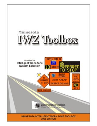
  • 1. MINNESOTA INTELLIGENT WORK ZONE TOOLBOX 2008 EDITION Guideline for Intelligent Work Zone System Selection 25 MI AHEAD EXPECT DELAYS ROAD WORK BE PREPARED TO STOP Minnesota Written, compiled and illustrated by the Minnesota Department of Transportation Office of Traffic, Safety, and Operations
  • 2. this page is intentially left blank
  • 3. 2008 Edition IWZ TOOLBOX page 1IWZ SYSTEM INTRODUCTION Introduction: The IWZ Toolbox has been prepared as a guideline for selecting an appropriate Intelligent Work Zone (IWZ) System for existing work zone traffic issues and to mitigate anticipated issues on scheduled projects. The IWZ System descriptions contained in this toolbox are intended as brainstorming material and should lead to practical solutions to a project's unique problems. The examples are purposely left void of many dimensions, except where particular distances are highly recommended, and engineering judgement is required to customize the system to a project. IWZ Systems may be sorted into 3 category types based upon detectable stimuli: "Traffic", "Vehicle", and "Environmental". The 3 categories are shown below with their typically associated systems: The real-time data collected for any of these systems may be combined, averaged, analyzed for trends, and utilized for several informational uses. For example, data collected for 'Stopped Traffic Warnings' may be to control a 'Dynamic Merge' system or to calculate "Travel Time' through a corridor. Traffic Responsive Systems collect and respond to average traffic characteristics such as speed an volume of a group of vehicles and the systems react to trends of increasing/decreasing values. The combination of these basic systems form the basis for Route Management Systems (or Traveler Information Systems) by analyzing and reporting information in various ways. These applications may include: ! Travel Time Information (Trip Time or Estimated Delay) ! Speed Advisory Information ! Congestion Advisory ! Stopped Traffic Advisory ! Dynamic Merge (Late or Early) ! Traffic Responsive Temporary Signals ! Temporary Ramp Metering Vehicle Responsive Systems collect and respond to individual vehicle characteristics such as speed, dimensions, and location. When adverse conditions are detected by these systems, motorist need immediate warnings for quick response. These applications may include: ! Excessive Speed Warning (including Dynamic Speed Display Signs) ! Over Dimension Warning ! Work Space / Haul Road Intrusion Warning ! Construction Vehicle Warnings Environmentally Responsive Systems collect and respond to changing non-traffic conditions of weather, roadway or working characteristics such as visibility conditions or roadway surface conditions and hazards. These applications may include: ! Hazardous Condition Warnings (Flooding, Ice, Fog, Smoke, Dust, etc.) Temporary Traffic Control Devices may be equipped with advanced communication and/or remote control capabilities which that do not react "intelligently" to detectable field data, but the devices provide safer working conditions or improve incident response. Although these devices may not be "Intelligent", they have been included in the IWZ Toolbox as additional safety tools for consideration when an IWZ System is being deployed. These applications may include: ! Changeable Work Zone Signage (WZ Speed Limit Signs) ! Traffic Surveillance Cameras (removed from Toolbox)
  • 4. 2008 Edition TOOLBOX COMPONENTS Detection Components: The detectors may include: System Analysis Components: analysis algorithms are designed or modified for each application of an! Radar IWZ System to fit the conditions of the project. ! Pneumatic Road Tubes Algorithms can be designed with apparent limitations and strengths, and field testing is necessary to ensure! Light Beams the quality of the data analysis. ! Acoustical ! Ultrasonic Data Management Components: the storage of data ! Magnetic and analysis of the data for various trends, events, etc. may utilize many different database systems.! Piezo-Electric ! Video Dynamic Informational Components: dynamic! RFID components provide information to the motorists and ! Probe Injection Technologies, etc. may include: System Monitoring Components: typical ! 511 Systems (internet & phone/cell phone), redundancies should be built into most systems (based ! Changeable message signs (CMS) in dynamicupon risk assessment for the system failure) and the mode,various types of quality control testing or system monitoring may be utilized. ! Static signs with dynamic features, System Communication Components: the typical ! Remotely activated traffic control devices, forms of transmitting data, some of these may include: ! Audible or visual alarms, ! Cell Phones ! Real-time highway advisory radio (HAR), ! Internet - Wireless Access Points ! Public media announcements, ! Radio ! CB Radio, etc. ! Hard wired ! Optical, etc. IWZ TOOLBOX page 2 Typical System Components: Each IWZ System in the Toolbox is a collection of standard system components which have been combined to produce a useful real-time system. The individual component functions include the collection of data, verifying the accuracy of the data, transmitting the data, storing and managing the data, analyzing the data, and/or providing the data to the motorist. Supplementing Existing System Components: Mn/DOT, through it’s Regional Transportation Management Center (RTMC) and out-state TOCC’s, has the capability to provide a variety of IWZ Systems for Mn/DOT construction and maintenance projects. However, Mn/DOT’s detection devices, communications networks or traveler information systems may not be adequate for a proposed IWZ System. Discrepancies may be due to construction interrupting permanent installations, or that the existing system components do not extend to the project area. IWZ System components provided by a contractor would supplement the services of the RTMC or TOCC’s, when various devices/services are not currently available and may include any of the component types listed above.
  • 5. ! Changeable Message Sign (CMS): a sign that is capable of displaying more than one message, changeable manually, by remote control, or by automatic control. The device is considered "portable" when trailer mounted. The device may be operated in one of two modes: ! Standard Mode: message is programmed to remain displayed until changed by the operator or via a timer. ! Dynamic Mode: the message is programmed to respond to traffic operating characteristics or roadway conditions. ! Static Sign: a message for the motorist is printed on a standard sign, either regulatory, warning or guide signs. ! Advisory Speed: a recommended speed for vehicles based on the current roadway conditions or operating characteristics. Advisory Speeds are not enforceable. ! Speed Limit: the speed applicable to a section of highway as established by law. ! Travel Time: the estimated amount of drive time from the motorist's current location to an identified location, generally limited to approx 10 miles maximum distance. ! Travel Delay: the estimated amount of extra time the motorist will incur due to traffic conditions in a work zone located downstream. Generally useful for spot locations at a great distance away from the motorist's current location, which provides alternate route possibilities. ! Devices (components): the individual parts or subsystems that makeup a working IWZ System. Examples include: cameras, various detectors, signs, data monitoring or recording equipment, communication systems, TTC devices, and remotely activated alarms, etc. ! IWZ System: An automated system of devices that provides motorists and/or workers real-time information for improved safety and mobility through a work zone. The devices are integrated to monitor traffic operating characteristics or roadway conditions and react with a predetermined response. ! Warrants: conditions which should be satisfied before considering an IWZ system for deployment as part of a project's temporary traffic control plan. ! Benefits: anticipated affects mobility and safety when the system is properly designed and deployed. Mobility and safety measures may be within the work zone or surrounding network, and may include the public, the workers, or the constructability of the project. ! Options: various options may be available for portions of the IWZ Systems. The options should be considered when they achieve satisfactory results with lower levels of 'system complication' and cost. DEFINITIONS FOR USE IN THIS DOCUMENT GENERAL IWZ TOOLBOX NOTES SYMBOLS USED IN IWZ TOOLBOX ILLUSTRATIONS ! Changeable Message Sign (CMS): Roadside location symbol shown on left with an example of two alternating messages shown on right. ! Static Guide Sign: Roadside location symbol shown on left with example message shown on right. ! Static Guide Sign with CMS Characters: Roadside location symbol shown on left with example message shown on right. ! Dynamic Flashing Warning Sign: Roadside location symbol shown on left with example message shown on right. ! Advance Warning Sign: Roadside location symbol shown on left with example message shown on right. ! Non-Intrusive Detection Device: The symbol denotes any type of detection device(s) and the actual location and number of devices will vary from the toolbox illustration. ! Temporary Traffic Control (TTC) Device: The symbols denote standard TTC devices as defined by the MN MUTCD and the Field Manual of TTC Layouts. To highlight the IWZ systems, only a minimal amount of TTC devices have been shown on the toolbox illustrations. Key devices shown may include standard warning signs, Type III barricades, channelizing devices and flashing arrow panels. TOOLBOX SYMBOLS and TERMINOLOGY BE PREPARED TO STOP WHEN FLASHING ROAD WORK AHEAD 5 MI AHEAD EXPECT DELAYS ROAD WORK BE PREPARED tO STOP BE PREPARED tO STOP STOPPED TRAFFIC 1 MILE STOPPED TRAFFIC 1 MILE WORK ZONE VEHICLES ONLY ! Advance warning signs and other standard temporary traffic control devices have not been shown on this figure. Refer to the MN MUTCD including the 2007 Field Manual or the TTC Layout Templates for typical layout examples. ! All IWZ Guide Signs and CMS should be reviewed by the Mn/DOT Office of Traffic, Safety, & Operations for design and message approval. ! Approved CMS messages should be listed in the Special Provisions, and approx CMS locations should shown on the TTC plans. All CMS displays should be blank when messages are not warranted. ! Refer to the Toolbox Definitions Section for graphic symbols and terms. ! Toolbox Illustrations are NOT Drawn to Scale. IWZ TOOLBOX page 3 2008 Edition
  • 6. Note: The IWZ Toolbox Sheets contained within this document are preliminary illustrations and may not accurately represent all the IWZ Systems as typically deployed. The systems may be combined, modified, enhanced or simplified as necessary for a particular project. Please use these toolbox sheets to brainstorm IWZ possibilities, and consider what conditions may be needed to make the application viable. When a system is deployed, we hope to quantify these conditions further, with refined warrants on the system's toolbox sheet. We also wish to quantify benefits derived from the deployments where ever possible in addition to the intuitive benefits that may be reaped from the IWZ systems. IWZ TOOLBOX page 4TOOLBOX INDEX2008 Edition IWZ SYSTEMS LISTED IN THIS PUBLICATION ! Travel Time Information - Trip Time or Estimated Delay ! Speed Advisory Information ! Congestion Advisory ! Stopped Traffic Advisory ! Dynamic Merge - Late or Early ! Traffic Responsive Temporary Signals ! Temporary Ramp Metering ! Excessive Speed Warning - incl. Dynamic Speed Display Signs ! Over Dimension Warning ! Work Space / Haul Road Intrusion Warning ! Construction Vehicle Warnings - Merging, Crossing & Exiting ! Hazardous Condition Warnings - Road Surface or Visibility ! Changeable Work Zone Signage - incl. WZ Speed Limits !
  • 7. Intelligent Work Zone Systems Toolbox WARRANTS BENEFITS OPTIONSLayouts are NOT drawn to scale. NOTES ! Advance warning signs and other standard temporary traffic control devices have not been shown on this figure. Refer to the MN MUTCD including the 2007 Field Manual or the TTC Layout Templates for typical layout examples. ! All IWZ Guide Signs and CMS should be reviewed by the Mn/DOT Office of Traffic, Safety, & Operations for design and message approval. ! Approved CMS messages should be listed in the Special Provisions, and approx CMS locations should shown on the TTC plans. All CMS displays should be blank when messages are not warranted. ! Refer to the Toolbox Definitions Section for graphic symbols and terms. ! The work zone may cause 15 minutes or more of additional travel time. ! The work zone causing the delay is within 10 miles of the CMS location. ! ! The system should inform the drivers what the estimated travel time is between their current location and a specific destination beyond them (up to 10 miles maximum). The system will give drivers information which will allow them to decide whether to change routes, provide them opportunity to notify others of their estimated arrival time, and generally provide drivers sufficient information to calm tempers. TRAVEL TIME INFORMATION TRAFFIC RESPONSIVE ! The CMS may be replaced with static warning signs equipped with two (2) CMS characters in dynamic mode. The characters would display the real-time travel time in the work zone downstream. ! Consideration should be given to posting an alternate route and travel time for additional driver information. ! The CMS may be supplemented with other informational devices such as Highway Advisory Radio (HAR). WORK ZONE CAUSING DELAY TIME TO HWY CC 35 MIN TIME TO HWY CC 35 MIN Distance from sign to the destination is limited to approx. 10 miles for accuracy HWY CC HWY BB OR Optional Signing Consideration should be given to posting an alternate route and travel time for additional driver information. Intelligent Work Zone Systems Toolbox Last Revision Date: WARRANTS BENEFITS OPTIONSLayouts are NOT drawn to scale. 04-29-08 NOTES ! Advance warning signs and other standard temporary traffic control devices have not been shown on this figure. Refer to the MN MUTCD including the 2007 Field Manual or the TTC Layout Templates for typical layout examples. ! All IWZ Guide Signs and CMS should be reviewed by the Mn/DOT Office of Traffic, Safety, & Operations for design and message approval. ! Approved CMS messages should be listed in the Special Provisions, and approx CMS locations should shown on the TTC plans. All CMS displays should be blank when messages are not warranted. ! Refer to the Toolbox Definitions Section for graphic symbols and terms. ESTIMATED TRIP TIME
  • 8. Intelligent Work Zone Systems Toolbox WARRANTS BENEFITS OPTIONSLayouts are NOT drawn to scale. NOTES ! Advance warning signs and other standard temporary traffic control devices have not been shown on this figure. Refer to the MN MUTCD including the 2007 Field Manual or the TTC Layout Templates for typical layout examples. ! All IWZ Guide Signs and CMS should be reviewed by the Mn/DOT Office of Traffic, Safety, & Operations for design and message approval. ! Approved CMS messages should be listed in the Special Provisions, and approx CMS locations should shown on the TTC plans. All CMS displays should be blank when messages are not warranted. ! Refer to the Toolbox Definitions Section for graphic symbols and terms. ! The work zone may cause 15 minutes or more of additional travel time. ! The work zone causing the delay is located more than 10 miles beyond the CMS location (preferably 25 to 50 miles or more, such that multiple alternate routes are available). ! ! System should inform the drivers what the estimated delay time is at an approximate location along the roadway downstream. The delay is calculated based upon queue speeds vs. normal travel speeds. The system will give drivers information which will allow them to decide whether to change routes, provide them opportunity to notify others of their estimated arrival time, and generally provides drivers sufficient information to calm tempers when they arrive at the cause of the delay. TRAVEL DELAY INFORMATION ! The CMS may be replaced with static warning signs equipped with two (2) CMS characters in dynamic mode. The characters would display the real-time travel delay in the work zone downstream. ! ! Consideration should be given to posting an alternate route and travel time for additional driver information. The system may be converted to a Travel Time system within 10 miles of the destination location (such as Hwy CC in this example). ! The CMS may be supplemented with other informational devices such as Highway Advisory Radio (HAR). WORK ZONE CAUSING DELAY sign located approx 800 feet before CMS sign located approx 800 feet before CMS EXPECT 25 MIN DELAY EXPECT 25 MIN DELAY ROAD WORK AT HWY CC ROAD WORK AT HWY CC EXPECT 25 MIN DELAY EXPECT 25 MIN DELAY ROAD WORK AT HWY CC ROAD WORK AT HWY CC Non-Intrusive Detection spaced along the route as needed for proper system operations. Detection should extend beyond limits of work zone congestion. Multiple CMS locations may be deployed depending upon availability of alternate routes. Alternate Route Exit HWY CC HWY BB Intelligent Work Zone Systems Toolbox Last Revision Date: WARRANTS BENEFITS OPTIONSLayouts are NOT drawn to scale. 04-29-08 NOTES ! Advance warning signs and other standard temporary traffic control devices have not been shown on this figure. Refer to the MN MUTCD including the 2007 Field Manual or the TTC Layout Templates for typical layout examples. ! All IWZ Guide Signs and CMS should be reviewed by the Mn/DOT Office of Traffic, Safety, & Operations for design and message approval. ! Approved CMS messages should be listed in the Special Provisions, and approx CMS locations should shown on the TTC plans. All CMS displays should be blank when messages are not warranted. ! Refer to the Toolbox Definitions Section for graphic symbols and terms. TRAFFIC RESPONSIVE ESTIMATED DELAY TIME
  • 9. Intelligent Work Zone Systems Toolbox WARRANTS BENEFITS OPTIONSLayouts are NOT drawn to scale. NOTES ! Advance warning signs and other standard temporary traffic control devices have not been shown on this figure. Refer to the MN MUTCD including the 2007 Field Manual or the TTC Layout Templates for typical layout examples. ! All IWZ Guide Signs and CMS should be reviewed by the Mn/DOT Office of Traffic, Safety, & Operations for design and message approval. ! Approved CMS messages should be listed in the Special Provisions, and approx CMS locations should shown on the TTC plans. All CMS displays should be blank when messages are not warranted. ! Refer to the Toolbox Definitions Section for graphic symbols and terms. ! The work zone will cause additional travel time. ! The work zone queue is estimated to slow traffic at least 20 mph below the posted speed limit. ! ! ! The system should advise drivers of an appropriate vehicle speed to allow them to travel through the work zone with minimal braking. The system will smooth the transition between faster and slower moving traffic. The system should provide an increase in capacity of the roadway through the work zone area. SPEED ADVISORY INFORMATION ! The CMS may be replaced with static warning signs equipped with two (2) CMS characters in dynamic mode. The characters would display the real-time average speed in the work zone downstream. OPTIONAL DESIGN: combination of static sign and digital number display WORK ZONE CAUSING DELAY QUEUE OF SLOWED TRAFFIC 30 MPH TRAFFIC AHEAD 30 MPH TRAFFIC AHEAD WATCH FOR SLOW TRAFFIC WATCH FOR SLOW TRAFFIC Non-Intrusive Detection spaced along the route as needed for proper system operations. Detection should extend beyond limits of work zone congestion. The CMS should be located 2 - 3 miles before the slow traffic queue. The displayed speed is the average speed detected entering the work zone location. Based upon this information, the motorist may adjust speed to anticipate the slower traffic. Intelligent Work Zone Systems Toolbox Last Revision Date: WARRANTS BENEFITS OPTIONSLayouts are NOT drawn to scale. 04-29-08 NOTES ! Advance warning signs and other standard temporary traffic control devices have not been shown on this figure. Refer to the MN MUTCD including the 2007 Field Manual or the TTC Layout Templates for typical layout examples. ! All IWZ Guide Signs and CMS should be reviewed by the Mn/DOT Office of Traffic, Safety, & Operations for design and message approval. ! Approved CMS messages should be listed in the Special Provisions, and approx CMS locations should shown on the TTC plans. All CMS displays should be blank when messages are not warranted. ! Refer to the Toolbox Definitions Section for graphic symbols and terms. TRAFFIC RESPONSIVE
  • 10. Intelligent Work Zone Systems Toolbox Last Revision Date: WARRANTS NOTES BENEFITS OPTIONS Non-Intrusive Detection spaced along the route as needed for proper system operations OR OR Optional Signage WORK ZONE CAUSING DELAY Example messages: When an alternate route exists prior to the queue. Example messages: When no alternate routes are available prior to the queue. ! When queues are estimated to never extend to the CMS location, the CMS may be replaced with a static warning sign equipped with two dynamic CMS characters for mileage. When no queues are detected, the mileage display would correspond with the accompanying guide sign for "Road Work XX Mi Ahead". CONGESTION ADVISORY ! When traffic queue lengths are reasonably predictable, warning motorists of stopped / slowed traffic may be accomplished with the use of typical TTC warning signs placed prior to the anticipated beginning of queue. ! The system may be combined with "Dynamic Merge", "Stopped Traffic Warning" and "Travel Time and/or Delay" systems. Layouts are NOT drawn to scale. BE PREPARED tO STOP BE PREPARED tO STOP STOPPED TRAFFIC 1 MILE STOPPED TRAFFIC 1 MILE 5 MI AHEAD EXPECT DELAYS ROAD WORK BE PREPARED tO STOP BE PREPARED tO STOP STOPPED TRAFFIC 11 MILES STOPPED TRAFFIC 11 MILES CONSIDER other ROUTES CONSIDER other ROUTES 15 MI AHEAD EXPECT DELAYS ROAD WORK STOPPED TRAFFIC 11 MILES STOPPED TRAFFIC 11 MILES 25 MI AHEAD EXPECT DELAYS ROAD WORK CONSIDER other ROUTES CONSIDER other ROUTES STOPPED TRAFFIC 21 MILES STOPPED TRAFFIC 21 MILES 10-01-07 ! Queue lengths are estimated to vary greatly, day-by-day and hour-by-hour such that a suitable location for the TTC advance warning signage can not be predicted. Note: signs placed more than a mile ahead of confirmation are typically forgotten by the motorist. ! Queue lengths may encroach upstream beyond a motorist's reasonable expectations for stopped traffic and there is probability that the geometrics (terrain) may cause poor visibility of end of traffic queues, causing short reaction times and panic stopping. ! The queue is estimated to stop downstream of the last CMS in the system. ! The system should ! alert drivers of an upcoming traffic slow-down or stopped traffic, providing time to determine possible route alternates, and to be prepared to stop safely. Traffic may divert to alternate routes. ! Advance warning signs and other standard temporary traffic control devices have not been shown on this figure. Refer to the MN MUTCD including the 2007 Field Manual or the TTC Layout Templates for typical layout examples. ! All IWZ Guide Signs and CMS should be reviewed by the Mn/DOT Office of Traffic, Safety, & Operations for design and message approval. ! Approved CMS messages should be listed in the Special Provisions, and approx CMS locations should shown on the TTC plans. All CMS displays should be blank when messages are not warranted. ! Refer to the Toolbox Definitions Section for graphic symbols and terms. 800 ft. apart 800 ft. apart 800 ft. apart STO P P ED TRAFFI C M I LES AH EAD 2 1 STO P P ED TRAFFI C M I LES AH EAD 2 1 OPERATIONAL NOTES: ! When no queue is detected, all the CMS should be blank unless used for another IWZ system. ! When the queue approaches within one mile of any CMS, the CMS should operate as a "Stopped Traffic Advisory" device. ! When the queue extends beyond any CMS location, the CMS should be blank, or it may be utilized for another IWZ system such as DLM. Queue length for this example (4 miles) TRAFFIC RESPONSIVE
  • 11. Intelligent Work Zone Systems Toolbox Last Revision Date: WARRANTS NOTES BENEFITS OPTIONS ! The CMS may be replaced with an appropriate warning sign equipped with dynamically automated flashing lights as shown below. ! The static signs are spaced incrementally and the individual flashers are activated in response to queued traffic when the queue is detected within one mile of the sign location. ! When traffic queue lengths are reasonably predictable, warning motorists of stopped / slowed traffic may be accomplished with the use of typical TTC warning signs placed prior to the anticipated beginning of queue. ! The system may be combined with "Dynamic Merge" and "Stopped Traffic Advisory" systems STOPPED TRAFFIC ADVISORY Layouts are NOT drawn to scale. B E P R E P A R E D T O S T O P WHEN FLASHING ! Queue lengths are estimated to vary greatly, day-by-day and hour-by-hour such that a suitable location for the TTC advance warning signage can not be predicted. Note: signs placed more than a mile ahead of confirmation are typically forgotten by the motorist. ! Queue lengths may encroach upstream beyond a motorist's reasonable expectations for stopped traffic and there is probability that the geometrics (terrain) may cause poor visibility of end of traffic queues, causing short reaction times and panic stopping. ! Queues initiated on crossroads are estimated to cause traffic conflicts and/or delays on the mainline road, such as backups beyond the length of ramps, through or around turns in intersections, or other hazardous congestion situations. ! The system should ! ! alert drivers of an upcoming traffic slow-down or stopped traffic, providing time to determine possible route alternates, and to be prepared to stop safely. It is anticipated that the system will reduce rear-end crashes. Traffic may divert to alternate routes. ! Advance warning signs and other standard temporary traffic control devices have not been shown on this figure. Refer to the MN MUTCD including the 2007 Field Manual or the TTC Layout Templates for typical layout examples. ! All IWZ Guide Signs and CMS should be reviewed by the Mn/DOT Office of Traffic, Safety, & Operations for design and message approval. ! Approved CMS messages should be listed in the Special Provisions, and approx CMS locations should shown on the TTC plans. All CMS displays should be blank when messages are not warranted. ! Refer to the Toolbox Definitions Section for graphic symbols and terms. Non-Intrusive Detection spaced along the route as needed for proper system operations WORK ZONE CAUSING DELAY BE PREPARED tO STOP BE PREPARED tO STOP STOPPED TRAFFIC AHEAD STOPPED TRAFFIC AHEAD Optional Signing OR BE PREPARED tO STOP BE PREPARED tO STOP STOPPED TRAFFIC AHEAD STOPPED TRAFFIC AHEAD Optional Signing OR BE PREPARED TO STOP WHEN FLASHING BE PREPARED TO STOP WHEN FLASHING BE PREPARED TO STOP WHEN FLASHING BE PREPARED tO STOP BE PREPARED tO STOP STOPPED TRAFFIC AHEAD STOPPED TRAFFIC AHEAD Optional Signing OR The signs are spaced incrementally and are activated in response to queued traffic when the queue is detected within one mile of the sign location. As the queue extends beyond a CMS location, the sign should switch to only the "Prepare to Stop" message. When no queue is detected, all the CMS should be blank or used for another ITS system. 04-29-08 TRAFFIC RESPONSIVE OPTIONAL SIGN DESIGN
  • 12. Intelligent Work Zone Systems Toolbox Last Revision Date: ! Two lanes of must merge into one direction will be closed to traffic and traffic must merge. ! Although queues may develop at low volumes for many reasons, typically, the volume must exceed 1500 vehicles/hour to sustain a queue that was caused by merging lanes. ! Estimated queue lengths may encroach beyond an upstream intersection or interchange operations. ! The speeds and lane occupancy volumes are anticipated to vary unpredictably causing the motorist to have trouble identifying the best lane usage practice, such as using both lanes versus moving into the continuous thru-lane. ! The system should ! ! ! alert drivers of an upcoming traffic slow-down or stopped traffic, and inform them to use both lanes until the designated merge point. It is anticipated that the system will reduce the length of the upstream queue by 40%, which may reduce conflicts at nearby intersections. By utilizing both traffic lanes, the differential speed between lanes is greatly reduced since both lanes travel at approx the same speed. Motorists are given positive directions on lane usage and merging which clears misunderstandings between drivers and reduces road rage. WARRANTS BENEFITS OPTIONS DYNAMIC LATE MERGE ! ! ! ! ! When traffic queue lengths are reasonably low and predictable, instructing motorists of proper lane usage may be accomplished with the use of typical TTC warning signs placed prior to the anticipated beginning of queue. The dynamic system may be combined with Congestion Warning and Travel Time and/or Delay Systems. When the speeds and lane occupancy volumes are anticipated to increase very predictably and hold at that a high level, the motorist should have little trouble identifying when the traffic is congesting and begin to follow the posted merging procedure, such as using both lanes. Only clear directions on proper actions are needed by the motorist. Two options: The directions may be supplied on static guide signs posted beyond the anticipated queue length and repeated within the queue area. An example series of Static Signs is shown below: When the congestion time is highly predictable, the directions may be posted on CMS as shown in the illustration, and activated by timers, rather that traffic conditions. Layouts are NOT drawn to scale. USE BOTH LANES USE BOTH LANES STOPPED TRAFFIC AHEAD STOPPED TRAFFIC AHEAD USE BOTH LANES USE BOTH LANES MERGE AHEAD MERGE AHEAD TAKE TURNS TAKE TURNS MERGE HERE MERGE HERE MERGE TAPER BUFFER Non-Intrusive Detection spaced along the route as needed for proper system operations CMS located beyond the estimated maximum queue length CMS located beyond the estimated queue length at the time when system activation will occur CMS located at point of merge The first advance warning sign should be located before the estimated queue beginning ROAD WO R K 15 M IL ES AH EAD EXP ECT LO N G BACKU PS O N WEEKEN DS D U R I N G BACKU PS U S E BOTH LAN ES TAKE TU R N S AT M ERG E NOTES ! Advance warning signs and other standard temporary traffic control devices have not been shown on this figure. Refer to the MN MUTCD including the 2007 Field Manual or the TTC Layout Templates for typical layout examples. ! All IWZ Guide Signs and CMS should be reviewed by the Mn/DOT Office of Traffic, Safety, & Operations for design and message approval. ! Approved CMS messages should be listed in the Special Provisions, and approx CMS locations should shown on the TTC plans. All CMS displays should be blank when messages are not warranted. ! Refer to the Toolbox Definitions Section for graphic symbols and terms. 04-29-08 TRAFFIC RESPONSIVE
  • 13. Intelligent Work Zone Systems Toolbox Last Revision Date: WARRANTS BENEFITS OPTIONSLayouts are NOT drawn to scale. NOTES ! Advance warning signs and other standard temporary traffic control devices have not been shown on this figure. Refer to the MN MUTCD including the 2007 Field Manual or the TTC Layout Templates for typical layout examples. ! All IWZ Guide Signs and CMS should be reviewed by the Mn/DOT Office of Traffic, Safety, & Operations for design and message approval. ! Approved CMS messages should be listed in the Special Provisions, and approx CMS locations should shown on the TTC plans. All CMS displays should be blank when messages are not warranted. ! Refer to the Toolbox Definitions Section for graphic symbols and terms. ! ! SHEET UNDER DEVELOPMENT DYNAMIC EARLY MERGE 00-00-00 TRAFFIC RESPONSIVE MERGE TAPER Non-Intrusive Detection spaced along the route as needed for proper system operations CMS located beyond the estimated queue length at the time when system activation will occur Always Flashing at this Location (within one mile) Spaced at ¼ - ½ mile increments for estimated length of queue The first advance warning sign should be located before the estimated queue beginning MERGE RIGHT MERGE RIGHT FORM ONE LANE RIGHT LEFT LANE CLOSED 1 MILE
  • 14. Intelligent Work Zone Systems Toolbox Last Revision Date: WARRANTS BENEFITS OPTIONSLayouts are NOT drawn to scale. 10-01-07 NOTES ! Advance warning signs and other standard temporary traffic control devices have not been shown on this figure. Refer to the MN MUTCD including the 2007 Field Manual or the TTC Layout Templates for typical layout examples. ! All IWZ Guide Signs and CMS should be reviewed by the Mn/DOT Office of Traffic, Safety, & Operations for design and message approval. ! Approved CMS messages should be listed in the Special Provisions, and approx CMS locations should shown on the TTC plans. All CMS displays should be blank when messages are not warranted. ! Refer to the Toolbox Definitions Section for graphic symbols and terms. ! ! TRAFFIC RESPONSIVE TEMPORARY SIGNALS SHEET UNDER DEVELOPMENT TRAFFIC RESPONSIVE
  • 15. Intelligent Work Zone Systems Toolbox Last Revision Date: WARRANTS BENEFITS OPTIONSLayouts are NOT drawn to scale. 05-01-08 NOTES ! Advance warning signs and other standard temporary traffic control devices have not been shown on this figure. Refer to the MN MUTCD including the 2007 Field Manual or the TTC Layout Templates for typical layout examples. ! All IWZ Guide Signs and CMS should be reviewed by the Mn/DOT Office of Traffic, Safety, & Operations for design and message approval. ! Approved CMS messages should be listed in the Special Provisions, and approx CMS locations should shown on the TTC plans. All CMS displays should be blank when messages are not warranted. ! Refer to the Toolbox Definitions Section for graphic symbols and terms. ! ! TEMPORARY RAMP METERING SHEET UNDER DEVELOPMENT TRAFFIC RESPONSIVE Traffic forms two lanes, allowing the total queue length to be reduced. Advance notification of change in traffic control may be used. Temporary pedestal mounted traffic signals. Green alternates between the two signal heads, requiring the two lanes to take turns. Non-Intrusive Detection spaced along the route as needed for proper system operations. Detection measures speed/capacity of traffic and determines the cycle length for the ramp meters. RAMP METERING BEGINS JUNE 10
  • 16. Intelligent Work Zone Systems Toolbox Last Revision Date: WARRANTS BENEFITS OPTIONSLayouts are NOT drawn to scale. NOTES ! Advance warning signs and other standard temporary traffic control devices have not been shown on this figure. Refer to the MN MUTCD including the 2007 Field Manual or the TTC Layout Templates for typical layout examples. ! All IWZ Guide Signs and CMS should be reviewed by the Mn/DOT Office of Traffic, Safety, & Operations for design and message approval. ! Approved CMS messages should be listed in the Special Provisions, and approx CMS locations should shown on the TTC plans. All CMS displays should be blank when messages are not warranted. ! Refer to the Toolbox Definitions Section for graphic symbols and terms. EXSESSIVE SPEED WARNING ! Traffic must reduce speed to safety negotiate a hazardous condition such as a temporary unusually tight curve, or a rough road surface. ! Buffer spaces and/or clear-zones should be analyzed for possible intrusions by vehicles unable to sufficiently slow down in time. ! ! System should alert a driver that they have inadvertently entered a portion of the work zone at a speed substantially above the advisory speed limit. The system provides sufficient time to slow down for the hazardous condition. Non-Intrusive Detection placed along the roadway as needed for proper system operations. REDUCE SPEED NOW REDUCE SPEED NOW EXCEEDED SPEED LIMIT EXCEEDED SPEED LIMIT 45 45 Example shows a reduced advisory speed limit due to sharp curve with either a substandard clear zone or inadequate buffer zone for errant vehicles. 04-29-08 VEHICLE RESPONSIVE
  • 17. A XX MPH The work crew (or poor road condition) should be visible to the driver from the point of viewing the Advisory Speed Plaque and DSD sign display. Preliminary studies show 500' is the optimum distance for speed reduction, therefore, it's advised to maintain that distance as much as practical. As workers move within the work zone, the DSD location should be re-positioned such that it remains within 500 feet (min) and 2500 feet (max) of the worker location. The distances may be adjusted following further studies of the DSD sign usage in work zones. WORKER LOCATION 500' min. OPTIONAL: warning sign with speed advisory (see note below) When the DSD sign is utilizing an Advisory Speed Limit, a warning sign shall be displayed adjacent to the DSD sign location. The Advisory Speed Plaque may be attached to the warning sign, or mounted on the DSD sign device. The "YOUR SPEED" sign on the DSD device shall be black on flourescent orange. When utilizing the DSD sign with either a regulatory speed limit or work zone speed limit, the "YOUR SPEED" sign on the DSD device shall be black on white. The DSD sign shall be either placed adjacent to the posted speed limit sign, or the appropriate speed limit sign shall be mounted to the DSD device. 08/14/09 NOTE: The changes to this layout (in ) are recommendations that are currently being studied for optimum sign usage and location. This preliminary layout should be followed until a final report made. RED When used, the optional advance warning sign with speed advisory should be placed a minimum distance 'A' ahead of the workers and a minimum 250 feet ahead of the DSD device location. The distance 'A' is the Advance Warning Sign Spacing based upon the Posted Speed Limit and is found in the Field Manual (Part 6K of the MnMUTCD).
  • 18. Intelligent Work Zone Systems Toolbox Last Revision Date: WARRANTS BENEFITS OPTIONSLayouts are NOT drawn to scale. NOTES ! Advance warning signs and other standard temporary traffic control devices have not been shown on this figure. Refer to the MN MUTCD including the 2007 Field Manual or the TTC Layout Templates for typical layout examples. ! All IWZ Guide Signs and CMS should be reviewed by the Mn/DOT Office of Traffic, Safety, & Operations for design and message approval. ! Approved CMS messages should be listed in the Special Provisions, and approx CMS locations should shown on the TTC plans. All CMS displays should be blank when messages are not warranted. ! Refer to the Toolbox Definitions Section for graphic symbols and terms. ! Construction causes temporary minimal clearance (or less than minimum) for large vehicles using the roadway, or ! A minimal clearance condition exists within a work zone and construction vehicles must be warned of the condition. ! ! ! The system should alert a driver that their vehicle is over- dimension and they are required to use an escape route. The system should alert drivers of their route mistake and provide sufficient time to conduct the escape maneuver. The second portion of the system warns a driver to stop if he failed to use the designated escape route. OVER DIMENSION WARNING Non-Intrusive Detection placed along the roadway as needed to measure for over-dimension vehicles. Non-Intrusive Detection placed to determine whether an over-dimension vehicle missed the exit. ESCAPE ROUTE EXIT POINT OF CLEARANCE RESTRICTION (an example may include height or width reductions due to bridge repairs or painting) ROOM TO STOP AND PULL OVER BEFORE RESTRICTION RETURN ROUTE (Entrance Ramp) LOW BRIDGE AHEAD TRUCKS OVER 13' 5" MUST USE BYPASS EXIT YOU MUST EXIT NOW YOU MUST EXIT NOW OVER HEIGHT DETECTED OVER HEIGHT DETECTED STOP THE VEHICLE NOW STOP THE VEHICLE NOW LOW BRIDGE AHEAD LOW BRIDGE AHEAD OR Optional Signing A siren or horn alarm may be included to warn workers of a vehicle intrusion A siren or horn alarm may be included to warn the vehicle driver 04-29-08 VEHICLE RESPONSIVE
  • 19. Intelligent Work Zone Systems Toolbox Last Revision Date: WARRANTS BENEFITS OPTIONSLayouts are NOT drawn to scale. NOTES ! Advance warning signs and other standard temporary traffic control devices have not been shown on this figure. Refer to the MN MUTCD including the 2007 Field Manual or the TTC Layout Templates for typical layout examples. ! All IWZ Guide Signs and CMS should be reviewed by the Mn/DOT Office of Traffic, Safety, & Operations for design and message approval. ! Approved CMS messages should be listed in the Special Provisions, and approx CMS locations should shown on the TTC plans. All CMS displays should be blank when messages are not warranted. ! Refer to the Toolbox Definitions Section for graphic symbols and terms. WORK SPACE INTRUSION: ! Vehicles inadvertently fail to follow standard flagging operations. HAUL ROAD INTRUSION: ! Vehicles inadvertently follow a truck off the roadway. Reasons for following may vary: ! High roadway volume causing tailgating ! Truck exit is difficult to identify ! ! ! The systems should alert a driver that they have inadvertently followed a construction truck into the construction zone or intruded into a work space. A work space intrusion system should alert a workers that a vehicle has intruded into the work zone. The systems should provide sufficient time for the driver to react appropriately, such as utilize an escape route back to the roadway traffic. WORK INTRUSION WARNING HAUL ROAD INTRUSION WORK SPACE INTRUSION DONOT FOLLOW TRuCKS DONOT FOLLOW TRuCKS RETURN BACKTO ROADWAY RETURN BACKTO ROADWAY STOPNOW STOPNOW STOPNOW STOPNOW HAUL ROAD Non-Intrusive Detection placed near truck exit lane as needed for proper system operations. The detection may include radio control devices operated by the truck drivers. ESCAPE LANE TRUCKSEXITING ONRIGHT DONOT FOLLOWTRUCKS WORKZONE VEHICLES ONLY WORKZONE VEHICLES ONLY DECELERATION AREA Deceleration distance should be based upon reaction time and braking distances. (currently not required in a work zone layout) A siren or horn alarm may be included to warn workers of a vehicle intrusion. Detection may include radio control devices operated by the flagger. BUFFER WORK SPACE CMS may be blank or used for another ITS function until needed. CMS may be blank or used for another ITS function until needed. 04-29-08 VEHICLE RESPONSIVE Display/alarms activated by truck driver
  • 20. Intelligent Work Zone Systems Toolbox Last Revision Date: WARRANTS BENEFITS OPTIONSLayouts are NOT drawn to scale. NOTES ! Advance warning signs and other standard temporary traffic control devices have not been shown on this figure. Refer to the MN MUTCD including the 2007 Field Manual or the TTC Layout Templates for typical layout examples. ! All IWZ Guide Signs and CMS should be reviewed by the Mn/DOT Office of Traffic, Safety, & Operations for design and message approval. ! Approved CMS messages should be listed in the Special Provisions, and approx CMS locations should shown on the TTC plans. All CMS displays should be blank when messages are not warranted. ! Refer to the Toolbox Definitions Section for graphic symbols and terms. ! The trucks must utilize the mainline roadway to accelerate. ! A truck merge lane can not be provided on the project. ! The haul road entrance is visibly obscured to drivers. ! The ADT on the roadway is above the level where truck drivers can easily find a gap in traffic and accelerate within the traffic lane without causing traffic to suddenly adjust speed or change lanes. ! A variation of this system may be used to detect work vehicles in the vicinity which may create a traffic hazard. The example shown below warned the motorists when snow plows were clearing the roadway in a restricted section. The signs were activated by radio communications from the plow trucks. ! ! ! The system should alert drivers of a slowly accelerating truck entering the faster moving traffic lane. The system should provide sufficient time for drivers to react appropriately, such as slowing down or changing lanes. TRUCKS MERGING TRAFFIC WARNING Scenario C. No Acceleration Lane TRUCK HAUL ROAD Non-Intrusive Detection placed along the roadway as needed for proper system operations. The detection may include radio control devices operated by the truck drivers. Haul Road Haul Road Dedicated Lane Acceleration Lane Scenario A. Scenario B. Typically, IWZ Systems are not needed for construction traffic is this scenario. Although this scenario may operate efficiently without an IWZ system installed, higher traffic / truck volumes or a short accelleration lane would warrant the IWZ system. BE PREPARED TO STOP BE PREPARED TO STOP TRUCKS MERGEING 1000 FT TRUCKS MERGEING 1000 FT BE PREPARED TO STOP BE PREPARED TO STOP TRUCKS MERGEING 1000 FT TRUCKS MERGEING 1000 FT TRUCKS MERGEING TRAFFIC WHEN FLASHING Optional Signing OR 04-29-08 VEHICLE RESPONSIVE
  • 21. Intelligent Work Zone Systems Toolbox Last Revision Date: WARRANTS BENEFITS OPTIONSLayouts are NOT drawn to scale. NOTES ! Advance warning signs and other standard temporary traffic control devices have not been shown on this figure. Refer to the MN MUTCD including the 2007 Field Manual or the TTC Layout Templates for typical layout examples. ! All IWZ Guide Signs and CMS should be reviewed by the Mn/DOT Office of Traffic, Safety, & Operations for design and message approval. ! Approved CMS messages should be listed in the Special Provisions, and approx CMS locations should shown on the TTC plans. All CMS displays should be blank when messages are not warranted. ! Refer to the Toolbox Definitions Section for graphic symbols and terms. ! The ADT on the roadway is above the level where truck drivers can easily recognize a gap in traffic and safety cross without causing conflicts with traffic. ! TRUCKS CROSSING TRAFFIC WARNING Scenerio F. Cross 2-Lane 2-Way ! When higher ADT conditions exist such that trucks are not able to find a gap in traffic, then additional traffic control systems, such as flaggers, stop signs or temporary signals, should be utilized to slow or stop traffic. TRUCK HAUL ROAD Non-Intrusive Detection placed along the haul road as needed for proper system operations. The detection may include radio control devices operated by the truck drivers. The crossing could be deployed with either the trucks yielding or the traffic yielding, depending upon the volume of each. Haul Road Haul Road Cross Single Lane Cross Double Lane Scenerio D. Scenerio E. ! ! ! The system should alert drivers of a slowly accelerating truck crossing the traffic lane. The system should provide drivers sufficient time to react appropriately, such as slowing down. ! The CMS may be replaced with an appropriate warning sign equipped with dynamically automated flashing lights as shown below and on scenario D. TRUCKS CROSSING TRAFFIC WHEN FLASHING be prepared to stop be prepared to stop TRUCKS CROSSING 1000 ft TRUCKS CROSSING 1000 ft be prepared to stop be prepared to stop TRUCKS CROSSING 1000 ft TRUCKS CROSSING 1000 ft be prepared to stop be prepared to stop TRUCKS CROSSING 1000 ft TRUCKS CROSSING 1000 ft 04-29-08 VEHICLE RESPONSIVE
  • 22. Intelligent Work Zone Systems Toolbox Last Revision Date: WARRANTS BENEFITS OPTIONSLayouts are NOT drawn to scale. NOTES ! Advance warning signs and other standard temporary traffic control devices have not been shown on this figure. Refer to the MN MUTCD including the 2007 Field Manual or the TTC Layout Templates for typical layout examples. ! All IWZ Guide Signs and CMS should be reviewed by the Mn/DOT Office of Traffic, Safety, & Operations for design and message approval. ! Approved CMS messages should be listed in the Special Provisions, and approx CMS locations should shown on the TTC plans. All CMS displays should be blank when messages are not warranted. ! Refer to the Toolbox Definitions Section for graphic symbols and terms. ! The trucks must utilize the mainline roadway to de- accelerate, and ! The roadway volume is above the level where the traffic must suddenly adjust speed or change lanes. ! ! The system should alert drivers of a decelerating truck exiting the faster moving traffic lane. The system should provide drivers sufficient time to react appropriately, such as slow down or change lanes if possible. TRUCKS EXITING TRAFFIC WARNING Haul Road Haul Road De-acceleration Lane Scenerio G. Scenerio H. Scenerio I. No De-acceleration Lane DO NOT FOLLOW TRUCKS DO NOT FOLLOW TRUCKS TRUCKS EXITING 2000 ft TRUCKS EXITING 2000 ft Non-Intrusive Detection placed along the roadway as needed for proper system operations. The detection may include radio control devices operated by the truck drivers. WORK ZONE VEHICLES ONLY WORK ZONE VEHICLES ONLY Typically, IWZ Systems are not needed for construction traffic is this scenario. Haul Road Dedicated Lane WORK ZONE VEHICLES ONLY Typically, IWZ Systems are not needed for construction traffic is this scenario. 04-29-08 VEHICLE RESPONSIVE
  • 23. Intelligent Work Zone Systems Toolbox Last Revision Date: WARRANTS BENEFITS OPTIONSLayouts are NOT drawn to scale. 10-01-07 NOTES ! Advance warning signs and other standard temporary traffic control devices have not been shown on this figure. Refer to the MN MUTCD including the 2007 Field Manual or the TTC Layout Templates for typical layout examples. ! All IWZ Guide Signs and CMS should be reviewed by the Mn/DOT Office of Traffic, Safety, & Operations for design and message approval. ! Approved CMS messages should be listed in the Special Provisions, and approx CMS locations should shown on the TTC plans. All CMS displays should be blank when messages are not warranted. ! Refer to the Toolbox Definitions Section for graphic symbols and terms. ! The system should be considered for deployment as part of a project’s temporary traffic control plan when a temporary situation may cause a hazardous driving condition such as: • Flash flooding • Visibility (fog, smoke) • Slippery or rough conditions • Hazards on roadway (falling rock, debris) ! ! The system should alert traffic of a hazardous condition on the roadway ahead and advise traffic of an appropriate action for the situation which may range from stopping, slowing, or diverting traffic. The system should notify construction staff of the situation such that corrective actions may begin. HAZARDOUS ROADWAY WARNING Non-Intrusive Detection spaced along the route as needed for proper system operations Example: Area prone to Flash Flooding due to poor roadway drainage during a construction stage. USE ALT ROUTE EXIT NOW USE ALT ROUTE EXIT NOW FLOODED ROADWAY AHEAD FLOODED ROADWAY AHEAD BE PREPARED TO STOP BE PREPARED TO STOP ROADWAY FLOODED AHEAD ROADWAY FLOODED AHEAD ENVIRONMENTAL RESPONSIVE
  • 24. Intelligent Work Zone Systems Toolbox Last Revision Date: WARRANTS BENEFITS OPTIONSLayouts are NOT drawn to scale. 04-29-08 NOTES ! Advance warning signs and other standard temporary traffic control devices have not been shown on this figure. Refer to the MN MUTCD including the 2007 Field Manual or the TTC Layout Templates for typical layout examples. ! All IWZ Guide Signs and CMS should be reviewed by the Mn/DOT Office of Traffic, Safety, & Operations for design and message approval. ! Approved CMS messages should be listed in the Special Provisions, and approx CMS locations should shown on the TTC plans. All CMS displays should be blank when messages are not warranted. ! Refer to the Toolbox Definitions Section for graphic symbols and terms. ! Refer to the "Guideline for Establishing Work Zone Speed Limits" for the procedure to change speed limits. ! ! The traffic control supervisor will be able to change the work zone speed limit easily without manually covering signs. ! ! CHANGEABLE WZ SPEED LIMIT SIGN TRAFFIC CONTROL ! The CMS characters may be replaced with static regulatory speed limits printed with the appropriate speed values. The traffic control supervisor would be responsible to exchange the signs to enable the work zone speed limit to be enforceable and must return the normal posted speed limit following the approved time period. There are variations of covering the existing signs as approved alternatives to removing the signs. S P E E D L I M I T 55 S P E E D L I M I T 55 S P E E D L I M I T 70 S P E E D L I M I T 70 Work Zone Speed Limit Posted Speed Limit OPERATIONAL NOTES: ! The static speed limit signs are equipped with 2 CMS characters that can be changed from a remote location by the traffic control supervisor for the project. ! The original posted speed limit signs shall be removed or covered while the device is activated. ! The posted speed limit value is changed to an approved enforceable 'Work Zone Speed Limit' during the designated time periods specified in the TTC plans or special provisions for the project. After the specified time period, the value of the sign is changed back to the normal posted speed for the roadway. For example, the time period may be based upon the presence of workers, or high volume of construction traffic. ! The traffic control supervisor shall drive through the work zone after the CMS display change to verify the correct value is displayed. 2 MILES AHEAD 2 MILES AHEAD REDUCED SPEED REDUCED SPEED Confirmatory Speed Limit WORK ZONE AREA optional advance CMS signage
  • 25. Intelligent Work Zone Systems Toolbox Last Revision Date: WARRANTS BENEFITS OPTIONSLayouts are NOT drawn to scale. NOTES ! Advance warning signs and other standard temporary traffic control devices have not been shown on this figure. Refer to the MN MUTCD including the 2007 Field Manual or the TTC Layout Templates for typical layout examples. ! All IWZ Guide Signs and CMS should be reviewed by the Mn/DOT Office of Traffic, Safety, & Operations for design and message approval. ! Approved CMS messages should be listed in the Special Provisions, and approx CMS locations should shown on the TTC plans. All CMS displays should be blank when messages are not warranted. ! Refer to the Toolbox Definitions Section for graphic symbols and terms. ! ! ROUTE MANAGEMENT INFORMATION Various real-time informational methods may be deployed as required for the intended audience including: ! Real-time Highway Advisory Radio may broadcast real-time: ! travel times on various routes between landmarks, ! project staging information such as pending traffic changes, ! alternate route information with congestion information, and/or ! alternate route information with incident information. ! 511mn.org should be updated continually to have real-time travel information through the work zone. This information is available to the motorist via cell phone (and internet). ! Real-time information available online for the project's work zone and vicinity which could include information on current incidents, congestion, traffic control changes, travel delays/times or other traffic data that may be requested. ! Email notices with the current information could be generated based upon parameters pre-selected by subscribers, such as per- determined time-of-day, major incidents, major congestion, etc. SHEET UNDER DEVELOPMENT 00-00-00