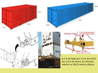
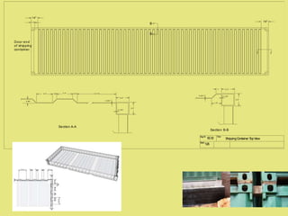
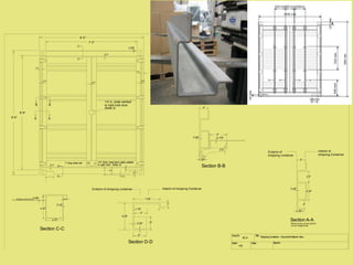
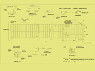
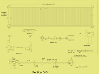
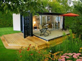
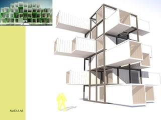
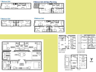
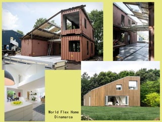
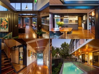
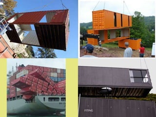
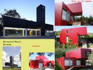
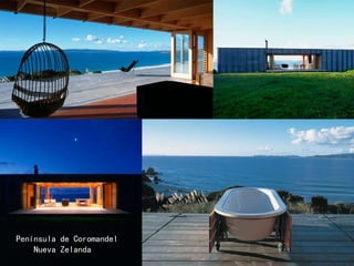
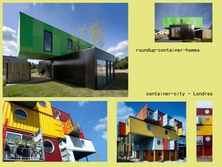
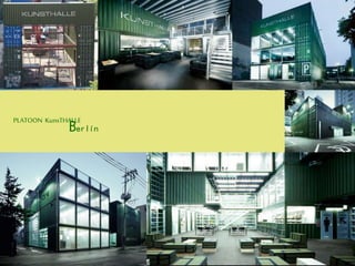
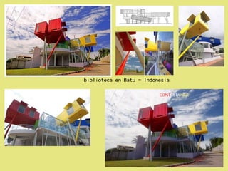
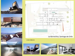
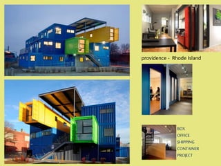
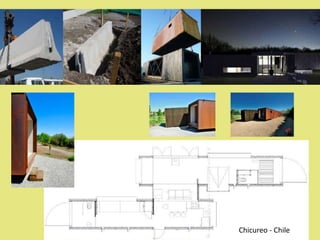
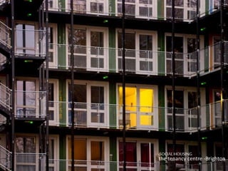
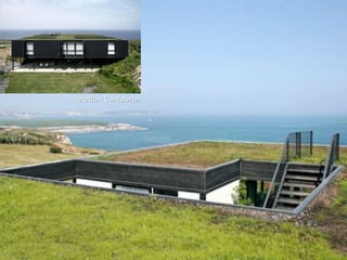
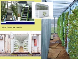
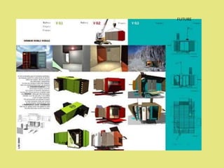
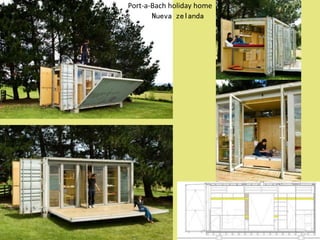
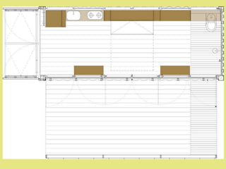
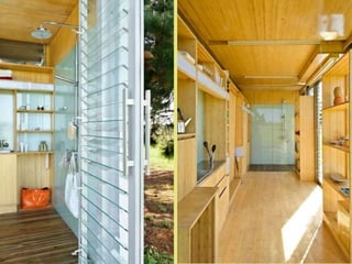
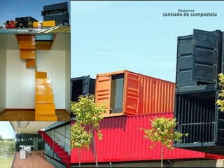
SHIPPING
CONTAINER
HOUSING
SYSTEM
Martínez Rodríguez, Miguel Ángel
Tilbury Docks(Reino Unido)
Binhai(China)
Port Botany(Australia)
Barcelona(España)
Yibuti(Yibuti)
Rotterdam(Holanda)
Hamburgo(Alemania)
TEU :acrónimo del término en inglés Twenty-foot Equivalent Unit
FEU :acrónimo del término en inglés Forty-foot Equivalent Unit
6,1 m de largo por 2,4 m de ancho
por 2,6 m de altura. Su volumen
exterior es 38,51 metros cúbicos.
Dwg Nr. Title:
Scale:
1:25
ShippingContainer TopView
0.8"3.3"
Door end
of shipping
container.
0.86" 0.081"
0.135"
2.5"
2.5"
12.75"
A A
Section A-A
0.081" 0.135"
2.5"
2.5"
3.3" 0.8"
1"
1.8"
Section B-B
B
B
14"
7.5" 15"
SC-12
DwgNr. Title:
Scale: Date: Signed:
1:20
ShippingContainer - DoorsEndExterior View
C
C
8' 9"
9' 6"
7' 0"
8' 0"
0.25"
2"
6.25"7"
3.25"
0.75"7"
Section D-D
Exterior of shipping container Interior of shipping Container
3"
3"0.25"
1"
1.75"
3"
6.25"
D
D
7.25"
0.19"
0.87"
4.37"
4.37"
1"0.08"Shipping Container Roof
Section C-C
Section A-A
0.25"
Shows only corner postin
a non-hinge area.
1.25"
2"
2.5"
4.37"
2"
AA
2.5"
2.5"
Exterior of
shipping container
Interior of
shipping Container
Section B-B
0.175"
4"
0.5"
0.25"
1.25"
2"
BB
Notes:
1. Standard shipping container securing bars, latches and related mounting hardware
are not shown as these are removed and/or not relevant to the strength or structural
integrity of the unit.
2. Weld beads are placed at the top of each hinge as part of securing the doors closed.
1/4 in. plate welded
to right side door.
(Note 3)
1" long steel 'pin' 1/4" thick steel latch plate welded
to right door. (Note 4)
3. Steel plate of right door welded to left door to ensure securely closed doors
4. Steel plate of right door welded to pin on left door.
5. Rubber sealing gaskets around doors not shown.
0.75"
0.75" 0.75"
0.75"
0.75"
SC-9
1"
DwgNr. Title:
Scale: Date: Signed:
1:40
UndersideFramingofShippingContainer-Sheet1of2
Door End
A
A
Section A-A
5.875 "
2.0 "1.125"
0.21"
B B
Section B-B
4.875"
0.18"
1.8"
Lateral C-beam (Narrow)
Longitudinal C-beam
12.67"
Lateral C-beams
12.67" on center &
welded to longitudinal
C-beams
8' 0"
End view - see
drawing #
B B
3' 7"
1' 7.5"
4.75"
4.75"
1' 7.5"
2"
2"
2.25"
2.25"
Lateral C-beams
12.67" on center &
welded to longitudinal
beams at either end.
12.67"
10' 11"
7"
7"
6"
3"
C C
Underside
of Container
Floor side of
container
undercarriage
Open portion of C-beam
faces toward doors
Section C-C
0.18 "
Wall
thickness
6"
4.75"
1"
0.18"
Underside of
container
floorcarriage
Upper (floor) side
of container
undercarriage
Door end
of shipping
container
Inner & outer channels
welded together along
upper edge of outter channel
D
D
E E
Per Section C-C
3.5"2.5"
0.18"6" 4" 6" 4"
U-beam welded to
upper plate along
entire length both edges.
Section E-E
4.75"
3.75"1"
2"
3.75"
4.75"
0.18 "
Wall
thickness
Section D-D
Container
center-line
direction.
Inner & outer channels
welded together along
upper edge of outter channel
Underside of
container
floorcarriage
Lateral C-beam (Wide)
Section F-F
4.875"
0.18"
3.6"
Open portion of C-beam
faces toward doors
1.8"
0.375"
0.375"
F F
G
G
Section G-G
4.5" 0.18"
Under side of
container
undercarriage
Under side of
container
undercarriage
19.25"
36.5"
36.5"
19.25"
40' 0" For more detail
see drawing
#
H
H
J
J
K
K
Section K-K
1.25 "1.25"
1.25 "
1.25 "
0.125"
(Longitudinal centerline
floor support.)
0.8"
SC-4a
DwgNr. Title:
Scale: Date: Signed:
1:25
ShippingContainer Exterior SideView
Door end
of shipping
container.
7.25"
9"
5"
7.25"
9"
5"
A A
7.25"
5"
5"
7.25"
B
B
2.75" 2.75" 2.75"2.75"2.75"2.75"
0.08"
1.4"
Section A-A 0.081" 0.135"
2.5"
2.5"
1"
1.8"
Section B-B
Section C-C
0.175"
4"
0.5"
0.25"
1.25"
2"
Range of corrugated wall per SectionA-A
Corrugated
Wall
Pair ofDoors (cont'd)
Corrugated
Wall
C C
D D
Section D-D
0.081"
2.5"
0.5"
0.25" 1.75"
1.5" 1.5"
2.5"2.5"
0.25"
6.8"
2.25"
2.25"
1.25"
6.125"
1.25"
3"
3"
0.5"
Corrugated s ide wall welded
along length to v ertic al end pos t
Vertic al s upport pos t welded
along periphery to top & bottom
bloc k s
SC-10
Section D-D
0.081"
2.5"
0.5"
0.25" 1.75"
1.5" 1.5"
2.5"2.5"
0.25"
6.8"
2.25"
2.25"
1.25"
6.125"
1.25"
3"
3"
0.5"
Corrugated side wall welded
along length to vertical end post
Vertical support post welded
along periphery to top & bottom
blocks
DIAMONDPIER
MoDULAR
World Flex Home
Dinamarca
FITING
Mooney House
Peavy Road-Dallas
COLLAPSIBLE
SHIPPING
CONTAINER
FINISHING
Barneveld Noord
Holanda
Casa en Tarragona
Península de Coromandel
Nueva Zelanda
roundup-container-homes
container-city - Londres
PLATOON KunsTHALLE
Berlín
CONTERTAINER
biblioteca en Batu - Indonesia
CASAORUGA
Lo Barnechea, Santiago de Chile
BOX
OFFICE
SHIPPING
CONTAINER
PROJECT
providence - Rhode Island
CASAENLA RESERVA
Santiago de Chile
Chicureo - Chile
EDUCATIONCENTERPROJECT
los ángeles - California
SOCIALHOUSING
the tenancy centre -Brighton
GREEN
habitat container - Argentina
loredo - Cantabria
urban farmer box - Berlín
FUTURE
Port-a-Bach holiday home
Nueva zelanda
lo-tek
Mazorros
santiado de compostela
fi n

Sistema constructivo cargo containers

  • 1.
  • 2.
  • 3.
  • 4.
  • 5.
  • 6.
  • 7.
  • 8.
  • 12.
    TEU :acrónimo deltérmino en inglés Twenty-foot Equivalent Unit FEU :acrónimo del término en inglés Forty-foot Equivalent Unit
  • 20.
    6,1 m delargo por 2,4 m de ancho por 2,6 m de altura. Su volumen exterior es 38,51 metros cúbicos.
  • 22.
    Dwg Nr. Title: Scale: 1:25 ShippingContainerTopView 0.8"3.3" Door end of shipping container. 0.86" 0.081" 0.135" 2.5" 2.5" 12.75" A A Section A-A 0.081" 0.135" 2.5" 2.5" 3.3" 0.8" 1" 1.8" Section B-B B B 14" 7.5" 15" SC-12
  • 23.
    DwgNr. Title: Scale: Date:Signed: 1:20 ShippingContainer - DoorsEndExterior View C C 8' 9" 9' 6" 7' 0" 8' 0" 0.25" 2" 6.25"7" 3.25" 0.75"7" Section D-D Exterior of shipping container Interior of shipping Container 3" 3"0.25" 1" 1.75" 3" 6.25" D D 7.25" 0.19" 0.87" 4.37" 4.37" 1"0.08"Shipping Container Roof Section C-C Section A-A 0.25" Shows only corner postin a non-hinge area. 1.25" 2" 2.5" 4.37" 2" AA 2.5" 2.5" Exterior of shipping container Interior of shipping Container Section B-B 0.175" 4" 0.5" 0.25" 1.25" 2" BB Notes: 1. Standard shipping container securing bars, latches and related mounting hardware are not shown as these are removed and/or not relevant to the strength or structural integrity of the unit. 2. Weld beads are placed at the top of each hinge as part of securing the doors closed. 1/4 in. plate welded to right side door. (Note 3) 1" long steel 'pin' 1/4" thick steel latch plate welded to right door. (Note 4) 3. Steel plate of right door welded to left door to ensure securely closed doors 4. Steel plate of right door welded to pin on left door. 5. Rubber sealing gaskets around doors not shown. 0.75" 0.75" 0.75" 0.75" 0.75" SC-9
  • 24.
    1" DwgNr. Title: Scale: Date:Signed: 1:40 UndersideFramingofShippingContainer-Sheet1of2 Door End A A Section A-A 5.875 " 2.0 "1.125" 0.21" B B Section B-B 4.875" 0.18" 1.8" Lateral C-beam (Narrow) Longitudinal C-beam 12.67" Lateral C-beams 12.67" on center & welded to longitudinal C-beams 8' 0" End view - see drawing # B B 3' 7" 1' 7.5" 4.75" 4.75" 1' 7.5" 2" 2" 2.25" 2.25" Lateral C-beams 12.67" on center & welded to longitudinal beams at either end. 12.67" 10' 11" 7" 7" 6" 3" C C Underside of Container Floor side of container undercarriage Open portion of C-beam faces toward doors Section C-C 0.18 " Wall thickness 6" 4.75" 1" 0.18" Underside of container floorcarriage Upper (floor) side of container undercarriage Door end of shipping container Inner & outer channels welded together along upper edge of outter channel D D E E Per Section C-C 3.5"2.5" 0.18"6" 4" 6" 4" U-beam welded to upper plate along entire length both edges. Section E-E 4.75" 3.75"1" 2" 3.75" 4.75" 0.18 " Wall thickness Section D-D Container center-line direction. Inner & outer channels welded together along upper edge of outter channel Underside of container floorcarriage Lateral C-beam (Wide) Section F-F 4.875" 0.18" 3.6" Open portion of C-beam faces toward doors 1.8" 0.375" 0.375" F F G G Section G-G 4.5" 0.18" Under side of container undercarriage Under side of container undercarriage 19.25" 36.5" 36.5" 19.25" 40' 0" For more detail see drawing # H H J J K K Section K-K 1.25 "1.25" 1.25 " 1.25 " 0.125" (Longitudinal centerline floor support.) 0.8" SC-4a
  • 25.
    DwgNr. Title: Scale: Date:Signed: 1:25 ShippingContainer Exterior SideView Door end of shipping container. 7.25" 9" 5" 7.25" 9" 5" A A 7.25" 5" 5" 7.25" B B 2.75" 2.75" 2.75"2.75"2.75"2.75" 0.08" 1.4" Section A-A 0.081" 0.135" 2.5" 2.5" 1" 1.8" Section B-B Section C-C 0.175" 4" 0.5" 0.25" 1.25" 2" Range of corrugated wall per SectionA-A Corrugated Wall Pair ofDoors (cont'd) Corrugated Wall C C D D Section D-D 0.081" 2.5" 0.5" 0.25" 1.75" 1.5" 1.5" 2.5"2.5" 0.25" 6.8" 2.25" 2.25" 1.25" 6.125" 1.25" 3" 3" 0.5" Corrugated s ide wall welded along length to v ertic al end pos t Vertic al s upport pos t welded along periphery to top & bottom bloc k s SC-10 Section D-D 0.081" 2.5" 0.5" 0.25" 1.75" 1.5" 1.5" 2.5"2.5" 0.25" 6.8" 2.25" 2.25" 1.25" 6.125" 1.25" 3" 3" 0.5" Corrugated side wall welded along length to vertical end post Vertical support post welded along periphery to top & bottom blocks
  • 26.
  • 29.
  • 31.
  • 34.
  • 36.
  • 37.
  • 38.
  • 39.
  • 40.
  • 41.
  • 42.
  • 43.
  • 44.
  • 45.
  • 46.
  • 47.
  • 48.
  • 49.
  • 50.
  • 51.
  • 52.
  • 53.
  • 56.
  • 57.
  • 58.