The document provides an overview of the finite element formulation for the free vibration analysis of laminated composite plates and shells. It begins with introducing the material and motivation for the study. Key aspects of the finite element formulation are then summarized, including:
1) Deriving the displacement fields incorporating shear deformation effects using a nine-noded element.
2) Developing the strain-displacement relations and stress-strain relationships.
3) Assembling the element stiffness matrix accounting for extensional, bending, and shear stiffnesses.
4) Computing the mass matrix through lumping the consistent mass matrix with and without rotary inertia effects.


![ Free vibration analysis of composite laminates with and without cut-outs:
Reference Type of Laminate Approach Target Response
Olson and
Lindberg
[1971]
Shallow isotropic
shells
Shallow shell theory of
Novozhilo and
Experimental Investigations
Natural frequencies and mode shapes
Jenq et al.
[1993]
GRP cross-ply plates
Shear deformation theory
and Experimental
Investigations
Effects of the size of cut-outs, the
location of defectson the vibration
frequencies
Singh and Kumar
[1996]
Doubly curved
laminated shallow
shells
First order composite
shell theory
Free vibrational characteristics of shells
on quadrangular planforms
Qatu
[1999]
Laminated composite
deep/thick shells
First order shear
deformation theory
Accurate stress resultants
Ganeson and
Kadoli
[2004]
Isotropic
hemispherical shells
First order shear
deformation theory
Thermo-elastic buckling analysis and
free vibration analysis of shells with
cut-out at apex due to uniform
temperature rise
Shi et al.
[2004]
Arbitrarily laminated
plate
Galerkin method Free vibration analysis
Hota and Padhi
[2007]
Plates with cut-outs
First order shear
deformation
Free vibration of plates with arbitrary
shapes of cut-outs
Ulz and
Semercigil [2008]
Plates
ANSYS and Experimental
Investigations
Use of cut-out as a
dynamic vibration absorber
Asadi et al.
[2012]
Thick deep laminated
cylindrical shells
3D and various shear
deformation theories
Static and vibration analysis
Thakur and Ray
[2015]
Deep doubly curved
laminated shell
HSDT
Free vibration analysis
Chapter II
(Contd.)
6.11.2019](https://image.slidesharecdn.com/shell-240216190415-c9c6c68d/75/shear-deformation-theory-of-shell-structure-pptx-5-2048.jpg)

![Reference Type of Laminate Approach Target Response
Kandasamy
and Singh
[2006]
Isotropic skew open
circular cylindrical
shells
Modified version of the
Rayleigh-Ritz method
Free vibration
analysis
Liew et al.
[2003]
Symmetrically
laminated plates
Moving least squares
differential quadrature
method based on FSDT
Free vibration
analysis
Vimal et al.
[2014]
Moderately thick
functionally graded
skew plates
FSDT
Free vibration
analysis
Park et al.
[2008]
Skew sandwich plates
with laminated
composite faces
HSDT
Dynamic
response
Kumar et al.
[2013]
Laminated composite
skew hypar shells
HSDT
Free vibration
analysis
Dey et al.
[2016]
Composite plates HSDT
Free vibration
analysis
Free vibration analysis of skew composite plates and shells:
Chapter II
(Contd.)
6.11.2019](https://image.slidesharecdn.com/shell-240216190415-c9c6c68d/75/shear-deformation-theory-of-shell-structure-pptx-7-2048.jpg)
![Reference Type of Laminate Approach Target response
Lee
[2010]
Plate HSDT
Dynamic stability
analysis
Murthy et al.
[2013]
Skew plate with
circular cut-out
ANSYS
Free vibration
analysis
Chapter II
(Contd.) Free vibration analysis of skew composite plates and shells
with cut-out:
6.11.2019](https://image.slidesharecdn.com/shell-240216190415-c9c6c68d/75/shear-deformation-theory-of-shell-structure-pptx-9-2048.jpg)

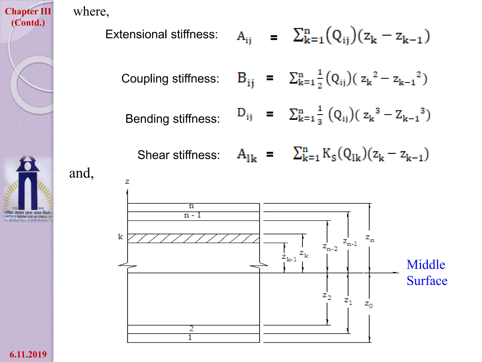
![Assumptions:
Middle surface of the shell is considered as reference plane
Effect of shear deformation is incorporated following the
Mindlin’s hypothesis
The shallow shell theory is used in the present formulation
Chapter III
-: FINITE ELEMENT FORMULATION :-
1 2 3
4
5
6
7
8 9
Fig. 3.1: Plan view of nine
nodded element
9 9
1 1
r r r r
r r
x N x and y N y
where,
Xr , Yr = co-ordinates of the r-th nodal point
Nr = Lagrangian interpolation function
[1]
6.11.2019](https://image.slidesharecdn.com/shell-240216190415-c9c6c68d/75/shear-deformation-theory-of-shell-structure-pptx-12-2048.jpg)
![Fig. 3.2: Deformation of shell panel in xz - plane
Chapter III
(Contd.) Effect of shear deformation:
x
x
y
y
w
x
w
y
øx & øy = Average shear rotation
over the entire plate or
shell thickness
θx & θy = Total rotations in bending
[2]
6.11.2019](https://image.slidesharecdn.com/shell-240216190415-c9c6c68d/75/shear-deformation-theory-of-shell-structure-pptx-13-2048.jpg)
![9 9 9
1 1 1
9 9
1 1
, , ,
r r r r r r
r r r
x r r y r y
r r
u N u v N v w N w
N and N
[3]
[4]
[5]
Chapter III
(Contd.) The displacement fields at a point within the element:
The stress resultant-strain relationship:
{F} = [D] {ε}
where,
{F}T = [ Nx N y Nxy Mx My Mxy Qx Qy]
6.11.2019](https://image.slidesharecdn.com/shell-240216190415-c9c6c68d/75/shear-deformation-theory-of-shell-structure-pptx-14-2048.jpg)


![
y
x
y
x
y
x
x
y
w
x
w
x
y
y
x
x
v
y
u
R
w
y
v
R
w
x
u
y
/
/
/
/
/
/
/
/
/
/
/
/
and
and,
[6]
[7]
11 12 16 11 12 16
21 22 26 21 22 26
61 62 66 61 62 66
11 12 16 11 12 16
21 22 26 21 22 26
61 62 66 61 62 66
55 54
45 44
0 0
0 0
0 0
0 0
0 0
0 0
0 0 0 0 0 0
0 0 0 0 0 0
A A A B B B
A A A B B B
A A A B B B
B B B D D D
D
B B B D D D
B B B D D D
A A
A A
Chapter III
(Contd.)
6.11.2019](https://image.slidesharecdn.com/shell-240216190415-c9c6c68d/75/shear-deformation-theory-of-shell-structure-pptx-17-2048.jpg)
![or, in short
yr
xr
r
r
r
r
r
r
r
r
r
r
r
r
r
r
Y
r
x
r
w
v
u
N
y
N
N
x
N
x
N
y
N
y
N
x
N
x
N
y
N
R
y
N
R
x
N
9
1
0
0
0
0
0
0
0
0
0
0
0
0
0
0
0
0
0
0
0
0
0
0
1
0
0
0
1
0
9
1
r
e
r
r
B
B
[9]
[10]
[8]
Chapter III
(Contd.)
6.11.2019](https://image.slidesharecdn.com/shell-240216190415-c9c6c68d/75/shear-deformation-theory-of-shell-structure-pptx-19-2048.jpg)
![Mass matrix:
1 1
1 1
T
e
K B D B J d d
The elemental stiffness matrix:
[12]
[11]
MLWORI (mass lumping without rotary inertia)-
(i=1,2,3,6,7,8,11,12,13,16,17,18,21,22,23,
26,27,28,31,32,33,36,37,38,41,42,43)
=
MLWRI (mass lumping with rotary inertia)-
(i=1,2,3,6,7,8,11,12,13,16,17,18,21,
22,23,26,27,28,31,32,33,36,37,38,41,42,43)
=
(i=4,9,14,19,24,29,34,39,44)
=
( i=5,10,15,20,25,30,35,40,45)
=
Chapter III
(Contd.)
[M] = ρh ∫∫ [N]T [N] dx dy
[13]
[14]
[15]
[16]
6.11.2019](https://image.slidesharecdn.com/shell-240216190415-c9c6c68d/75/shear-deformation-theory-of-shell-structure-pptx-20-2048.jpg)
![The stiffness matrix and mass matrix having an order of 45×45 are
evaluated for all the elements and they are assembled together to
form the overall stiffness matrix [K0] and mass matrix [M0]. Once
[K0] and [M0] are obtained. The equation of motion may be
expressed as-
[K0]{δ} = 2[M0] {δ}
After incorporating the boundary conditions in the above equation it
has been solved to get frequency for first four modes.
[17]
Chapter III
(Contd.)
6.11.2019](https://image.slidesharecdn.com/shell-240216190415-c9c6c68d/75/shear-deformation-theory-of-shell-structure-pptx-21-2048.jpg)


