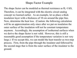
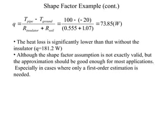
Shape Factor Example
The shape factor can be modeled as thermal resistance as Rt=1/kS,
Therefore, it can be integrated with the electric circuit analog
concept we learned earlier. As an example, let us place a thick
insulation layer with a thickness of 10 cm around the pipe line.
Now, determine the heat loss. (Caution: the following calculation
will be an approximation only since after we put on insulation the
outer surface of the insulation will not be constant temperature
anymore. Accordingly, the assumption of isothermal surfaces when
we derive the shape factor is not valid. However, this is still a
reasonable good assumption if the temperature variation is not very
large.) If we accept this, we can model the heat transfer as two-step
process. First, from the pipe through the insulator and followed by
the second stage that is from the outer surface of the insulator to the
ground.
Shape Factor Example (cont.)
Pipe through insulator
Insulator through the soil to the ground
Rsoil=1/kS
R
r r
k L
insulator
insulator

ln( / )
2 1
2
 
soil
2
2 1
The thermal resistance from the insulator to the ground is
1 1 1
R 0.555( / )
2 .1
2 0.5
ln(4 / ) ln(4/0.7)
ln( / ) ln(0.35/0.25)
1.07( / )
2 2 (0.05).1
soil
soil
insulator
insulator
C W
k S L
k
z D
r r
R C W
k L


 
    
 
 
 
   
D2: outer diameter
D1: pipe diameter
Tpipe
Tground
Shape Factor Example (cont.)
q
T T
R R
W
pipe ground
insulator soil




 


100 20
0 555 107
7385
( )
( . . )
. ( )
• The heat loss is significantly lower than that without the
insulator (q=181.2 W)
• Although the shape factor assumption is not exactly valid, but
the approximation should be good enough for most applications.
Especially in cases where only a first-order estimation is
needed.

shape factor configuration and view factor

  • 1.
    Shape Factor Example Theshape factor can be modeled as thermal resistance as Rt=1/kS, Therefore, it can be integrated with the electric circuit analog concept we learned earlier. As an example, let us place a thick insulation layer with a thickness of 10 cm around the pipe line. Now, determine the heat loss. (Caution: the following calculation will be an approximation only since after we put on insulation the outer surface of the insulation will not be constant temperature anymore. Accordingly, the assumption of isothermal surfaces when we derive the shape factor is not valid. However, this is still a reasonable good assumption if the temperature variation is not very large.) If we accept this, we can model the heat transfer as two-step process. First, from the pipe through the insulator and followed by the second stage that is from the outer surface of the insulator to the ground.
  • 2.
    Shape Factor Example(cont.) Pipe through insulator Insulator through the soil to the ground Rsoil=1/kS R r r k L insulator insulator  ln( / ) 2 1 2   soil 2 2 1 The thermal resistance from the insulator to the ground is 1 1 1 R 0.555( / ) 2 .1 2 0.5 ln(4 / ) ln(4/0.7) ln( / ) ln(0.35/0.25) 1.07( / ) 2 2 (0.05).1 soil soil insulator insulator C W k S L k z D r r R C W k L                    D2: outer diameter D1: pipe diameter Tpipe Tground
  • 3.
    Shape Factor Example(cont.) q T T R R W pipe ground insulator soil         100 20 0 555 107 7385 ( ) ( . . ) . ( ) • The heat loss is significantly lower than that without the insulator (q=181.2 W) • Although the shape factor assumption is not exactly valid, but the approximation should be good enough for most applications. Especially in cases where only a first-order estimation is needed.