SlideShare a Scribd company logo
1 of 142
Download to read offline
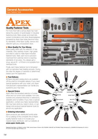
SP-1020EU 0912
Specifications subject to change without notice.
COPYRIGHT © 2012 APEX TOOL GROUP, LLC.
Apex Tool Group, LLC
14600 York Rd. Suite A
Sparks, MD 21152
US Phone: 800-688-8949
US Fax: 800-234-0472
www.apextoolgroup.com
CLECO/DGDDCELECTRICASSEMBLYTOOLSwww.apexpowertools.comwww.apexpowertools.euSP-1020EU0912
Power Tools Sales & Service Centers
Please note that all locations may not service all products. Please contact the nearest Apex Tool Group Sales & Service Center for the
appropriate facility to handle your service requirements.
D etroit , M ic h iga n
Apex Tool Group
Sales & Service Center
2630 Superior Court
Auburn Hills, MI 48326
Tel:	 (248) 393 5640
Fax:	 (248) 391 6295
Ho u sto n , T e x as
Apex Tool Group
Sales & Service Center
6550 West Sam Houston
Parkway North, Suite 200
Houston, TX 77041
Tel:	 (713) 849 2364
Fax:	 (713) 849 2047
S eattle , W as h i n gto n
Apex Tool Group
Sales & Service Center
2865 152nd Ave N.E.
Redmond, WA 98052
Tel:	 (425) 497 0476
Fax: 	(425) 497 0496
L e x i n gto n , S C
Apex Tool Group
670 Industrial Drive
Lexington, SC 29072
Tel:	 (800) 845 5629
Tel:	 (803) 951 7544
Fax:	 (803) 358 7681
L os A n geles , C ali f or n ia
Apex Tool Group
Sales & Service Center
6881 Stanton Avenue, Unit B
Buena Park, CA 90621
Tel:	 (714) 994-1491
Fax: 	(714) 994-9576
Y or k , P e n n syl v a n ia
Apex Tool Group
Sales & Service Center
York Service Center
3990 E. Market Street
York, PA 17402
Tel:	(717) 755 2933
Fax:	 (717) 757 5063
B ra z il
Apex Tool Group
Sales & Service Center
Caixa Postal 692
18001-970 Sorocaba, SP
Brazil
Tel:	 +55 15 2383929
Fax:	 +55 15 2383260
C a n ada
Apex Tool Group
Sales & Service Center
5925 McLaughlin Road
Mississauga, Ont. L5R 1B8
Canada
Tel:	 (905) 501 4785
Fax:	 (905) 501 4786
C h i n a
Cooper (China) Co., Ltd.
An Apex Tool Group, LLC company
955 Sheng Li Road,
Heqing Pudong, Shanghai
China 201201
Tel:	 +86 21 28994176
Fax:	 +86 21 51118446
E N G L A N D
Apex Tool Group
GmbH & Co. OHG
C/O Spline Gauges
Piccadilly, Tamworth,
Staffordshire B78 2ER
United Kingdom
Tel:	 +44 1827 8741 28
Fax:	 +44 1827 8741 28
Fra n ce
Apex Tool Group SAS
25 rue Maurice Chevalier
B. P. 28
77831 Ozoir-la-Ferrière Cedex
France
Tel:	 +33 1 64 43 22 00
Fax:	 +33 1 64 43 17 17
G erma n y
Apex Tool Group
GmbH & Co. OHG
Industriestraße 1
73463 Westhausen
Germany
Tel:	 +49 (0) 73 63 81 0
Fax:	 +49 (0) 73 63 81 222
E-mail: info@apexpowertools.eu
HUN G A R Y
Apex Tool Group
Hungaria Kft.
Platànfa u. 2
9027 Györ
Hungary
Tel:	 +36 96 66 1383
Fax:	 +36 96 66 1135
M e x ico
Cooper Tools
de México S.A. de C.V.
An Apex Tool Group, LLC company
Vialidad El Pueblito #103
Parque Industrial Querétaro
Querétaro, QRO 76220
Mexico
Tel:	 +52 (442) 211 3800
Fax:	 +52 (442) 103 0443
www.apexpowertools.com
www.apexpowertools.eu
DC Electric Assembly Tools
1
Table of Contents
Introduction  .  .  .  .  .  .  .  .  .  .  .  .  .  .  .  .  .  .  .  .  .  .  .  .  .  .  .  .  .  .  .  .  .  .  .  .  .  .  .  .  .  . 	2-3
Product Descriptions  .  .  .  .  .  .  .  .  .  .  .  .  .  .  .  .  .  .  .  .  .  .  .  .  .  .  .  .  .  .  .  .  .  . 	4-25
Building A Safety Critical DC Fastening System  .  .  .  .  .  .  .  .  .  .  .  . 	26
Cordless Transducer Control Tools  .  .  .  . 	28
	 Right Angle Tools  .  .  .  .  .  .  .  .  .  .  .  .  .  .  .  .  .  .  .  .  .  .  .  .  .  .  .  .  .  .  .  .  .  .  . 	28
	 Pistol Tools  .  .  .  .  .  .  .  .  .  .  .  .  .  .  .  .  .  .  .  .  .  .  .  .  .  .  .  .  .  .  .  .  .  .  .  .  .  .  .  . 	29
	 Tube Nut Tools  .  .  .  .  .  .  .  .  .  .  .  .  .  .  .  .  .  .  .  .  .  .  .  .  .  .  .  .  .  .  .  .  .  .  .  .  . 	30
	 Crowfoot Tools  .  .  .  .  .  .  .  .  .  .  .  .  .  .  .  .  .  .  .  .  .  .  .  .  .  .  .  .  .  .  .  .  .  .  .  .  . 	31
Corded Transducer Control Tools  .  .  .  .  .  . 	32
	 Right Angle Tools  .  .  .  .  .  .  .  .  .  .  .  .  .  .  .  .  .  .  .  .  .  .  .  .  .  .  .  .  .  .  .  .  .  .  . 	32
	 Inline Tools .  .  .  .  .  .  .  .  .  .  .  .  .  .  .  .  .  .  .  .  .  .  .  .  .  .  .  .  .  .  .  .  .  .  .  .  .  .  .  .  . 	34
	 Pistol Tools . . . . . . . . . . . . . . . . . . . . . . . . . . . . . . . . . . . . . . . . .	36
	 Push-to-Start Tools .  .  .  .  .  .  .  .  .  .  .  .  .  .  .  .  .  .  .  .  .  .  .  .  .  .  .  .  .  .  .  .  .  . 	37
	 Inline Floating Spindle Tools .  .  .  .  .  .  .  .  .  .  .  .  .  .  .  .  .  .  .  .  .  .  .  .  .  .  . 	38
	 Hold & Drive Tools .  .  .  .  .  .  .  .  .  .  .  .  .  .  .  .  .  .  .  .  .  .  .  .  .  .  .  .  .  .  .  .  .  .  . 	40
	 Flush Socket Tools .  .  .  .  .  .  .  .  .  .  .  .  .  .  .  .  .  .  .  .  .  .  .  .  .  .  .  .  .  .  .  .  .  . 	41
	 Tube Nut Tools . . . . . . . . . . . . . . . . . . . . . . . . . . . . . . . . . . . . . .	42
	 Crowfoot Tools  .  .  .  .  .  .  .  .  .  .  .  .  .  .  .  .  .  .  .  .  .  .  .  .  .  .  .  .  .  .  .  .  .  .  .  .  . 	43
	 Right Angle Floating Spindle Tools  .  .  .  .  .  .  .  .  .  .  .  .  .  .  .  .  .  .  .  .  . 	44
Building A Quality Critical DC Fastening System  .  .  .  .  .  .  .  .  .  .  . 	46
Corded Current Control Tools  .  .  .  .  .  .  .  . 	48
	 Right Angle Tools  .  .  .  .  .  .  .  .  .  .  .  .  .  .  .  .  .  .  .  .  .  .  .  .  .  .  .  .  .  .  .  .  .  .  . 	48
	 Inline Tools .  .  .  .  .  .  .  .  .  .  .  .  .  .  .  .  .  .  .  .  .  .  .  .  .  .  .  .  .  .  .  .  .  .  .  .  .  .  .  .  . 	49
	 Pistol Tools  .  .  .  .  .  .  .  .  .  .  .  .  .  .  .  .  .  .  .  .  .  .  .  .  .  .  .  .  .  .  .  .  .  .  .  .  .  .  .  . 	50
	 Push-to-Start Tools  .  .  .  .  .  .  .  .  .  .  .  .  .  .  .  .  .  .  .  .  .  .  .  .  .  .  .  .  .  .  .  .  . 	51
	 Inline Floating Spindle Tools  .  .  .  .  .  .  .  .  .  .  .  .  .  .  .  .  .  .  .  .  .  .  .  .  .  . 	52
	 Hold & Drive Tools  .  .  .  .  .  .  .  .  .  .  .  .  .  .  .  .  .  .  .  .  .  .  .  .  .  .  .  .  .  .  .  .  .  . 	53
	 Flush Socket Tools  .  .  .  .  .  .  .  .  .  .  .  .  .  .  .  .  .  .  .  .  .  .  .  .  .  .  .  .  .  .  .  .  .  . 	54
	 Tube Nut Tools  .  .  .  .  .  .  .  .  .  .  .  .  .  .  .  .  .  .  .  .  .  .  .  .  .  .  .  .  .  .  .  .  .  .  .  .  . 	55
	 Right Angle Floating Spindle Tools  .  .  .  .  .  .  .  .  .  .  .  .  .  .  .  .  .  .  .  .  . 	56
	 Crowfoot Tools  .  .  .  .  .  .  .  .  .  .  .  .  .  .  .  .  .  .  .  .  .  .  .  .  .  .  .  .  .  .  .  .  .  .  .  .  . 	58
Building A Safety Critical Fixtured DC Fastening System  .  .  .  . 	60
Fixtured Transducer Control Tools  .  .  .  .  . 	62
	 Intelligent Spindles  .  .  .  .  .  .  .  .  .  .  .  .  .  .  .  .  .  .  .  .  .  .  .  .  .  .  .  .  .  .  .  .  .  . 	62
	 Intelligent Spindle Accessories  .  .  .  .  .  .  .  .  .  .  .  .  .  .  .  .  .  .  .  .  .  .  .  . 	88
	 Conventonal Fixtured Spindles  .  .  .  .  .  .  .  .  .  .  .  .  .  .  .  .  .  .  .  .  .  .  .  . 	90
	 Conventonal Fixtured Spindle Accessories .  .  .  .  .  .  .  .  .  .  .  .  .  .  . 	112
Controllers  .  .  .  .  .  .  .  .  .  .  .  .  .  .  .  .  .  .  .  .  .  . 	114
	 mPro400GC-M, -P, -S, -SG Panel Controllers  .  .  .  .  .  .  .  .  .  .  .  . 	114
	 mPro400GC-E, -I Controllers  .  .  .  .  .  .  .  .  .  .  .  .  .  .  .  .  .  .  .  .  .  .  .  .  . 	115
	 mPro400SG Controllers  .  .  .  .  .  .  .  .  .  .  .  .  .  .  .  .  .  .  .  .  .  .  .  .  .  .  .  .  .  . 	116
	Software  .  .  .  .  .  .  .  .  .  .  .  .  .  .  .  .  .  .  .  .  .  .  .  .  .  .  .  .  .  .  .  .  .  .  .  .  .  .  .  .  .  . 	119
Accessories  .  .  .  .  .  .  .  .  .  .  .  .  .  .  .  .  .  .  .  .  . 	121
	 Isolation Transformer  .  .  .  .  .  .  .  .  .  .  .  .  .  .  .  .  .  .  .  .  .  .  .  .  .  .  .  .  .  .  .  . 	121
	 Tool Cables  .  .  .  .  .  .  .  .  .  .  .  .  .  .  .  .  .  .  .  .  .  .  .  .  .  .  .  .  .  .  .  .  .  .  .  .  .  .  .  . 	122
	 Cordless Tool Accessories  .  .  .  .  .  .  .  .  .  .  .  .  .  .  .  .  .  .  .  .  .  .  .  .  .  .  . 	123
	 Corded Tool Accessories  .  .  .  .  .  .  .  .  .  .  .  .  .  .  .  .  .  .  .  .  .  .  .  .  .  .  .  .  . 	124
	 Balance Arms & Balancers  .  .  .  .  .  .  .  .  .  .  .  .  .  .  .  .  .  .  .  .  .  .  .  .  .  .  . 	128
General Accessories & Information  .  .  . 	130
	 Apex Bits & Sockets  .  .  .  .  .  .  .  .  .  .  .  .  .  .  .  .  .  .  .  .  .  .  .  .  .  .  .  .  .  .  .  . 	132
	 Conversion Charts  .  .  .  .  .  .  .  .  .  .  .  .  .  .  .  .  .  .  .  .  .  .  .  .  .  .  .  .  .  .  .  .  .  . 	134
	 Model Number Index  .  .  .  .  .  .  .  .  .  .  .  .  .  .  .  .  .  .  .  .  .  .  .  .  .  .  .  .  .  .  .  . 	137
	 Waranty & Lubrication  .  .  .  .  .  .  .  .  .  .  .  .  .  .  .  .  .  .  .  .  .  .  .  .  .  .  .  .  .  .  . 	140
Safety
Critical
Quality
Critical
Accessories
Controllers
Fixtured
Safety
Critical
Cleco's fastening technology is used globally and
across all industries. This technology is used in
Aerospace, Motor Vehicle, Offroad, Wind Energy,
Agriculture, and a great multitude of applications
within general industry where “quality critical”
requirements are the rule. In motor vehicle
environments across the globe, Cleco and DGD's
complete line of transducerized electric tools are
used in “safety critical” applications where spot-on
precision and traceability are required. And finally, in
one of the most demanding environments, our line of
DC electric tools are used in aircraft assembly where
“good enough” will never be acceptable.
Because of our drive for perfection, you can excel
in your job. Indeed, due to our uncommon focus on
total fastening solutions instead of just products, our
customers look upon us not merely as vendors, but
as strategic allies. And at Apex, we welcome the
challenge of leadership this imposes.
The Systems
Cleco's state of the art Tightening System delivers
unprecedented performance, productivity and
accountability in both “quality critical” and “safety
critical” assembly applications.
Durability, speed, and ergonomics are achieved using
the corded Cleco DC electric tools with a complete
line of tool configurations and an assortment of
controller options to choose from.
2
The Total Solution For Safety & Quality Critical Fastening Operations
The Cleco LiveWire™ system provides the most
cost-effective safety critical fastening solution available
in the world today. By marrying cordless tools and
WiFi communications, the operators gain the mobility
and flexibility they need to increase productivity and
reduce in-system damage costs. One line controller
managing up to 16 cordless tools while utilizing the
most up-to-date wireless encryption technology
provides a cost savings unparalleled in industry today.
­
When considering the cumulative impact of all these
components – the tools, the controllers, the software,
the flexibility, the accessories and the support – it is
easy to see why the Cleco Tightening System is the
benchmark for all DC electric tool systems.
3
Label Printer
Ethernet TCP/IP
System Bus
Fieldbus
Tool
Serial – RS232
Serial – RS232
Discrete I/O – 24vdc
Serial – RS232
Serial – RS232
Socket Tray
Wireless
Torque Wrench
Operator
ID
Barcode
Scanner
4
Cleco mPro400GC Global Controller
The Most Flexible, Cost-Effect
Introducing the Cleco mPro400GC Global Controller, the first controller for safety-critical applications that
offers unsurpassed levels of flexibility, connectivity, and serviceability while providing superb torque accuracy
and process control. This new controller incorporates the advanced technical features of the proven DGD
mPro system with the user-friendly software of the trusted Cleco TME controller, resulting in a powerful
control solution that offers impressive cost savings through unequalled flexibility.
Corded, Cordless, Or Fixtured ... All From One Controller
The Cleco mPro400GC Global Controller is compatible with all Cleco 18-48 Series DC electric corded
tools, LiveWire cordless tools, and all DGD and EMT fixtured spindles. That means fewer controllers and
cables are needed for your line. And that means savings…up to 50% over traditional systems.
Reduce System Costs Up To 50%
■	Configure up to 32 DC spindles in varying configurations.
	 Consult your Apex representative for details.
■	Facility Cost Savings
		•	Installation Expenses: Save on Ethernet and
			 power drops, controller stands, cable
			 management, labor to install and support
		• Production Expenses: One controller
			 means fewer backups, fewer repairs,
			 fewer headaches and one-time training
Control System
Customer
Control
System
Corded Hand Tool
DGD
Conventional
Spindles
DGD Intelligent Spindles
Unique Technology, Smallest Hardware Foot Print, Best TCO.
CPM3 system with
internal power
transformer
Data Server mPro Remote
Programming
Access
Point
5
tive Systems Controller...Ever
6
Cleco mPro400GC Global Controller
Universal connectivity begins with global auto-
sensing input voltage, 16 configurable inputs and
outputs, plus DeviceNet, Ethernet-IP, Profibus and
Profinet fieldbus standards. User-
friendly software mapping of discrete
and fieldbus selections provides
ultimate error-proofing control. Dual
fieldbus ports allow redundant
I/O mapping or expansion. Utilize
two different fieldbus standards
simultaneously for maximum flexibility.
The Cleco mPro400GC Global
Controller comes standard with a
system bus to manage internal data
flow and avoid burdening outside networks. It can
be utilized for rapid “grab and go” connectivity
to accessories, such as adding error-proofing
from socket trays, stack lights, or operator boxes.
Configurable software menus allow quick integration
into any process. With up to 32 configurable nodes
on the system bus, endless error-
proofing combinations are possible.
The system bus can manage
multiple secondary controllers in
combination with single and multi-
spindle stations. Spindle sequencing,
data management, and diagnostics
are just a few of the many functions
performed. In addition, DGD®
Fixtured Intelligent Spindles can
utilize the system bus to drive up to 30% of cost out
of a traditional system through cable reduction,
maximizing acquisition and facility cost savings.
Universal Connectivity
Ethernet
Connections (2)
USB Ports
(2 bottom, 1 front)
System Bus
Connection
Auto-Sensing
Voltage Input
GFCI
Serial Ports (2)
Digital
Input/Output
(16)
Redundant
Fieldbus
Interface
Tool Cable
Connector
Universal
Connectivity
■	 Auto-Sensing Voltage
■	 16 Configurable I/O’s
■	 Redundant Fieldbus
■	 Redundant Serial
	 and Ethernet Ports
■	 Isolated System Bus
7
Remote
Programming
Ethernet
TCP/IP
For Ultimate Flexibility
User
Friendly
GUI
Quick-
Start
Auto
Program
Option
Oscilloscope
Process
Management
In-Depth
Data
Management
Easy-To-
Read Run
Screen
Digital Image
Bolt
Sequencing
Rundown Data Storage
The mPro400GC supports TorqueNet, our data
collection and archiving software, as well as other
industry standard software packages. Protocols are
available for many of the standard products.
The Cleco mPro400GC Global Controller works
seamlessly with current protocols and offers
significant performance advantages over traditional
systems. Features include:
n	 A single software program that covers both
	 standard and fixtured applications
n	 Standard spindle sequencing and
	 reject management
n	 19 advanced fastening
	 control sequences standard
	 at no additional cost
n	 Remote programming software
	 with no licensing restrictions
n	 Touch screen display with
	 integrated alpha-numeric keyboard
No Software
Licensing!
8
Cleco mPro400GC Global Controller
Superior Serviceability For
Master/Primary Unit
Installation Flexibility
At only 10”w X 15”h X 15”d (254mm X 381mm X 381mm) and weighing
just 30 lbs. (13.6 kg.), the Cleco mPro400GC is smaller and lighter
than most traditional controllers. It can be lifted easily by a single
person and will mount just about anywhere.
10”x15”x15”
(254mm X 381mm X 381mm)
And Just
30lbs.
(13.6 kg.)
9
r Exceptional Ease-Of-Use
Secondary Unit
Quick Mount Bracket
No more templates and measuring mounting hole patterns...installation of the
mPro400GC is simple with a separate receiver bracket that makes locating
mounting holes easy. The unit then attaches directly to the bracket so the
installation is fast and foolproof.
Integrated Cable
Management
The mPro400GC mounting bracket
incorporates an integral cable management
channel, so installations stay orderly and easily
accessible. Clearly labeled connectors and top-down
cable routing means a clean installation with no
guesswork. Mounting was designed to be simple and
effective to get you up and running fast.
CompactFlash®
Memory
For Production Uptime
A standard CompactFlash card
reliably stores:
  n Operating system
  n Drivers
  n Network settings
  n Application parameters
  n Torque data
Positioned on the back of the unit for added security
and tamper resistance, the card is still easily accessible.
n Rapid controller swap with 50-second boot
  n No licensing or proprietary hardware
  n Card stores up to 10,000 rundowns
Secondary Controller Functionality
A secondary controller is controlled from a master or primary unit. It
has I/O for local error proofing and peripherals, plus a LCD for operator
feedback and troubleshooting.
50
Second
Boot!
10
Electric Nutrunners – Cordless Transducer Control
LiveWire®
Wireless Communications
LiveWire™
offers precision torque, angle
and speed control features for safety
critical fastening in an ergonomic,
wireless design.
With up to 1,700 rundowns per battery
charge or continuous power, your safety
critical applications are assured to never
run out of power.
LiveWire™
has been
designed and tested to
provide wireless
connectivity across the
harshest of machine-to-
machine environments.
All The Brains. All The P
Electronic
Intelligence
■ On-board controller with
	 power management
■ Integrated servo with I/O
	 signal handling
■ Auto sensing power
	intelligence
■ 512 cycle memory buffer
Digital Process Control
■ Auto bolt sequencing
■ Auto image selection
■ Configurable reject management
11
Configurable
LED Illumination
Power. And It’s Wireless.
Integrated Bar Code Scanner (optional)
■ Enables real-time bar code data collection
■ Programmable bit for Auto Parameter Select
■ Tool enable and disable configurability
Operator Display
■ Real-time interface
■ Redundant feedback
	 • Green LCD = OK
	 • Yellow LCD = Running
	 • Red LCD = NOK / Errors
	 • Green LED = OK
	 • Red LED = NOK
■ Configurable application buttons
12
The Most Cost-Effective Safe
Up To 50% Savings Over Traditional Systems!
Mobility is a major advantage with wireless communications. Cleco LiveWire™
marries the
freedom and flexibility of cordless tools with real-time wireless error proofing. Utilizing an
industry standard 2.4/5GHz WLAN (Wireless Local Area Network) interface in conjunction
with the highest security encryption and authentification levels, plus a 512-cycle tool
memory buffer, LiveWire™
ensures you will never
compromise safety critical
data transmissions.
Up To 16
LiveWire
Tools.*
1 Line
Controller.
*Contact Regional Application
Center for requirements
greater than 10.
Electric Nutrunners – Cordless Transducer Control
LiveWire®
Wireless Communications
12
2.4 or
5GHz
WLAN
13
ety Critical Solution Available
Wireless Security
■ WEP (Wired Equivalent Privacy)
      • 64/128 Bit Encryption
■ WPA (Wireless Protected Access)/WPA2/802.1x
      • 128 Bit TKIP/CCMP Encryption
      • 802.1x
		 Authentification pre-shared
	 	 keymode (PSK) - LEAP, PEAP
Up To 83% More Productivity!
Cleco LiveWire™
tools are now available with Vmax™
, a solution that drives tool power and speed
increases up to 83% without losing accuracy or durability. This leading innovation utilizes the same
10 tools to one line controller hardware solution with up to 50% cost savings over traditional systems.
New Vmax™
technology auto-senses the applied power source and adjusts the maximum tool
speed capability on the fly. LiveWire™
with Vmax™
combines the power you need with the most
	 versatile wireless system available today.
13
14
Durability. Speed.
Cleco 18-48 series tools are driven by a maintenance-free brushless motor with up to 50%
more speed and productivity. This motor technology coupled with our high-resolution resolver
offers full range control for safety critical joints. The 18-48 series tools with industry proven gear
trains create outstanding durable production performance.
The Cleco 18-48 series electric tools provide a unique modular assembly design for ease of
repair. The on-board intelligent memory chip records tool set-up values and counts
cycles for maintenance scheduling to prevent costly production downtime.
Highly visible operator
feedback LEDs
Intelligent
memory
chip
Low
compression
switch
Ergonomic handle for
operator comfort
Resolver technology
for full range
speed control
Tools shown with Apex® u-Guard™ protective covered industrial sockets. Cover spins independently of socket virtually eliminating damages
Error free
connector
(in tool handle)
Air-LB
(Tools with Matrix connector
available upon request.)
Electric Nutrunners – Corded Transducer Control
15
Ergonomics.
Optimal tool weight
and balance
Reaction transducer for
consistent torque
repeatability
Standard tools
required
for service
Durable
industry proven
gear train
s and risks associated with incidental contact between the tool and the workpiece or user. Not included with tool.
Adjustable
angle head allows
flexible orientationLow inertia brushless motor
for superior fastening control
16
Durability. SpeeCost Effective Solution for Quality Critical Applications.
Cleco CurrentControl electric assembly tools provide an up-sell solution to quality critical
applications presently specifying a pneumatic clutch tool and verifier combination. Cleco
proprietary CurrentControl systems up-sell on superior productivity, error proofing
and process flexibility.
Our Cleco controller systems are recognized globally for “best in class” software
interface. This is accomplished through simple navigation, basic
programming screens, visual programming graphics and real-time process
feedback. Our latest innovation “Auto Program” takes the guesswork out
of programming. Simply enter the application torque target and the
software automatically compiles the program for production use.
Adjustable
angle head
allows
flexible
orientation
Unrestricted
Speed Control
Electric Nutrunners – Corded Current Control
17
ed. Ergonomics.Why CurrentControl vs. Pneumatic Clutch?
Superior Productivity
n Up to 2–3X faster
n Unrestricted speed control
n Up to 25% less noise
n Cleaner operating environment
n Auto torque sequencing
n Proven production durability
Superior Process Flexibility
n 255 programmable tightening strategies
n 6 configurable stages per strategy
n Angle process control/monitoring
n Counter-clockwise process
control/monitoring
n Less parts to maintain – no clutch
n 100M field cable lengths
Superior Error Proofing
n 96 position fastener count
n 9 tool LED operator feedback
n 8 configurable I/O
n Fieldbus ready
n 5,000 tightening cycle storage
n Advanced system diagnostics
n Barcode application select
Easy Setup 1-2-3-Go!
1. Select “Basic” from menu. 2. Enter final torque value.
3. Tool automatically programmed. Go! Production ready.
18
Productivity That D
Intelligent Spindles
Introduced in 2005, DGD Intelligent Spindles were the
first fixtured nutrunners that offered onboard servo and
modular construction. Today, these third generation
nutrunners are based on over 50 years of proven
success of our conventional spindles.
DGD Intelligent Spindles combine high speed,
exceptional up time availability, and unprecedented
accuracy and durability in a compact design that
requires substantially less cabling than
traditional nutrunners. The result is
productivity gains at a lower cost,
with up to 30% savings on initial purchase price. DGD
Intelligent Spindles also offer easy integration with
Cleco electric tool products, including the new Cleco
Global Controller.
Up To 170% Faster
With sealed, long-life, maintenance-free 380
VDC motors, DGD Intelligent Spindles are
faster than a conventional spindle at most
every torque level.
	Compact
On-Board Intelligence
The on-board servo module is
proven technology that has been tested to:
• Shock & Vibration: 3 dimension at 13G
• Temperature : 45° C
• MTBF of 7 million cycles
Durability &
Accuracy
The BTS and BTSE
nutrunners are certified
to the highest standard of
accuracy and durability.
• ISO certified to
± 2% accuracy
• 1 million duty cycles
maintenance free
• 3 million cycle guaran-
tee @ 80% of capability
Reduced Field Cables
DGD Intelligent Spindles provide a solution for the
number-one cause of shut-down … cable failure
… by substantially reducing the number of cables
needed. Where DGD conventional spindles each
need a separate cable, up to 16 Intelligent Spindles
can be run from a single field cable by cascading
cables between spindles.
Field Cable
CPM3
DGD Speed Comparison
Torque
(Nm)
DGD
Conventional
Spindle
DGD
Intelligent
Spindle
DGD
RPM
Advantage
10 1222 1921 57%
50 329 890 170%
100 329 890 170%
150 219 502 137%
200 220 502 48%
19
Drives Cost Savings
Acquisition & Installation Costs plus Floor Space Are All Reduced
System Simplicity
Cost effective
DGD Intelligent System
Older and more expensive
DGD Conventional System
Savings with a DGD 10 Spindle
Intelligent Spindle System
vs. DGD Conventional System
In The Following Areas
Festooning Hardware
(including installation)
Installation Labor
System Field Cables
Replacement Spare Parts & Cables
Trouble Shooting Time
System Availability
Incredible $avings!
DGD Conventional Spindle
System Solution
DGD Intelligent Spindle
System Solution
DGD 10 Spindle
Requirements
Conventional Intelligent
10 Controllers 1
10 Field Cables 1
10
Power Interface
Points
1
5 hrs.
Cable Festooning
Time
1 hr.
5 hrs.
Controller
Installation Time
1 hr.
5 hrs.
Startup/Debug
Time
3
hrs.
6
sq.ft.
Required
Floor Space
3.5
sq.ft.
No
Ability to add
additional tools to
existing controller
Yes
$avings Time &
Material
Tools, Cables & Controller $
Installation $$$
Parts (cables & controllers) $
Total System $avings $$
✔
✔
✔
✔
✔
✔
20
Your Single Source For
Custom Automated Systems
Automated Systems provides custom solutions
for the automated fastening of threaded joints.
Our global customers span the entire vehicle
assembly market, including passenger cars and
trucks, power train assembly, off-road vehicles,
and agricultural machines. We support machine
tool builders in the vehicle and industrial markets
with custom fastening system designs based on
proven fastening product building modules.
Over many decades, Automated Systems has
been providing custom solutions for training,
service, and support. From single handheld
nutrunners to multiple spindle machines, our
custom designed systems are used around the
world in an interesting variety of applications.
We have a full support staff of Sales Engineers,
Mechanical Engineers, Controls Engineers,
Project Managers, Field Service Engineers and In
house Service Engineers waiting to serve you.
Custom Automated Solutions
The custom designed equipment Automated
Systems creates can be configured in either
vertical or horizontal orientations depending
on the application and customer requirements
Automated Systems
An automatic station on an engine assembly line uses two
opposing electric power heads, each having 8 spindles, and a
center power head of 6 spindles.
Shown are two semi-automatic DC electric systems
to secure camshaft cover fasteners and water pump
assembly mounting fasteners.
21
Automated Systems
The left
cylinder head of
a V12 engine is
being fastened using
a 26 spindle fixtured
electric multiple. The suspension
system has been designed to not
only support the weight of the
tool, but to rotate into fastening
alignment with the cylinder head
on the right side of the engine.
utilizing standard components. Designs may
incorporate operator input or be fully automated
dependent on the needs of the customer.
Automated Systems’ products use high-efficiency
electric motors manufactured specifically for
this application. Available motor torques range
from 2 Nm to 4,000 Nm. Motor spindles can
be mounted and arranged to match any pattern
using standard in-line, special offset, and 90°
angle electric motors.
In order to apply our powerhead designs, we also
design custom suspension systems along with
cable management systems to provide support
and movement. In addition to custom built
stations fitted with fixtured nutrunner powerheads,
Automated System designs, builds, installs and
provides service and support from the complete
fastening lines.
The above manually operated railroad wheel bearing multiple has the capability to tighten three (3) fasteners equally spaced on various
centers between 3.50” to 5.85” diameters up to 600 NM torque.
22
Wheelnut Fastening
Automated Systems is the recognized leader in the
design and manufacture of multiple spindle wheel-
nut assembly systems. We are known across the
globe for excellence of innovative engineering
design, support, and quality award winning service.
Decades of expertise in the design and manu-
facturing of multiple spindle fixtured and portable
assembly systems have identified Automated
Systems as an experienced, innovative supplier
capable of creating custom solutions matched to
unique customer assembly requirements.
Automated Systems makes use of standard sys-
tem building block components which are used
to blend a custom system from a complete line of
DC electric spindles, fastening controllers and an
extensive listing of twenty-four different fastening
strategies which not only include the usual Torque
Control, Angle Control and Yield, but also includes
the unusual Pulse Torque Recovery makeup
torque fastening strategy awarded US Patent
number 5,094,301.
Medium Duty Wheelnut Tool
For Passenger Vehicles requiring
Medium Torque, High Volume
• 100 Nm to 500 Nm
Automated Systems supplies custom Wheelnut
multiple designs using standard major com-
ponents with proven track records for reliability,
lifetime performance, millions of cycles capability
and ergonomic solutions which support operator
safety, comfort and efficiency.
Heavy Duty Wheelnut Tool
For Trucks requiring High Torque,
Low Volume
• 700 Nm to 1200 Nm
Automated Systems Wheelnut multiples use high-
efficiency electric motors manufactured specifically
for this application. Available motor torques range
from 700 Nm to 1200 Nm. Motor spindles can be
mounted and arranged to match any bolt circle
pattern, using standard in-line motors with or
without offset gearing.
Automated Systems
Wheelnut Fastening
23
Automated Systems
Wheelnut Fastening
Adjustable Wheel Stud Centers
When several similar wheels need to be assem-
bled and the economics of separate powerheads
dictates a single powerhead, Automated Systems
has the answer! Adjustable stud centers. The posi-
tion of the studs can be controlled by an operator
manual switch, or auto detection.
Budd Double Wheels
When it comes to fastening inner and outer wheel
lug nuts including Budd style stud/nut adapters,
a wheelnut powerhead requires long retractable
spindles which are designed to prevent side
loading. Automated Systems has the know-how,
and the products to supply wheelnut multiples for
double wheel truck applications. Our wheel equip-
ment is more rugged than the trucks it assembles.
Suspension
System
A properly designed
suspension system can
not only support the
tool and return it to a
home position, it can
also provide a zero grav-
ity lift and hold. The total
weight of the tool
is controlled by the
operator with very little
pressure required to
move the tool up or
down.
Local Operator Display
(Operator Interface)
Each powerhead
displays a red, green,
and yellow LED on a
per spindle basis. The
LED display indicates
the status of the last
tightening as NOK,
OK and Low Torque or
Angle. An optional local operator interface display
can be used to display output, and accept touch
screen switch inputs.
Some of the uses of a local operator display include:
• Application selection
• Tool home position jog
• Overall fastening status in green or red
• Part graphics
• Fastening values for torque and angle
• Functional push-button inputs & display outputs
24
Push-off and Return
On moving transfer lines, the overhead suspension system
can be mounted to an overhead track, supporting the
multiple. At the conclusion of the fastening rundown by all
spindles, the suspension pushes the tool away from the
wheel and returns the tool to the home position ready for
the next wheel. The vehicle on the assembly transfer line
continues to move while the lug nuts are being tightened.
Application Detection of
Aluminum and Steel Wheels
Wheel lug nut tools are distinguished from standard hori-
zontally aligned systems by their cylindrical shape. Rotation
of the tool is required for proper alignment with the wheel
lugs, and the ability to provide a clear line of sight for the
operator. In addition, a 6 spindle tool can be rotated 30
degrees, rundown a second time and tighten the alternate
6 lug nuts on a 12 lug nut wheel. This alternative design is
tightening dual truck wheels, and can automatically deter-
mine if the wheel is aluminum or steel and change the
fastening parameters automatically.
Automated Systems
Wheelnut Fastening
Shown are two
manually operated
vertical multiples and
one semi-automatic
DC electric systems.
25
Automated Systems
Intelligent Spindle Field Cables
Shown above is a ten Intelligent spindle application with nine jumper cables and a single
field cable that terminates at the power distribution box.
Shown above is a seven Intelligent spindle application with six jumper cables and a single field cable that terminates at
the power distribution box.
Reduced Field Cables
DGD Intelligent Spindles provide a
solution for the number-one cause
of shut-down … cable failure … by
substantially reducing the number
of cables needed. Where DGD
conventional spindles each need a
separate cable, up to 16 Intelligent
Spindles can be run from a single
field cable by cascading cables
between spindles. We offer both
HighFlex for fixed or flexible routing
for heavy duty requirements and
SuperHighFlex for robotic and all
high mobility applications. See
page 76 for more details.
Benefits of Intelligent
Spindle Field Cables
■ Lower cost of ownership
■ Higher durability
■ Lower start-up cost
■ Reduced cable
	 management systems
26
How To Build A DC Fastening System
mPro400GC-M, mPro400GC-P & mPro400GC-S
Building a DC System for Safety Critical applications
is as simple as 1, 2, 3!
	 1.	 Choose a common system to the right.
	 2.	 Select the correct components below.
	 3.	 Order your System!
Controller (Page 114)
Corded Tool (Page 32-44)
Cable (Page 121-122)
LiveWire Tool (Pages 28-31)
Access Point (Page 123)
IRDA Device (Infrared Cable) (Page 123)
System Bus Cable (Page 124)
System Bus Terminator Plug (Page 124)
System Bus Accessories (Page 124)
Isolation Transformer (Page 121)
(Refer to Pages 46-47 to build a mPro400GC-E/GC-I system.)
27
mPro400GC-M (Master) 1 1
mPro400GC-P (Primary) 1 1 1 1 1 1
mPro400GC-S (Secondary) 1 2
18/48E_EXXX 1 1 2 1 3
67E_XXX 1
Tool Cable - 301866-XM (Air-Lb) 1 1 2 1 3
Tool Cable - 542778-XM (Matrix) 1
Extension Cable - 301877-XM (If Required) (Air-Lb)
Extension Cable - 542779-XM (If Required) (Matrix)
17/47B___BXX
(Battery or V-Max power source required. See Page 123.)
1 1 3
544249PT 1 1 1
935170 IRDA Only
935144 Pistol Holder w/IRDA
935290 Right Angle Holder w/IRDA
935999 70Nm, 90Nm, Crowfoot/Tubenut Holder w/IRDA
1 1 1
544196-005 (0.5M)
544196-020 (2M)
544196-050 (5M)
544196-200 (20M)
544196-500 (50M)
1 2 1 2 3
544197PT 1 1 1 1 1
S133420 Stack Light 3
S133410 4-Position Socket Tray 1
S133411 8-Position Socket Tray 1
S133406 Control Box 1
544185PT 1
O
ne
C
orded
Tool(18/48E_E)
O
ne
C
orded
Tool(67E_XXX)w
ith
a
C
ontrolBox
O
ne
C
orded
Tool(18/48E_E)w
/LiveW
ire™
Tw
o
C
orded
Tools
(18/48E_E)w
ith
8-Pos
SocketTray
O
ne
C
orded
18/48E_E
Toolw
/4-Position
SocketTray
Three
C
orded
Tools
(18/48E_E)
O
ne
LiveW
ire™
Toolonly
Three
LiveW
ire™
Tools
O
nly
w
/3
Stack
Lights
Model/Part Number
Add or delete components
as required.
28
Electric Nutrunners – Cordless Transducer Control
Right Angle Tools
Data Transmission
X	–	2.4 GHz WLAN: WEP, WPA, WPA2, 802.1x
Y	–	Dual Band – 2.4/5 GHz WLAN: WEP, WPA, WPA2, 802.1x
Z	–	Xbee (4 tools/base station)
R	–	RF868MHz (4 tools/base station) EU only
Peripherals
S	–	Barcode Scanner
-	–	None
Motor
47
Tool Style
A – Angle
Power
B-Battery
	 47	B	A	X	X	B	XX	XXX	X
Max Torque (Nm)
Under 60Nm, rounded up to
the nearest 1Nm. Over 60Nm,
rounded to the nearest 5Nm.
Battery
B – 26–48V
Output Drive
AM3 – 3/8” Sq.Dr.
AH4 – 1/2” Sq.Dr.
Retainer
– Pin Retainer
B Ball Retainer
Cordless Tools Nomenclature
Right Angle Series
Torque Range	 Bolt Size
5.5 - 90 Nm	 M5 - M12
4.1 - 77.4 Ft. Lbs.	 #10 - 9/16”
■ Brushless precision
■ Resolver control
■ Transducer accuracy
■ On-board controller with
	 power management
■ Integrated servo with I/O
	 signal handling
47BAYSB28AM3
Right Angle Torque Range Free Speed (RPM)
Weight
Less Battery Output
Drive Size
Length With 26V Battery
Model Number Ft.Lbs. Nm 26V* 44V* Vmax lbs. kg in. mm
47BAYSB15AM3 4.1-11.1 5.5-15 538 983 983 4.77 2.17 3/8" SQ 21.79 553.5
47BAYSB21AM3 5.9-15.5 8-21 411 751 751 4.77 2.17 3/8" SQ 21.79 553.5
47BAYSB28AM3 7.4-20.7 10-28 291 532 532 4.77 2.17 3/8" SQ 22.32 567.5
47BAYSB35AM3 9.6-25.8 12-35 244 447 447 5.35 2.43 3/8" SQ 23.06 600.0
47BAYSB50AM3 13.3-36.9 18-50 168 293 293 5.39 2.45 3/8" SQ 23.94 608.0
47BAYSB70AH4 17.7-66.3 24-70 123 216 216 8.54 3.88 1/2" SQ 26.7 678.0
47BAYSB90AH4** 29.5-77.4 40-90 82 144 144 8.73 3.96 1/2" SQ 26.7 678.0
*Speed with fully charged battery.
**Non-released model available for specific applications only.
Contact Regional Application Center for implementation assistance.
General: All tools must be used with a Cleco approved line controller.
Standard Equipment: Integrated infrared communications.
Extra Equipment: See pages 123-125 for optional accessories.
(Apex u-Guard socket shown above not included)
29
Electric Nutrunners – Cordless Transducer Control
Pistol Grip Tools
17BPYSB13Q
Data Transmission
X	–	2.4 GHz WLAN: WEP, WPA, WPA2, 802.1x
Y	–	Dual Band – 2.4/5 GHz WLAN: WEP, WPA, WPA2, 802.1x
Z	–	Xbee (4 tools/base station)
R	–	RF868MHz (4 tools/base station) EU only
Peripherals
S	–	Barcode Scanner
-	–	None
Motor
17
Tool Style
P – Pistol
Power
B-Battery
	 17	B	P	X	X	B	XX	Q
Max Torque (Nm)
Under 60Nm, rounded up to
the nearest 1Nm.
Battery
B – 26–48V
Output Drive
Q – Quick change
Cordless Tools Nomenclature
Pistol Grip Series
Torque Range	 Bolt Size
3.0 - 13 Nm	 M5 - M6
2.2 - 9.6 Ft. Lbs.	 #10 - 1/4”
■ Brushless precision
■ Resolver control
■ Transducer accuracy
■ On-board controller with
	 power management
■ Integrated servo with I/O
	 signal handling
Pistol Torque Range Free Speed (RPM)
Weight
Less Battery Output
Drive Size
Length With 26V Battery
Model Number Ft.Lbs. Nm 26V* 44V* Vmax lbs. kg in. mm
17BPYSB05Q 2.2-3.7 3-5 1639 2428 2428 3.34 1.52 1/4" Hex 8.44 214.5
17BPYSB07Q 2.2-5.2 3-7 1161 1721 1721 3.34 1.52 1/4" Hex 8.44 214.5
17BPYSB09Q 2.2-6.6 3-9 887 1314 1314 3.34 1.52 1/4" Hex 8.44 214.5
17BPYSB13Q 2.2-9.6 3-13 629 931 931 3.34 1.52 1/4" Hex 8.44 214.5
*Speed with fully charged battery.
General: All tools must be used with a approved Cleco line controller.
Standard Equipment: Integrated infrared communications.
Extra Equipment: See pages 123-125 for optional accessories.
(Apex u-Guard socket
shown above not included)
30
Electric Nutrunners – Cordless Transducer Control
Tube Nut Tools
“B”
T2, T3 & T4
Head Height
“A”
2.63” (67 mm) 1.56” (40 mm)
T2 Head T3 Head
1.44” (37 mm)
“A”
“C”
“D”
T4 Head
1.94” (49 mm)
“A”
“C”
“D”
“C”
“D”
T3
T4
Tube Nut Series
Torque Range	 Bolt Size
10 - 40 Nm	 M6 - M8
7.4 - 29.5 Ft. Lbs.	 1/4” - 7/16”
■ Brushless precision
■ Resolver control
■ Transducer accuracy
■ On-board controller with
	 power management
■ Integrated servo with I/O
	 signal handling
47BTYSB20T2
The 47BT tube nut wrench alternates the
direction of rotation each time the lever is
actuated. When rotating in reverse, the
socket will stop at the open position.
Tube Nut Torque Range
Free
Speed (RPM)
Weight
Less Battery
Max.
Drive
Size
Length w/
26V Battery
Head
A Width B Blade Ht. C Opening D End/Cntr.
Model Number Ft.Lbs. Nm 26V* 44V* Vmax lbs. kg in. mm in. mm in. mm in. mm in. mm
47BTYSB20T2 7.4-14.8 10-20 260 455 455 5.6 2.54 1/2" 23.6 598 1.42 36 0.55 14 0.28 7 0.53 13
47BTYSB30T3 11.1-22.1 15-30 188 329 329 5.6 2.53 3/4" 23.3 588 1.65 42 0.59 15 0.475 12 0.73 19
47BTYSB40T4 14.8-29.5 20-40 141 247 247 6.4 2.90 1 1/16" 29.9 612 2.36 60 0.59 15 0.675 17 0.93 24
*Speed with fully charged battery.
General: All tools must be used with a Cleco approved line controller.
Standard Equipment: Integrated infrared communications.
Extra Equipment: See pages 123-125 for optional accessories.
To order individual sockets, use a “KS” prefix. (i.e. KS2EA01 for a T2, 1/4”, flush, thru hex socket.)
Tube Nut Tool Nomenclature Socket Nomenclature
Peripherals
S	–	Barcode Scanner
-	–	None
Battery
B-26V-48V
Series
47
Tool Style
T – Tube Nut
Power
B–Battery
Output Type
0 -Partial Thru Hex	 2 -Double Thru Hex
1 -Thru Hex	 3 -Partial Thru
	 Double Hex
Extension Length
0 – Flush	 4 – 1/2”
2 – 1/4”	 6 – 3/4”
Maximum Hex Socket Size
MG, EE	 T2 Head Type
MM	 T3 Head Type
MU	 T4 Head Type
00, ## (Specials)	 All Head Types
Socket Sizes
EA - 1/4”	 M5 – 5mm	 MH – 14mm	 MP – 22mm
EC – 3/8	 M6 – 6mm	 MI – 15mm	 MQ – 23mm
EE – 1/2	MA – 7mm	 MJ – 16mm (5/8”)	 MR – 24mm (15/16”)
EF – 9/16	 MB – 8mm (5/16)	 MK – 17mm	 MS – 25mm
EH – 11/16	 MD – 10mm	 ML – 18mm	 MT – 26mm
EJ – 13/16	 ME – 11mm (7/16)	 MM – 19mm (3/4”)	 MU – 27mm (1 1/16”)
EK – 7/8	 MF – 12mm	 MN – 20mm
EM – 1	 MG – 13mm	MO – 21mm
	 47	 B	 T	 X	 X	x	 XX	XX	KSX	XX	XX	X
Data Transmission
X	–	2.4 GHz WLAN: WEP, WPA, WPA2, 802.1x
Y	–	Dual Band – 2.4/5 GHz WLAN: WEP, WPA, WPA2, 802.1x
Z	–	Xbee (4 tools/base station)
R	–	RF868MHz (4 tools/base station) EU only
Head Type
T2 - 20 Nm
T3 - 30 Nm
T4 - 40 Nm
Thru Hex Double
Thru Hex
Partial
Thru Hex
Partial Thru
Double Hex
Head Type
KS2 – T2
KS3 – T3
KS4 – T4
Max Torque (Nm)
Under 60Nm, rounded up
to the nearest 1Nm. Over
60Nm, rounded to the
nearest 5Nm.
31
Electric Nutrunners – Cordless Transducer Control
Crowfoot Tools
.61”
(15.49)
.97”
(24.63)
.75”
(19)
3.00”
(76.2)
30°
R.63”
(16)
1.25”
(31.75)
1.50”
(38.1)
.25”
(6.35)
C3 – 30° Head (Part No. 301960)
Maximum Recommended Torque: 22 ft.lbs. (30 Nm)
15°
.61”
(15.49)
1.09”
(27.86)
.75”
(19)
3.00”
(76.2)
2.66”
(67.56)
1.50”
(38.1)
1.25”
(31.75)
R.63”
(16)
.25”
(6.35)
C1 – 15° Head (Part No. 301959)
Maximum Recommended Torque: 22 ft.lbs. (30 Nm)
Crowfoot Series
Torque Range	 Bolt Size
10.5 - 30 Nm	 M6 - M8
7.7 - 22.1 Ft. Lbs.	 1/4” - 7/16”
■ Brushless precision
■ Resolver control
■ Transducer accuracy
■ On-board controller with
	 power management
■ Integrated servo with I/O
	 signal handling
47BCYSB30C1
Crowfoot Torque Range
Free Speed
(RPM) Weight Less Battery Max.
Drive
Size
Length w/26V Battery
Model Number ft. lbs. Nm 26V* 44V* Vmax lbs. kg in. mm
47BCYSB30C1 7.7-22.1 10.5-30 186 326 326 6.12 2.78 1/2” 26.26 667
47BCYSB30C3 7.7-22.1 10.5-30 186 326 326 6.12 2.78 3/4” 25.98 660
*Speed with fully charged battery.
General: All tools must be used with a Cleco approved line controller.
Standard Equipment: Integrated infrared communications.
Extra Equipment: See pages 123-125 for optional accessories.
To order individual sockets, use a “CS” prefix before the required socket. (i.e. CSEE01 for a 1/2”, flush, thru hex socket.)
Socket Type
CS – Crowfoot
Data Transmission
X	–	2.4 GHz WLAN: WEP, WPA, WPA2, 802.1x
Y	–	Dual Band – 2.4/5 GHz WLAN: WEP, WPA, WPA2, 802.1x
Z	–	Xbee (4 tools/base station)
R	–	RF868MHz (4 tools/base station) EU only
Peripherals
– - None
S - Barcode
	 scanner
Series
47
Tool Style
C – Crowfoot
Battery Output Type
1 – Thru Hex
Extension Length
0 – Flush	 4 – 1/2”	 6 – 3/4”
Socket Size
EA - 1/4”	 MA – 7mm	 MF – 12mm
EC – 3/8	 MB – 8mm (5/16)	 MG – 13mm
EE – 1/2	 MC – 9mm	 MH – 14mm
EF – 9/16	 MD – 10mm	 MI – 15mm*
	ME – 11mm (7/16)	 *Fragile. Light duty apps.
Socket NomenclatureCrowfoot Tool Nomenclature
	 47 	B	C	X	X	B	XX	XX	CS	XX	X	X
Head Type
C1 - 15°
C3 - 30°
Battery
B – 26V-48V
Max Torque (Nm)
Under 60Nm, rounded up
to the nearest 1Nm. Over
60Nm, rounded to the
nearest 5Nm.
32
Right Angle Torque Range
Max.
Speed
Weight* Output
Drive
Size
Length
Anglehead
Side to Center Height
Model Number ft. lbs. Nm RPM lbs. kg in. mm in. mm in. mm
18EAE08AL2 1.5-5.9 2-8 3000 2.9 1.3 1/4” 13.6 345 0.51 13 1.4 36
18EAE15AM3 3.0-11.1 4-15 1300 3.3 1.5 3/8” 14.8 376 0.59 15 1.6 41
18EAE22AM3 3.7-16.2 5-22 920 3.3 1.5 3/8” 14.8 376 0.59 15 1.6 41
18EAE28AM3 4.4-20.7 6-28 700 3.3 1.5 3/8” 14.8 376 0.59 15 1.6 41
48EAE15AL3 2.2-11.1 3-15 2855 3.8 1.7 3/8” 15.7 398 0.59 15 1.6 41
48EAE28AL3 4.4-20.7 6-28 1300 4.1 1.9 3/8” 16.2 410 0.59 15 1.6 41
48EAE41AM3 6.6-30.2 9-41 1090 4.3 2.0 3/8” 17.3 440 0.75 19 1.9 48
48EAE58AM3 8.9-42.8 12-58 770 4.3 2.0 3/8” 17.3 440 0.75 19 1.9 48
48EAE58AM4 8.9-42.8 12-58 770 4.3 2.0 1/2” 17.3 440 0.75 19 1.9 48
48EAE90AH4 13.3-64.2 18-87 515 6.6 3.0 1/2” 18.5 470 0.81 21 2.3 58
48EAE105AH4 15.5-76.7 21-104 340 6.6 3.0 1/2” 18.5 470 0.81 21 2.3 58
48EAE135MH4 19.9-98.1 27-133 265 7.3 3.3 1/2” 19.1 485 0.94 24 2.4 61
48EAE175AX6 26.6-129.8 36-176 190 10.2 4.6 3/4” 21.6 549 1.06 27 2.7 69
48EAE230AX6 33.9-169.6 46-230 145 10.2 4.6 3/4” 21.6 549 1.06 27 2.7 69
*Weights are without tool cable and reaction bar.
General: All tools must be used with an approved ATG cable and controller.
Standard Equipment: Air-LB Connector. Ball retainer optional.
Tools with Matrix connector available upon request
Extra Equipment: Std. tool cable 301866-XX, RA swivel cable 301903-XX,
Inline swivel cable 301904-XX, Extension cable 301877-XX.
Additional Accessories: See pages 121-129 for additional accessories.
Right Angle Series
Torque Range	 Bolt Size
	 2 - 230 Nm	 M5 - M16
	 1.5 - 169.6 Ft. Lbs.	 #10 - 5/8”
■ Brushless precision
■ Resolver control
■ Transducer control
■ Memory intelligence
18EAE28AM3
48EAE58AM3
Electric Nutrunners – Corded Transducer Control
Right Angle Tools
Max Output Torque (Nm)
Under 60 Nm, rounded up to the nearest 1 Nm.
Over 60 Nm, rounded to the nearest 5 Nm.
Motor
18, 48
Tool Style
A – Right Angle
Power
E-Electric
	 XX	E	 A	 E	XXX	XXX	X
Output Drive
AL2 – 1/4” Sq.Dr.	 AM4 – 1/2” Sq.Dr.
AL3 – 3/8” Sq.Dr.	 AH4 – 1/2” Sq.Dr.
AM3 – 3/8” Sq.Dr.	 MH4 – 1/2” Sq.Dr.
	AX6 – 3/4” Sq.Dr.
Retainer
- Pin retainer
B Ball retainer
Connector
Air-LB
33
Right Angle Torque Range
Max.
Speed
Weight* Output
Drive
Size
Length
Anglehead
Side to Center Height
Model Number ft. lbs. Nm RPM lbs. kg in. mm in. mm in. mm
67EA235AL6 33.9-169.6 46-230 135 12.9 5.9 3/4” 25.8 655 1.03 26 2.3 58
67EA255AL6 40.6-188.1 55-255 115 12.9 5.9 3/4” 25.8 655 1.03 26 2.3 58
67EA310ML6 44-229 60-310 100 20.2 9.2 3/4” 29.1 739 1.06 27 2.55 65
67EA340AM6 51.6-247.1 70-335 90 21.0 9.5 3/4” 31.6 803 1.38 35 3.1 79
67EA460AM6 70.1-339.3 95-460 66 21.0 9.5 3/4” 31.6 803 1.38 35 3.1 79
67EA570AM6‡ 84.8-420.4 115-570 53 21.0 9.5 3/4” 31.6 803 1.38 35 3.1 79
67EA860AH8 129.1-634.3 175-860 33 22.7 10.3 1” 25.3 643 1.50 38 9.32 237
67EA1035AH8 154.9-763.3 210-1035 25 23.0 10.5 1” 26.3 668 1.50 38 9.32 237
67EA1340AH8 199.1-988.3 270-1340 20 23.0 10.5 1” 26.3 668 1.50 38 9.32 237
67EA1700AH8 250.8-1253.8 340-1700 16 23.0 10.5 1” 26.3 668 1.50 38 9.32 237
67EA2010AH8 295.0-1475.0 400-2000 13 23.0 10.5 1” 26.3 668 1.50 38 9.32 237
*Weights are without tool cable and reaction bar.
Note: All 67 series tools require an isolation transformer (544185PT) for use with Cleco
Global Controller.
‡Note: Contact regional application ceneter for implementation assistance.
General: All tools must be used with an approved ATG cable and controller.
Standard Equipment: Matrix Connector.
Extra Equipment: Std. tool cable 542778-XX, RA swivel cable 544055-XX,
Inline swivel cable 544056-XX, Extension cable 542779-XX.
Additional Accessories: See pages 121-129 for additional accessories.
Right Angle Series
Torque Range	 Bolt Size
	 46 - 2000 Nm	 M18 - M36
	 34 - 1475 Ft. Lbs.	 3/4” - 1 1/2”
■ Brushless precision
■ Resolver control
■ Transducer control
■ Memory intelligence
67EA235AL6
Electric Nutrunners – Corded Transducer Control
Right Angle Tools
Max Output Torque (Nm)
Under 60 Nm, rounded up to the nearest 1 Nm.
Over 60 Nm, rounded to the nearest 5 Nm.
Motor
67
Tool Style
A – Right Angle
Power
E-Electric
	 XX	E	 A	XXXX	XXX	X
Output Drive
AL6 – 3/4” Sq.Dr.
AM6 – 3/4” Sq.Dr.
ML6 – 3/4” Sq.Dr.
AH8 – 1” Sq.Dr.
Retainer
- Pin retainer
B Ball retainer
Isolation
Transformer
544185PT
Incoming
Power
115/230VAC
Matrix Tool
Cable
542778-XM
Cleco 67 Series Tool
Air-Lb Cable
Power
Cable
All 67 Series Tools require an isolation
transformer (544185PT) for use with Cleco
Global Controller.
34
Inline Non-Floating Series
Torque Range	 Bolt Size
	 2 - 150 Nm	 M5 - M14
	 1.5 - 110 Ft. Lbs.	 #10 - 5/8”
■ Brushless precision
■ Resolver control
■ Transducer control
■ Memory intelligence
48ESE25D3
18ESE06Q
Inline Non-Floating Torque Range
Max.
Speed
Weight* Output
Drive
Size
Length Side to Center
Model Number ft. lbs. Nm RPM lbs. kg in. mm in. mm
18ESE06Q 1.5-4.4 2-6 4000 2.5 1.1 1/4” Hex 12.3 312 0.91 23
18ESE06D2 1.5-4.4 2-6 4000 2.5 1.1 1/4” 11.8 300 0.91 23
18ESE12Q 2.2-8.9 3-12 1820 2.7 1.2 1/4” Hex 13.0 330 0.91 23
18ESE12D3 2.2-8.9 3-12 1820 2.7 1.2 3/8” 12.4 315 0.91 23
18ESE17Q 3.0-12.5 4-17 1290 2.7 1.2 1/4” Hex 13.0 330 0.91 23
18ESE17D3 3.0-12.5 4-17 1290 2.7 1.2 3/8” 12.4 315 0.91 23
18ESE22D3 3.7-16.2 5-22 985 2.7 1.2 3/8” 12.4 315 0.91 23
18ESE31D3 5.2-22.9 7-31 695 2.7 1.2 3/8” 12.4 315 0.91 23
48ESE12Q 2.2-8.9 3-12 4000 3.0 1.4 1/4” Hex 13.5 343 0.91 23
48ESE12D2 2.2-8.9 3-12 4000 3.0 1.4 1/4” 13.0 330 0.91 23
48ESE25D3 4.4-18.4 6-25 1820 3.2 1.5 3/8” 13.6 345 0.91 23
48ESE36D3 5.9-26.6 8-36 1290 3.2 1.5 3/8” 13.6 345 0.91 23
48ESE48D3 7.4-35.4 10-48 985 3.3 1.5 3/8” 13.8 351 0.91 23
48ESE65D4 9.6-47.9 13-65 750 5.3 2.4 1/2” 16.6 420 1.13 29
48ESE90D4 14.0-66.4 19-90 510 5.6 2.5 1/2” 17.1 435 1.13 29
48ESE125D4 19.2-92.2 26-125 360 5.6 2.5 1/2” 17.1 435 1.13 29
48ESE150D4 22.9-110.6 31-150 240 5.6 2.5 1/2” 17.1 435 1.13 29
*Weights are without tool cable.
General: All tools must be used with an approved ATG cable and controller.
Standard Equipment: Air-LB Connector; Dead Handle is included with 18ES12Q and
18ES12D3. Ball retainer optional.
Tools with Matrix connector available upon request.
Reaction bar is included with inline tools with output torques of 17-150 NM.
Extra Equipment: Std. tool cable 301866-XX, RA swivel cable 301903-XX,
Inline swivel cable 301904-XX, Extension cable 301877-XX.
Mounting Plates:	 543231 - (all with exception of listed below)
543235 - 18ESE06Q/D2, 48ESE12Q/D2
49087108 - 48ESE65D4, 48ESE90D4, 48ESE125D4, & 48ESE150D4.
See page 127 for mounting plate dimensions.
Additional Accessories: See pages 121-129 for additional accessories.
Electric Nutrunners – Corded Transducer Control
Inline Non-Floating Spindle Tools
Max Output Torque (Nm)
Under 60 Nm, rounded up to the nearest 1 Nm.
Over 60 Nm, rounded to the nearest 5 Nm.
Motor
18, 48
Tool Style
S – Inline
Power
E-Electric
	 XX	E	 S	 E	XXX	 XX	 X
Output Drive
Q – Quick change	 D3 – 3/8” Sq.Dr.
D2 – 1/4” Sq.Dr.	 D4 – 1/2” Sq.Dr.
Retainer
- Pin retainer
B Ball retainer
Connector
Air-LB
35
Isolation
Transformer
544185PT
Incoming
Power
115/230VAC
Matrix Tool
Cable
542778-XM
Cleco 67 Series Tool
Air-Lb Cable
Power
Cable
All 67 Series Tools require an isolation
transformer (544185PT) for use with Cleco
Global Controller.
Inline Non-Floating Torque Range
Max.
Speed
Weight* Output
Drive
Size
Length Side to Center
Model Number ft. lbs. Nm RPM lbs. kg in. mm in. mm
67ES65D4 10-47 13-64 535 10.3 4.7 1/2” 21.0 533 1.31 33
67ES105D4 15-77 21-104 330 10.3 4.7 1/2” 21.0 533 1.31 33
67ES135D4 20-100 27-135 245 10.3 4.7 1/2” 21.0 533 1.31 33
67ES190D6 28-140 38-190 165 11.6 5.3 3/4” 20.5 521 1.31 33
67ES285D6 42-210 57-285 115 11.6 5.3 3/4” 20.5 521 1.31 33
67ES385D6 57-285 77-386 83 11.6 5.3 3/4” 20.5 521 1.31 33
67ES475D6 70-350 95-475 67 12.0 5.4 3/4” 20.9 531 1.31 33
67ES610D6 90-450 122-610 50 12.0 5.4 3/4” 20.9 531 1.31 33
67ES850D8 125-625 170-848 33 17.0 7.7 1” 23.8 605 1.50 38
67ES1050D8 155-775 210-1050 27 17.0 7.7 1” 23.8 605 1.50 38
67ES1670D8 246-1230 334-1668 17 17.0 7.7 1” 23.8 605 1.50 38
67ES2060D8 304-1520 412-2060 14 17.0 7.7 1” 23.8 605 1.50 38
67ES4050D12 597-2985 810-4050 6 45.2 20.5 1 1/2” 24.5 622 2.35 60
*Weights are without tool cable or reaction bar if so equipped.
Note: All 67 series tools require an isolation transformer (544185PT) for use with Cleco
Global Controller.
General: All tools must be used with an approved ATG cable and controller.
Standard Equipment: Matrix Connector; Reaction bar; Slave drive reaction bar
on 67ES4050D12.
Extra Equipment: Std. tool cable 542778-XX, RA swivel cable 544055-XX,
Inline swivel cable 544056-XX, Extension cable 542779-XX.
Additional Accessories: See pages 121-129 for additional accessories.
Inline Non-Floating Series
Torque Range	 Bolt Size
	 13 - 4050 Nm	 M10 - M42
	 10 - 2985 Ft. Lbs.	 7/16” - 1 3/4”
■ Brushless precision
■ Resolver control
■ Transducer control
■ Memory intelligence
67ES135D4
Electric Nutrunners – Corded Transducer Control
Inline Non-Floating Spindle Tools
Max Output Torque (Nm)
Under 60 Nm, rounded up to the nearest 1 Nm.
Over 60 Nm, rounded to the nearest 5 Nm.
Output Drive
D4 – 1/2” Sq.Dr.	 D8 – 1” Sq.Dr.
D6 – 3/4” Sq.Dr.	 D12 – 1 1/2” Sq.Dr.
Motor
67
Tool Style
S – Inline
Power
E-Electric
	 XX	 E	 S	 XXXX	XXX	 X
Retainer
- Pin retainer
B Ball retainer
36
Pistol Grip Torque Range
Max.
Speed
Weight* Output
Drive
Size
Length Side to Center
Model Number ft. lbs. Nm RPM lbs. kg in. mm in. mm
18EPE06Q 1.5-4.4 2-6 4000 2.2 1.0 1/4” Hex 7.0 178 0.84 21
18EPE06D2 1.5-4.4 2-6 4000 2.2 1.0 1/4” 6.5 165 0.84 21
18EPE12Q 2.2-8.9 3-12 1820 2.4 1.1 1/4” Hex 7.7 196 0.84 21
18EPE12D3 2.2-8.9 3-12 1820 2.4 1.1 3/8” 7.2 183 0.84 21
18EPE17Q 3.0-12.5 4-17 1290 2.4 1.1 1/4” Hex 7.7 196 0.84 21
18EPE17D3 3.0-12.5 4-17 1290 2.4 1.1 3/8” 7.2 183 0.84 21
18EPE22D3 3.7-16.2 5-22 985 2.4 1.1 3/8” 7.2 183 0.84 21
18EPE31D3 5.2-22.9 7-31 695 2.4 1.1 3/8” 7.2 183 0.84 21
48EPE12Q 2.2-8.9 3-12 4000 2.7 1.2 1/4” Hex 8.2 208 0.84 21
48EPE12D2 2.2-8.9 3-12 4000 2.7 1.2 1/4” 7.7 196 0.84 21
48EPE25D3 3.7-18.4 5-25 1820 2.9 1.3 3/8” 8.4 213 0.84 21
48EPE36D3 5.9-26.6 8-36 1290 2.9 1.3 3/8” 8.4 213 0.84 21
48EPE48D3 7.4-35.4 10-48 985 3.0 1.4 3/8” 8.6 218 0.84 21
48EPE65D4 9.6-47.9 13-65 750 5.0 2.3 1/2” 11.4 290 1.1 28
48EPE90D4 14.0-66.4 19-90 510 5.3 2.4 1/2” 12.0 305 1.1 28
48EPE125D4 19.2-92.2 26-125 360 5.3 2.4 1/2” 12.0 305 1.1 28
48EPE150D4 22.9-110.6 31-150 240 5.3 2.4 1/2” 12.0 305 0.9 23
48EPE200D6 (swing bar) 92-144 125-195 180 9.5 4.3 3/4” 16.2 410 1.13 29
48EPE500D6 (swing bar) 225-368 300-500 53 9.8 4.5 3/4” 16.2 410 1.13 29
48EPE1000D8 (swing bar) 370-740 500-1000 33 16.2 7.3 1” 19.16 486 1.5 38
*Weights are without tool cable or suspension bail.
General: All tools must be used with an approved ATG cable and controller.
Standard Equipment: Air-LB Connector; Suspension Bail; Dead Handle is included with
18EPE12Q & 18EPE12D3. Reaction bar is included with pistol tools with output torques of
17-1000 Nm. Ball retainer optional.
Tools with Matrix connector available upon request.
Extra Equipment: Std. tool cable 301866-XX, RA swivel cable 301903-XX,
Inline swivel cable 301904-XX, Extension cable 301877-XX.
Additional Accessories: See pages 121-129 for additional accessories.
Pistol Grip Series
Torque Range	 Bolt Size
	 2 - 1000 Nm	 M5 - M22
	 1.5 - 740 Ft. Lbs.	 #10 - 1”
■ Brushless precision
■ Resolver control
■ Transducer control
■ Memory intelligence
18EPE12Q
48EPE25D3
Electric Nutrunners – Corded Transducer Control
Pistol Grip Tools
Max Output Torque (Nm)
Under 60 Nm, rounded up to the nearest 1 Nm.
Over 60 Nm, rounded to the nearest 5 Nm.
Motor
18, 48
Tool Style
P – Pistol
Power
E-Electric
	 XX	E	 P	 E	XXX	 XX	 X
Output Drive
Q – Quick change	 D3 – 3/8” Sq.Dr.
D2 – 1/4” Sq.Dr.	 D4 – 1/2” Sq.Dr.
D6 – 3/4” Sq.Dr.	 D8 – 1” Sq.Dr.
Retainer
- Pin retainer
B Ball retainer
Connector
Air-LB
37
Push-to-Start Series
Torque Range	 Bolt Size
	 2 - 12 Nm	 M5 - M6
	 1.5 - 8.9 Ft. Lbs.	 #10 - 1/4”
■ Brushless precision
■ Resolver control
■ Transducer control
■ Memory intelligence
Push-to-Start Torque Range
Max.
Speed
Weight* Output
Drive
Size
Length Side to Center
Model Number ft. lbs. Nm RPM lbs. kg in. mm in. mm
18EPE06QP 1.5-4.4 2-6 4000 2.66 1.19 1/4” Hex 9.35 238 0.84 21
18EPE06D3P 1.5-4.4 2-6 4000 2.66 1.19 3/8” 8.8 224 0.84 21
18EPE12QP 2.2-8.9 3-12 1820 2.83 1.27 1/4” Hex 9.35 196 0.84 21
18EPE12D3P 2.2-8.9 3-12 1820 2.83 1.27 3/8” 8.8 224 0.84 21
18ESE06QP 1.5-4.4 2-6 4000 2.93 1.31 1/4” Hex 14.75 375 0.91 23
18ESE06D3P 1.5-4.4 2-6 4000 2.93 1.31 3/8” 14.20 360 0.91 23
18ESE12QP 2.2-8.9 3-12 1820 3.10 1.40 1/4” Hex 14.75 375 0.91 23
18ESE12D3P 2.2-8.9 3-12 1820 3.10 1.40 3/8” 14.20 360 0.91 23
*Weights are without tool cable or suspension bail.
General: All tools must be used with an approved ATG cable and controller.
Standard Equipment: Air-LB Connector; Suspension Bail (pistol only); Dead Handle (301857)
is included with 18CPE12Q & 18CPE12D3.
Tools with Matrix connector available upon request.
Extra Equipment: Std. tool cable 301866-XX, RA swivel cable 301903-XX,
Inline swivel cable 301904-XX, Extension cable 301877-XX.
Additional Accessories: See pages 121-129 for additional accessories.
18EPE06QP
18ESE06QP
Electric Nutrunners – Corded Transducer Control
Push-to-Start Pistol Grip/Inline Tools
Max Output Torque (Nm)
Under 60 Nm, rounded up to the nearest 1 Nm.
Motor
18, 48
Tool Style
P – Pistol
S – Inline
Power
E-Electric
	 XX	E	 P	E	 XX	 XX	 P
Output Drive
Q – Quick change
D3 – 3/8” Sq.Dr.
Push-to-StartConnector
Air-LB
38
Inline Floating Spindle
Series
Torque Range	 Bolt Size
	 2 - 248 Nm	 M5 - M16
	 1.5 - 182.9 Ft. Lbs.	 #10 - 5/8”
■ Brushless precision
■ Resolver control
■ Transducer control
■ Memory intelligence
Inline
Floating Spindle
Torque Range
Max.
Speed
Weight* Output
Drive
Size
Length Side to Center
Model Number ft. lbs. Nm RPM lbs. kg in. mm in. mm
18ESE06ZA 1.5-4.4 2-6 4000 3.0 1.4 1/4 15.5 394 0.91 23
18ESE12ZA 2.2-8.9 3-12 1820 3.2 1.5 1/4 16.0 406 0.91 23
18ESE17ZA 3.0-12.5 4-17 1290 3.2 1.5 1/4 16.0 406 0.91 23
48ESE12ZA 2.2-8.9 3-12 4000 3.4 1.5 1/4 16.7 425 0.91 23
48ESE271ZB 5.9-19.9 8-27 1820 5.8 2.6 3/8 22.0 559 0.92 23
48ESE361ZB 5.2-26.6 7-36 1290 5.8 2.6 3/8 22.0 559 0.92 23
48ESE602ZB 8.1-42.0 11-57 855 8.4 3.8 1/2 24.4 620 1.10 28
48ESE702ZB 10.3-50.2 14-68 570 8.4 3.8 1/2 24.4 620 1.10 28
48ESE802ZB 12.5-60.5 17-82 450 9.6 4.4 1/2 26.7 678 1.10 31
48ESE1152ZB 18.4-84.8 25-115 320 9.6 4.4 1/2 26.7 678 1.10 31
48ESE1502ZB 22.9-110.6 31-150 245 9.6 4.4 1/2 26.7 678 1.10 31
48ESE1653ZB 24.3-121.7 33-165 220 14.6 6.6 3/4 28.6 726 1.57 40
48ESE2503ZB 36.8-182.9 50-248 145 14.6 6.6 3/4 28.6 726 1.57 40
*Weights are without tool cable or reaction bar if so equipped.
General: All tools must be used with an approved ATG cable and controller.
Standard Equipment: Air-LB Connector. Tool square drives have thru hole output.
Tools with Matrix connector available upon request.
Extra Equipment: Std. tool cable 301866-XX, RA swivel cable 301903-XX,
Inline swivel cable 301904-XX, Extension cable 301877-XX.
Additional Accessories: See pages 121-129 for additional accessories.
48ESE12ZA
1 .22”
58 .87mm
2 .318”
1 .159”
29 .43mm
 .669”
16 .99mm
1 .339”
34 .01mm
3 .15”
80 .01mm
31 .1mm
1ZBZA 2ZB 3ZB
Dimensional Spindle Float: 1” (25mm) ZA
2” (50mm) 1ZB, 2ZB, 3ZB
tolerances = ±  .004” (0 .1mm)
0 .25”
6 .3mm
1 .22”
31 .1mm 1 .31”
33 .3mm
1 .73”
44 .0mm
0 .35”
9 .0mm
1 .37”
34 .9mm
1 .41”
35 .92mm
1 .41”
35 .92mm
2 .00”
50 .8mm
1 .97”
50 .04mm
1 .559”
39 .6mm
1 .50”
38 .1mm
1 .10”
27 .94mm
M5 x 0 .8
Thd . Typ .
Base Plate Mounting Dimensions
Electric Nutrunners – Corded Transducer Control
Inline Floating Spindle Tools
Output Drive
ZA – 1/4” Sq.Dr.
1ZB – 3/8” Sq.Dr.
2ZB – 1/2” Sq.Dr.
3ZB – 3/4” Sq.Dr.
Max Output Torque (Nm)
Under 60 Nm, rounded up to the nearest 1 Nm.
Over 60 Nm, rounded to the nearest 5 Nm.
Motor
18, 48
Tool Style
S – Inline
Power
E-Electric
	 XX	E	 S	 E	XXX	XXX
Connector
Air-LB
39
67ES2060Z8
Inline
Floating Spindle
Torque Range
Max.
Speed
Weight* Output
Drive
Size
Length Side to Center
Model Number ft. lbs. Nm RPM lbs. kg in. mm in. mm
67ES65BZ4 10-47 13-64 535 10.8 4.9 1/2 21.0 533 1.31 33
67ES105BZ4 15-77 21-104 330 10.8 4.9 1/2 21.0 533 1.31 33
67ES135BZ4 20-100 27-135 245 10.8 4.9 1/2 21.0 533 1.31 33
67ES190Z6 28-140 38-190 165 15.6 7.1 3/4 22.0 559 1.31 33
67ES285Z6 42-210 57-285 115 15.6 7.1 3/4 22.0 559 1.31 33
67ES385Z6 57-285 77-386 83 15.6 7.1 3/4 22.0 559 1.31 33
67ES475Z6 70-350 95-475 67 16.0 7.3 3/4 22.4 569 1.31 33
67ES610Z6 90-450 122-610 50 16.0 7.3 3/4 22.4 569 1.31 33
67ES850Z8 125-625 170-848 33 20.0 9.1 1 23.8 605 1.50 38
67ES1050Z8 155-775 210-1050 27 20.0 9.1 1 23.8 605 1.50 38
67ES1670Z8 246-1230 334-1668 17 20.0 9.1 1 23.8 605 1.50 38
67ES2060Z8 304-1520 412-2060 14 20.0 9.1 1 23.8 605 1.50 38
*Weights are without tool cable or reaction bar if so equipped.
Note: All 67 series tools require an isolation transformer (544185PT) for use with Cleco
Global Controller.
General: All tools must be used with an approved ATG cable and controller.
Standard Equipment: Matrix Connector; 67ES series – Mounting plate.
Extra Equipment: Std. tool cable 542778-XX, RA swivel cable 544055-XX,
Inline swivel cable 544056-XX, Extension cable 542779-XX.
Additional Accessories: See pages 121-129 for additional accessories.
Inline Floating Spindle
Series
Torque Range	 Bolt Size
	 13 - 2060 Nm	 M6 - M36
	 10 - 1520 Ft. Lbs.	 1/4” - 1 1/2”
■ Brushless precision
■ Resolver control
■ Transducer control
■ Memory intelligence
67ES Base Plate Mounting Dimensions
Spindle Float: .69” (17mm)
2.372”
2.375”
PILOT DIA.
1.185”
.281” DIA.
THRU
2 HOLES
1.685”
1.563”
Z4
2.005”
3.010”
1.505”
3/8-24
UNF
TH'D DIA.
3.750”
2.500”
2.499”
PILOT DIA.
Z6
Spindle Float: .75” (19mm)
4.000”
4.020”
7/16-20
UNF-2B
TH’D DIA.
5.000”
4.000”
2.000”
2.010”
3.000”
3.010”
2.991”
2.990”
PILOT DIA.
Z8
Spindle Float:
1.0” (25mm)
Electric Nutrunners – Corded Transducer Control
Inline Floating Spindle Tools
Motor
67
Tool Style
S – Inline
Electric
	 67	E	 S	 XXXX	XX
Output Drive
Z4 – 1/2” Sq.Dr.
Z6 – 3/4” Sq.Dr.
Z8 – 1” Sq.Dr.
Max Output Torque (Nm)
Under 60 Nm, rounded up to the nearest 1 Nm.
Over 60 Nm, rounded to the nearest 5 Nm.
Isolation
Transformer
544185PT
Incoming
Power
115/230VAC
Matrix Tool
Cable
542778-XM
Cleco 67 Series Tool
Air-Lb Cable
Power
Cable
All 67 Series Tools require an isolation
transformer (544185PT) for use with Cleco
Global Controller.
40
Hold & Drive tool approaches
the application.
Hold socket fits over bolt and
prevents it from rotating.
Tool is pushed down and started until drive
socket engages and tightens nut.
Hold & Drive Torque Range
Free
Speed
Length Weight* Head Height Side to Center
Model Number Ft.Lbs. Nm RPM in. mm lbs. kg in. mm in. mm
48EAE53H 8.1 – 39.1 11 – 53 850 20.2 512 7.9 3.60 2.40 61 1.06 27
48EAE75H 11.1 – 54.6 15 – 74 600 20.2 512 7.9 4.03 2.40 61 1.06 27
48EAE110H 17.0 – 82.6 23 – 112 400 20.2 512 8.9 4.03 2.40 61 1.06 27
48EAE135H 20.7 – 98.8 28 – 134 270 20.6 522 8.9 4.03 2.40 61 1.06 27
48EAE230H 34.7 – 167.4 47 – 227 150 22.2 563 10.6 4.79 2.40 61 1.06 27
*Weights are without tool cable and reaction bar.
General: All tools must be used with an approved ATG cable and controller.
Standard Equipment: Air-LB Connector. Retraction 1” standard for hold bit.
Tools with Matrix connector available upon request.
Extra Equipment: Std. tool cable 301866-XX, RA swivel cable 301903-XX,
Inline swivel cable 301904-XX, Extension cable 301877-XX.
Additional Accessories: See pages 121-129 for additional accessories.
Hold & Drive Series
Torque Range
	 11 - 227 Nm
	 8.1 - 167.4 Ft. Lbs.
■ Brushless precision
■ Resolver control
■ Transducer control
■ Memory intelligence 48EAE115H
Electric Nutrunners – Corded Transducer Control
Hold & Drive Tools
	 48	 E	 A	 E	XXX	H 	 H	 X	XX	 X	XX	X
Hold & Drive Tool Nomenclature Socket Nomenclature
Max Output Torque
Retainer Shaft
3 - 3 1/2”
4 - 4”
5 - 5 3/8”
6 - 5 7/8”
9 - 9 1/2”
Head Type
H-Hold & Drive
Connector
Air-LB
Motor
48
Tool
Style
A – Angle
Electric
Drive Socket Sizes (surface drive)
EH – 11/16	 MG – 13mm	 MM – 19mm (3/4”)	 MS – 25mm
EJ – 13/16	 MH – 14mm	 MN – 20mm	 MT – 26mm
EK – 7/8	 MI – 15mm	MO – 21mm	 MU – 27mm (1 1/16”)
EM – 1	 MJ – 16mm (5/8”)	 MP – 22mm	 MX – 30mm (1 3/16”)
EO – 1 1/8	 MK – 17mm	 MQ – 23mm	 MZ – 32mm (1 1/4”)
	 ML – 18mm	 MR – 24mm (15/16”)
Hold
& Drive
Oval Dim. (length)
If socket style =0
(female oval)
Socket Style
F – Female Hex
M – Male Hex
T – Torx
O – Female Oval Hold Socket (width across flats)
EA – 1/4	 ME – 11mm (7/16”)
EC – 3/8	 MF – 12mm
M5 – 5mm	15 – T15
M6 – 6mm	20 – T20
MA – 7mm	25 – T25
MB – 8mm (5/16”)	30 – T30
MC – 9mm	 40 – T40
MD – 10mm	45 – T45
	 50 – T50
Male Oval
(length)
Hold Size (width)
Output Drive Size
“Hold & Drive” bolts are
used with these tools in automotive
and truck frame applications. They
reduce assembly handling to one
person working from one side of the
workpiece. The bolt is held stationary
by the tool while the nut is tightened
from the same side.
Note: To order a tool include the Socket Nomenclature with the Tool Nomenclature.
Order just the Socket Nomenclature for a complete head assembly.
Refer to Parts List for individual socket part numbers.
41
Flush Socket Series
Torque Range	 Bolt Size
	 4.9 - 230 Nm	 M8 - M21
	 3.6 - 169.6 Ft. Lbs.	 1/2” - 1 3/16”
■ Brushless precision
■ Resolver control
■ Transducer control
■ Memory intelligence
18EAE30F1
Flush socket tools have plenty of clearance to fit low clearance
applications. Electric flush socket tools tighten with much higher
accuracy than tools with crowfoot attachment.
Overall Head Height
Available clearance
Electric Nutrunners – Corded Transducer Control
Flush Socket Tools
Flush
Socket Head
Type
Torque Range
Free
Speed Weight* Length
Anglehead
Side to Center Height
Model Number ft. lbs. Nm RPM lbs. kg in. mm in. mm in. mm
18EAE16F1 F1 3.6-11.8 4.9-16 1225 4.4 2.00 16.0 406 0.55 14 1.54 39
18EAE23F1 F1 3.4-17.0 4.6-23 860 4.4 2.00 16.0 406 0.55 14 1.54 39
18EAE30F1 F1 4.4-22.1 6.0-30 655 4.4 2.00 16.0 406 0.55 14 1.54 39
48EAE37F2 F2 5.9-27.3 8.0-37 1225 5.4 2.43 18.7 474 0.67 17 1.69 43
48EAE52F2 F2 8.1-38.3 11-52 860 5.4 2.43 18.7 474 0.67 17 1.69 43
48EAE53F3 F3 8.1-39.0 11-53 850 6.0 2.74 20.0 509 0.87 22 2.32 59
48EAE75F3 F3 11.1-55.3 15-75 600 6.0 2.74 20.0 509 0.87 22 2.32 59
48EAE110F3 F3 17.0-81.1 23-110 400 7.4 3.38 20.5 521 0.87 22 2.32 59
48EAE135F4 F4 19.9-99.5 27-135 270 8.9 4.03 20.6 522 1.06 27 2.40 61
48EAE230F4 F4 34.7-169.6 47-230 150 10.6 4.79 22.2 563 1.06 27 2.40 61
*Weights are without tool cable or reaction bar if so equipped.
General: All tools must be used with an approved ATG cable and controller.
Standard Equipment: Air-LB Connector.
Tools with Matrix connector available upon request.
Extra Equipment: Std. tool cable 301866-XX, RA swivel cable 301903-XX,
Inline swivel cable 301904-XX, Extension cable 301877-XX.
Additional Accessories: See pages 121-129 for additional accessories.
X Dimension For Flush Socket
Head in. mm Socket Size Range
F1 1.54 39 8–15mm
F2 1.69 43 10–15mm
F3 2.32 59 13–21mm
F4 2.4 61 17–21mm
	 FX	 XX	X	 X
Head Type
F1 Head 8–15mm socket capacity
F2 Head 10–15mm socket capacity
F3 Head 13–21mm socket capacity
F4 Head 13–21mm socket capacity
Motor
18
48 Tool Style
A – Right Angle
Electric Connector
Air-LB
Output Type
0–Standard	 1–Fast Lead	 2–Magnetic
Extension Length
0 – Flush	 4 – 1/2”	 8 – 1”
2 – 1/4”	 6 – 3/4”
Flush Socket Tool Nomenclature Socket Nomenclature
	 XX	 E	 A	 E	 XXX	FX
Socket Size
EC – 3/8	 MB – 8mm (5/16)	 MJ – 16mm (5/8”)
EE – 1/2	 MD – 10mm	 MK – 17mm
EF – 9/16	ME – 11mm (7/16)	 ML – 18mm
EH – 11/16	 MF – 12mm	 MM – 19mm (3/4”)
EJ – 13/16	 MG – 13mm	 MN – 20mm
	 MH – 14mm	 MO – 21mm
	MI – 15mm
Max Output Torque
F1 16,23, 30 Nm	 F3 53, 75, 110 Nm
F2 37, 52 Nm	 F4 135, 230 Nm
<60 Nm, rounded up to the nearest 1 Nm. >60 Nm,
rounded to the nearest 5 Nm.
Flush
Socket
1 F1
2	F2
3	F3
4	F4
Note: To order a tool include the Socket Nomenclature with the Tool Nomenclature.
Order just the Socket Nomenclature for a complete head assembly.
Refer to Parts List for individual socket part numbers.
42
T2
T3
T4
“B”
T2, T3 & T4
Head Height
“A”
2.63” (67 mm) 1.56” (40 mm)
T2 Head T3 Head
1.44” (37 mm)
“A”
“C”
“D”
T4 Head
1.94” (49 mm)
“A”
“C”
“D”
“C”
“D”
Tube Nut Max.
Drive
Size
Torque Range
Free
Speed
Weight* Length
Head
A Width B Blade Ht. C Opening D End/Cntr.
Model Number Ft.Lbs. Nm RPM lbs. kg in. mm in. mm in. mm in. mm in. mm
48ETE20T2 1/2” 7.4-14.8 10-20 1425 4.4 2.0 16.9 430 1.42 36 0.55 14 0.28 7 0.53 13
48ETE30T3 3/4” 11.1-22.1 15-30 1030 4.5 2.0 16.6 422 1.65 42 0.59 15 0.475 13 0.73 19
48ETE40T4 1 1/16” 14.8-29.5 20-40 770 5.3 2.3 17.9 454 2.36 60 0.59 15 0.675 18 0.93 24
*Weights are without tool cable and reaction bar.
General: All tools must be used with an approved ATG cable and controller.
Standard Equipment: Air-LB Connector.
Tools with Matrix connector available upon request.
Extra Equipment: Std. tool cable 301866-XX, RA swivel cable 301903-XX,
Inline swivel cable 301904-XX, Extension cable 301877-XX.
Additional Accessories: See pages 121-129 for additional accessories.
Tube Nut Series
Torque Range	 Bolt Size
	 10 - 40 Nm	 M6 - M10
	 7.4 - 29.5 Ft. Lbs.	 1/4” - 3/8”
■ Brushless precision
■ Resolver control
■ Transducer control
■ Memory intelligence
The 48ET tube nut wrench alternates the
direction of rotation each time the lever is
actuated. When rotating in reverse, the socket
will stop at the open position.
Note: To order a tool include the Socket Nomenclature with the Tool Nomenclature.
Order T2XXXX for a complete head assembly (i.e. T2MF02)
To order individual sockets, use a “KS” prefix (i.e. KS2EA01 for a T2 1/4”, Flush, Thru Hex socket.)
Electric Nutrunners – Corded Transducer Control
Tube Nut Tools
Tube Nut Tool Nomenclature Socket Nomenclature
Max Output Torque
<60 Nm, rounded up to the nearest 1 Nm.
Head Type
T2 - 20 Nm
T3 - 30 Nm
T4 - 40 Nm
Motor
48
Connector
Air-LB
Tool Style
T – Tube Nut
Electric Output Type
0 -Partial Thru Hex	 2 -Double Thru Hex
1 -Thru Hex	 3 -Partial Thru
	 Double Hex
Extension Length
0 – Flush	 4 – 1/2”	 8 – 1”
2 – 1/4”	 6 – 3/4”
Maximum Hex Socket Size
MG, EE	 T2 Head Type
MM, 3/4”	 T3 Head Type
MU, 1 1/16”	 T4 Head Type
00, ## (Specials)	 All Head Types
Thru Hex Double
Thru Hex
Partial
Thru Hex
Partial Thru
Double Hex
Head Type
KS2 – T2
KS3 – T3
KS4 – T4
	 XX	 E	 T	 E	 XX	 XX	 KSX	XX	XX	X
Socket Sizes
EA - 1/4”	 M5 – 5mm	MH – 14mm	 MP – 22mm
EC – 3/8	 M6 – 6mm	MI – 15mm	 MQ – 23mm
EE – 1/2	MA – 7mm	MJ – 16mm (5/8)	 MR – 24mm (15/16)
EF – 9/16	 MB – 8mm (5/16)	 MK – 17mm	 MS – 25mm
EH – 11/16	 MD – 10mm	 ML – 18mm	 MT – 26mm
EJ – 13/16	 ME – 11mm (7/16)	 MM – 19mm (3/4)	 MU – 27mm (1 1/16)
EK – 7/8	 MF – 12mm	 MN – 20mm
EM – 1	 MG – 13mm	MO – 21mm
43
48ECE30C 1
Crowfoot Torque Range
Free
Speed Weight* Length
Model Number
15° Head 30° Head ft. lbs. Nm RPM lbs. kg in. mm
48ECE30C1 48ECE30C3 5.2-22.1 10.5-30 860 5.5 2.3 20.5 521
*Weights are without tool cable and reaction bar.
General: All tools must be used with an approved ATG cable and controller.
Standard Equipment: Air-LB Connector.
Tools with Matrix connector available upon request.
Extra Equipment: Std. tool cable 301866-XX, RA swivel cable 301903-XX,
Inline swivel cable 301904-XX, Extension cable 301877-XX.
Additional Accessories: See pages 121-129 for additional accessories.
Crowfoot Series
Torque Range	 Bolt Size
	 7 - 30 Nm	 M6 - M8
	 5 - 22 Ft. Lbs.	 #10 - 3/8”
■ Brushless precision
■ Resolver control
■ Transducer control
■ Memory intelligence
Note: To order a tool include the Socket Nomenclature with the Tool Nomenclature.
To order individual sockets, use “CS” prefix before the required socket. (i.e. CSEA01 for a 1/4”, flush, thru hex socket.)
Electric Nutrunners – Corded Transducer Control
Crowfoot Tools
.61”
(15.49)
.97”
(24.63)
.75”
(19)
3.00”
(76.2)
30°
R.63”
(16)
1.25”
(31.75)
1.50”
(38.1)
.25”
(6.35)
C3 – 30° Head (Part No. 301960)
Maximum Recommended Torque: 22 ft.lbs. (30 Nm)
15°
.61”
(15.49)
1.09”
(27.86)
.75”
(19)
3.00”
(76.2)
2.66”
(67.56)
1.50”
(38.1)
1.25”
(31.75)
R.63”
(16)
.25”
(6.35)
C1 – 15° Head (Part No. 301959)
Maximum Recommended Torque: 22 ft.lbs. (30 Nm)
Max Output Torque
Head Type
C1 - 15° Crowfoot
C3 - 30° Crowfoot
Motor
48
Tool Style
C – Crowfoot
Electric
Socket Size
EA – 1/4”	 MC – 9mm
EC – 3/8	 MD – 10mm
EE – 1/2	ME – 11mm (7/16)
EF – 9/16	 MF – 12mm
MA – 7mm	 MG – 13mm
MB – 8mm (5/16)	MH – 14mm
	MI – 15mm*
	 *Fragile. Light duty apps.
Socket NomenclatureCrowfoot Tool Nomenclature
Output Style
1 – Thru Hex
Socket Type
CS – Crowfoot
Extension Length
0 – Flush
4 – 1/2”
6 – 3/4”
	 48	E	C	E	XX	XX	CS	XX	XX	X
Connector
Air-LB
44
Right Angle
Floating Spindle Series
Torque Range	 Bolt Size
5.1 - 255 Nm	 M7 - M18
3.7 - 188.1 Ft. Lbs.	 1/4” - 3/4”
■ Brushless precision
■ Resolver control
■ Transducer control
■ Memory intelligence
Right Angle
Floating Spindle
Torque Range
Max.
Speed
Weight* Output
Drive
Size
Length Side to Center
Model Number ft. lbs. Nm RPM lbs. kg in. mm in. mm
18EAE16S131 3.7-11.8 5.1-16 1225 4.4 2.00 3/8” 16.0 406 0.55 14
18EAE23S131 5.3-16.9 7.2-23 860 4.4 2.00 3/8” 16.0 406 0.55 14
18EAE30S131 4.4-22.1 6.0-30 655 4.4 2.00 3/8” 16.0 406 0.55 14
48EAE37S231 5.9-27.2 8.0-37 1225 5.4 2.43 3/8” 18.7 474 0.67 17
48EAE52S231 8.1-38.3 11-52 860 5.4 2.43 3/8” 18.7 474 0.67 17
48EAE53S341 8.1-39.1 11-53 850 6.0 2.74 1/2” 20.0 509 0.87 22
48EAE75S341 11.0-55.3 15-75 600 6.0 2.74 1/2” 20.0 509 0.87 22
48EAE95S341 14.7-70.0 20-95 460 7.4 3.38 1/2” 20.5 521 0.87 22
48EAE110S341 16.9-81.1 23-110 400 7.4 3.38 1/2” 20.5 521 0.87 22
48EAE135S461 20.6-99.5 28-135 270 8.9 4.03 3/4” 20.6 522 1.06 27
48EAE230S461 34.6-169.6 47-230 150 10.6 4.79 3/4” 22.2 563 1.06 27
67EA150S461 22.1-110.6 30-150 210 12.9 5.90 3/4” 25.8 655 1.03 26
67EA185S461 27.3-136.3 37-185 170 12.9 5.90 3/4” 25.8 655 1.03 26
67EA210S461 31.0-154.8 42-210 155 12.9 5.90 3/4” 25.8 655 1.03 26
67EA235S461 33.9-169.6 46-230 135 12.9 5.90 3/4” 25.8 655 1.03 26
67EA255S461 40.6-188.1 55-255 115 12.9 5.90 3/4” 25.8 655 1.03 26
*Weights are without tool cable and mounting plate.
Note: All 67 series tools require an isolation transformer (544185PT) for use with Cleco
Global Controller.
General: All tools must be used with an approved ATG cable and controller.
Standard Equipment: 18/48 tools; Air-LB Connector; Mounting plate.
Tools with Matrix connector available upon request.
67 tools; Matrix Connector; Mounting plate
Extra Equipment: 18/48 tools; Std. tool cable 301866-XX, RA swivel cable
301903-XX, Inline swivel cable 301904-XX, Extension cable 301877-XX.
67 tools; Std. tool cable 542778-XX, RA swivel cable 544055-XX,
Inline swivel cable 544056-XX, Extension cable 542779-XX.
Additional Accessories: See pages 121-129 for additional accessories.
48EAE135S461
Max Output Torque
S1 Head – 16, 23, or 30 Nm
S2 Head – 37 or 52 Nm
S3 Head – 53, 75, 95, or 110 Nm
S4 Head – 135 or 230 Nm (48 series)
S4 Head – 150, 185, 210, 235 or
255 Nm (67 series)
Tool Termination
S1 Sliding (Floating) Spindle	 S3 Sliding (Floating) Spindle
S2 Sliding (Floating) Spindle	 S4 Sliding (Floating) Spindle
Motor
18
48
67
Connector
E - Air-LB
Tool Style
A – Right Angle
Electric
	 XX	 E	 A	 X	 XXX	XX	 X	 X
Extension Length
1 –1.13” (S1), 1.00” (S2 & S3), 1.25” (S4)
2 –2.13” (S1), 3.00” (S2), 2.5” (S4 1/2” Dr.)
5 –5.13” (S2), 4.25” (S4)
6 – 6.0” (S4 1/2” Dr.), 7.0” (S4 3/4” Dr.)
11 – 11.0” (S4 3/4” Dr.)
Square Drive
3 – 3/8” (S1, S2)
4 – 1/2” (S3, S4)
6 – 3/4” (S4)
Right Angle Floating Spindle Tool Nomenclature
Electric Nutrunners – Corded Transducer Control
Right Angle Floating Spindle Tools
Isolation
Transformer
544185PT
Incoming
Power
115/230VAC
Matrix Tool
Cable
542778-XM
Cleco 67 Series Tool
Air-Lb Cable
Power
Cable
All 67 Series Tools require an
isolation transformer (544185PT)
for use with Cleco Global Controller.
45
S3 Head
Extension Length “X”
1 –1.0” (1/2” Sq. Dr.)
S4 Head
Extension Length “X”
1 –1.25” (1/2” & 3/4” Sq. Dr.)
2 –2.5” (1/2” Sq. Dr.)
5 –4.25” (1/2” & 3/4” Sq. Dr.)
6 –6.0” (1/2” Sq. Dr.)
6 –7.0” (3/4” Sq. Dr.)
11 –11.0” (3/4” Sq. Dr.)
18EA, 48EA & 67EA Floating Spindle Angle Heads
S1 Head
Extension Length “X”
1 –1.13” (3/8” Sq. Dr.)
2 –2.13” (3/8” Sq. Dr.)
S2 Head
Extension Length “X”
1 –1.0” (3/8” Sq. Dr.)
2 –3.0” (3/8” Sq. Dr.)
5 –5.13” (3/8” Sq. Dr.)
Electric Nutrunners – Corded Transducer Control
Right Angle Floating Spindle Tools
46
Controller (Page 115)
Corded Tool,
Transducer Control (Pages 32-44)
Corded Tool,
Current Control (Pages 48-58)
Cable (Page 121-122)
Input Accessories (Page 124)
Output Accessories (Page 124)
Input Accessory Cables (Page 124)
Output Accessory Cables (Page 124)
Input to Input Accessory Cables (Page 124)
Isolation Transformer (Page 121)
(Refer to Pages 26-27 to build a mPro400GC-M/GC-P/GC-S system.)
How To Build A DC Fastening System
mPro400GC-E & mPro400GC-I
Building a DC System for Quality Critical applications
is as simple as 1, 2, 3!
	 1.	 Choose a common system to the right.
	 2.	 Select the correct components below.
	 3.	 Order your System!
47
mPro400GC-E (Transducer Control) 1 1 1 1 1
mPro400GC-I (Current Control) 1 1
18/48E_EXXX 1 1 1 1
67E_XXX 1
18/48C_EXXX 1 1
Tool Cable - 301866-XM (Air-Lb) 1 1 1 1 1 1
Tool Cable - 542778-XM (Matrix) 1
Extension Cable - 301877-XM (If Required) (Air-Lb)
Extension Cable - 542779-XM (If Required) (Matrix)
542977-X Torque Selector Switch 1 1
542978-X Socket Tray
544241PT - 4-pos Bit & Socket Tray (cable included)
544242PT - 8-pos Bit & Socket Tray (cable included) 1
54297X - Start/Stop Switches 1
542976-1 Annunciator 1
544237-1M Input Accessory Cable
544237-5M Input Accessory Cable
544237-10M Input Accessory Cable
544237-15M Input Accessory Cable
1 1
544238-1M Output Accessory Cable
544238-5M Output Accessory Cable
544238-10M Output Accessory Cable
544238-15M Output Accessory Cable
1
542986-X - Input to Input Accessory Cable 1
544185PT 1
O
ne
C
orded
Tool(18/48E_E)
O
ne
C
orded
Tool(67E_XXX)
O
ne
C
orded
Tool(18/48E_E)&
Torque
Selector
O
ne
C
orded
Tool(18/48E_E)&
Annunciator
O
ne
C
orded
C
C
Tool(18/48C
_EXXX)
O
ne
C
orded
C
C
Tool(18/48C
_E)&
8
Pos.SocketTray
O
ne
C
orded
Tool(18/48E_E)&
2
Accessories
Model/Part Number
Add or delete components
as required.
48
18CAE28AM3
48CAE58AM3
Right
Angle Series
Torque Range
	 2 - 230 Nm
	 1.5 - 170 Ft. Lbs.
Bolt Size
	 M5 - M16
	 #10 - 5/8”
■ Brushless precision
■ Resolver control
■ Memory intelligence
Right Angle Torque Range
Max.
Speed
Weight* Output
Drive
Size
Length
Anglehead
Side to Center Height
Model Number ft. lbs. Nm RPM lbs. kg in. mm in. mm in. mm
18CAE08AL2 1.5-5.9 2-8 3000 2.9 1.3 1/4” 13.6 345 0.51 13 1.4 36
18CAE15AM3 3.0-11.1 4-15 1300 3.3 1.5 3/8” 14.8 376 0.59 15 1.6 41
18CAE22AM3 3.7-16.2 5-22 920 3.3 1.5 3/8” 14.8 376 0.59 15 1.6 41
18CAE28AM3 4.4-20.7 6-28 700 3.3 1.5 3/8” 14.8 376 0.59 15 1.6 41
48CAE15AL3 2.2-11.1 3-15 2855 3.8 1.7 3/8” 15.7 398 0.59 15 1.6 41
48CAE28AL3 4.4-20.7 6-28 1300 4.1 1.9 3/8” 16.2 410 0.59 15 1.6 41
48CAE41AM3 6.6-30.2 9-41 1090 4.3 2.0 3/8” 17.3 440 0.75 19 1.9 48
48CAE58AM3 8.9-42.8 12-58 770 4.3 2.0 3/8” 17.3 440 0.75 19 1.9 48
48CAE58AM4 8.9-42.8 12-58 770 4.3 2.0 1/2” 17.3 440 0.75 19 1.9 48
48CAE90AH4 13.3-64.2 18-87 515 6.6 3.0 1/2” 18.5 470 0.81 21 2.3 58
48CAE105AH4 15.5-76.7 21-104 340 6.6 3.0 1/2” 18.5 470 0.81 21 2.3 58
48CAE135MH4 19.9-98.1 27-133 265 7.3 3.3 1/2” 19.1 485 0.94 24 2.4 61
48CAE175AX6 26.6-129.8 36-176 190 10.2 4.6 3/4” 21.6 549 1.06 27 2.7 69
48CAE230AX6 33.9-169.6 46-230 145 10.2 4.6 3/4” 21.6 549 1.06 27 2.7 69
*Weights are without tool cable and reaction bar.
General: All tools must be used with an approved ATG cable and controller.
Standard Equipment: Air-LB Connector. Ball retainer optional.
Extra Equipment: Std. tool cable 301866-XX, RA swivel cable 301903-XX,
Inline swivel cable 301904-XX, Extension cable 301877-XX.
Additional Accessories: See pages 121-129 for additional accessories.
Electric Nutrunners – Corded Current Control
Right Angle Tools
Tool Style
A – Right Angle
Current
Control
	 XX	C	 A	E	 XXX	 XXX	 X
Retainer
- Pin retainer
B Ball retainer
Output Drive
AL2 – 1/4” Sq.Dr.	 AM4 – 1/2” Sq.Dr.
AL3 – 3/8” Sq.Dr.	 AH4 – 1/2” Sq.Dr.
AM3 – 3/8” Sq.Dr.	 MH4 – 1/2” Sq.Dr.
	AX6 – 3/4” Sq.Dr.
Connector
E-Air-LB
Motor
18, 48
Max Output Torque (Nm)
Under 60 Nm, rounded up to the nearest 1 Nm.
Over 60 Nm, rounded to the nearest 5 Nm.
49
18CSE06Q
48CSE25D3
Inline
Non-Floating
Series
Torque Range
	 2 - 150 Nm
	 1.5 - 113 Ft. Lbs.
Bolt Size
	 M5 - M14
	 #10 - 5/8”
■ Brushless precision
■ Resolver control
■ Memory intelligence
Inline Non-Floating Torque Range
Max.
Speed
Weight* Output
Drive
Size
Length Side to Center
Model Number ft. lbs. Nm RPM lbs. kg in. mm in. mm
18CSE06Q 1.5-4.4 2-6 4000 2.5 1.1 1/4” Hex 12.3 312 0.91 23
18CSE06D2 1.5-4.4 2-6 4000 2.5 1.1 1/4” 11.8 300 0.91 23
18CSE12Q 2.2-8.9 3-12 1820 2.7 1.2 1/4” Hex 13.0 330 0.91 23
18CSE12D3 2.2-8.9 3-12 1820 2.7 1.2 3/8” 12.4 315 0.91 23
18CSE17Q 3.0-12.5 4-17 1290 2.7 1.2 1/4” Hex 13.0 330 0.91 23
18CSE17D3 3.0-12.5 4-17 1290 2.7 1.2 3/8” 12.4 315 0.91 23
18CSE22D3 3.7-16.2 5-22 985 2.7 1.2 3/8” 12.4 315 0.91 23
18CSE31D3 5.2-22.9 7-31 695 2.7 1.2 3/8” 12.4 315 0.91 23
48CSE12Q 2.2-8.9 3-12 4000 3.0 1.4 1/4” Hex 13.5 343 0.91 23
48CSE12D2 2.2-8.9 3-12 4000 3.0 1.4 1/4” 13.0 330 0.91 23
48CSE25D3 4.4-18.4 6-25 1820 3.2 1.5 3/8” 13.6 345 0.91 23
48CSE36D3 5.9-26.6 8-36 1290 3.2 1.5 3/8” 13.6 345 0.91 23
48CSE48D3 7.4-35.4 10-48 985 3.3 1.5 3/8” 13.8 351 0.91 23
48CSE65D4 9.6-47.9 13-65 750 5.3 2.4 1/2” 16.6 420 1.13 29
48CSE90D4 14.0-66.4 19-90 510 5.6 2.5 1/2” 17.1 435 1.13 29
48CSE125D4 19.2-92.2 26-125 360 5.6 2.5 1/2” 17.1 435 1.13 29
48CSE150D4 22.9-110.6 31-150 240 5.6 2.5 1/2” 17.1 435 1.13 29
*Weights are without tool cable and reaction bar.
General: All tools must be used with an approved ATG cable and controller.
Standard Equipment: Air-LB Connector; Dead Handle is included with 18CSE12Q and
18CSE12D3. Reaction bar is included with inline tools with output torques of 17-150 NM.
Ball retainer optional.
Extra Equipment: Std. tool cable 301866-XX, RA swivel cable 301903-XX,
Inline swivel cable 301904-XX, Extension cable 301877-XX.
Mounting Plates:	 543231 - (all with exception of listed below)
543235 - 18ES06Q/D2, 48ES12Q/D2
49087108 - 48ES65D4, 48ES90D4, 48ES125D4, & 48ES150D4.
Additional Accessories: See pages 121-129 for additional accessories.
Electric Nutrunners – Corded Current Control
Inline Non-Floating Spindle Tools
Motor
18, 48
Tool Style
S – Inline
Current
Control
	 XX	C	 S	 E	 XXX	 XX	X
Retainer
- Pin retainer
B Ball retainer
Output Drive
Q – Quick change	 D3 – 3/8” Sq.Dr.
D2 – 1/4” Sq.Dr.	 D4 – 1/2” Sq.Dr.
Connector
E – Air-LB
Max Output Torque (Nm)
Under 60 Nm, rounded up to the nearest 1 Nm.
Over 60 Nm, rounded to the nearest 5 Nm.
50
Pistol Grip
Series
Torque Range
	 2 - 150 Nm
	 1.5 - 110 Ft. Lbs.
Bolt Size
	 M5 - M14
	 #10 - 5/8”
■ Brushless precision
■ Resolver control
■ Memory intelligence
Pistol Grip Torque Range
Max.
Speed
Weight* Output
Drive
Size
Length Side to Center
Model Number ft. lbs. Nm RPM lbs. kg in. mm in. mm
18CPE06Q 1.5-4.4 2-6 4000 2.2 1.0 1/4” Hex 7.0 178 0.84 21
18CPE06D2 1.5-4.4 2-6 4000 2.2 1.0 1/4” 6.5 165 0.84 21
18CPE12Q 2.2-8.9 3-12 1820 2.4 1.1 1/4” Hex 7.7 196 0.84 21
18CPE12D3 2.2-8.9 3-12 1820 2.4 1.1 3/8” 7.2 183 0.84 21
18CPE17Q 3.0-12.5 4-17 1290 2.4 1.1 1/4” Hex 7.7 196 0.84 21
18CPE17D3 3.0-12.5 4-17 1290 2.4 1.1 3/8” 7.2 183 0.84 21
18CPE22D3 3.7-16.2 5-22 985 2.4 1.1 3/8” 7.2 183 0.84 21
18CPE31D3 5.2-22.9 7-31 695 2.4 1.1 3/8” 7.2 183 0.84 21
48CPE12Q 2.2-8.9 3-12 4000 2.7 1.2 1/4” Hex 8.3 211 0.84 21
48CPE12D2 2.2-8.9 3-12 4000 2.7 1.2 1/4” 7.7 196 0.84 21
48CPE25D3 4.4-18.4 6-25 1820 2.9 1.3 3/8” 8.4 213 0.84 21
48CPE36D3 5.9-26.6 8-36 1290 2.9 1.3 3/8” 8.4 213 0.84 21
48CPE48D3 7.4-35.4 10-48 985 3.0 1.4 3/8” 8.6 218 0.84 21
48CPE65D4 9.6-47.9 13-65 750 5.0 2.3 1/2” 10.8 274 1.1 28
48CPE90D4 14.0-66.4 19-90 510 5.3 2.4 1/2” 11.3 287 1.1 28
48CPE125D4 19.2-92.2 26-125 360 5.3 2.4 1/2” 11.3 287 1.1 28
48CPE150D4 22.9-110.6 31-150 240 5.3 2.4 1/2” 11.3 287 0.9 23
*Weights are without tool cable and reaction bar.
General: All tools must be used with an approved ATG cable and controller.
Standard Equipment: Air-LB Connector; Suspension Bail; Dead Handle is included with
18CPE12Q & 18CPE12D3. Reaction bar is included with pistol tools with output torques of
17-150 Nm. Ball retainer optional.
Extra Equipment: Std. tool cable 301866-XX, RA swivel cable 301903-XX,
Inline swivel cable 301904-XX, Extension cable 301877-XX.
Additional Accessories: See pages 121-129 for additional accessories.
18CPE6Q
48CPE25D3
Electric Nutrunners – Corded Current Control
Pistol Grip Tools
Tool Style
P – Pistol
Current
Control
	 XX	C	 P	 E	 XXX	 XX	 X
Retainer
- Pin retainer
B Ball retainer
Output Drive
Q – Quick change	 D3 – 3/8” Sq.Dr.
D2 – 1/4” Sq.Dr.	 D4 – 1/2” Sq.Dr.
Connector
E-Air-LB
Motor
18, 48
Max Output Torque (Nm)
Under 60 Nm, rounded up to the nearest 1 Nm.
Over 60 Nm, rounded to the nearest 5 Nm.
51
Push-to-Start
Series
Torque Range
	 2 - 12 Nm
	 1.5 - 8.9 Ft. Lbs.
Bolt Size
	 M5 - M6
	 #10 - 1/4”
■ Brushless precision
■ Resolver control
■ Memory intelligence
Push-to-Start Torque Range
Max.
Speed
Weight* Output
Drive
Size
Length Side to Center
Model Number ft. lbs. Nm RPM lbs. kg in. mm in. mm
18CPE06QP 1.5-4.4 2-6 4000 2.66 1.19 1/4” Hex 9.35 238 0.84 21
18CPE06D3P 1.5-4.4 2-6 4000 2.66 1.19 3/8” 8.8 224 0.84 21
18CPE12QP 2.2-8.9 3-12 1820 2.83 1.27 1/4” Hex 9.35 196 0.84 21
18CPE12D3P 2.2-8.9 3-12 1820 2.83 1.27 3/8” 8.8 224 0.84 21
18CSE06QP 1.5-4.4 2-6 4000 2.93 1.31 1/4” Hex 14.75 375 0.91 23
18CSE06D3P 1.5-4.4 2-6 4000 2.93 1.31 3/8” 14.20 360 0.91 23
18CSE12QP 2.2-8.9 3-12 1820 3.10 1.40 1/4” Hex 14.75 375 0.91 23
18CSE12D3P 2.2-8.9 3-12 1820 3.10 1.40 3/8” 14.20 360 0.91 23
*Weights are without tool cable and reaction bar.
General: All tools must be used with an approved ATG cable and controller.
Standard Equipment: Air-LB Connector; Suspension Bail on pistol models; Dead Handle
(301857) is included with 18CPE12Q & 18CPE12D3.
Extra Equipment: Std. tool cable 301866-XX, RA swivel cable 301903-XX,
Inline swivel cable 301904-XX, Extension cable 301877-XX.
Additional Accessories: See pages 121-129 for additional accessories.
18CPE06QP
18CSE06QP
Electric Nutrunners – Corded Current Control
Push-to-Start Pistol Grip/Inline Tools
Tool Style
P – Pistol
S – Inline
Current
Control
	 XX	C	 X	 E	 XXX	 XX	 P
Push-to-Start
Output Drive
Q – Quick change
D3 – 3/8” Sq.Dr.
Connector
E-Air-LB
Motor
18, 48
Max Output Torque (Nm)
Under 60 Nm, rounded up to the nearest 1 Nm.
52
Inline Floating
Spindle Series
Torque Range
	 2 - 248 Nm
	 1.5 - 182.9 Ft. Lbs.
Bolt Size
	 M5 - M16
	 #10 - 5/8”
■ Brushless precision
■ Resolver control
■ Memory intelligence
Inline
Floating Spindle
Torque Range
Max.
Speed
Weight* Output
Drive
Size
Length Side to Center
Model Number ft. lbs. Nm RPM lbs. kg in. mm in. mm
18CSE06ZA 1.5-4.4 2-6 4000 3.0 1.4 1/4 15.5 394 0.91 23
18CSE12ZA 2.2-8.9 3-12 1820 3.2 1.5 1/4 16.0 406 0.91 23
18CSE17ZA 3.0-12.5 4-17 1290 3.2 1.5 1/4 16.0 406 0.91 23
48CSE12ZA 2.2-8.9 3-12 4000 3.4 1.5 1/4 16.7 425 0.91 23
48CSE271ZB 5.9-19.9 8-27 1820 5.8 2.6 3/8 22.0 559 0.92 23
48CSE361ZB 5.2-26.6 7-36 1290 5.8 2.6 3/8 22.0 559 0.92 23
48CSE602ZB 8.1-42.0 11-57 855 8.4 3.8 1/2 24.4 620 1.10 28
48CSE702ZB 10.3-50.2 14-68 570 8.4 3.8 1/2 24.4 620 1.10 28
48CSE802ZB 12.5-60.5 17-82 450 9.6 4.4 1/2 26.7 678 1.10 31
48CSE1152ZB 18.4-84.8 25-115 320 9.6 4.4 1/2 26.7 678 1.10 31
48CSE1502ZB 22.9-110.6 31-150 245 9.6 4.4 1/2 26.7 678 1.10 31
48CSE1653ZB 24.3-121.7 33-165 220 14.6 6.6 3/4 28.6 726 1.57 40
48CSE2503ZB 36.8-182.9 50-248 145 14.6 6.6 3/4 28.6 726 1.57 40
*Weights are without tool cable or reaction bar if so equipped.
General: All tools must be used with an approved ATG cable and controller.
Standard Equipment: Air-LB Connector.
Tool square drives have thru hole output.
Extra Equipment: Std. tool cable 301866-XX, RA swivel cable 301903-XX,
Inline swivel cable 301904-XX, Extension cable 301877-XX.
Additional Accessories: See pages 121-129 for additional accessories.
1 .22”
58 .87mm
2 .318”
1 .159”
29 .43mm
 .669”
16 .99mm
1 .339”
34 .01mm
3 .15”
80 .01mm
31 .1mm
1ZBZA 2ZB 3ZB
Dimensional Spindle Float: 1” (25mm) ZA
2” (50mm) 1ZB, 2ZB, 3ZB
tolerances = ±  .004” (0 .1mm)
0 .25”
6 .3mm
1 .22”
31 .1mm 1 .31”
33 .3mm
1 .73”
44 .0mm
0 .35”
9 .0mm
1 .37”
34 .9mm
1 .41”
35 .92mm
1 .41”
35 .92mm
2 .00”
50 .8mm
1 .97”
50 .04mm
1 .559”
39 .6mm
1 .50”
38 .1mm
1 .10”
27 .94mm
M5 x 0 .8
Thd . Typ .
Base Plate Mounting Dimensions
18CSE12ZA
Electric Nutrunners – Corded Current Control
Inline Floating Spindle Tools
Tool Style
S – Inline
Current
Control
	 XX	C	 S	 E	 XXX	XXX
Output Drive
ZA – 1/4” Sq.Dr.
1ZB – 3/8” Sq.Dr.
2ZB – 1/2” Sq.Dr.
3ZB – 3/4” Sq.Dr.
Connector
E-Air-LB
Motor
18, 48
Max Output Torque (Nm)
Under 60 Nm, rounded up to the nearest 1 Nm.
Over 60 Nm, rounded to the nearest 5 Nm.
53
48CAE110H
Hold & Drive Torque Range
Free
Speed
Length Weight* Head Height Side to Center
Model Number Ft.Lbs. Nm RPM in. mm lbs. kg in. mm in. mm
48CAE53H 8.1 – 39.8 11 – 54 850 20.2 512 7.9 3.60 2.40 61 1.06 27
48CAE75H 11.1 – 56.8 15 – 77 600 20.2 512 7.9 4.03 2.40 61 1.06 27
48CAE110H 17.0 – 85.6 23 – 115 400 20.2 512 8.9 4.03 2.40 61 1.06 27
48CAE135H 20.7 – 101.8 28 – 135 270 20.6 522 8.9 4.03 2.40 61 1.06 27
48CAE230H 34.7 – 169.6 47 – 230 150 22.2 563 10.6 4.79 2.40 61 1.06 27
*Weights are without tool cable or reaction bar if so equipped.
General: All tools must be used with an approved ATG cable and controller.
Standard Equipment: Air-LB Connector. Retraction 1” standard for hold bit.
Extra Equipment: Std. tool cable 301866-XX, RA swivel cable 301903-XX,
Inline swivel cable 301904-XX, Extension cable 301877-XX.
Additional Accessories: See pages 121-129 for additional accessories.
Hold & Drive Series
Torque Range
	 11 - 227 Nm
	 8.1 - 167.4 Ft. Lbs.
■ Brushless precision
■ Resolver control
■ Memory intelligence
Electric Nutrunners – Corded Current Control
Hold & Drive Tools
	 H	X	XX	X	XX	X
Hold & Drive Tool Nomenclature Head Assembly Nomenclature
	 48	 C	 A	 E	XXX	H
Max Output Torque
Retainer Shaft
3 - 3 1/2”
4 - 4”
5 - 5 3/8”
6 - 5 7/8”
9 - 9 1/2”
Motor
48
Current
Control
Socket Style
F – Female Hex
M – Male Hex
T – Torx
O – Female Oval
Oval Dim. (length)
If socket style =0
(female oval)
Connector
E – Air-LB
Tool Style
A – Right Angle
Hold
& Drive
Head Type
H-Hold & Drive
Drive Socket Sizes (surface drive)
EH – 11/16	MH – 14mm	MN – 20mm	 MS – 25mm
EJ – 13/16	 MI – 15mm	 MO – 21mm	MT – 26mm
EK – 7/8	 MJ – 16mm (5/8”)	 MP – 22mm 	 MU – 27mm (1 1/16”)
EM – 1	 MK – 17mm	 MQ – 23mm	 MX – 30mm (1 3/16”)
EO – 1 1/8	 ML – 18mm	 MR – 24mm (15/16”)	 MZ – 32mm (1 1/4”)
MG – 13mm	 MM – 19mm (3/4”)	
Hold Socket (width across flats)
EA - 1/4	 15 – T15
EC – 3/8	 20 – T20
M5 – 5mm	 25 – T25
M6 – 6mm	 30 – T30
MA – 7mm	40 – T40
MB – 8mm (5/16”)	 50 – T50
MC – 9mm	
MD – 10mm	
ME – 11mm (7/16”)	
MF – 12mm
Male Oval
(length)
Hold Size (width)
Output Drive Size
Hold & Drive tool approaches
the application.
Hold socket fits over bolt and
prevents it from rotating.
Tool is pushed down and started until drive
socket engages and tightens nut.
“Hold & Drive” bolts are used
with these tools in automotive
and truck frame applications.
They reduce
assembly handling
to one person
working from one
side of the workpiece. The bolt
is held stationary by the tool
while the nut is tightened from
the same side.
Note: To order a tool include the Socket Nomenclature with the Tool Nomenclature.
Order just the Socket Nomenclature for a complete head assembly.
Refer to Parts List for individual socket part numbers.
54
Flush Socket Series
Torque Range	 Bolt Size
	 4.9 - 234 Nm	 M8 - M21
	 3.6 - 172.6 Ft. Lbs.	 1/2” - 1 3/16”
■ Brushless precision
■ Resolver control
■ Memory intelligence
Flush Socket Head
Type
Torque Range
Free
Speed Weight* Length
Anglehead
Side to Center Height
Model Number ft. lbs. Nm RPM lbs. kg in. mm in. mm in. mm
18CAE16F1 F1 3.6-11.8 4.9-16 1225 4.4 2.00 16.0 406 0.55 14 1.54 39
18CAE23F1 F1 3.4-17.0 4.6-23 860 4.4 2.00 16.0 406 0.55 14 1.54 39
18CAE30F1 F1 4.4-22.1 6.0-30 655 4.4 2.00 16.0 406 0.55 14 1.54 39
48CAE37F2 F2 5.9-27.3 8.0-37 1225 5.4 2.43 18.7 474 0.67 17 1.69 43
48CAE52F2 F2 8.1-38.3 11-52 860 5.4 2.43 18.7 474 0.67 17 1.69 43
48CAE53F3 F3 8.1-39.0 11-53 850 6.0 2.74 20.0 509 0.87 22 2.32 59
48CAE75F3 F3 11.1-55.3 15-75 600 6.0 2.74 20.0 509 0.87 22 2.32 59
48CAE110F3 F3 17.0-81.1 23-110 400 7.4 3.38 20.5 521 0.87 22 2.32 59
48CAE135F4 F4 19.9-99.5 27-135 270 8.9 4.03 20.6 522 1.06 27 2.40 61
48CAE230F4 F4 34.7-172.6 47-230 150 10.6 4.79 22.2 563 1.06 27 2.40 61
*Weights are without tool cable or reaction bar if so equipped.
General: All tools must be used with an approved ATG cable and controller.
Standard Equipment: Air-LB Connector.
Extra Equipment: Std. tool cable 301866-XX, RA swivel cable 301903-XX,
Inline swivel cable 301904-XX, Extension cable 301877-XX.
Additional Accessories: See pages 121-129 for additional accessories.
18CAE30F1
Electric Nutrunners – Corded Current Control
Flush Socket Tools
	 FX	XX	X	 X
Max Output Torque
F1 16,23, 30 Nm	 F3 53, 75, 110 Nm
F2 37, 52 Nm	 F4 135, 230 Nm
<60 Nm, rounded up to the nearest 1 Nm. >60 Nm,
rounded to the nearest 5 Nm.
Head Type
F1 Head 8–15mm socket capacity
F2 Head 10–15mm socket capacity
F3 Head 13–21mm socket capacity
F4 Head 13–21mm socket capacity
Motor
18, 48
Tool Style
A – Right Angle
Current
Control
Flush
Socket
1 F1
2	F2
3	F3
4	F4
Output Type
0–Standard	 1–Fast Lead	 2–Magnetic
Extension Length
0 – Flush	 4 – 1/2”	 8 – 1”
2 – 1/4”	 6 – 3/4”
Flush Socket Tool Nomenclature Socket Nomenclature
	 XX	 C	 A	 E	 XXX	FX
Connector
E – Air-LB
Socket Size
EC – 3/8	 MB – 8mm (5/16”)	 MJ – 16mm (5/8”)
ED – 7/16	 MD – 10mm	 MK – 17mm
EE – 1/2	ME – 11mm (7/16”)	 ML – 18mm
EF – 9/16	 MF – 12mm	 MM – 19mm (3/4”)
EH – 11/16	 MG – 13mm	 MN – 20mm
EJ – 13/16	 MH – 14mm	 MO – 21mm
	MI – 15mm
X Dimension For Flush Socket
Head in. mm Socket Size Range
F1 1.54 39 8–15mm
F2 1.69 43 10–15mm
F3 2.32 59 13–21mm
F4 2.4 61 17–21mm
Flush socket tools have plenty of clearance to fit low clearance
applications. Electric flush socket tools tighten with much higher
accuracy than tools with crowfoot attachment.
Overall Head Height
Available clearance
Note: To order a tool include the Socket Nomenclature with the Tool Nomenclature.
Order just the Socket Nomenclature for a complete head assembly.
Refer to Parts List for individual socket part numbers.
SP1020EU_DCcat_091812_LR

More Related Content

What's hot

New holland w60 btc compact wheel loader service repair manual
New holland w60 btc compact wheel loader service repair manualNew holland w60 btc compact wheel loader service repair manual
New holland w60 btc compact wheel loader service repair manualfjkskekxsdcmdmme
 
Rolling bearings and seals in electric motors andgenerators đã chuyển đổi
Rolling bearings and seals in electric motors andgenerators đã chuyển đổiRolling bearings and seals in electric motors andgenerators đã chuyển đổi
Rolling bearings and seals in electric motors andgenerators đã chuyển đổivinh chu
 
Claas v750 v540 vario lexion (type 705) cutterbar service repair manual
Claas v750 v540 vario lexion (type 705) cutterbar service repair manualClaas v750 v540 vario lexion (type 705) cutterbar service repair manual
Claas v750 v540 vario lexion (type 705) cutterbar service repair manualjfdjskmdmme
 
Powerhouse SD Install (11-01-2012)
Powerhouse SD Install (11-01-2012)Powerhouse SD Install (11-01-2012)
Powerhouse SD Install (11-01-2012)Anthony Protasiuk
 
Quick start (2)_part1 italiano
Quick start (2)_part1 italianoQuick start (2)_part1 italiano
Quick start (2)_part1 italianogiulio45
 
Quick start (2)
Quick start (2)Quick start (2)
Quick start (2)giulio45
 
Artromick Nx10 Reference Manual August 2007 for Hospital Computing Solutions
Artromick Nx10 Reference Manual   August 2007 for Hospital Computing SolutionsArtromick Nx10 Reference Manual   August 2007 for Hospital Computing Solutions
Artromick Nx10 Reference Manual August 2007 for Hospital Computing SolutionsArtromick
 
Mod mag m4000 manual badger meter electromagnetic flow meter_m-series
 Mod mag m4000 manual badger meter electromagnetic flow meter_m-series Mod mag m4000 manual badger meter electromagnetic flow meter_m-series
Mod mag m4000 manual badger meter electromagnetic flow meter_m-seriesENVIMART
 
Mod mag m3000 manual badger meter electromagnetic flow meter_m-series
 Mod mag m3000 manual badger meter electromagnetic flow meter_m-series Mod mag m3000 manual badger meter electromagnetic flow meter_m-series
Mod mag m3000 manual badger meter electromagnetic flow meter_m-seriesENVIMART
 
SERVOMECH Ball Screw Jacks
SERVOMECH Ball Screw JacksSERVOMECH Ball Screw Jacks
SERVOMECH Ball Screw Jacksservomech
 
Dynasonics dfx manual badger meter doppler ultrasonic flow meter
Dynasonics dfx manual badger meter doppler ultrasonic flow meterDynasonics dfx manual badger meter doppler ultrasonic flow meter
Dynasonics dfx manual badger meter doppler ultrasonic flow meterENVIMART
 
Dynasonics u500w manual badger meter ultrasonic cold water meter_product line 2
Dynasonics u500w manual badger meter ultrasonic cold water meter_product line 2Dynasonics u500w manual badger meter ultrasonic cold water meter_product line 2
Dynasonics u500w manual badger meter ultrasonic cold water meter_product line 2ENVIMART
 

What's hot (13)

New holland w60 btc compact wheel loader service repair manual
New holland w60 btc compact wheel loader service repair manualNew holland w60 btc compact wheel loader service repair manual
New holland w60 btc compact wheel loader service repair manual
 
Rolling bearings and seals in electric motors andgenerators đã chuyển đổi
Rolling bearings and seals in electric motors andgenerators đã chuyển đổiRolling bearings and seals in electric motors andgenerators đã chuyển đổi
Rolling bearings and seals in electric motors andgenerators đã chuyển đổi
 
Kuhn 8000 excelerator
Kuhn 8000 exceleratorKuhn 8000 excelerator
Kuhn 8000 excelerator
 
Claas v750 v540 vario lexion (type 705) cutterbar service repair manual
Claas v750 v540 vario lexion (type 705) cutterbar service repair manualClaas v750 v540 vario lexion (type 705) cutterbar service repair manual
Claas v750 v540 vario lexion (type 705) cutterbar service repair manual
 
Powerhouse SD Install (11-01-2012)
Powerhouse SD Install (11-01-2012)Powerhouse SD Install (11-01-2012)
Powerhouse SD Install (11-01-2012)
 
Quick start (2)_part1 italiano
Quick start (2)_part1 italianoQuick start (2)_part1 italiano
Quick start (2)_part1 italiano
 
Quick start (2)
Quick start (2)Quick start (2)
Quick start (2)
 
Artromick Nx10 Reference Manual August 2007 for Hospital Computing Solutions
Artromick Nx10 Reference Manual   August 2007 for Hospital Computing SolutionsArtromick Nx10 Reference Manual   August 2007 for Hospital Computing Solutions
Artromick Nx10 Reference Manual August 2007 for Hospital Computing Solutions
 
Mod mag m4000 manual badger meter electromagnetic flow meter_m-series
 Mod mag m4000 manual badger meter electromagnetic flow meter_m-series Mod mag m4000 manual badger meter electromagnetic flow meter_m-series
Mod mag m4000 manual badger meter electromagnetic flow meter_m-series
 
Mod mag m3000 manual badger meter electromagnetic flow meter_m-series
 Mod mag m3000 manual badger meter electromagnetic flow meter_m-series Mod mag m3000 manual badger meter electromagnetic flow meter_m-series
Mod mag m3000 manual badger meter electromagnetic flow meter_m-series
 
SERVOMECH Ball Screw Jacks
SERVOMECH Ball Screw JacksSERVOMECH Ball Screw Jacks
SERVOMECH Ball Screw Jacks
 
Dynasonics dfx manual badger meter doppler ultrasonic flow meter
Dynasonics dfx manual badger meter doppler ultrasonic flow meterDynasonics dfx manual badger meter doppler ultrasonic flow meter
Dynasonics dfx manual badger meter doppler ultrasonic flow meter
 
Dynasonics u500w manual badger meter ultrasonic cold water meter_product line 2
Dynasonics u500w manual badger meter ultrasonic cold water meter_product line 2Dynasonics u500w manual badger meter ultrasonic cold water meter_product line 2
Dynasonics u500w manual badger meter ultrasonic cold water meter_product line 2
 

Similar to SP1020EU_DCcat_091812_LR

Thomson Profile Rail Linear Guides
Thomson Profile Rail Linear GuidesThomson Profile Rail Linear Guides
Thomson Profile Rail Linear GuidesElectromate
 
Ingersoll rand zx75 load excavator service repair manual
Ingersoll rand zx75 load excavator service repair manualIngersoll rand zx75 load excavator service repair manual
Ingersoll rand zx75 load excavator service repair manualfiksfejjsekkmme
 
Ingersoll rand zx125 load excavator service repair manual
Ingersoll rand zx125 load excavator service repair manualIngersoll rand zx125 load excavator service repair manual
Ingersoll rand zx125 load excavator service repair manualyfhjsjefkksemme
 
Ingersoll rand zx125 load excavator service repair manual
Ingersoll rand zx125 load excavator service repair manualIngersoll rand zx125 load excavator service repair manual
Ingersoll rand zx125 load excavator service repair manualufjjsejfkskemme
 
Ingersoll rand zx125 load excavator service repair manual
Ingersoll rand zx125 load excavator service repair manualIngersoll rand zx125 load excavator service repair manual
Ingersoll rand zx125 load excavator service repair manualfujsekfkksmemxs
 
Ingersoll rand zx75 load excavator service repair manual
Ingersoll rand zx75 load excavator service repair manualIngersoll rand zx75 load excavator service repair manual
Ingersoll rand zx75 load excavator service repair manualufdjskeksmemzx
 
Flowserve Valve, Actuation and Instrumentation Portfolio
Flowserve Valve, Actuation and Instrumentation PortfolioFlowserve Valve, Actuation and Instrumentation Portfolio
Flowserve Valve, Actuation and Instrumentation PortfolioCTi Controltech
 
E61_Technical_Manual.pdf
E61_Technical_Manual.pdfE61_Technical_Manual.pdf
E61_Technical_Manual.pdfDanielNitu9
 
Tài liệu biến tần ABB ACS850
Tài liệu biến tần ABB ACS850Tài liệu biến tần ABB ACS850
Tài liệu biến tần ABB ACS850Toàn Huỳnh
 
Abb acs850-04-firmware-manual
Abb acs850-04-firmware-manualAbb acs850-04-firmware-manual
Abb acs850-04-firmware-manualToàn Huỳnh
 
Abb acs850-04-firmware-manual
Abb acs850-04-firmware-manualAbb acs850-04-firmware-manual
Abb acs850-04-firmware-manualToàn Huỳnh
 
Arduino: Crea bots y gadgets Arduino aprendiendo mediante el descubrimiento d...
Arduino: Crea bots y gadgets Arduino aprendiendo mediante el descubrimiento d...Arduino: Crea bots y gadgets Arduino aprendiendo mediante el descubrimiento d...
Arduino: Crea bots y gadgets Arduino aprendiendo mediante el descubrimiento d...SANTIAGO PABLO ALBERTO
 
En acq810 fw manual b
En  acq810 fw manual bEn  acq810 fw manual b
En acq810 fw manual bToàn Huỳnh
 
1.ACS880-01 Drives (0.55 to 250 kW) Hardware
1.ACS880-01 Drives (0.55 to 250 kW) Hardware1.ACS880-01 Drives (0.55 to 250 kW) Hardware
1.ACS880-01 Drives (0.55 to 250 kW) HardwareBieu Hoang
 
Hp laser jet 1150 1300 service manual
Hp laser jet 1150 1300 service manualHp laser jet 1150 1300 service manual
Hp laser jet 1150 1300 service manuallayyah2013
 
Auto Tools Fyler – CarQuest – PetesPaint.ca
Auto Tools Fyler – CarQuest – PetesPaint.caAuto Tools Fyler – CarQuest – PetesPaint.ca
Auto Tools Fyler – CarQuest – PetesPaint.caPetes Paint & Auto Parts
 

Similar to SP1020EU_DCcat_091812_LR (20)

Thomson Profile Rail Linear Guides
Thomson Profile Rail Linear GuidesThomson Profile Rail Linear Guides
Thomson Profile Rail Linear Guides
 
Ingersoll rand zx75 load excavator service repair manual
Ingersoll rand zx75 load excavator service repair manualIngersoll rand zx75 load excavator service repair manual
Ingersoll rand zx75 load excavator service repair manual
 
Ingersoll rand zx125 load excavator service repair manual
Ingersoll rand zx125 load excavator service repair manualIngersoll rand zx125 load excavator service repair manual
Ingersoll rand zx125 load excavator service repair manual
 
Ingersoll rand zx125 load excavator service repair manual
Ingersoll rand zx125 load excavator service repair manualIngersoll rand zx125 load excavator service repair manual
Ingersoll rand zx125 load excavator service repair manual
 
Ingersoll rand zx125 load excavator service repair manual
Ingersoll rand zx125 load excavator service repair manualIngersoll rand zx125 load excavator service repair manual
Ingersoll rand zx125 load excavator service repair manual
 
Ingersoll rand zx75 load excavator service repair manual
Ingersoll rand zx75 load excavator service repair manualIngersoll rand zx75 load excavator service repair manual
Ingersoll rand zx75 load excavator service repair manual
 
Flowserve Valve, Actuation and Instrumentation Portfolio
Flowserve Valve, Actuation and Instrumentation PortfolioFlowserve Valve, Actuation and Instrumentation Portfolio
Flowserve Valve, Actuation and Instrumentation Portfolio
 
E61_Technical_Manual.pdf
E61_Technical_Manual.pdfE61_Technical_Manual.pdf
E61_Technical_Manual.pdf
 
Tài liệu biến tần ABB ACS850
Tài liệu biến tần ABB ACS850Tài liệu biến tần ABB ACS850
Tài liệu biến tần ABB ACS850
 
Abb acs850-04-firmware-manual
Abb acs850-04-firmware-manualAbb acs850-04-firmware-manual
Abb acs850-04-firmware-manual
 
Abb acs850-04-firmware-manual
Abb acs850-04-firmware-manualAbb acs850-04-firmware-manual
Abb acs850-04-firmware-manual
 
Arduino: Crea bots y gadgets Arduino aprendiendo mediante el descubrimiento d...
Arduino: Crea bots y gadgets Arduino aprendiendo mediante el descubrimiento d...Arduino: Crea bots y gadgets Arduino aprendiendo mediante el descubrimiento d...
Arduino: Crea bots y gadgets Arduino aprendiendo mediante el descubrimiento d...
 
En acq810 fw manual b
En  acq810 fw manual bEn  acq810 fw manual b
En acq810 fw manual b
 
1.ACS880-01 Drives (0.55 to 250 kW) Hardware
1.ACS880-01 Drives (0.55 to 250 kW) Hardware1.ACS880-01 Drives (0.55 to 250 kW) Hardware
1.ACS880-01 Drives (0.55 to 250 kW) Hardware
 
En acs880 fw_man_d
En acs880 fw_man_dEn acs880 fw_man_d
En acs880 fw_man_d
 
sp_3400_series.pdf
sp_3400_series.pdfsp_3400_series.pdf
sp_3400_series.pdf
 
Hp laser jet 1150 1300 service manual
Hp laser jet 1150 1300 service manualHp laser jet 1150 1300 service manual
Hp laser jet 1150 1300 service manual
 
Man hinh otd
Man hinh otdMan hinh otd
Man hinh otd
 
Auto Tools Fyler – CarQuest – PetesPaint.ca
Auto Tools Fyler – CarQuest – PetesPaint.caAuto Tools Fyler – CarQuest – PetesPaint.ca
Auto Tools Fyler – CarQuest – PetesPaint.ca
 
Auto Tools Fyler – CarQuest – AutoBarn.ca
Auto Tools Fyler – CarQuest – AutoBarn.ca Auto Tools Fyler – CarQuest – AutoBarn.ca
Auto Tools Fyler – CarQuest – AutoBarn.ca
 

More from Sean Ibrahim

SP-401-EN_Aerospace
SP-401-EN_AerospaceSP-401-EN_Aerospace
SP-401-EN_AerospaceSean Ibrahim
 
SP-401-EN_ATG-Aerospace_Assembly-Catalog-LR
SP-401-EN_ATG-Aerospace_Assembly-Catalog-LRSP-401-EN_ATG-Aerospace_Assembly-Catalog-LR
SP-401-EN_ATG-Aerospace_Assembly-Catalog-LRSean Ibrahim
 
Cleco Power Motors_SP-104-EN_Motors
Cleco Power Motors_SP-104-EN_MotorsCleco Power Motors_SP-104-EN_Motors
Cleco Power Motors_SP-104-EN_MotorsSean Ibrahim
 
LiveWire Catalog_2016
LiveWire Catalog_2016LiveWire Catalog_2016
LiveWire Catalog_2016Sean Ibrahim
 
Apex Power Tools 2016 Gi 1250-eu-en0316 03
Apex Power Tools  2016 Gi 1250-eu-en0316 03Apex Power Tools  2016 Gi 1250-eu-en0316 03
Apex Power Tools 2016 Gi 1250-eu-en0316 03Sean Ibrahim
 
Buck Hickman Invend introduction NEW May 2015
Buck  Hickman Invend introduction NEW May 2015Buck  Hickman Invend introduction NEW May 2015
Buck Hickman Invend introduction NEW May 2015Sean Ibrahim
 

More from Sean Ibrahim (8)

SP-401-EN_Aerospace
SP-401-EN_AerospaceSP-401-EN_Aerospace
SP-401-EN_Aerospace
 
SP-401-EN_ATG-Aerospace_Assembly-Catalog-LR
SP-401-EN_ATG-Aerospace_Assembly-Catalog-LRSP-401-EN_ATG-Aerospace_Assembly-Catalog-LR
SP-401-EN_ATG-Aerospace_Assembly-Catalog-LR
 
Cleco Power Motors_SP-104-EN_Motors
Cleco Power Motors_SP-104-EN_MotorsCleco Power Motors_SP-104-EN_Motors
Cleco Power Motors_SP-104-EN_Motors
 
SP-1100_en
SP-1100_enSP-1100_en
SP-1100_en
 
LiveWire Catalog_2016
LiveWire Catalog_2016LiveWire Catalog_2016
LiveWire Catalog_2016
 
Apex Power Tools 2016 Gi 1250-eu-en0316 03
Apex Power Tools  2016 Gi 1250-eu-en0316 03Apex Power Tools  2016 Gi 1250-eu-en0316 03
Apex Power Tools 2016 Gi 1250-eu-en0316 03
 
SP-904_EN
SP-904_ENSP-904_EN
SP-904_EN
 
Buck Hickman Invend introduction NEW May 2015
Buck  Hickman Invend introduction NEW May 2015Buck  Hickman Invend introduction NEW May 2015
Buck Hickman Invend introduction NEW May 2015
 

SP1020EU_DCcat_091812_LR

  • 1. SP-1020EU 0912 Specifications subject to change without notice. COPYRIGHT © 2012 APEX TOOL GROUP, LLC. Apex Tool Group, LLC 14600 York Rd. Suite A Sparks, MD 21152 US Phone: 800-688-8949 US Fax: 800-234-0472 www.apextoolgroup.com CLECO/DGDDCELECTRICASSEMBLYTOOLSwww.apexpowertools.comwww.apexpowertools.euSP-1020EU0912 Power Tools Sales & Service Centers Please note that all locations may not service all products. Please contact the nearest Apex Tool Group Sales & Service Center for the appropriate facility to handle your service requirements. D etroit , M ic h iga n Apex Tool Group Sales & Service Center 2630 Superior Court Auburn Hills, MI 48326 Tel: (248) 393 5640 Fax: (248) 391 6295 Ho u sto n , T e x as Apex Tool Group Sales & Service Center 6550 West Sam Houston Parkway North, Suite 200 Houston, TX 77041 Tel: (713) 849 2364 Fax: (713) 849 2047 S eattle , W as h i n gto n Apex Tool Group Sales & Service Center 2865 152nd Ave N.E. Redmond, WA 98052 Tel: (425) 497 0476 Fax: (425) 497 0496 L e x i n gto n , S C Apex Tool Group 670 Industrial Drive Lexington, SC 29072 Tel: (800) 845 5629 Tel: (803) 951 7544 Fax: (803) 358 7681 L os A n geles , C ali f or n ia Apex Tool Group Sales & Service Center 6881 Stanton Avenue, Unit B Buena Park, CA 90621 Tel: (714) 994-1491 Fax: (714) 994-9576 Y or k , P e n n syl v a n ia Apex Tool Group Sales & Service Center York Service Center 3990 E. Market Street York, PA 17402 Tel: (717) 755 2933 Fax: (717) 757 5063 B ra z il Apex Tool Group Sales & Service Center Caixa Postal 692 18001-970 Sorocaba, SP Brazil Tel: +55 15 2383929 Fax: +55 15 2383260 C a n ada Apex Tool Group Sales & Service Center 5925 McLaughlin Road Mississauga, Ont. L5R 1B8 Canada Tel: (905) 501 4785 Fax: (905) 501 4786 C h i n a Cooper (China) Co., Ltd. An Apex Tool Group, LLC company 955 Sheng Li Road, Heqing Pudong, Shanghai China 201201 Tel: +86 21 28994176 Fax: +86 21 51118446 E N G L A N D Apex Tool Group GmbH & Co. OHG C/O Spline Gauges Piccadilly, Tamworth, Staffordshire B78 2ER United Kingdom Tel: +44 1827 8741 28 Fax: +44 1827 8741 28 Fra n ce Apex Tool Group SAS 25 rue Maurice Chevalier B. P. 28 77831 Ozoir-la-Ferrière Cedex France Tel: +33 1 64 43 22 00 Fax: +33 1 64 43 17 17 G erma n y Apex Tool Group GmbH & Co. OHG Industriestraße 1 73463 Westhausen Germany Tel: +49 (0) 73 63 81 0 Fax: +49 (0) 73 63 81 222 E-mail: info@apexpowertools.eu HUN G A R Y Apex Tool Group Hungaria Kft. Platànfa u. 2 9027 Györ Hungary Tel: +36 96 66 1383 Fax: +36 96 66 1135 M e x ico Cooper Tools de México S.A. de C.V. An Apex Tool Group, LLC company Vialidad El Pueblito #103 Parque Industrial Querétaro Querétaro, QRO 76220 Mexico Tel: +52 (442) 211 3800 Fax: +52 (442) 103 0443 www.apexpowertools.com www.apexpowertools.eu DC Electric Assembly Tools
  • 2. 1 Table of Contents Introduction . . . . . . . . . . . . . . . . . . . . . . . . . . . . . . . . . . . . . . . . . . 2-3 Product Descriptions . . . . . . . . . . . . . . . . . . . . . . . . . . . . . . . . . . 4-25 Building A Safety Critical DC Fastening System . . . . . . . . . . . . 26 Cordless Transducer Control Tools . . . . 28 Right Angle Tools . . . . . . . . . . . . . . . . . . . . . . . . . . . . . . . . . . . 28 Pistol Tools . . . . . . . . . . . . . . . . . . . . . . . . . . . . . . . . . . . . . . . . 29 Tube Nut Tools . . . . . . . . . . . . . . . . . . . . . . . . . . . . . . . . . . . . . 30 Crowfoot Tools . . . . . . . . . . . . . . . . . . . . . . . . . . . . . . . . . . . . . 31 Corded Transducer Control Tools . . . . . . 32 Right Angle Tools . . . . . . . . . . . . . . . . . . . . . . . . . . . . . . . . . . . 32 Inline Tools . . . . . . . . . . . . . . . . . . . . . . . . . . . . . . . . . . . . . . . . . 34 Pistol Tools . . . . . . . . . . . . . . . . . . . . . . . . . . . . . . . . . . . . . . . . . 36 Push-to-Start Tools . . . . . . . . . . . . . . . . . . . . . . . . . . . . . . . . . . 37 Inline Floating Spindle Tools . . . . . . . . . . . . . . . . . . . . . . . . . . . 38 Hold & Drive Tools . . . . . . . . . . . . . . . . . . . . . . . . . . . . . . . . . . . 40 Flush Socket Tools . . . . . . . . . . . . . . . . . . . . . . . . . . . . . . . . . . 41 Tube Nut Tools . . . . . . . . . . . . . . . . . . . . . . . . . . . . . . . . . . . . . . 42 Crowfoot Tools . . . . . . . . . . . . . . . . . . . . . . . . . . . . . . . . . . . . . 43 Right Angle Floating Spindle Tools . . . . . . . . . . . . . . . . . . . . . 44 Building A Quality Critical DC Fastening System . . . . . . . . . . . 46 Corded Current Control Tools . . . . . . . . 48 Right Angle Tools . . . . . . . . . . . . . . . . . . . . . . . . . . . . . . . . . . . 48 Inline Tools . . . . . . . . . . . . . . . . . . . . . . . . . . . . . . . . . . . . . . . . . 49 Pistol Tools . . . . . . . . . . . . . . . . . . . . . . . . . . . . . . . . . . . . . . . . 50 Push-to-Start Tools . . . . . . . . . . . . . . . . . . . . . . . . . . . . . . . . . 51 Inline Floating Spindle Tools . . . . . . . . . . . . . . . . . . . . . . . . . . 52 Hold & Drive Tools . . . . . . . . . . . . . . . . . . . . . . . . . . . . . . . . . . 53 Flush Socket Tools . . . . . . . . . . . . . . . . . . . . . . . . . . . . . . . . . . 54 Tube Nut Tools . . . . . . . . . . . . . . . . . . . . . . . . . . . . . . . . . . . . . 55 Right Angle Floating Spindle Tools . . . . . . . . . . . . . . . . . . . . . 56 Crowfoot Tools . . . . . . . . . . . . . . . . . . . . . . . . . . . . . . . . . . . . . 58 Building A Safety Critical Fixtured DC Fastening System . . . . 60 Fixtured Transducer Control Tools . . . . . 62 Intelligent Spindles . . . . . . . . . . . . . . . . . . . . . . . . . . . . . . . . . . 62 Intelligent Spindle Accessories . . . . . . . . . . . . . . . . . . . . . . . . 88 Conventonal Fixtured Spindles . . . . . . . . . . . . . . . . . . . . . . . . 90 Conventonal Fixtured Spindle Accessories . . . . . . . . . . . . . . . 112 Controllers . . . . . . . . . . . . . . . . . . . . . . 114 mPro400GC-M, -P, -S, -SG Panel Controllers . . . . . . . . . . . . 114 mPro400GC-E, -I Controllers . . . . . . . . . . . . . . . . . . . . . . . . . 115 mPro400SG Controllers . . . . . . . . . . . . . . . . . . . . . . . . . . . . . . 116 Software . . . . . . . . . . . . . . . . . . . . . . . . . . . . . . . . . . . . . . . . . . 119 Accessories . . . . . . . . . . . . . . . . . . . . . 121 Isolation Transformer . . . . . . . . . . . . . . . . . . . . . . . . . . . . . . . . 121 Tool Cables . . . . . . . . . . . . . . . . . . . . . . . . . . . . . . . . . . . . . . . . 122 Cordless Tool Accessories . . . . . . . . . . . . . . . . . . . . . . . . . . . 123 Corded Tool Accessories . . . . . . . . . . . . . . . . . . . . . . . . . . . . . 124 Balance Arms & Balancers . . . . . . . . . . . . . . . . . . . . . . . . . . . 128 General Accessories & Information . . . 130 Apex Bits & Sockets . . . . . . . . . . . . . . . . . . . . . . . . . . . . . . . . 132 Conversion Charts . . . . . . . . . . . . . . . . . . . . . . . . . . . . . . . . . . 134 Model Number Index . . . . . . . . . . . . . . . . . . . . . . . . . . . . . . . . 137 Waranty & Lubrication . . . . . . . . . . . . . . . . . . . . . . . . . . . . . . . 140 Safety Critical Quality Critical Accessories Controllers Fixtured Safety Critical
  • 3. Cleco's fastening technology is used globally and across all industries. This technology is used in Aerospace, Motor Vehicle, Offroad, Wind Energy, Agriculture, and a great multitude of applications within general industry where “quality critical” requirements are the rule. In motor vehicle environments across the globe, Cleco and DGD's complete line of transducerized electric tools are used in “safety critical” applications where spot-on precision and traceability are required. And finally, in one of the most demanding environments, our line of DC electric tools are used in aircraft assembly where “good enough” will never be acceptable. Because of our drive for perfection, you can excel in your job. Indeed, due to our uncommon focus on total fastening solutions instead of just products, our customers look upon us not merely as vendors, but as strategic allies. And at Apex, we welcome the challenge of leadership this imposes. The Systems Cleco's state of the art Tightening System delivers unprecedented performance, productivity and accountability in both “quality critical” and “safety critical” assembly applications. Durability, speed, and ergonomics are achieved using the corded Cleco DC electric tools with a complete line of tool configurations and an assortment of controller options to choose from. 2 The Total Solution For Safety & Quality Critical Fastening Operations
  • 4. The Cleco LiveWire™ system provides the most cost-effective safety critical fastening solution available in the world today. By marrying cordless tools and WiFi communications, the operators gain the mobility and flexibility they need to increase productivity and reduce in-system damage costs. One line controller managing up to 16 cordless tools while utilizing the most up-to-date wireless encryption technology provides a cost savings unparalleled in industry today. ­ When considering the cumulative impact of all these components – the tools, the controllers, the software, the flexibility, the accessories and the support – it is easy to see why the Cleco Tightening System is the benchmark for all DC electric tool systems. 3
  • 5. Label Printer Ethernet TCP/IP System Bus Fieldbus Tool Serial – RS232 Serial – RS232 Discrete I/O – 24vdc Serial – RS232 Serial – RS232 Socket Tray Wireless Torque Wrench Operator ID Barcode Scanner 4 Cleco mPro400GC Global Controller The Most Flexible, Cost-Effect Introducing the Cleco mPro400GC Global Controller, the first controller for safety-critical applications that offers unsurpassed levels of flexibility, connectivity, and serviceability while providing superb torque accuracy and process control. This new controller incorporates the advanced technical features of the proven DGD mPro system with the user-friendly software of the trusted Cleco TME controller, resulting in a powerful control solution that offers impressive cost savings through unequalled flexibility. Corded, Cordless, Or Fixtured ... All From One Controller The Cleco mPro400GC Global Controller is compatible with all Cleco 18-48 Series DC electric corded tools, LiveWire cordless tools, and all DGD and EMT fixtured spindles. That means fewer controllers and cables are needed for your line. And that means savings…up to 50% over traditional systems. Reduce System Costs Up To 50% ■ Configure up to 32 DC spindles in varying configurations. Consult your Apex representative for details. ■ Facility Cost Savings • Installation Expenses: Save on Ethernet and power drops, controller stands, cable management, labor to install and support • Production Expenses: One controller means fewer backups, fewer repairs, fewer headaches and one-time training
  • 6. Control System Customer Control System Corded Hand Tool DGD Conventional Spindles DGD Intelligent Spindles Unique Technology, Smallest Hardware Foot Print, Best TCO. CPM3 system with internal power transformer Data Server mPro Remote Programming Access Point 5 tive Systems Controller...Ever
  • 7. 6 Cleco mPro400GC Global Controller Universal connectivity begins with global auto- sensing input voltage, 16 configurable inputs and outputs, plus DeviceNet, Ethernet-IP, Profibus and Profinet fieldbus standards. User- friendly software mapping of discrete and fieldbus selections provides ultimate error-proofing control. Dual fieldbus ports allow redundant I/O mapping or expansion. Utilize two different fieldbus standards simultaneously for maximum flexibility. The Cleco mPro400GC Global Controller comes standard with a system bus to manage internal data flow and avoid burdening outside networks. It can be utilized for rapid “grab and go” connectivity to accessories, such as adding error-proofing from socket trays, stack lights, or operator boxes. Configurable software menus allow quick integration into any process. With up to 32 configurable nodes on the system bus, endless error- proofing combinations are possible. The system bus can manage multiple secondary controllers in combination with single and multi- spindle stations. Spindle sequencing, data management, and diagnostics are just a few of the many functions performed. In addition, DGD® Fixtured Intelligent Spindles can utilize the system bus to drive up to 30% of cost out of a traditional system through cable reduction, maximizing acquisition and facility cost savings. Universal Connectivity Ethernet Connections (2) USB Ports (2 bottom, 1 front) System Bus Connection Auto-Sensing Voltage Input GFCI Serial Ports (2) Digital Input/Output (16) Redundant Fieldbus Interface Tool Cable Connector Universal Connectivity ■ Auto-Sensing Voltage ■ 16 Configurable I/O’s ■ Redundant Fieldbus ■ Redundant Serial and Ethernet Ports ■ Isolated System Bus
  • 8. 7 Remote Programming Ethernet TCP/IP For Ultimate Flexibility User Friendly GUI Quick- Start Auto Program Option Oscilloscope Process Management In-Depth Data Management Easy-To- Read Run Screen Digital Image Bolt Sequencing Rundown Data Storage The mPro400GC supports TorqueNet, our data collection and archiving software, as well as other industry standard software packages. Protocols are available for many of the standard products. The Cleco mPro400GC Global Controller works seamlessly with current protocols and offers significant performance advantages over traditional systems. Features include: n A single software program that covers both standard and fixtured applications n Standard spindle sequencing and reject management n 19 advanced fastening control sequences standard at no additional cost n Remote programming software with no licensing restrictions n Touch screen display with integrated alpha-numeric keyboard No Software Licensing!
  • 9. 8 Cleco mPro400GC Global Controller Superior Serviceability For Master/Primary Unit Installation Flexibility At only 10”w X 15”h X 15”d (254mm X 381mm X 381mm) and weighing just 30 lbs. (13.6 kg.), the Cleco mPro400GC is smaller and lighter than most traditional controllers. It can be lifted easily by a single person and will mount just about anywhere. 10”x15”x15” (254mm X 381mm X 381mm) And Just 30lbs. (13.6 kg.)
  • 10. 9 r Exceptional Ease-Of-Use Secondary Unit Quick Mount Bracket No more templates and measuring mounting hole patterns...installation of the mPro400GC is simple with a separate receiver bracket that makes locating mounting holes easy. The unit then attaches directly to the bracket so the installation is fast and foolproof. Integrated Cable Management The mPro400GC mounting bracket incorporates an integral cable management channel, so installations stay orderly and easily accessible. Clearly labeled connectors and top-down cable routing means a clean installation with no guesswork. Mounting was designed to be simple and effective to get you up and running fast. CompactFlash® Memory For Production Uptime A standard CompactFlash card reliably stores: n Operating system n Drivers n Network settings n Application parameters n Torque data Positioned on the back of the unit for added security and tamper resistance, the card is still easily accessible. n Rapid controller swap with 50-second boot n No licensing or proprietary hardware n Card stores up to 10,000 rundowns Secondary Controller Functionality A secondary controller is controlled from a master or primary unit. It has I/O for local error proofing and peripherals, plus a LCD for operator feedback and troubleshooting. 50 Second Boot!
  • 11. 10 Electric Nutrunners – Cordless Transducer Control LiveWire® Wireless Communications LiveWire™ offers precision torque, angle and speed control features for safety critical fastening in an ergonomic, wireless design. With up to 1,700 rundowns per battery charge or continuous power, your safety critical applications are assured to never run out of power. LiveWire™ has been designed and tested to provide wireless connectivity across the harshest of machine-to- machine environments. All The Brains. All The P Electronic Intelligence ■ On-board controller with power management ■ Integrated servo with I/O signal handling ■ Auto sensing power intelligence ■ 512 cycle memory buffer Digital Process Control ■ Auto bolt sequencing ■ Auto image selection ■ Configurable reject management
  • 12. 11 Configurable LED Illumination Power. And It’s Wireless. Integrated Bar Code Scanner (optional) ■ Enables real-time bar code data collection ■ Programmable bit for Auto Parameter Select ■ Tool enable and disable configurability Operator Display ■ Real-time interface ■ Redundant feedback • Green LCD = OK • Yellow LCD = Running • Red LCD = NOK / Errors • Green LED = OK • Red LED = NOK ■ Configurable application buttons
  • 13. 12 The Most Cost-Effective Safe Up To 50% Savings Over Traditional Systems! Mobility is a major advantage with wireless communications. Cleco LiveWire™ marries the freedom and flexibility of cordless tools with real-time wireless error proofing. Utilizing an industry standard 2.4/5GHz WLAN (Wireless Local Area Network) interface in conjunction with the highest security encryption and authentification levels, plus a 512-cycle tool memory buffer, LiveWire™ ensures you will never compromise safety critical data transmissions. Up To 16 LiveWire Tools.* 1 Line Controller. *Contact Regional Application Center for requirements greater than 10. Electric Nutrunners – Cordless Transducer Control LiveWire® Wireless Communications 12 2.4 or 5GHz WLAN
  • 14. 13 ety Critical Solution Available Wireless Security ■ WEP (Wired Equivalent Privacy) • 64/128 Bit Encryption ■ WPA (Wireless Protected Access)/WPA2/802.1x • 128 Bit TKIP/CCMP Encryption • 802.1x Authentification pre-shared keymode (PSK) - LEAP, PEAP Up To 83% More Productivity! Cleco LiveWire™ tools are now available with Vmax™ , a solution that drives tool power and speed increases up to 83% without losing accuracy or durability. This leading innovation utilizes the same 10 tools to one line controller hardware solution with up to 50% cost savings over traditional systems. New Vmax™ technology auto-senses the applied power source and adjusts the maximum tool speed capability on the fly. LiveWire™ with Vmax™ combines the power you need with the most versatile wireless system available today. 13
  • 15. 14 Durability. Speed. Cleco 18-48 series tools are driven by a maintenance-free brushless motor with up to 50% more speed and productivity. This motor technology coupled with our high-resolution resolver offers full range control for safety critical joints. The 18-48 series tools with industry proven gear trains create outstanding durable production performance. The Cleco 18-48 series electric tools provide a unique modular assembly design for ease of repair. The on-board intelligent memory chip records tool set-up values and counts cycles for maintenance scheduling to prevent costly production downtime. Highly visible operator feedback LEDs Intelligent memory chip Low compression switch Ergonomic handle for operator comfort Resolver technology for full range speed control Tools shown with Apex® u-Guard™ protective covered industrial sockets. Cover spins independently of socket virtually eliminating damages Error free connector (in tool handle) Air-LB (Tools with Matrix connector available upon request.) Electric Nutrunners – Corded Transducer Control
  • 16. 15 Ergonomics. Optimal tool weight and balance Reaction transducer for consistent torque repeatability Standard tools required for service Durable industry proven gear train s and risks associated with incidental contact between the tool and the workpiece or user. Not included with tool. Adjustable angle head allows flexible orientationLow inertia brushless motor for superior fastening control
  • 17. 16 Durability. SpeeCost Effective Solution for Quality Critical Applications. Cleco CurrentControl electric assembly tools provide an up-sell solution to quality critical applications presently specifying a pneumatic clutch tool and verifier combination. Cleco proprietary CurrentControl systems up-sell on superior productivity, error proofing and process flexibility. Our Cleco controller systems are recognized globally for “best in class” software interface. This is accomplished through simple navigation, basic programming screens, visual programming graphics and real-time process feedback. Our latest innovation “Auto Program” takes the guesswork out of programming. Simply enter the application torque target and the software automatically compiles the program for production use. Adjustable angle head allows flexible orientation Unrestricted Speed Control Electric Nutrunners – Corded Current Control
  • 18. 17 ed. Ergonomics.Why CurrentControl vs. Pneumatic Clutch? Superior Productivity n Up to 2–3X faster n Unrestricted speed control n Up to 25% less noise n Cleaner operating environment n Auto torque sequencing n Proven production durability Superior Process Flexibility n 255 programmable tightening strategies n 6 configurable stages per strategy n Angle process control/monitoring n Counter-clockwise process control/monitoring n Less parts to maintain – no clutch n 100M field cable lengths Superior Error Proofing n 96 position fastener count n 9 tool LED operator feedback n 8 configurable I/O n Fieldbus ready n 5,000 tightening cycle storage n Advanced system diagnostics n Barcode application select Easy Setup 1-2-3-Go! 1. Select “Basic” from menu. 2. Enter final torque value. 3. Tool automatically programmed. Go! Production ready.
  • 19. 18 Productivity That D Intelligent Spindles Introduced in 2005, DGD Intelligent Spindles were the first fixtured nutrunners that offered onboard servo and modular construction. Today, these third generation nutrunners are based on over 50 years of proven success of our conventional spindles. DGD Intelligent Spindles combine high speed, exceptional up time availability, and unprecedented accuracy and durability in a compact design that requires substantially less cabling than traditional nutrunners. The result is productivity gains at a lower cost, with up to 30% savings on initial purchase price. DGD Intelligent Spindles also offer easy integration with Cleco electric tool products, including the new Cleco Global Controller. Up To 170% Faster With sealed, long-life, maintenance-free 380 VDC motors, DGD Intelligent Spindles are faster than a conventional spindle at most every torque level. Compact On-Board Intelligence The on-board servo module is proven technology that has been tested to: • Shock & Vibration: 3 dimension at 13G • Temperature : 45° C • MTBF of 7 million cycles Durability & Accuracy The BTS and BTSE nutrunners are certified to the highest standard of accuracy and durability. • ISO certified to ± 2% accuracy • 1 million duty cycles maintenance free • 3 million cycle guaran- tee @ 80% of capability Reduced Field Cables DGD Intelligent Spindles provide a solution for the number-one cause of shut-down … cable failure … by substantially reducing the number of cables needed. Where DGD conventional spindles each need a separate cable, up to 16 Intelligent Spindles can be run from a single field cable by cascading cables between spindles. Field Cable CPM3 DGD Speed Comparison Torque (Nm) DGD Conventional Spindle DGD Intelligent Spindle DGD RPM Advantage 10 1222 1921 57% 50 329 890 170% 100 329 890 170% 150 219 502 137% 200 220 502 48%
  • 20. 19 Drives Cost Savings Acquisition & Installation Costs plus Floor Space Are All Reduced System Simplicity Cost effective DGD Intelligent System Older and more expensive DGD Conventional System Savings with a DGD 10 Spindle Intelligent Spindle System vs. DGD Conventional System In The Following Areas Festooning Hardware (including installation) Installation Labor System Field Cables Replacement Spare Parts & Cables Trouble Shooting Time System Availability Incredible $avings! DGD Conventional Spindle System Solution DGD Intelligent Spindle System Solution DGD 10 Spindle Requirements Conventional Intelligent 10 Controllers 1 10 Field Cables 1 10 Power Interface Points 1 5 hrs. Cable Festooning Time 1 hr. 5 hrs. Controller Installation Time 1 hr. 5 hrs. Startup/Debug Time 3 hrs. 6 sq.ft. Required Floor Space 3.5 sq.ft. No Ability to add additional tools to existing controller Yes $avings Time & Material Tools, Cables & Controller $ Installation $$$ Parts (cables & controllers) $ Total System $avings $$ ✔ ✔ ✔ ✔ ✔ ✔
  • 21. 20 Your Single Source For Custom Automated Systems Automated Systems provides custom solutions for the automated fastening of threaded joints. Our global customers span the entire vehicle assembly market, including passenger cars and trucks, power train assembly, off-road vehicles, and agricultural machines. We support machine tool builders in the vehicle and industrial markets with custom fastening system designs based on proven fastening product building modules. Over many decades, Automated Systems has been providing custom solutions for training, service, and support. From single handheld nutrunners to multiple spindle machines, our custom designed systems are used around the world in an interesting variety of applications. We have a full support staff of Sales Engineers, Mechanical Engineers, Controls Engineers, Project Managers, Field Service Engineers and In house Service Engineers waiting to serve you. Custom Automated Solutions The custom designed equipment Automated Systems creates can be configured in either vertical or horizontal orientations depending on the application and customer requirements Automated Systems An automatic station on an engine assembly line uses two opposing electric power heads, each having 8 spindles, and a center power head of 6 spindles. Shown are two semi-automatic DC electric systems to secure camshaft cover fasteners and water pump assembly mounting fasteners.
  • 22. 21 Automated Systems The left cylinder head of a V12 engine is being fastened using a 26 spindle fixtured electric multiple. The suspension system has been designed to not only support the weight of the tool, but to rotate into fastening alignment with the cylinder head on the right side of the engine. utilizing standard components. Designs may incorporate operator input or be fully automated dependent on the needs of the customer. Automated Systems’ products use high-efficiency electric motors manufactured specifically for this application. Available motor torques range from 2 Nm to 4,000 Nm. Motor spindles can be mounted and arranged to match any pattern using standard in-line, special offset, and 90° angle electric motors. In order to apply our powerhead designs, we also design custom suspension systems along with cable management systems to provide support and movement. In addition to custom built stations fitted with fixtured nutrunner powerheads, Automated System designs, builds, installs and provides service and support from the complete fastening lines. The above manually operated railroad wheel bearing multiple has the capability to tighten three (3) fasteners equally spaced on various centers between 3.50” to 5.85” diameters up to 600 NM torque.
  • 23. 22 Wheelnut Fastening Automated Systems is the recognized leader in the design and manufacture of multiple spindle wheel- nut assembly systems. We are known across the globe for excellence of innovative engineering design, support, and quality award winning service. Decades of expertise in the design and manu- facturing of multiple spindle fixtured and portable assembly systems have identified Automated Systems as an experienced, innovative supplier capable of creating custom solutions matched to unique customer assembly requirements. Automated Systems makes use of standard sys- tem building block components which are used to blend a custom system from a complete line of DC electric spindles, fastening controllers and an extensive listing of twenty-four different fastening strategies which not only include the usual Torque Control, Angle Control and Yield, but also includes the unusual Pulse Torque Recovery makeup torque fastening strategy awarded US Patent number 5,094,301. Medium Duty Wheelnut Tool For Passenger Vehicles requiring Medium Torque, High Volume • 100 Nm to 500 Nm Automated Systems supplies custom Wheelnut multiple designs using standard major com- ponents with proven track records for reliability, lifetime performance, millions of cycles capability and ergonomic solutions which support operator safety, comfort and efficiency. Heavy Duty Wheelnut Tool For Trucks requiring High Torque, Low Volume • 700 Nm to 1200 Nm Automated Systems Wheelnut multiples use high- efficiency electric motors manufactured specifically for this application. Available motor torques range from 700 Nm to 1200 Nm. Motor spindles can be mounted and arranged to match any bolt circle pattern, using standard in-line motors with or without offset gearing. Automated Systems Wheelnut Fastening
  • 24. 23 Automated Systems Wheelnut Fastening Adjustable Wheel Stud Centers When several similar wheels need to be assem- bled and the economics of separate powerheads dictates a single powerhead, Automated Systems has the answer! Adjustable stud centers. The posi- tion of the studs can be controlled by an operator manual switch, or auto detection. Budd Double Wheels When it comes to fastening inner and outer wheel lug nuts including Budd style stud/nut adapters, a wheelnut powerhead requires long retractable spindles which are designed to prevent side loading. Automated Systems has the know-how, and the products to supply wheelnut multiples for double wheel truck applications. Our wheel equip- ment is more rugged than the trucks it assembles. Suspension System A properly designed suspension system can not only support the tool and return it to a home position, it can also provide a zero grav- ity lift and hold. The total weight of the tool is controlled by the operator with very little pressure required to move the tool up or down. Local Operator Display (Operator Interface) Each powerhead displays a red, green, and yellow LED on a per spindle basis. The LED display indicates the status of the last tightening as NOK, OK and Low Torque or Angle. An optional local operator interface display can be used to display output, and accept touch screen switch inputs. Some of the uses of a local operator display include: • Application selection • Tool home position jog • Overall fastening status in green or red • Part graphics • Fastening values for torque and angle • Functional push-button inputs & display outputs
  • 25. 24 Push-off and Return On moving transfer lines, the overhead suspension system can be mounted to an overhead track, supporting the multiple. At the conclusion of the fastening rundown by all spindles, the suspension pushes the tool away from the wheel and returns the tool to the home position ready for the next wheel. The vehicle on the assembly transfer line continues to move while the lug nuts are being tightened. Application Detection of Aluminum and Steel Wheels Wheel lug nut tools are distinguished from standard hori- zontally aligned systems by their cylindrical shape. Rotation of the tool is required for proper alignment with the wheel lugs, and the ability to provide a clear line of sight for the operator. In addition, a 6 spindle tool can be rotated 30 degrees, rundown a second time and tighten the alternate 6 lug nuts on a 12 lug nut wheel. This alternative design is tightening dual truck wheels, and can automatically deter- mine if the wheel is aluminum or steel and change the fastening parameters automatically. Automated Systems Wheelnut Fastening Shown are two manually operated vertical multiples and one semi-automatic DC electric systems.
  • 26. 25 Automated Systems Intelligent Spindle Field Cables Shown above is a ten Intelligent spindle application with nine jumper cables and a single field cable that terminates at the power distribution box. Shown above is a seven Intelligent spindle application with six jumper cables and a single field cable that terminates at the power distribution box. Reduced Field Cables DGD Intelligent Spindles provide a solution for the number-one cause of shut-down … cable failure … by substantially reducing the number of cables needed. Where DGD conventional spindles each need a separate cable, up to 16 Intelligent Spindles can be run from a single field cable by cascading cables between spindles. We offer both HighFlex for fixed or flexible routing for heavy duty requirements and SuperHighFlex for robotic and all high mobility applications. See page 76 for more details. Benefits of Intelligent Spindle Field Cables ■ Lower cost of ownership ■ Higher durability ■ Lower start-up cost ■ Reduced cable management systems
  • 27. 26 How To Build A DC Fastening System mPro400GC-M, mPro400GC-P & mPro400GC-S Building a DC System for Safety Critical applications is as simple as 1, 2, 3! 1. Choose a common system to the right. 2. Select the correct components below. 3. Order your System! Controller (Page 114) Corded Tool (Page 32-44) Cable (Page 121-122) LiveWire Tool (Pages 28-31) Access Point (Page 123) IRDA Device (Infrared Cable) (Page 123) System Bus Cable (Page 124) System Bus Terminator Plug (Page 124) System Bus Accessories (Page 124) Isolation Transformer (Page 121) (Refer to Pages 46-47 to build a mPro400GC-E/GC-I system.)
  • 28. 27 mPro400GC-M (Master) 1 1 mPro400GC-P (Primary) 1 1 1 1 1 1 mPro400GC-S (Secondary) 1 2 18/48E_EXXX 1 1 2 1 3 67E_XXX 1 Tool Cable - 301866-XM (Air-Lb) 1 1 2 1 3 Tool Cable - 542778-XM (Matrix) 1 Extension Cable - 301877-XM (If Required) (Air-Lb) Extension Cable - 542779-XM (If Required) (Matrix) 17/47B___BXX (Battery or V-Max power source required. See Page 123.) 1 1 3 544249PT 1 1 1 935170 IRDA Only 935144 Pistol Holder w/IRDA 935290 Right Angle Holder w/IRDA 935999 70Nm, 90Nm, Crowfoot/Tubenut Holder w/IRDA 1 1 1 544196-005 (0.5M) 544196-020 (2M) 544196-050 (5M) 544196-200 (20M) 544196-500 (50M) 1 2 1 2 3 544197PT 1 1 1 1 1 S133420 Stack Light 3 S133410 4-Position Socket Tray 1 S133411 8-Position Socket Tray 1 S133406 Control Box 1 544185PT 1 O ne C orded Tool(18/48E_E) O ne C orded Tool(67E_XXX)w ith a C ontrolBox O ne C orded Tool(18/48E_E)w /LiveW ire™ Tw o C orded Tools (18/48E_E)w ith 8-Pos SocketTray O ne C orded 18/48E_E Toolw /4-Position SocketTray Three C orded Tools (18/48E_E) O ne LiveW ire™ Toolonly Three LiveW ire™ Tools O nly w /3 Stack Lights Model/Part Number Add or delete components as required.
  • 29. 28 Electric Nutrunners – Cordless Transducer Control Right Angle Tools Data Transmission X – 2.4 GHz WLAN: WEP, WPA, WPA2, 802.1x Y – Dual Band – 2.4/5 GHz WLAN: WEP, WPA, WPA2, 802.1x Z – Xbee (4 tools/base station) R – RF868MHz (4 tools/base station) EU only Peripherals S – Barcode Scanner - – None Motor 47 Tool Style A – Angle Power B-Battery 47 B A X X B XX XXX X Max Torque (Nm) Under 60Nm, rounded up to the nearest 1Nm. Over 60Nm, rounded to the nearest 5Nm. Battery B – 26–48V Output Drive AM3 – 3/8” Sq.Dr. AH4 – 1/2” Sq.Dr. Retainer – Pin Retainer B Ball Retainer Cordless Tools Nomenclature Right Angle Series Torque Range Bolt Size 5.5 - 90 Nm M5 - M12 4.1 - 77.4 Ft. Lbs. #10 - 9/16” ■ Brushless precision ■ Resolver control ■ Transducer accuracy ■ On-board controller with power management ■ Integrated servo with I/O signal handling 47BAYSB28AM3 Right Angle Torque Range Free Speed (RPM) Weight Less Battery Output Drive Size Length With 26V Battery Model Number Ft.Lbs. Nm 26V* 44V* Vmax lbs. kg in. mm 47BAYSB15AM3 4.1-11.1 5.5-15 538 983 983 4.77 2.17 3/8" SQ 21.79 553.5 47BAYSB21AM3 5.9-15.5 8-21 411 751 751 4.77 2.17 3/8" SQ 21.79 553.5 47BAYSB28AM3 7.4-20.7 10-28 291 532 532 4.77 2.17 3/8" SQ 22.32 567.5 47BAYSB35AM3 9.6-25.8 12-35 244 447 447 5.35 2.43 3/8" SQ 23.06 600.0 47BAYSB50AM3 13.3-36.9 18-50 168 293 293 5.39 2.45 3/8" SQ 23.94 608.0 47BAYSB70AH4 17.7-66.3 24-70 123 216 216 8.54 3.88 1/2" SQ 26.7 678.0 47BAYSB90AH4** 29.5-77.4 40-90 82 144 144 8.73 3.96 1/2" SQ 26.7 678.0 *Speed with fully charged battery. **Non-released model available for specific applications only. Contact Regional Application Center for implementation assistance. General: All tools must be used with a Cleco approved line controller. Standard Equipment: Integrated infrared communications. Extra Equipment: See pages 123-125 for optional accessories. (Apex u-Guard socket shown above not included)
  • 30. 29 Electric Nutrunners – Cordless Transducer Control Pistol Grip Tools 17BPYSB13Q Data Transmission X – 2.4 GHz WLAN: WEP, WPA, WPA2, 802.1x Y – Dual Band – 2.4/5 GHz WLAN: WEP, WPA, WPA2, 802.1x Z – Xbee (4 tools/base station) R – RF868MHz (4 tools/base station) EU only Peripherals S – Barcode Scanner - – None Motor 17 Tool Style P – Pistol Power B-Battery 17 B P X X B XX Q Max Torque (Nm) Under 60Nm, rounded up to the nearest 1Nm. Battery B – 26–48V Output Drive Q – Quick change Cordless Tools Nomenclature Pistol Grip Series Torque Range Bolt Size 3.0 - 13 Nm M5 - M6 2.2 - 9.6 Ft. Lbs. #10 - 1/4” ■ Brushless precision ■ Resolver control ■ Transducer accuracy ■ On-board controller with power management ■ Integrated servo with I/O signal handling Pistol Torque Range Free Speed (RPM) Weight Less Battery Output Drive Size Length With 26V Battery Model Number Ft.Lbs. Nm 26V* 44V* Vmax lbs. kg in. mm 17BPYSB05Q 2.2-3.7 3-5 1639 2428 2428 3.34 1.52 1/4" Hex 8.44 214.5 17BPYSB07Q 2.2-5.2 3-7 1161 1721 1721 3.34 1.52 1/4" Hex 8.44 214.5 17BPYSB09Q 2.2-6.6 3-9 887 1314 1314 3.34 1.52 1/4" Hex 8.44 214.5 17BPYSB13Q 2.2-9.6 3-13 629 931 931 3.34 1.52 1/4" Hex 8.44 214.5 *Speed with fully charged battery. General: All tools must be used with a approved Cleco line controller. Standard Equipment: Integrated infrared communications. Extra Equipment: See pages 123-125 for optional accessories. (Apex u-Guard socket shown above not included)
  • 31. 30 Electric Nutrunners – Cordless Transducer Control Tube Nut Tools “B” T2, T3 & T4 Head Height “A” 2.63” (67 mm) 1.56” (40 mm) T2 Head T3 Head 1.44” (37 mm) “A” “C” “D” T4 Head 1.94” (49 mm) “A” “C” “D” “C” “D” T3 T4 Tube Nut Series Torque Range Bolt Size 10 - 40 Nm M6 - M8 7.4 - 29.5 Ft. Lbs. 1/4” - 7/16” ■ Brushless precision ■ Resolver control ■ Transducer accuracy ■ On-board controller with power management ■ Integrated servo with I/O signal handling 47BTYSB20T2 The 47BT tube nut wrench alternates the direction of rotation each time the lever is actuated. When rotating in reverse, the socket will stop at the open position. Tube Nut Torque Range Free Speed (RPM) Weight Less Battery Max. Drive Size Length w/ 26V Battery Head A Width B Blade Ht. C Opening D End/Cntr. Model Number Ft.Lbs. Nm 26V* 44V* Vmax lbs. kg in. mm in. mm in. mm in. mm in. mm 47BTYSB20T2 7.4-14.8 10-20 260 455 455 5.6 2.54 1/2" 23.6 598 1.42 36 0.55 14 0.28 7 0.53 13 47BTYSB30T3 11.1-22.1 15-30 188 329 329 5.6 2.53 3/4" 23.3 588 1.65 42 0.59 15 0.475 12 0.73 19 47BTYSB40T4 14.8-29.5 20-40 141 247 247 6.4 2.90 1 1/16" 29.9 612 2.36 60 0.59 15 0.675 17 0.93 24 *Speed with fully charged battery. General: All tools must be used with a Cleco approved line controller. Standard Equipment: Integrated infrared communications. Extra Equipment: See pages 123-125 for optional accessories. To order individual sockets, use a “KS” prefix. (i.e. KS2EA01 for a T2, 1/4”, flush, thru hex socket.) Tube Nut Tool Nomenclature Socket Nomenclature Peripherals S – Barcode Scanner - – None Battery B-26V-48V Series 47 Tool Style T – Tube Nut Power B–Battery Output Type 0 -Partial Thru Hex 2 -Double Thru Hex 1 -Thru Hex 3 -Partial Thru Double Hex Extension Length 0 – Flush 4 – 1/2” 2 – 1/4” 6 – 3/4” Maximum Hex Socket Size MG, EE T2 Head Type MM T3 Head Type MU T4 Head Type 00, ## (Specials) All Head Types Socket Sizes EA - 1/4” M5 – 5mm MH – 14mm MP – 22mm EC – 3/8 M6 – 6mm MI – 15mm MQ – 23mm EE – 1/2 MA – 7mm MJ – 16mm (5/8”) MR – 24mm (15/16”) EF – 9/16 MB – 8mm (5/16) MK – 17mm MS – 25mm EH – 11/16 MD – 10mm ML – 18mm MT – 26mm EJ – 13/16 ME – 11mm (7/16) MM – 19mm (3/4”) MU – 27mm (1 1/16”) EK – 7/8 MF – 12mm MN – 20mm EM – 1 MG – 13mm MO – 21mm 47 B T X X x XX XX KSX XX XX X Data Transmission X – 2.4 GHz WLAN: WEP, WPA, WPA2, 802.1x Y – Dual Band – 2.4/5 GHz WLAN: WEP, WPA, WPA2, 802.1x Z – Xbee (4 tools/base station) R – RF868MHz (4 tools/base station) EU only Head Type T2 - 20 Nm T3 - 30 Nm T4 - 40 Nm Thru Hex Double Thru Hex Partial Thru Hex Partial Thru Double Hex Head Type KS2 – T2 KS3 – T3 KS4 – T4 Max Torque (Nm) Under 60Nm, rounded up to the nearest 1Nm. Over 60Nm, rounded to the nearest 5Nm.
  • 32. 31 Electric Nutrunners – Cordless Transducer Control Crowfoot Tools .61” (15.49) .97” (24.63) .75” (19) 3.00” (76.2) 30° R.63” (16) 1.25” (31.75) 1.50” (38.1) .25” (6.35) C3 – 30° Head (Part No. 301960) Maximum Recommended Torque: 22 ft.lbs. (30 Nm) 15° .61” (15.49) 1.09” (27.86) .75” (19) 3.00” (76.2) 2.66” (67.56) 1.50” (38.1) 1.25” (31.75) R.63” (16) .25” (6.35) C1 – 15° Head (Part No. 301959) Maximum Recommended Torque: 22 ft.lbs. (30 Nm) Crowfoot Series Torque Range Bolt Size 10.5 - 30 Nm M6 - M8 7.7 - 22.1 Ft. Lbs. 1/4” - 7/16” ■ Brushless precision ■ Resolver control ■ Transducer accuracy ■ On-board controller with power management ■ Integrated servo with I/O signal handling 47BCYSB30C1 Crowfoot Torque Range Free Speed (RPM) Weight Less Battery Max. Drive Size Length w/26V Battery Model Number ft. lbs. Nm 26V* 44V* Vmax lbs. kg in. mm 47BCYSB30C1 7.7-22.1 10.5-30 186 326 326 6.12 2.78 1/2” 26.26 667 47BCYSB30C3 7.7-22.1 10.5-30 186 326 326 6.12 2.78 3/4” 25.98 660 *Speed with fully charged battery. General: All tools must be used with a Cleco approved line controller. Standard Equipment: Integrated infrared communications. Extra Equipment: See pages 123-125 for optional accessories. To order individual sockets, use a “CS” prefix before the required socket. (i.e. CSEE01 for a 1/2”, flush, thru hex socket.) Socket Type CS – Crowfoot Data Transmission X – 2.4 GHz WLAN: WEP, WPA, WPA2, 802.1x Y – Dual Band – 2.4/5 GHz WLAN: WEP, WPA, WPA2, 802.1x Z – Xbee (4 tools/base station) R – RF868MHz (4 tools/base station) EU only Peripherals – - None S - Barcode scanner Series 47 Tool Style C – Crowfoot Battery Output Type 1 – Thru Hex Extension Length 0 – Flush 4 – 1/2” 6 – 3/4” Socket Size EA - 1/4” MA – 7mm MF – 12mm EC – 3/8 MB – 8mm (5/16) MG – 13mm EE – 1/2 MC – 9mm MH – 14mm EF – 9/16 MD – 10mm MI – 15mm* ME – 11mm (7/16) *Fragile. Light duty apps. Socket NomenclatureCrowfoot Tool Nomenclature 47 B C X X B XX XX CS XX X X Head Type C1 - 15° C3 - 30° Battery B – 26V-48V Max Torque (Nm) Under 60Nm, rounded up to the nearest 1Nm. Over 60Nm, rounded to the nearest 5Nm.
  • 33. 32 Right Angle Torque Range Max. Speed Weight* Output Drive Size Length Anglehead Side to Center Height Model Number ft. lbs. Nm RPM lbs. kg in. mm in. mm in. mm 18EAE08AL2 1.5-5.9 2-8 3000 2.9 1.3 1/4” 13.6 345 0.51 13 1.4 36 18EAE15AM3 3.0-11.1 4-15 1300 3.3 1.5 3/8” 14.8 376 0.59 15 1.6 41 18EAE22AM3 3.7-16.2 5-22 920 3.3 1.5 3/8” 14.8 376 0.59 15 1.6 41 18EAE28AM3 4.4-20.7 6-28 700 3.3 1.5 3/8” 14.8 376 0.59 15 1.6 41 48EAE15AL3 2.2-11.1 3-15 2855 3.8 1.7 3/8” 15.7 398 0.59 15 1.6 41 48EAE28AL3 4.4-20.7 6-28 1300 4.1 1.9 3/8” 16.2 410 0.59 15 1.6 41 48EAE41AM3 6.6-30.2 9-41 1090 4.3 2.0 3/8” 17.3 440 0.75 19 1.9 48 48EAE58AM3 8.9-42.8 12-58 770 4.3 2.0 3/8” 17.3 440 0.75 19 1.9 48 48EAE58AM4 8.9-42.8 12-58 770 4.3 2.0 1/2” 17.3 440 0.75 19 1.9 48 48EAE90AH4 13.3-64.2 18-87 515 6.6 3.0 1/2” 18.5 470 0.81 21 2.3 58 48EAE105AH4 15.5-76.7 21-104 340 6.6 3.0 1/2” 18.5 470 0.81 21 2.3 58 48EAE135MH4 19.9-98.1 27-133 265 7.3 3.3 1/2” 19.1 485 0.94 24 2.4 61 48EAE175AX6 26.6-129.8 36-176 190 10.2 4.6 3/4” 21.6 549 1.06 27 2.7 69 48EAE230AX6 33.9-169.6 46-230 145 10.2 4.6 3/4” 21.6 549 1.06 27 2.7 69 *Weights are without tool cable and reaction bar. General: All tools must be used with an approved ATG cable and controller. Standard Equipment: Air-LB Connector. Ball retainer optional. Tools with Matrix connector available upon request Extra Equipment: Std. tool cable 301866-XX, RA swivel cable 301903-XX, Inline swivel cable 301904-XX, Extension cable 301877-XX. Additional Accessories: See pages 121-129 for additional accessories. Right Angle Series Torque Range Bolt Size 2 - 230 Nm M5 - M16 1.5 - 169.6 Ft. Lbs. #10 - 5/8” ■ Brushless precision ■ Resolver control ■ Transducer control ■ Memory intelligence 18EAE28AM3 48EAE58AM3 Electric Nutrunners – Corded Transducer Control Right Angle Tools Max Output Torque (Nm) Under 60 Nm, rounded up to the nearest 1 Nm. Over 60 Nm, rounded to the nearest 5 Nm. Motor 18, 48 Tool Style A – Right Angle Power E-Electric XX E A E XXX XXX X Output Drive AL2 – 1/4” Sq.Dr. AM4 – 1/2” Sq.Dr. AL3 – 3/8” Sq.Dr. AH4 – 1/2” Sq.Dr. AM3 – 3/8” Sq.Dr. MH4 – 1/2” Sq.Dr. AX6 – 3/4” Sq.Dr. Retainer - Pin retainer B Ball retainer Connector Air-LB
  • 34. 33 Right Angle Torque Range Max. Speed Weight* Output Drive Size Length Anglehead Side to Center Height Model Number ft. lbs. Nm RPM lbs. kg in. mm in. mm in. mm 67EA235AL6 33.9-169.6 46-230 135 12.9 5.9 3/4” 25.8 655 1.03 26 2.3 58 67EA255AL6 40.6-188.1 55-255 115 12.9 5.9 3/4” 25.8 655 1.03 26 2.3 58 67EA310ML6 44-229 60-310 100 20.2 9.2 3/4” 29.1 739 1.06 27 2.55 65 67EA340AM6 51.6-247.1 70-335 90 21.0 9.5 3/4” 31.6 803 1.38 35 3.1 79 67EA460AM6 70.1-339.3 95-460 66 21.0 9.5 3/4” 31.6 803 1.38 35 3.1 79 67EA570AM6‡ 84.8-420.4 115-570 53 21.0 9.5 3/4” 31.6 803 1.38 35 3.1 79 67EA860AH8 129.1-634.3 175-860 33 22.7 10.3 1” 25.3 643 1.50 38 9.32 237 67EA1035AH8 154.9-763.3 210-1035 25 23.0 10.5 1” 26.3 668 1.50 38 9.32 237 67EA1340AH8 199.1-988.3 270-1340 20 23.0 10.5 1” 26.3 668 1.50 38 9.32 237 67EA1700AH8 250.8-1253.8 340-1700 16 23.0 10.5 1” 26.3 668 1.50 38 9.32 237 67EA2010AH8 295.0-1475.0 400-2000 13 23.0 10.5 1” 26.3 668 1.50 38 9.32 237 *Weights are without tool cable and reaction bar. Note: All 67 series tools require an isolation transformer (544185PT) for use with Cleco Global Controller. ‡Note: Contact regional application ceneter for implementation assistance. General: All tools must be used with an approved ATG cable and controller. Standard Equipment: Matrix Connector. Extra Equipment: Std. tool cable 542778-XX, RA swivel cable 544055-XX, Inline swivel cable 544056-XX, Extension cable 542779-XX. Additional Accessories: See pages 121-129 for additional accessories. Right Angle Series Torque Range Bolt Size 46 - 2000 Nm M18 - M36 34 - 1475 Ft. Lbs. 3/4” - 1 1/2” ■ Brushless precision ■ Resolver control ■ Transducer control ■ Memory intelligence 67EA235AL6 Electric Nutrunners – Corded Transducer Control Right Angle Tools Max Output Torque (Nm) Under 60 Nm, rounded up to the nearest 1 Nm. Over 60 Nm, rounded to the nearest 5 Nm. Motor 67 Tool Style A – Right Angle Power E-Electric XX E A XXXX XXX X Output Drive AL6 – 3/4” Sq.Dr. AM6 – 3/4” Sq.Dr. ML6 – 3/4” Sq.Dr. AH8 – 1” Sq.Dr. Retainer - Pin retainer B Ball retainer Isolation Transformer 544185PT Incoming Power 115/230VAC Matrix Tool Cable 542778-XM Cleco 67 Series Tool Air-Lb Cable Power Cable All 67 Series Tools require an isolation transformer (544185PT) for use with Cleco Global Controller.
  • 35. 34 Inline Non-Floating Series Torque Range Bolt Size 2 - 150 Nm M5 - M14 1.5 - 110 Ft. Lbs. #10 - 5/8” ■ Brushless precision ■ Resolver control ■ Transducer control ■ Memory intelligence 48ESE25D3 18ESE06Q Inline Non-Floating Torque Range Max. Speed Weight* Output Drive Size Length Side to Center Model Number ft. lbs. Nm RPM lbs. kg in. mm in. mm 18ESE06Q 1.5-4.4 2-6 4000 2.5 1.1 1/4” Hex 12.3 312 0.91 23 18ESE06D2 1.5-4.4 2-6 4000 2.5 1.1 1/4” 11.8 300 0.91 23 18ESE12Q 2.2-8.9 3-12 1820 2.7 1.2 1/4” Hex 13.0 330 0.91 23 18ESE12D3 2.2-8.9 3-12 1820 2.7 1.2 3/8” 12.4 315 0.91 23 18ESE17Q 3.0-12.5 4-17 1290 2.7 1.2 1/4” Hex 13.0 330 0.91 23 18ESE17D3 3.0-12.5 4-17 1290 2.7 1.2 3/8” 12.4 315 0.91 23 18ESE22D3 3.7-16.2 5-22 985 2.7 1.2 3/8” 12.4 315 0.91 23 18ESE31D3 5.2-22.9 7-31 695 2.7 1.2 3/8” 12.4 315 0.91 23 48ESE12Q 2.2-8.9 3-12 4000 3.0 1.4 1/4” Hex 13.5 343 0.91 23 48ESE12D2 2.2-8.9 3-12 4000 3.0 1.4 1/4” 13.0 330 0.91 23 48ESE25D3 4.4-18.4 6-25 1820 3.2 1.5 3/8” 13.6 345 0.91 23 48ESE36D3 5.9-26.6 8-36 1290 3.2 1.5 3/8” 13.6 345 0.91 23 48ESE48D3 7.4-35.4 10-48 985 3.3 1.5 3/8” 13.8 351 0.91 23 48ESE65D4 9.6-47.9 13-65 750 5.3 2.4 1/2” 16.6 420 1.13 29 48ESE90D4 14.0-66.4 19-90 510 5.6 2.5 1/2” 17.1 435 1.13 29 48ESE125D4 19.2-92.2 26-125 360 5.6 2.5 1/2” 17.1 435 1.13 29 48ESE150D4 22.9-110.6 31-150 240 5.6 2.5 1/2” 17.1 435 1.13 29 *Weights are without tool cable. General: All tools must be used with an approved ATG cable and controller. Standard Equipment: Air-LB Connector; Dead Handle is included with 18ES12Q and 18ES12D3. Ball retainer optional. Tools with Matrix connector available upon request. Reaction bar is included with inline tools with output torques of 17-150 NM. Extra Equipment: Std. tool cable 301866-XX, RA swivel cable 301903-XX, Inline swivel cable 301904-XX, Extension cable 301877-XX. Mounting Plates: 543231 - (all with exception of listed below) 543235 - 18ESE06Q/D2, 48ESE12Q/D2 49087108 - 48ESE65D4, 48ESE90D4, 48ESE125D4, & 48ESE150D4. See page 127 for mounting plate dimensions. Additional Accessories: See pages 121-129 for additional accessories. Electric Nutrunners – Corded Transducer Control Inline Non-Floating Spindle Tools Max Output Torque (Nm) Under 60 Nm, rounded up to the nearest 1 Nm. Over 60 Nm, rounded to the nearest 5 Nm. Motor 18, 48 Tool Style S – Inline Power E-Electric XX E S E XXX XX X Output Drive Q – Quick change D3 – 3/8” Sq.Dr. D2 – 1/4” Sq.Dr. D4 – 1/2” Sq.Dr. Retainer - Pin retainer B Ball retainer Connector Air-LB
  • 36. 35 Isolation Transformer 544185PT Incoming Power 115/230VAC Matrix Tool Cable 542778-XM Cleco 67 Series Tool Air-Lb Cable Power Cable All 67 Series Tools require an isolation transformer (544185PT) for use with Cleco Global Controller. Inline Non-Floating Torque Range Max. Speed Weight* Output Drive Size Length Side to Center Model Number ft. lbs. Nm RPM lbs. kg in. mm in. mm 67ES65D4 10-47 13-64 535 10.3 4.7 1/2” 21.0 533 1.31 33 67ES105D4 15-77 21-104 330 10.3 4.7 1/2” 21.0 533 1.31 33 67ES135D4 20-100 27-135 245 10.3 4.7 1/2” 21.0 533 1.31 33 67ES190D6 28-140 38-190 165 11.6 5.3 3/4” 20.5 521 1.31 33 67ES285D6 42-210 57-285 115 11.6 5.3 3/4” 20.5 521 1.31 33 67ES385D6 57-285 77-386 83 11.6 5.3 3/4” 20.5 521 1.31 33 67ES475D6 70-350 95-475 67 12.0 5.4 3/4” 20.9 531 1.31 33 67ES610D6 90-450 122-610 50 12.0 5.4 3/4” 20.9 531 1.31 33 67ES850D8 125-625 170-848 33 17.0 7.7 1” 23.8 605 1.50 38 67ES1050D8 155-775 210-1050 27 17.0 7.7 1” 23.8 605 1.50 38 67ES1670D8 246-1230 334-1668 17 17.0 7.7 1” 23.8 605 1.50 38 67ES2060D8 304-1520 412-2060 14 17.0 7.7 1” 23.8 605 1.50 38 67ES4050D12 597-2985 810-4050 6 45.2 20.5 1 1/2” 24.5 622 2.35 60 *Weights are without tool cable or reaction bar if so equipped. Note: All 67 series tools require an isolation transformer (544185PT) for use with Cleco Global Controller. General: All tools must be used with an approved ATG cable and controller. Standard Equipment: Matrix Connector; Reaction bar; Slave drive reaction bar on 67ES4050D12. Extra Equipment: Std. tool cable 542778-XX, RA swivel cable 544055-XX, Inline swivel cable 544056-XX, Extension cable 542779-XX. Additional Accessories: See pages 121-129 for additional accessories. Inline Non-Floating Series Torque Range Bolt Size 13 - 4050 Nm M10 - M42 10 - 2985 Ft. Lbs. 7/16” - 1 3/4” ■ Brushless precision ■ Resolver control ■ Transducer control ■ Memory intelligence 67ES135D4 Electric Nutrunners – Corded Transducer Control Inline Non-Floating Spindle Tools Max Output Torque (Nm) Under 60 Nm, rounded up to the nearest 1 Nm. Over 60 Nm, rounded to the nearest 5 Nm. Output Drive D4 – 1/2” Sq.Dr. D8 – 1” Sq.Dr. D6 – 3/4” Sq.Dr. D12 – 1 1/2” Sq.Dr. Motor 67 Tool Style S – Inline Power E-Electric XX E S XXXX XXX X Retainer - Pin retainer B Ball retainer
  • 37. 36 Pistol Grip Torque Range Max. Speed Weight* Output Drive Size Length Side to Center Model Number ft. lbs. Nm RPM lbs. kg in. mm in. mm 18EPE06Q 1.5-4.4 2-6 4000 2.2 1.0 1/4” Hex 7.0 178 0.84 21 18EPE06D2 1.5-4.4 2-6 4000 2.2 1.0 1/4” 6.5 165 0.84 21 18EPE12Q 2.2-8.9 3-12 1820 2.4 1.1 1/4” Hex 7.7 196 0.84 21 18EPE12D3 2.2-8.9 3-12 1820 2.4 1.1 3/8” 7.2 183 0.84 21 18EPE17Q 3.0-12.5 4-17 1290 2.4 1.1 1/4” Hex 7.7 196 0.84 21 18EPE17D3 3.0-12.5 4-17 1290 2.4 1.1 3/8” 7.2 183 0.84 21 18EPE22D3 3.7-16.2 5-22 985 2.4 1.1 3/8” 7.2 183 0.84 21 18EPE31D3 5.2-22.9 7-31 695 2.4 1.1 3/8” 7.2 183 0.84 21 48EPE12Q 2.2-8.9 3-12 4000 2.7 1.2 1/4” Hex 8.2 208 0.84 21 48EPE12D2 2.2-8.9 3-12 4000 2.7 1.2 1/4” 7.7 196 0.84 21 48EPE25D3 3.7-18.4 5-25 1820 2.9 1.3 3/8” 8.4 213 0.84 21 48EPE36D3 5.9-26.6 8-36 1290 2.9 1.3 3/8” 8.4 213 0.84 21 48EPE48D3 7.4-35.4 10-48 985 3.0 1.4 3/8” 8.6 218 0.84 21 48EPE65D4 9.6-47.9 13-65 750 5.0 2.3 1/2” 11.4 290 1.1 28 48EPE90D4 14.0-66.4 19-90 510 5.3 2.4 1/2” 12.0 305 1.1 28 48EPE125D4 19.2-92.2 26-125 360 5.3 2.4 1/2” 12.0 305 1.1 28 48EPE150D4 22.9-110.6 31-150 240 5.3 2.4 1/2” 12.0 305 0.9 23 48EPE200D6 (swing bar) 92-144 125-195 180 9.5 4.3 3/4” 16.2 410 1.13 29 48EPE500D6 (swing bar) 225-368 300-500 53 9.8 4.5 3/4” 16.2 410 1.13 29 48EPE1000D8 (swing bar) 370-740 500-1000 33 16.2 7.3 1” 19.16 486 1.5 38 *Weights are without tool cable or suspension bail. General: All tools must be used with an approved ATG cable and controller. Standard Equipment: Air-LB Connector; Suspension Bail; Dead Handle is included with 18EPE12Q & 18EPE12D3. Reaction bar is included with pistol tools with output torques of 17-1000 Nm. Ball retainer optional. Tools with Matrix connector available upon request. Extra Equipment: Std. tool cable 301866-XX, RA swivel cable 301903-XX, Inline swivel cable 301904-XX, Extension cable 301877-XX. Additional Accessories: See pages 121-129 for additional accessories. Pistol Grip Series Torque Range Bolt Size 2 - 1000 Nm M5 - M22 1.5 - 740 Ft. Lbs. #10 - 1” ■ Brushless precision ■ Resolver control ■ Transducer control ■ Memory intelligence 18EPE12Q 48EPE25D3 Electric Nutrunners – Corded Transducer Control Pistol Grip Tools Max Output Torque (Nm) Under 60 Nm, rounded up to the nearest 1 Nm. Over 60 Nm, rounded to the nearest 5 Nm. Motor 18, 48 Tool Style P – Pistol Power E-Electric XX E P E XXX XX X Output Drive Q – Quick change D3 – 3/8” Sq.Dr. D2 – 1/4” Sq.Dr. D4 – 1/2” Sq.Dr. D6 – 3/4” Sq.Dr. D8 – 1” Sq.Dr. Retainer - Pin retainer B Ball retainer Connector Air-LB
  • 38. 37 Push-to-Start Series Torque Range Bolt Size 2 - 12 Nm M5 - M6 1.5 - 8.9 Ft. Lbs. #10 - 1/4” ■ Brushless precision ■ Resolver control ■ Transducer control ■ Memory intelligence Push-to-Start Torque Range Max. Speed Weight* Output Drive Size Length Side to Center Model Number ft. lbs. Nm RPM lbs. kg in. mm in. mm 18EPE06QP 1.5-4.4 2-6 4000 2.66 1.19 1/4” Hex 9.35 238 0.84 21 18EPE06D3P 1.5-4.4 2-6 4000 2.66 1.19 3/8” 8.8 224 0.84 21 18EPE12QP 2.2-8.9 3-12 1820 2.83 1.27 1/4” Hex 9.35 196 0.84 21 18EPE12D3P 2.2-8.9 3-12 1820 2.83 1.27 3/8” 8.8 224 0.84 21 18ESE06QP 1.5-4.4 2-6 4000 2.93 1.31 1/4” Hex 14.75 375 0.91 23 18ESE06D3P 1.5-4.4 2-6 4000 2.93 1.31 3/8” 14.20 360 0.91 23 18ESE12QP 2.2-8.9 3-12 1820 3.10 1.40 1/4” Hex 14.75 375 0.91 23 18ESE12D3P 2.2-8.9 3-12 1820 3.10 1.40 3/8” 14.20 360 0.91 23 *Weights are without tool cable or suspension bail. General: All tools must be used with an approved ATG cable and controller. Standard Equipment: Air-LB Connector; Suspension Bail (pistol only); Dead Handle (301857) is included with 18CPE12Q & 18CPE12D3. Tools with Matrix connector available upon request. Extra Equipment: Std. tool cable 301866-XX, RA swivel cable 301903-XX, Inline swivel cable 301904-XX, Extension cable 301877-XX. Additional Accessories: See pages 121-129 for additional accessories. 18EPE06QP 18ESE06QP Electric Nutrunners – Corded Transducer Control Push-to-Start Pistol Grip/Inline Tools Max Output Torque (Nm) Under 60 Nm, rounded up to the nearest 1 Nm. Motor 18, 48 Tool Style P – Pistol S – Inline Power E-Electric XX E P E XX XX P Output Drive Q – Quick change D3 – 3/8” Sq.Dr. Push-to-StartConnector Air-LB
  • 39. 38 Inline Floating Spindle Series Torque Range Bolt Size 2 - 248 Nm M5 - M16 1.5 - 182.9 Ft. Lbs. #10 - 5/8” ■ Brushless precision ■ Resolver control ■ Transducer control ■ Memory intelligence Inline Floating Spindle Torque Range Max. Speed Weight* Output Drive Size Length Side to Center Model Number ft. lbs. Nm RPM lbs. kg in. mm in. mm 18ESE06ZA 1.5-4.4 2-6 4000 3.0 1.4 1/4 15.5 394 0.91 23 18ESE12ZA 2.2-8.9 3-12 1820 3.2 1.5 1/4 16.0 406 0.91 23 18ESE17ZA 3.0-12.5 4-17 1290 3.2 1.5 1/4 16.0 406 0.91 23 48ESE12ZA 2.2-8.9 3-12 4000 3.4 1.5 1/4 16.7 425 0.91 23 48ESE271ZB 5.9-19.9 8-27 1820 5.8 2.6 3/8 22.0 559 0.92 23 48ESE361ZB 5.2-26.6 7-36 1290 5.8 2.6 3/8 22.0 559 0.92 23 48ESE602ZB 8.1-42.0 11-57 855 8.4 3.8 1/2 24.4 620 1.10 28 48ESE702ZB 10.3-50.2 14-68 570 8.4 3.8 1/2 24.4 620 1.10 28 48ESE802ZB 12.5-60.5 17-82 450 9.6 4.4 1/2 26.7 678 1.10 31 48ESE1152ZB 18.4-84.8 25-115 320 9.6 4.4 1/2 26.7 678 1.10 31 48ESE1502ZB 22.9-110.6 31-150 245 9.6 4.4 1/2 26.7 678 1.10 31 48ESE1653ZB 24.3-121.7 33-165 220 14.6 6.6 3/4 28.6 726 1.57 40 48ESE2503ZB 36.8-182.9 50-248 145 14.6 6.6 3/4 28.6 726 1.57 40 *Weights are without tool cable or reaction bar if so equipped. General: All tools must be used with an approved ATG cable and controller. Standard Equipment: Air-LB Connector. Tool square drives have thru hole output. Tools with Matrix connector available upon request. Extra Equipment: Std. tool cable 301866-XX, RA swivel cable 301903-XX, Inline swivel cable 301904-XX, Extension cable 301877-XX. Additional Accessories: See pages 121-129 for additional accessories. 48ESE12ZA 1 .22” 58 .87mm 2 .318” 1 .159” 29 .43mm .669” 16 .99mm 1 .339” 34 .01mm 3 .15” 80 .01mm 31 .1mm 1ZBZA 2ZB 3ZB Dimensional Spindle Float: 1” (25mm) ZA 2” (50mm) 1ZB, 2ZB, 3ZB tolerances = ± .004” (0 .1mm) 0 .25” 6 .3mm 1 .22” 31 .1mm 1 .31” 33 .3mm 1 .73” 44 .0mm 0 .35” 9 .0mm 1 .37” 34 .9mm 1 .41” 35 .92mm 1 .41” 35 .92mm 2 .00” 50 .8mm 1 .97” 50 .04mm 1 .559” 39 .6mm 1 .50” 38 .1mm 1 .10” 27 .94mm M5 x 0 .8 Thd . Typ . Base Plate Mounting Dimensions Electric Nutrunners – Corded Transducer Control Inline Floating Spindle Tools Output Drive ZA – 1/4” Sq.Dr. 1ZB – 3/8” Sq.Dr. 2ZB – 1/2” Sq.Dr. 3ZB – 3/4” Sq.Dr. Max Output Torque (Nm) Under 60 Nm, rounded up to the nearest 1 Nm. Over 60 Nm, rounded to the nearest 5 Nm. Motor 18, 48 Tool Style S – Inline Power E-Electric XX E S E XXX XXX Connector Air-LB
  • 40. 39 67ES2060Z8 Inline Floating Spindle Torque Range Max. Speed Weight* Output Drive Size Length Side to Center Model Number ft. lbs. Nm RPM lbs. kg in. mm in. mm 67ES65BZ4 10-47 13-64 535 10.8 4.9 1/2 21.0 533 1.31 33 67ES105BZ4 15-77 21-104 330 10.8 4.9 1/2 21.0 533 1.31 33 67ES135BZ4 20-100 27-135 245 10.8 4.9 1/2 21.0 533 1.31 33 67ES190Z6 28-140 38-190 165 15.6 7.1 3/4 22.0 559 1.31 33 67ES285Z6 42-210 57-285 115 15.6 7.1 3/4 22.0 559 1.31 33 67ES385Z6 57-285 77-386 83 15.6 7.1 3/4 22.0 559 1.31 33 67ES475Z6 70-350 95-475 67 16.0 7.3 3/4 22.4 569 1.31 33 67ES610Z6 90-450 122-610 50 16.0 7.3 3/4 22.4 569 1.31 33 67ES850Z8 125-625 170-848 33 20.0 9.1 1 23.8 605 1.50 38 67ES1050Z8 155-775 210-1050 27 20.0 9.1 1 23.8 605 1.50 38 67ES1670Z8 246-1230 334-1668 17 20.0 9.1 1 23.8 605 1.50 38 67ES2060Z8 304-1520 412-2060 14 20.0 9.1 1 23.8 605 1.50 38 *Weights are without tool cable or reaction bar if so equipped. Note: All 67 series tools require an isolation transformer (544185PT) for use with Cleco Global Controller. General: All tools must be used with an approved ATG cable and controller. Standard Equipment: Matrix Connector; 67ES series – Mounting plate. Extra Equipment: Std. tool cable 542778-XX, RA swivel cable 544055-XX, Inline swivel cable 544056-XX, Extension cable 542779-XX. Additional Accessories: See pages 121-129 for additional accessories. Inline Floating Spindle Series Torque Range Bolt Size 13 - 2060 Nm M6 - M36 10 - 1520 Ft. Lbs. 1/4” - 1 1/2” ■ Brushless precision ■ Resolver control ■ Transducer control ■ Memory intelligence 67ES Base Plate Mounting Dimensions Spindle Float: .69” (17mm) 2.372” 2.375” PILOT DIA. 1.185” .281” DIA. THRU 2 HOLES 1.685” 1.563” Z4 2.005” 3.010” 1.505” 3/8-24 UNF TH'D DIA. 3.750” 2.500” 2.499” PILOT DIA. Z6 Spindle Float: .75” (19mm) 4.000” 4.020” 7/16-20 UNF-2B TH’D DIA. 5.000” 4.000” 2.000” 2.010” 3.000” 3.010” 2.991” 2.990” PILOT DIA. Z8 Spindle Float: 1.0” (25mm) Electric Nutrunners – Corded Transducer Control Inline Floating Spindle Tools Motor 67 Tool Style S – Inline Electric 67 E S XXXX XX Output Drive Z4 – 1/2” Sq.Dr. Z6 – 3/4” Sq.Dr. Z8 – 1” Sq.Dr. Max Output Torque (Nm) Under 60 Nm, rounded up to the nearest 1 Nm. Over 60 Nm, rounded to the nearest 5 Nm. Isolation Transformer 544185PT Incoming Power 115/230VAC Matrix Tool Cable 542778-XM Cleco 67 Series Tool Air-Lb Cable Power Cable All 67 Series Tools require an isolation transformer (544185PT) for use with Cleco Global Controller.
  • 41. 40 Hold & Drive tool approaches the application. Hold socket fits over bolt and prevents it from rotating. Tool is pushed down and started until drive socket engages and tightens nut. Hold & Drive Torque Range Free Speed Length Weight* Head Height Side to Center Model Number Ft.Lbs. Nm RPM in. mm lbs. kg in. mm in. mm 48EAE53H 8.1 – 39.1 11 – 53 850 20.2 512 7.9 3.60 2.40 61 1.06 27 48EAE75H 11.1 – 54.6 15 – 74 600 20.2 512 7.9 4.03 2.40 61 1.06 27 48EAE110H 17.0 – 82.6 23 – 112 400 20.2 512 8.9 4.03 2.40 61 1.06 27 48EAE135H 20.7 – 98.8 28 – 134 270 20.6 522 8.9 4.03 2.40 61 1.06 27 48EAE230H 34.7 – 167.4 47 – 227 150 22.2 563 10.6 4.79 2.40 61 1.06 27 *Weights are without tool cable and reaction bar. General: All tools must be used with an approved ATG cable and controller. Standard Equipment: Air-LB Connector. Retraction 1” standard for hold bit. Tools with Matrix connector available upon request. Extra Equipment: Std. tool cable 301866-XX, RA swivel cable 301903-XX, Inline swivel cable 301904-XX, Extension cable 301877-XX. Additional Accessories: See pages 121-129 for additional accessories. Hold & Drive Series Torque Range 11 - 227 Nm 8.1 - 167.4 Ft. Lbs. ■ Brushless precision ■ Resolver control ■ Transducer control ■ Memory intelligence 48EAE115H Electric Nutrunners – Corded Transducer Control Hold & Drive Tools 48 E A E XXX H H X XX X XX X Hold & Drive Tool Nomenclature Socket Nomenclature Max Output Torque Retainer Shaft 3 - 3 1/2” 4 - 4” 5 - 5 3/8” 6 - 5 7/8” 9 - 9 1/2” Head Type H-Hold & Drive Connector Air-LB Motor 48 Tool Style A – Angle Electric Drive Socket Sizes (surface drive) EH – 11/16 MG – 13mm MM – 19mm (3/4”) MS – 25mm EJ – 13/16 MH – 14mm MN – 20mm MT – 26mm EK – 7/8 MI – 15mm MO – 21mm MU – 27mm (1 1/16”) EM – 1 MJ – 16mm (5/8”) MP – 22mm MX – 30mm (1 3/16”) EO – 1 1/8 MK – 17mm MQ – 23mm MZ – 32mm (1 1/4”) ML – 18mm MR – 24mm (15/16”) Hold & Drive Oval Dim. (length) If socket style =0 (female oval) Socket Style F – Female Hex M – Male Hex T – Torx O – Female Oval Hold Socket (width across flats) EA – 1/4 ME – 11mm (7/16”) EC – 3/8 MF – 12mm M5 – 5mm 15 – T15 M6 – 6mm 20 – T20 MA – 7mm 25 – T25 MB – 8mm (5/16”) 30 – T30 MC – 9mm 40 – T40 MD – 10mm 45 – T45 50 – T50 Male Oval (length) Hold Size (width) Output Drive Size “Hold & Drive” bolts are used with these tools in automotive and truck frame applications. They reduce assembly handling to one person working from one side of the workpiece. The bolt is held stationary by the tool while the nut is tightened from the same side. Note: To order a tool include the Socket Nomenclature with the Tool Nomenclature. Order just the Socket Nomenclature for a complete head assembly. Refer to Parts List for individual socket part numbers.
  • 42. 41 Flush Socket Series Torque Range Bolt Size 4.9 - 230 Nm M8 - M21 3.6 - 169.6 Ft. Lbs. 1/2” - 1 3/16” ■ Brushless precision ■ Resolver control ■ Transducer control ■ Memory intelligence 18EAE30F1 Flush socket tools have plenty of clearance to fit low clearance applications. Electric flush socket tools tighten with much higher accuracy than tools with crowfoot attachment. Overall Head Height Available clearance Electric Nutrunners – Corded Transducer Control Flush Socket Tools Flush Socket Head Type Torque Range Free Speed Weight* Length Anglehead Side to Center Height Model Number ft. lbs. Nm RPM lbs. kg in. mm in. mm in. mm 18EAE16F1 F1 3.6-11.8 4.9-16 1225 4.4 2.00 16.0 406 0.55 14 1.54 39 18EAE23F1 F1 3.4-17.0 4.6-23 860 4.4 2.00 16.0 406 0.55 14 1.54 39 18EAE30F1 F1 4.4-22.1 6.0-30 655 4.4 2.00 16.0 406 0.55 14 1.54 39 48EAE37F2 F2 5.9-27.3 8.0-37 1225 5.4 2.43 18.7 474 0.67 17 1.69 43 48EAE52F2 F2 8.1-38.3 11-52 860 5.4 2.43 18.7 474 0.67 17 1.69 43 48EAE53F3 F3 8.1-39.0 11-53 850 6.0 2.74 20.0 509 0.87 22 2.32 59 48EAE75F3 F3 11.1-55.3 15-75 600 6.0 2.74 20.0 509 0.87 22 2.32 59 48EAE110F3 F3 17.0-81.1 23-110 400 7.4 3.38 20.5 521 0.87 22 2.32 59 48EAE135F4 F4 19.9-99.5 27-135 270 8.9 4.03 20.6 522 1.06 27 2.40 61 48EAE230F4 F4 34.7-169.6 47-230 150 10.6 4.79 22.2 563 1.06 27 2.40 61 *Weights are without tool cable or reaction bar if so equipped. General: All tools must be used with an approved ATG cable and controller. Standard Equipment: Air-LB Connector. Tools with Matrix connector available upon request. Extra Equipment: Std. tool cable 301866-XX, RA swivel cable 301903-XX, Inline swivel cable 301904-XX, Extension cable 301877-XX. Additional Accessories: See pages 121-129 for additional accessories. X Dimension For Flush Socket Head in. mm Socket Size Range F1 1.54 39 8–15mm F2 1.69 43 10–15mm F3 2.32 59 13–21mm F4 2.4 61 17–21mm FX XX X X Head Type F1 Head 8–15mm socket capacity F2 Head 10–15mm socket capacity F3 Head 13–21mm socket capacity F4 Head 13–21mm socket capacity Motor 18 48 Tool Style A – Right Angle Electric Connector Air-LB Output Type 0–Standard 1–Fast Lead 2–Magnetic Extension Length 0 – Flush 4 – 1/2” 8 – 1” 2 – 1/4” 6 – 3/4” Flush Socket Tool Nomenclature Socket Nomenclature XX E A E XXX FX Socket Size EC – 3/8 MB – 8mm (5/16) MJ – 16mm (5/8”) EE – 1/2 MD – 10mm MK – 17mm EF – 9/16 ME – 11mm (7/16) ML – 18mm EH – 11/16 MF – 12mm MM – 19mm (3/4”) EJ – 13/16 MG – 13mm MN – 20mm MH – 14mm MO – 21mm MI – 15mm Max Output Torque F1 16,23, 30 Nm F3 53, 75, 110 Nm F2 37, 52 Nm F4 135, 230 Nm <60 Nm, rounded up to the nearest 1 Nm. >60 Nm, rounded to the nearest 5 Nm. Flush Socket 1 F1 2 F2 3 F3 4 F4 Note: To order a tool include the Socket Nomenclature with the Tool Nomenclature. Order just the Socket Nomenclature for a complete head assembly. Refer to Parts List for individual socket part numbers.
  • 43. 42 T2 T3 T4 “B” T2, T3 & T4 Head Height “A” 2.63” (67 mm) 1.56” (40 mm) T2 Head T3 Head 1.44” (37 mm) “A” “C” “D” T4 Head 1.94” (49 mm) “A” “C” “D” “C” “D” Tube Nut Max. Drive Size Torque Range Free Speed Weight* Length Head A Width B Blade Ht. C Opening D End/Cntr. Model Number Ft.Lbs. Nm RPM lbs. kg in. mm in. mm in. mm in. mm in. mm 48ETE20T2 1/2” 7.4-14.8 10-20 1425 4.4 2.0 16.9 430 1.42 36 0.55 14 0.28 7 0.53 13 48ETE30T3 3/4” 11.1-22.1 15-30 1030 4.5 2.0 16.6 422 1.65 42 0.59 15 0.475 13 0.73 19 48ETE40T4 1 1/16” 14.8-29.5 20-40 770 5.3 2.3 17.9 454 2.36 60 0.59 15 0.675 18 0.93 24 *Weights are without tool cable and reaction bar. General: All tools must be used with an approved ATG cable and controller. Standard Equipment: Air-LB Connector. Tools with Matrix connector available upon request. Extra Equipment: Std. tool cable 301866-XX, RA swivel cable 301903-XX, Inline swivel cable 301904-XX, Extension cable 301877-XX. Additional Accessories: See pages 121-129 for additional accessories. Tube Nut Series Torque Range Bolt Size 10 - 40 Nm M6 - M10 7.4 - 29.5 Ft. Lbs. 1/4” - 3/8” ■ Brushless precision ■ Resolver control ■ Transducer control ■ Memory intelligence The 48ET tube nut wrench alternates the direction of rotation each time the lever is actuated. When rotating in reverse, the socket will stop at the open position. Note: To order a tool include the Socket Nomenclature with the Tool Nomenclature. Order T2XXXX for a complete head assembly (i.e. T2MF02) To order individual sockets, use a “KS” prefix (i.e. KS2EA01 for a T2 1/4”, Flush, Thru Hex socket.) Electric Nutrunners – Corded Transducer Control Tube Nut Tools Tube Nut Tool Nomenclature Socket Nomenclature Max Output Torque <60 Nm, rounded up to the nearest 1 Nm. Head Type T2 - 20 Nm T3 - 30 Nm T4 - 40 Nm Motor 48 Connector Air-LB Tool Style T – Tube Nut Electric Output Type 0 -Partial Thru Hex 2 -Double Thru Hex 1 -Thru Hex 3 -Partial Thru Double Hex Extension Length 0 – Flush 4 – 1/2” 8 – 1” 2 – 1/4” 6 – 3/4” Maximum Hex Socket Size MG, EE T2 Head Type MM, 3/4” T3 Head Type MU, 1 1/16” T4 Head Type 00, ## (Specials) All Head Types Thru Hex Double Thru Hex Partial Thru Hex Partial Thru Double Hex Head Type KS2 – T2 KS3 – T3 KS4 – T4 XX E T E XX XX KSX XX XX X Socket Sizes EA - 1/4” M5 – 5mm MH – 14mm MP – 22mm EC – 3/8 M6 – 6mm MI – 15mm MQ – 23mm EE – 1/2 MA – 7mm MJ – 16mm (5/8) MR – 24mm (15/16) EF – 9/16 MB – 8mm (5/16) MK – 17mm MS – 25mm EH – 11/16 MD – 10mm ML – 18mm MT – 26mm EJ – 13/16 ME – 11mm (7/16) MM – 19mm (3/4) MU – 27mm (1 1/16) EK – 7/8 MF – 12mm MN – 20mm EM – 1 MG – 13mm MO – 21mm
  • 44. 43 48ECE30C 1 Crowfoot Torque Range Free Speed Weight* Length Model Number 15° Head 30° Head ft. lbs. Nm RPM lbs. kg in. mm 48ECE30C1 48ECE30C3 5.2-22.1 10.5-30 860 5.5 2.3 20.5 521 *Weights are without tool cable and reaction bar. General: All tools must be used with an approved ATG cable and controller. Standard Equipment: Air-LB Connector. Tools with Matrix connector available upon request. Extra Equipment: Std. tool cable 301866-XX, RA swivel cable 301903-XX, Inline swivel cable 301904-XX, Extension cable 301877-XX. Additional Accessories: See pages 121-129 for additional accessories. Crowfoot Series Torque Range Bolt Size 7 - 30 Nm M6 - M8 5 - 22 Ft. Lbs. #10 - 3/8” ■ Brushless precision ■ Resolver control ■ Transducer control ■ Memory intelligence Note: To order a tool include the Socket Nomenclature with the Tool Nomenclature. To order individual sockets, use “CS” prefix before the required socket. (i.e. CSEA01 for a 1/4”, flush, thru hex socket.) Electric Nutrunners – Corded Transducer Control Crowfoot Tools .61” (15.49) .97” (24.63) .75” (19) 3.00” (76.2) 30° R.63” (16) 1.25” (31.75) 1.50” (38.1) .25” (6.35) C3 – 30° Head (Part No. 301960) Maximum Recommended Torque: 22 ft.lbs. (30 Nm) 15° .61” (15.49) 1.09” (27.86) .75” (19) 3.00” (76.2) 2.66” (67.56) 1.50” (38.1) 1.25” (31.75) R.63” (16) .25” (6.35) C1 – 15° Head (Part No. 301959) Maximum Recommended Torque: 22 ft.lbs. (30 Nm) Max Output Torque Head Type C1 - 15° Crowfoot C3 - 30° Crowfoot Motor 48 Tool Style C – Crowfoot Electric Socket Size EA – 1/4” MC – 9mm EC – 3/8 MD – 10mm EE – 1/2 ME – 11mm (7/16) EF – 9/16 MF – 12mm MA – 7mm MG – 13mm MB – 8mm (5/16) MH – 14mm MI – 15mm* *Fragile. Light duty apps. Socket NomenclatureCrowfoot Tool Nomenclature Output Style 1 – Thru Hex Socket Type CS – Crowfoot Extension Length 0 – Flush 4 – 1/2” 6 – 3/4” 48 E C E XX XX CS XX XX X Connector Air-LB
  • 45. 44 Right Angle Floating Spindle Series Torque Range Bolt Size 5.1 - 255 Nm M7 - M18 3.7 - 188.1 Ft. Lbs. 1/4” - 3/4” ■ Brushless precision ■ Resolver control ■ Transducer control ■ Memory intelligence Right Angle Floating Spindle Torque Range Max. Speed Weight* Output Drive Size Length Side to Center Model Number ft. lbs. Nm RPM lbs. kg in. mm in. mm 18EAE16S131 3.7-11.8 5.1-16 1225 4.4 2.00 3/8” 16.0 406 0.55 14 18EAE23S131 5.3-16.9 7.2-23 860 4.4 2.00 3/8” 16.0 406 0.55 14 18EAE30S131 4.4-22.1 6.0-30 655 4.4 2.00 3/8” 16.0 406 0.55 14 48EAE37S231 5.9-27.2 8.0-37 1225 5.4 2.43 3/8” 18.7 474 0.67 17 48EAE52S231 8.1-38.3 11-52 860 5.4 2.43 3/8” 18.7 474 0.67 17 48EAE53S341 8.1-39.1 11-53 850 6.0 2.74 1/2” 20.0 509 0.87 22 48EAE75S341 11.0-55.3 15-75 600 6.0 2.74 1/2” 20.0 509 0.87 22 48EAE95S341 14.7-70.0 20-95 460 7.4 3.38 1/2” 20.5 521 0.87 22 48EAE110S341 16.9-81.1 23-110 400 7.4 3.38 1/2” 20.5 521 0.87 22 48EAE135S461 20.6-99.5 28-135 270 8.9 4.03 3/4” 20.6 522 1.06 27 48EAE230S461 34.6-169.6 47-230 150 10.6 4.79 3/4” 22.2 563 1.06 27 67EA150S461 22.1-110.6 30-150 210 12.9 5.90 3/4” 25.8 655 1.03 26 67EA185S461 27.3-136.3 37-185 170 12.9 5.90 3/4” 25.8 655 1.03 26 67EA210S461 31.0-154.8 42-210 155 12.9 5.90 3/4” 25.8 655 1.03 26 67EA235S461 33.9-169.6 46-230 135 12.9 5.90 3/4” 25.8 655 1.03 26 67EA255S461 40.6-188.1 55-255 115 12.9 5.90 3/4” 25.8 655 1.03 26 *Weights are without tool cable and mounting plate. Note: All 67 series tools require an isolation transformer (544185PT) for use with Cleco Global Controller. General: All tools must be used with an approved ATG cable and controller. Standard Equipment: 18/48 tools; Air-LB Connector; Mounting plate. Tools with Matrix connector available upon request. 67 tools; Matrix Connector; Mounting plate Extra Equipment: 18/48 tools; Std. tool cable 301866-XX, RA swivel cable 301903-XX, Inline swivel cable 301904-XX, Extension cable 301877-XX. 67 tools; Std. tool cable 542778-XX, RA swivel cable 544055-XX, Inline swivel cable 544056-XX, Extension cable 542779-XX. Additional Accessories: See pages 121-129 for additional accessories. 48EAE135S461 Max Output Torque S1 Head – 16, 23, or 30 Nm S2 Head – 37 or 52 Nm S3 Head – 53, 75, 95, or 110 Nm S4 Head – 135 or 230 Nm (48 series) S4 Head – 150, 185, 210, 235 or 255 Nm (67 series) Tool Termination S1 Sliding (Floating) Spindle S3 Sliding (Floating) Spindle S2 Sliding (Floating) Spindle S4 Sliding (Floating) Spindle Motor 18 48 67 Connector E - Air-LB Tool Style A – Right Angle Electric XX E A X XXX XX X X Extension Length 1 –1.13” (S1), 1.00” (S2 & S3), 1.25” (S4) 2 –2.13” (S1), 3.00” (S2), 2.5” (S4 1/2” Dr.) 5 –5.13” (S2), 4.25” (S4) 6 – 6.0” (S4 1/2” Dr.), 7.0” (S4 3/4” Dr.) 11 – 11.0” (S4 3/4” Dr.) Square Drive 3 – 3/8” (S1, S2) 4 – 1/2” (S3, S4) 6 – 3/4” (S4) Right Angle Floating Spindle Tool Nomenclature Electric Nutrunners – Corded Transducer Control Right Angle Floating Spindle Tools Isolation Transformer 544185PT Incoming Power 115/230VAC Matrix Tool Cable 542778-XM Cleco 67 Series Tool Air-Lb Cable Power Cable All 67 Series Tools require an isolation transformer (544185PT) for use with Cleco Global Controller.
  • 46. 45 S3 Head Extension Length “X” 1 –1.0” (1/2” Sq. Dr.) S4 Head Extension Length “X” 1 –1.25” (1/2” & 3/4” Sq. Dr.) 2 –2.5” (1/2” Sq. Dr.) 5 –4.25” (1/2” & 3/4” Sq. Dr.) 6 –6.0” (1/2” Sq. Dr.) 6 –7.0” (3/4” Sq. Dr.) 11 –11.0” (3/4” Sq. Dr.) 18EA, 48EA & 67EA Floating Spindle Angle Heads S1 Head Extension Length “X” 1 –1.13” (3/8” Sq. Dr.) 2 –2.13” (3/8” Sq. Dr.) S2 Head Extension Length “X” 1 –1.0” (3/8” Sq. Dr.) 2 –3.0” (3/8” Sq. Dr.) 5 –5.13” (3/8” Sq. Dr.) Electric Nutrunners – Corded Transducer Control Right Angle Floating Spindle Tools
  • 47. 46 Controller (Page 115) Corded Tool, Transducer Control (Pages 32-44) Corded Tool, Current Control (Pages 48-58) Cable (Page 121-122) Input Accessories (Page 124) Output Accessories (Page 124) Input Accessory Cables (Page 124) Output Accessory Cables (Page 124) Input to Input Accessory Cables (Page 124) Isolation Transformer (Page 121) (Refer to Pages 26-27 to build a mPro400GC-M/GC-P/GC-S system.) How To Build A DC Fastening System mPro400GC-E & mPro400GC-I Building a DC System for Quality Critical applications is as simple as 1, 2, 3! 1. Choose a common system to the right. 2. Select the correct components below. 3. Order your System!
  • 48. 47 mPro400GC-E (Transducer Control) 1 1 1 1 1 mPro400GC-I (Current Control) 1 1 18/48E_EXXX 1 1 1 1 67E_XXX 1 18/48C_EXXX 1 1 Tool Cable - 301866-XM (Air-Lb) 1 1 1 1 1 1 Tool Cable - 542778-XM (Matrix) 1 Extension Cable - 301877-XM (If Required) (Air-Lb) Extension Cable - 542779-XM (If Required) (Matrix) 542977-X Torque Selector Switch 1 1 542978-X Socket Tray 544241PT - 4-pos Bit & Socket Tray (cable included) 544242PT - 8-pos Bit & Socket Tray (cable included) 1 54297X - Start/Stop Switches 1 542976-1 Annunciator 1 544237-1M Input Accessory Cable 544237-5M Input Accessory Cable 544237-10M Input Accessory Cable 544237-15M Input Accessory Cable 1 1 544238-1M Output Accessory Cable 544238-5M Output Accessory Cable 544238-10M Output Accessory Cable 544238-15M Output Accessory Cable 1 542986-X - Input to Input Accessory Cable 1 544185PT 1 O ne C orded Tool(18/48E_E) O ne C orded Tool(67E_XXX) O ne C orded Tool(18/48E_E)& Torque Selector O ne C orded Tool(18/48E_E)& Annunciator O ne C orded C C Tool(18/48C _EXXX) O ne C orded C C Tool(18/48C _E)& 8 Pos.SocketTray O ne C orded Tool(18/48E_E)& 2 Accessories Model/Part Number Add or delete components as required.
  • 49. 48 18CAE28AM3 48CAE58AM3 Right Angle Series Torque Range 2 - 230 Nm 1.5 - 170 Ft. Lbs. Bolt Size M5 - M16 #10 - 5/8” ■ Brushless precision ■ Resolver control ■ Memory intelligence Right Angle Torque Range Max. Speed Weight* Output Drive Size Length Anglehead Side to Center Height Model Number ft. lbs. Nm RPM lbs. kg in. mm in. mm in. mm 18CAE08AL2 1.5-5.9 2-8 3000 2.9 1.3 1/4” 13.6 345 0.51 13 1.4 36 18CAE15AM3 3.0-11.1 4-15 1300 3.3 1.5 3/8” 14.8 376 0.59 15 1.6 41 18CAE22AM3 3.7-16.2 5-22 920 3.3 1.5 3/8” 14.8 376 0.59 15 1.6 41 18CAE28AM3 4.4-20.7 6-28 700 3.3 1.5 3/8” 14.8 376 0.59 15 1.6 41 48CAE15AL3 2.2-11.1 3-15 2855 3.8 1.7 3/8” 15.7 398 0.59 15 1.6 41 48CAE28AL3 4.4-20.7 6-28 1300 4.1 1.9 3/8” 16.2 410 0.59 15 1.6 41 48CAE41AM3 6.6-30.2 9-41 1090 4.3 2.0 3/8” 17.3 440 0.75 19 1.9 48 48CAE58AM3 8.9-42.8 12-58 770 4.3 2.0 3/8” 17.3 440 0.75 19 1.9 48 48CAE58AM4 8.9-42.8 12-58 770 4.3 2.0 1/2” 17.3 440 0.75 19 1.9 48 48CAE90AH4 13.3-64.2 18-87 515 6.6 3.0 1/2” 18.5 470 0.81 21 2.3 58 48CAE105AH4 15.5-76.7 21-104 340 6.6 3.0 1/2” 18.5 470 0.81 21 2.3 58 48CAE135MH4 19.9-98.1 27-133 265 7.3 3.3 1/2” 19.1 485 0.94 24 2.4 61 48CAE175AX6 26.6-129.8 36-176 190 10.2 4.6 3/4” 21.6 549 1.06 27 2.7 69 48CAE230AX6 33.9-169.6 46-230 145 10.2 4.6 3/4” 21.6 549 1.06 27 2.7 69 *Weights are without tool cable and reaction bar. General: All tools must be used with an approved ATG cable and controller. Standard Equipment: Air-LB Connector. Ball retainer optional. Extra Equipment: Std. tool cable 301866-XX, RA swivel cable 301903-XX, Inline swivel cable 301904-XX, Extension cable 301877-XX. Additional Accessories: See pages 121-129 for additional accessories. Electric Nutrunners – Corded Current Control Right Angle Tools Tool Style A – Right Angle Current Control XX C A E XXX XXX X Retainer - Pin retainer B Ball retainer Output Drive AL2 – 1/4” Sq.Dr. AM4 – 1/2” Sq.Dr. AL3 – 3/8” Sq.Dr. AH4 – 1/2” Sq.Dr. AM3 – 3/8” Sq.Dr. MH4 – 1/2” Sq.Dr. AX6 – 3/4” Sq.Dr. Connector E-Air-LB Motor 18, 48 Max Output Torque (Nm) Under 60 Nm, rounded up to the nearest 1 Nm. Over 60 Nm, rounded to the nearest 5 Nm.
  • 50. 49 18CSE06Q 48CSE25D3 Inline Non-Floating Series Torque Range 2 - 150 Nm 1.5 - 113 Ft. Lbs. Bolt Size M5 - M14 #10 - 5/8” ■ Brushless precision ■ Resolver control ■ Memory intelligence Inline Non-Floating Torque Range Max. Speed Weight* Output Drive Size Length Side to Center Model Number ft. lbs. Nm RPM lbs. kg in. mm in. mm 18CSE06Q 1.5-4.4 2-6 4000 2.5 1.1 1/4” Hex 12.3 312 0.91 23 18CSE06D2 1.5-4.4 2-6 4000 2.5 1.1 1/4” 11.8 300 0.91 23 18CSE12Q 2.2-8.9 3-12 1820 2.7 1.2 1/4” Hex 13.0 330 0.91 23 18CSE12D3 2.2-8.9 3-12 1820 2.7 1.2 3/8” 12.4 315 0.91 23 18CSE17Q 3.0-12.5 4-17 1290 2.7 1.2 1/4” Hex 13.0 330 0.91 23 18CSE17D3 3.0-12.5 4-17 1290 2.7 1.2 3/8” 12.4 315 0.91 23 18CSE22D3 3.7-16.2 5-22 985 2.7 1.2 3/8” 12.4 315 0.91 23 18CSE31D3 5.2-22.9 7-31 695 2.7 1.2 3/8” 12.4 315 0.91 23 48CSE12Q 2.2-8.9 3-12 4000 3.0 1.4 1/4” Hex 13.5 343 0.91 23 48CSE12D2 2.2-8.9 3-12 4000 3.0 1.4 1/4” 13.0 330 0.91 23 48CSE25D3 4.4-18.4 6-25 1820 3.2 1.5 3/8” 13.6 345 0.91 23 48CSE36D3 5.9-26.6 8-36 1290 3.2 1.5 3/8” 13.6 345 0.91 23 48CSE48D3 7.4-35.4 10-48 985 3.3 1.5 3/8” 13.8 351 0.91 23 48CSE65D4 9.6-47.9 13-65 750 5.3 2.4 1/2” 16.6 420 1.13 29 48CSE90D4 14.0-66.4 19-90 510 5.6 2.5 1/2” 17.1 435 1.13 29 48CSE125D4 19.2-92.2 26-125 360 5.6 2.5 1/2” 17.1 435 1.13 29 48CSE150D4 22.9-110.6 31-150 240 5.6 2.5 1/2” 17.1 435 1.13 29 *Weights are without tool cable and reaction bar. General: All tools must be used with an approved ATG cable and controller. Standard Equipment: Air-LB Connector; Dead Handle is included with 18CSE12Q and 18CSE12D3. Reaction bar is included with inline tools with output torques of 17-150 NM. Ball retainer optional. Extra Equipment: Std. tool cable 301866-XX, RA swivel cable 301903-XX, Inline swivel cable 301904-XX, Extension cable 301877-XX. Mounting Plates: 543231 - (all with exception of listed below) 543235 - 18ES06Q/D2, 48ES12Q/D2 49087108 - 48ES65D4, 48ES90D4, 48ES125D4, & 48ES150D4. Additional Accessories: See pages 121-129 for additional accessories. Electric Nutrunners – Corded Current Control Inline Non-Floating Spindle Tools Motor 18, 48 Tool Style S – Inline Current Control XX C S E XXX XX X Retainer - Pin retainer B Ball retainer Output Drive Q – Quick change D3 – 3/8” Sq.Dr. D2 – 1/4” Sq.Dr. D4 – 1/2” Sq.Dr. Connector E – Air-LB Max Output Torque (Nm) Under 60 Nm, rounded up to the nearest 1 Nm. Over 60 Nm, rounded to the nearest 5 Nm.
  • 51. 50 Pistol Grip Series Torque Range 2 - 150 Nm 1.5 - 110 Ft. Lbs. Bolt Size M5 - M14 #10 - 5/8” ■ Brushless precision ■ Resolver control ■ Memory intelligence Pistol Grip Torque Range Max. Speed Weight* Output Drive Size Length Side to Center Model Number ft. lbs. Nm RPM lbs. kg in. mm in. mm 18CPE06Q 1.5-4.4 2-6 4000 2.2 1.0 1/4” Hex 7.0 178 0.84 21 18CPE06D2 1.5-4.4 2-6 4000 2.2 1.0 1/4” 6.5 165 0.84 21 18CPE12Q 2.2-8.9 3-12 1820 2.4 1.1 1/4” Hex 7.7 196 0.84 21 18CPE12D3 2.2-8.9 3-12 1820 2.4 1.1 3/8” 7.2 183 0.84 21 18CPE17Q 3.0-12.5 4-17 1290 2.4 1.1 1/4” Hex 7.7 196 0.84 21 18CPE17D3 3.0-12.5 4-17 1290 2.4 1.1 3/8” 7.2 183 0.84 21 18CPE22D3 3.7-16.2 5-22 985 2.4 1.1 3/8” 7.2 183 0.84 21 18CPE31D3 5.2-22.9 7-31 695 2.4 1.1 3/8” 7.2 183 0.84 21 48CPE12Q 2.2-8.9 3-12 4000 2.7 1.2 1/4” Hex 8.3 211 0.84 21 48CPE12D2 2.2-8.9 3-12 4000 2.7 1.2 1/4” 7.7 196 0.84 21 48CPE25D3 4.4-18.4 6-25 1820 2.9 1.3 3/8” 8.4 213 0.84 21 48CPE36D3 5.9-26.6 8-36 1290 2.9 1.3 3/8” 8.4 213 0.84 21 48CPE48D3 7.4-35.4 10-48 985 3.0 1.4 3/8” 8.6 218 0.84 21 48CPE65D4 9.6-47.9 13-65 750 5.0 2.3 1/2” 10.8 274 1.1 28 48CPE90D4 14.0-66.4 19-90 510 5.3 2.4 1/2” 11.3 287 1.1 28 48CPE125D4 19.2-92.2 26-125 360 5.3 2.4 1/2” 11.3 287 1.1 28 48CPE150D4 22.9-110.6 31-150 240 5.3 2.4 1/2” 11.3 287 0.9 23 *Weights are without tool cable and reaction bar. General: All tools must be used with an approved ATG cable and controller. Standard Equipment: Air-LB Connector; Suspension Bail; Dead Handle is included with 18CPE12Q & 18CPE12D3. Reaction bar is included with pistol tools with output torques of 17-150 Nm. Ball retainer optional. Extra Equipment: Std. tool cable 301866-XX, RA swivel cable 301903-XX, Inline swivel cable 301904-XX, Extension cable 301877-XX. Additional Accessories: See pages 121-129 for additional accessories. 18CPE6Q 48CPE25D3 Electric Nutrunners – Corded Current Control Pistol Grip Tools Tool Style P – Pistol Current Control XX C P E XXX XX X Retainer - Pin retainer B Ball retainer Output Drive Q – Quick change D3 – 3/8” Sq.Dr. D2 – 1/4” Sq.Dr. D4 – 1/2” Sq.Dr. Connector E-Air-LB Motor 18, 48 Max Output Torque (Nm) Under 60 Nm, rounded up to the nearest 1 Nm. Over 60 Nm, rounded to the nearest 5 Nm.
  • 52. 51 Push-to-Start Series Torque Range 2 - 12 Nm 1.5 - 8.9 Ft. Lbs. Bolt Size M5 - M6 #10 - 1/4” ■ Brushless precision ■ Resolver control ■ Memory intelligence Push-to-Start Torque Range Max. Speed Weight* Output Drive Size Length Side to Center Model Number ft. lbs. Nm RPM lbs. kg in. mm in. mm 18CPE06QP 1.5-4.4 2-6 4000 2.66 1.19 1/4” Hex 9.35 238 0.84 21 18CPE06D3P 1.5-4.4 2-6 4000 2.66 1.19 3/8” 8.8 224 0.84 21 18CPE12QP 2.2-8.9 3-12 1820 2.83 1.27 1/4” Hex 9.35 196 0.84 21 18CPE12D3P 2.2-8.9 3-12 1820 2.83 1.27 3/8” 8.8 224 0.84 21 18CSE06QP 1.5-4.4 2-6 4000 2.93 1.31 1/4” Hex 14.75 375 0.91 23 18CSE06D3P 1.5-4.4 2-6 4000 2.93 1.31 3/8” 14.20 360 0.91 23 18CSE12QP 2.2-8.9 3-12 1820 3.10 1.40 1/4” Hex 14.75 375 0.91 23 18CSE12D3P 2.2-8.9 3-12 1820 3.10 1.40 3/8” 14.20 360 0.91 23 *Weights are without tool cable and reaction bar. General: All tools must be used with an approved ATG cable and controller. Standard Equipment: Air-LB Connector; Suspension Bail on pistol models; Dead Handle (301857) is included with 18CPE12Q & 18CPE12D3. Extra Equipment: Std. tool cable 301866-XX, RA swivel cable 301903-XX, Inline swivel cable 301904-XX, Extension cable 301877-XX. Additional Accessories: See pages 121-129 for additional accessories. 18CPE06QP 18CSE06QP Electric Nutrunners – Corded Current Control Push-to-Start Pistol Grip/Inline Tools Tool Style P – Pistol S – Inline Current Control XX C X E XXX XX P Push-to-Start Output Drive Q – Quick change D3 – 3/8” Sq.Dr. Connector E-Air-LB Motor 18, 48 Max Output Torque (Nm) Under 60 Nm, rounded up to the nearest 1 Nm.
  • 53. 52 Inline Floating Spindle Series Torque Range 2 - 248 Nm 1.5 - 182.9 Ft. Lbs. Bolt Size M5 - M16 #10 - 5/8” ■ Brushless precision ■ Resolver control ■ Memory intelligence Inline Floating Spindle Torque Range Max. Speed Weight* Output Drive Size Length Side to Center Model Number ft. lbs. Nm RPM lbs. kg in. mm in. mm 18CSE06ZA 1.5-4.4 2-6 4000 3.0 1.4 1/4 15.5 394 0.91 23 18CSE12ZA 2.2-8.9 3-12 1820 3.2 1.5 1/4 16.0 406 0.91 23 18CSE17ZA 3.0-12.5 4-17 1290 3.2 1.5 1/4 16.0 406 0.91 23 48CSE12ZA 2.2-8.9 3-12 4000 3.4 1.5 1/4 16.7 425 0.91 23 48CSE271ZB 5.9-19.9 8-27 1820 5.8 2.6 3/8 22.0 559 0.92 23 48CSE361ZB 5.2-26.6 7-36 1290 5.8 2.6 3/8 22.0 559 0.92 23 48CSE602ZB 8.1-42.0 11-57 855 8.4 3.8 1/2 24.4 620 1.10 28 48CSE702ZB 10.3-50.2 14-68 570 8.4 3.8 1/2 24.4 620 1.10 28 48CSE802ZB 12.5-60.5 17-82 450 9.6 4.4 1/2 26.7 678 1.10 31 48CSE1152ZB 18.4-84.8 25-115 320 9.6 4.4 1/2 26.7 678 1.10 31 48CSE1502ZB 22.9-110.6 31-150 245 9.6 4.4 1/2 26.7 678 1.10 31 48CSE1653ZB 24.3-121.7 33-165 220 14.6 6.6 3/4 28.6 726 1.57 40 48CSE2503ZB 36.8-182.9 50-248 145 14.6 6.6 3/4 28.6 726 1.57 40 *Weights are without tool cable or reaction bar if so equipped. General: All tools must be used with an approved ATG cable and controller. Standard Equipment: Air-LB Connector. Tool square drives have thru hole output. Extra Equipment: Std. tool cable 301866-XX, RA swivel cable 301903-XX, Inline swivel cable 301904-XX, Extension cable 301877-XX. Additional Accessories: See pages 121-129 for additional accessories. 1 .22” 58 .87mm 2 .318” 1 .159” 29 .43mm .669” 16 .99mm 1 .339” 34 .01mm 3 .15” 80 .01mm 31 .1mm 1ZBZA 2ZB 3ZB Dimensional Spindle Float: 1” (25mm) ZA 2” (50mm) 1ZB, 2ZB, 3ZB tolerances = ± .004” (0 .1mm) 0 .25” 6 .3mm 1 .22” 31 .1mm 1 .31” 33 .3mm 1 .73” 44 .0mm 0 .35” 9 .0mm 1 .37” 34 .9mm 1 .41” 35 .92mm 1 .41” 35 .92mm 2 .00” 50 .8mm 1 .97” 50 .04mm 1 .559” 39 .6mm 1 .50” 38 .1mm 1 .10” 27 .94mm M5 x 0 .8 Thd . Typ . Base Plate Mounting Dimensions 18CSE12ZA Electric Nutrunners – Corded Current Control Inline Floating Spindle Tools Tool Style S – Inline Current Control XX C S E XXX XXX Output Drive ZA – 1/4” Sq.Dr. 1ZB – 3/8” Sq.Dr. 2ZB – 1/2” Sq.Dr. 3ZB – 3/4” Sq.Dr. Connector E-Air-LB Motor 18, 48 Max Output Torque (Nm) Under 60 Nm, rounded up to the nearest 1 Nm. Over 60 Nm, rounded to the nearest 5 Nm.
  • 54. 53 48CAE110H Hold & Drive Torque Range Free Speed Length Weight* Head Height Side to Center Model Number Ft.Lbs. Nm RPM in. mm lbs. kg in. mm in. mm 48CAE53H 8.1 – 39.8 11 – 54 850 20.2 512 7.9 3.60 2.40 61 1.06 27 48CAE75H 11.1 – 56.8 15 – 77 600 20.2 512 7.9 4.03 2.40 61 1.06 27 48CAE110H 17.0 – 85.6 23 – 115 400 20.2 512 8.9 4.03 2.40 61 1.06 27 48CAE135H 20.7 – 101.8 28 – 135 270 20.6 522 8.9 4.03 2.40 61 1.06 27 48CAE230H 34.7 – 169.6 47 – 230 150 22.2 563 10.6 4.79 2.40 61 1.06 27 *Weights are without tool cable or reaction bar if so equipped. General: All tools must be used with an approved ATG cable and controller. Standard Equipment: Air-LB Connector. Retraction 1” standard for hold bit. Extra Equipment: Std. tool cable 301866-XX, RA swivel cable 301903-XX, Inline swivel cable 301904-XX, Extension cable 301877-XX. Additional Accessories: See pages 121-129 for additional accessories. Hold & Drive Series Torque Range 11 - 227 Nm 8.1 - 167.4 Ft. Lbs. ■ Brushless precision ■ Resolver control ■ Memory intelligence Electric Nutrunners – Corded Current Control Hold & Drive Tools H X XX X XX X Hold & Drive Tool Nomenclature Head Assembly Nomenclature 48 C A E XXX H Max Output Torque Retainer Shaft 3 - 3 1/2” 4 - 4” 5 - 5 3/8” 6 - 5 7/8” 9 - 9 1/2” Motor 48 Current Control Socket Style F – Female Hex M – Male Hex T – Torx O – Female Oval Oval Dim. (length) If socket style =0 (female oval) Connector E – Air-LB Tool Style A – Right Angle Hold & Drive Head Type H-Hold & Drive Drive Socket Sizes (surface drive) EH – 11/16 MH – 14mm MN – 20mm MS – 25mm EJ – 13/16 MI – 15mm MO – 21mm MT – 26mm EK – 7/8 MJ – 16mm (5/8”) MP – 22mm MU – 27mm (1 1/16”) EM – 1 MK – 17mm MQ – 23mm MX – 30mm (1 3/16”) EO – 1 1/8 ML – 18mm MR – 24mm (15/16”) MZ – 32mm (1 1/4”) MG – 13mm MM – 19mm (3/4”) Hold Socket (width across flats) EA - 1/4 15 – T15 EC – 3/8 20 – T20 M5 – 5mm 25 – T25 M6 – 6mm 30 – T30 MA – 7mm 40 – T40 MB – 8mm (5/16”) 50 – T50 MC – 9mm MD – 10mm ME – 11mm (7/16”) MF – 12mm Male Oval (length) Hold Size (width) Output Drive Size Hold & Drive tool approaches the application. Hold socket fits over bolt and prevents it from rotating. Tool is pushed down and started until drive socket engages and tightens nut. “Hold & Drive” bolts are used with these tools in automotive and truck frame applications. They reduce assembly handling to one person working from one side of the workpiece. The bolt is held stationary by the tool while the nut is tightened from the same side. Note: To order a tool include the Socket Nomenclature with the Tool Nomenclature. Order just the Socket Nomenclature for a complete head assembly. Refer to Parts List for individual socket part numbers.
  • 55. 54 Flush Socket Series Torque Range Bolt Size 4.9 - 234 Nm M8 - M21 3.6 - 172.6 Ft. Lbs. 1/2” - 1 3/16” ■ Brushless precision ■ Resolver control ■ Memory intelligence Flush Socket Head Type Torque Range Free Speed Weight* Length Anglehead Side to Center Height Model Number ft. lbs. Nm RPM lbs. kg in. mm in. mm in. mm 18CAE16F1 F1 3.6-11.8 4.9-16 1225 4.4 2.00 16.0 406 0.55 14 1.54 39 18CAE23F1 F1 3.4-17.0 4.6-23 860 4.4 2.00 16.0 406 0.55 14 1.54 39 18CAE30F1 F1 4.4-22.1 6.0-30 655 4.4 2.00 16.0 406 0.55 14 1.54 39 48CAE37F2 F2 5.9-27.3 8.0-37 1225 5.4 2.43 18.7 474 0.67 17 1.69 43 48CAE52F2 F2 8.1-38.3 11-52 860 5.4 2.43 18.7 474 0.67 17 1.69 43 48CAE53F3 F3 8.1-39.0 11-53 850 6.0 2.74 20.0 509 0.87 22 2.32 59 48CAE75F3 F3 11.1-55.3 15-75 600 6.0 2.74 20.0 509 0.87 22 2.32 59 48CAE110F3 F3 17.0-81.1 23-110 400 7.4 3.38 20.5 521 0.87 22 2.32 59 48CAE135F4 F4 19.9-99.5 27-135 270 8.9 4.03 20.6 522 1.06 27 2.40 61 48CAE230F4 F4 34.7-172.6 47-230 150 10.6 4.79 22.2 563 1.06 27 2.40 61 *Weights are without tool cable or reaction bar if so equipped. General: All tools must be used with an approved ATG cable and controller. Standard Equipment: Air-LB Connector. Extra Equipment: Std. tool cable 301866-XX, RA swivel cable 301903-XX, Inline swivel cable 301904-XX, Extension cable 301877-XX. Additional Accessories: See pages 121-129 for additional accessories. 18CAE30F1 Electric Nutrunners – Corded Current Control Flush Socket Tools FX XX X X Max Output Torque F1 16,23, 30 Nm F3 53, 75, 110 Nm F2 37, 52 Nm F4 135, 230 Nm <60 Nm, rounded up to the nearest 1 Nm. >60 Nm, rounded to the nearest 5 Nm. Head Type F1 Head 8–15mm socket capacity F2 Head 10–15mm socket capacity F3 Head 13–21mm socket capacity F4 Head 13–21mm socket capacity Motor 18, 48 Tool Style A – Right Angle Current Control Flush Socket 1 F1 2 F2 3 F3 4 F4 Output Type 0–Standard 1–Fast Lead 2–Magnetic Extension Length 0 – Flush 4 – 1/2” 8 – 1” 2 – 1/4” 6 – 3/4” Flush Socket Tool Nomenclature Socket Nomenclature XX C A E XXX FX Connector E – Air-LB Socket Size EC – 3/8 MB – 8mm (5/16”) MJ – 16mm (5/8”) ED – 7/16 MD – 10mm MK – 17mm EE – 1/2 ME – 11mm (7/16”) ML – 18mm EF – 9/16 MF – 12mm MM – 19mm (3/4”) EH – 11/16 MG – 13mm MN – 20mm EJ – 13/16 MH – 14mm MO – 21mm MI – 15mm X Dimension For Flush Socket Head in. mm Socket Size Range F1 1.54 39 8–15mm F2 1.69 43 10–15mm F3 2.32 59 13–21mm F4 2.4 61 17–21mm Flush socket tools have plenty of clearance to fit low clearance applications. Electric flush socket tools tighten with much higher accuracy than tools with crowfoot attachment. Overall Head Height Available clearance Note: To order a tool include the Socket Nomenclature with the Tool Nomenclature. Order just the Socket Nomenclature for a complete head assembly. Refer to Parts List for individual socket part numbers.