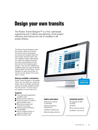
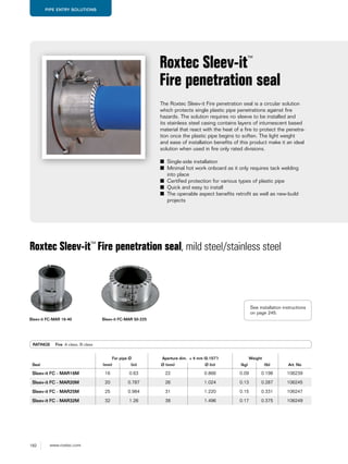
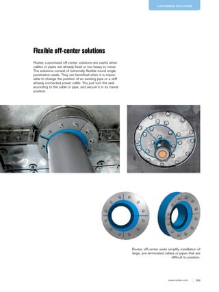
We Seal Your World™
CABLE & PIPE TRANSITS
FOR MARINE APPLICATIONS
M
ARINE
2 www.roxtec.com
3www.roxtec.com
Efficient solutions
Roxtec cable and pipe transits
ensure operational reliability by
providing certified protection
against fire, gas, water and dust.
The corrosion resistant and area
efficient seals help you reduce
vibration, noise, and overall
weight. They are also available in
EMC versions for electrical safety
and protection against electro-
magnetic interference and as
ATEX/IECEx certified products for
use in explosive atmospheres.
Upgrade – anytime
The Roxtec sealing system is
easy to use and quick to install.
The sealing modules are adapt-
able to cables and pipes of differ-
ent sizes and offer built-in spare
capacity for future needs and
upgrades. You can open up the
transits whenever you want – and
just add new cables or pipes.
Safe Blue Seal
There is a simple way of bringing peace and safety
to a ship, no matter if it is an advanced navy ship, an
offshore supply vessel or the world’s biggest luxury
cruise liner. Make sure you specify, design for and
install Roxtec cable and pipe transits – the blue seals
made for the Seven Seas.
ROXTEC IN ACTION 6
Application areas 8
Sealing solutions for any ship 12
First class performance 18
Focusing on sustainability 20
Roxtec Transit Designer 22
THE ROXTEC SEALING SYSTEM 24
System components 26
Roxtec modules
RM modules 27
CM modules 29
Wedges 32
Stayplates 35
Lubricant/Assembly gel 37
CABLE ENTRY SOLUTIONS 38
Regular frames and seals 39
S frame 40
SRC frame 47
SK frame 52
SBTB frame 54
SF frame 56
GHM frame 61
R frame 63
Sleeves for R frame 66
RS seal 69
Sleeves for RS seal 73
RS OMD seal 78
RX frame 81
RS X seal 81
Enclosure solutions 85
ComSeal LW 86
ComSeal 88
CF 8/CF 32 frames 91
KFO frame 94
C KFO frame 96
G frame 98
EMC SEALING SYSTEM 102
Electromagnetic compatibility 103
EMC sealing system selection guide 109
EMC modules
RM BG B, RM BG modules 110
RM ES B, RM ES modules 112
RM PE B, RM PE modules 115
CM BG B modules 118
CM ES modules 119
CM PE modules 120
EMC Wedge 121
EMC frame selection guide 123
Ground lug 123
EMC marking tool 123
Frames/seals for EMC applications 124
R EMC frame 125
RS EMC seals 127
ComSeal EMC 129
CF 8 EMC/CF 32 EMC frames/kits 131
Roxtec EMC installation – basic steps 133
PIPE ENTRY SOLUTIONS 134
Metal pipe solutions 137
RS seal 138
Sleeves for RS frame 142
RS OMD seal 147
R frame 150
Sleeves for R frame 153
SPM seal 156
RX frame 159
RS X seal 159
S frame 163
Plastic pipe solutions 170
RS PPS/S single-side seal 172
Sleeves for RS PPS/S seal 174
RS PPS back-to-back seal 176
Sleeves for RS PPS seal 179
SE PPS extension frame 180
Sleev-it Fire penetration seal 182
Sleev-it Waterproof penetration seal 185
Sleev-it Transition collar 188
Water-tightness after fire solutions 190
RS F+WT 191
RS PPS/S F+WT 192
RS PPS F+WT 194
Roxtec pipe seal selection guide 196
RETROFIT SOLUTIONS 200
CUSTOMIZED SOLUTIONS 206
CABLE AND PIPE MANAGEMENT 210
Cable straps 212
Roxtec installation tools 214
EASY INSTALLATION WITH ROXTEC 220
Installation instructions 221
Training and inspections 253
PRACTICAL USER GUIDELINES 264
Welding 266
Bolting 276
Insulation 283
Templates and holecut patterns 284
6 www.roxtec.com
ROXTEC IN ACTION
7www.roxtec.com
8 www.roxtec.com
EMC APPLICATION AREAS
Sensitive equipment ensuring
data, security and functionality
onboard.
Needs and requirements
■ EMC, electromagnetic
compatibility
■ Electromagnetic shielding
against EMI
PROPULSION ROOM
Propulsion machinery spaces.
Needs and requirements
■ Fire protection
■ Gas-tight
■ Watertight
■ EMI protection
■ Capacity to withstand
temperature changes
■ Vibration damping
■ Area efficient multi-cable
management
Roxtec SF EMCRoxtec SRC
Optional sealing solution: Optional sealing solution:
Discover some of the applications in the
marine industry where Roxtec cable and
pipe transits are used to protect life and
sensitive equipment. Approved by all major
classification societies, Roxtec transits
are recommended both for new build and
retrofit projects.
GAS-TIGHT AREA
Gas-tight seals ideal for
use in areas where there is
a need for maintaining the
pressure.
Needs and requirements
■ Firestop
■ Water barrier
■ Gas-tight
■ Pressure resistant
Roxtec S
Optional sealing solution:
9www.roxtec.com
SERVICE PIPES
Single or multiple pipes for
air compression and cooling;
plastic pipes for reduction of
overall weight.
Needs and requirements
■ Fire protection
■ Gas-tight
■ Watertight
■ Noise reduction
■ Vibration damping
ROOM PENETRATIONS IN
DECKS AND BULKHEADS
ABOVE THE WATERLINE
Cable and pipe penetrations
in decks and bulkheads
between fire zones.
Needs and requirements
■ Firestop
■ Gas-tight
■ Watertight
■ Multi-cable management
Roxtec Sleev-it™ Fire
penetration seal
Roxtec RS
Optional sealing solution: Optional sealing solution:
CABINS
Light-weight and versatile
solutions recommended both
for new build and retrofit
projects.
Needs and requirements
■ Gas-tight
■ Watertight
■ Easy installation
■ Minimal insulation
Roxtec ComSeal™
Optional sealing solution:
10 www.roxtec.com
OUTER LIGHTING
Round seals for single wires
through outer bulkheads for
external lighting installations.
Needs and requirements
■ Area efficient
■ Fire protection
■ Watertight
■ Adaptability to cables of
different sizes
WATER PIPES
Light-weight seals for steel
pipes and plastic pipes as well
as fire collars and steel-to-
plastic transition collars.
Needs and requirements
■ Fire protection
■ Gas-tight
■ Watertight
■ Vibration protection
■ Easy installation
■ Non-welding solutions
Roxtec RS PPSRoxtec RS
Optional sealing solution: Optional sealing solution:
Roxtec Sleev-it™ Watertight
penetration seal
CABIN SERVICE LOCKERS
Management and sealing
of service pipes and cables
connected to the cabin locker
area behind the cabin.
Needs and requirements
■ Firestop
■ Combination of steel and
plastic pipes
Optional sealing solution:
11www.roxtec.com
Roxtec S EMC
BRIDGE
OPERATION ROOM
EMC cable and pipe transits
developed to guarantee
electromagnetic shielding.
Needs and requirements
■ Fire-resistant
■ Watertight
■ Gas-tight
■ Electromagnetic shielding
■ Protection for sensitive
equipment
COMMON
OPERATION ROOM
Efficient solutions for EMC,
electromagnetic compatibility,
inside and around the opera-
tion room.
Needs and requirements
■ Equipment protection
■ Data security
■ High-precision operation
■ Electromagnetic shielding
Roxtec CF EMC
Optional sealing solution: Optional sealing solution:
ROOM PENETRATIONS
BELOW THE WATERLINE
Multiple cables penetrating
decks and bulkheads.
Needs and requirements
■ Fire-proof according to A-0
to A-60 marine fire rating
■ Watertight according to
class approval programs
■ Smoke protection
■ Pressure rated
■ Vibration damping
Roxtec S
Optional sealing solution:
12 www.roxtec.com
Sealing solutions for any ship
Shipbuilders and ship owners standardize with Roxtec
transits for cables, metal pipes and plastic pipes. Approved
for A class rated sections, the seals handle fire, water, gas
pressure, thermal bridges, and material fatigue in any kind
of vessel, from work boats to mega yachts.
13www.roxtec.com
With Roxtec, it is easy to add
cables, metal and plastic pipes
whenever it is time for new
attractions. Upgrades can be
performed while cruising – and
without risking structure or pas-
senger safety. This barrier against
fire and water holds down the
total cost of ownership.
Roxtec in the cabin
Roxtec seals are light-weight,
versatile and easy to install
solutions providing certified fire
protection. They prevent fire, gas
or water from entering the next
compartment. The seals are area
efficient and require minimal
welding and insulation.
Cruise liners
and ferries
14 www.roxtec.com
Reliability is key. Besides
water-tightness and blast load
durability, the Roxtec EMC
product line ensures protection
against electromagnetic threats
and prevents disclosure of
electronic signatures. Vibration
damping, area efficiency, and
plastic pipe solutions contrib-
ute to lower overall weight,
more space onboard and silent
operation. All components have
been tested to provide certified
protection.
Roxtec in the common
operation room
Roxtec has developed efficient
solutions for EMC inside and
around the operation room. The
cable and pipe transits ensure
electrical safety. Use Roxtec
transits to prevent EMI and
secure high-precision operation.
Navy ships
15www.roxtec.com
Ship owners specify Roxtec to
be able to operate their ships and
maintain their value for years.
Designers and installers all over
the world recognize that Roxtec
transits make it easy to upgrade
and even inspect ships in accor-
dance with new technical and
safety demands. For hazardous
areas, Roxtec provides ATEX/
IECEx certified seals.
Roxtec around the water
pipes
Roxtec offers light-weight seals
for steel pipes and plastic pipes
as well as fire collars and steel-
to-plastic transition collars – and
all of them are very easy to
install. Most Roxtec seals can be
installed horizontally or vertically
from one side – and there are
versions available that do not
require any welding.
Commercial
shipping
and supply
vessels
16 www.roxtec.com
Roxtec standard and customized
seals are used for everything
from high-precision bow thruster
systems to underwater opera-
tion equipment and cranes. They
protect against fire, gas, water
and vibration while keeping the
ship prepared for upgrades. This
extends the life cycle –
without increasing costs.
Gas-tight area
Roxtec solutions do not only act
as firestops and water barriers.
The seals include features such
as gas-tightness, making them
ideal for use in areas where there
is a need for maintaining the pres-
sure. If, for example, there is a
fire nearby and the atmosphere
is filled with explosive chemicals
and toxic substances, it is crucial
to be able to keep dangers out by
pressurizing the vessel’s interior.
Special
purpose ships
17www.roxtec.com
Roxtec seals give outstanding
possibilities to accommodate new
technologies. The ability to handle
plastic pipes of different sizes
helps reducing overall weight and
the risk of corrosion. Add also
the excellent sound and vibration
damping, which improves the total
yachting experience.
Outer lighting
Roxtec round seals for single
cables are perfect for use in outer
bulkheads when you want to
secure external lighting installa-
tions, for example on passenger
cabin balconies. The solutions are
neat and area efficient, and pro-
vide superior protection against
fire and water.
Yachts
18 www.roxtec.com
First class performance
Do you fear a fire onboard? Or water flooding from
one compartment to another? We can provide you
certified protection – thanks to our thoroughly tested
cable and pipe transits.
You can use the Roxtec sealing
system to seal all types of pene-
trating cables, steel pipes and
plastic pipes passing through decks
and bulkheads, in and between
different sections and constructions
such as machine rooms, storage
rooms, living compartments and
the bridge. You can also use it in
various types of control cabinets,
electrical enclosures and junction
boxes.
Certified for peace of mind
Our sealing solutions bring peace
of mind to your project, because
they have undergone hundreds
of registered tests and approvals
and received more than 250 cer-
tificates showing their excellent
performance and resistance to
hazards. Roxtec products are fire
tested and approved for use in
A, B and H class rated sections
according to IMO Res. A 754 (18)/
IMO FTP 2010 and SOLAS, and
tightness tested according to DNV
type approval program 8-471.19-1.
The Roxtec sealing system is also
approved according to different mil-
itary standards in various countries.
19www.roxtec.com
Eliminating risk factors
Roxtec seals ensure protection
against fire, water, gas, salt, and
dust. They can protect against
the risk of explosion, lightning
strikes, and noise. They also offer
solutions for bonding, grounding,
and EMC. The system is well
suited for sealing of hydraulic
pipes, since the rubber absorbs
vibrations. It is a high quality seal-
ing system designed to withstand
tough conditions.
■ A, H and jet-fire rated
■ Gas-tight
■ Watertight
■ Dust-tight
■ Corrosion protection
■ Vibration-proof
■ Noise reduction
■ Blast load protection
■ Hazardous locations
■ Electromagnetic shielding
■ Potential equalization
■ Lightning strike protection
■ Bonding and grounding
Safety awareness
Our process of developing
standard sealing products and
creating customized solutions
is supported by our procedures
for testing. We have a technical
center with an advanced test
laboratory in combination with
a fire laboratory, daily used for
R&D, indicative as well as third
party witnessed tests. Our type
approval certificates, issued by
the classification societies, are of
course issued on basis of tests
conducted at IMO recognized/
accredited test laboratories.
■ A and B class fire (standard,
fibrous)
■ H class fire (hydrocarbon,
oil-based)
■ Water pressure tests up to
6 bar
■ Gas pressure test up to 2.5 bar
■ Pull-out tests
■ Periodic cycling
■ Simulated IP rating tests
■ EMC testing
■ Vibration testing and analyzing
Verified by inspectors
Roxtec products are certified by all leading classification societies such as Lloyd's Register
of Shipping, American Bureau of Shipping, Bureau Veritas, DNV GL and Russian Maritime
Register of Shipping.
It is, however, important to remember that the certified protection provided by the Roxtec
sealing system depends on correct attachment to the structure by welding or bolting as well
as a correct installation procedure. Read more about this on pages 220 and 264 and on
www.roxtec.com.
20 www.roxtec.com
21www.roxtec.com
Roxtec International is certified
in accordance with the quality
and environmental standards ISO
9001 and ISO 14001. Among the
components we produce, you
find steel frames and vulcanized
rubber, but you can be sure that
no Roxtec labeled products con-
tain any dangerous materials. We
follow national and international
environmental legal requirements.
We respect environmental objec-
tives and ethical issues as well as
issues concerning chemicals and
law requirements such as RoHS
and REACH. We also handle
our waste correctly to save our
planet.
Focusing on sustainability
We do not just believe in safety. We also care about
the people, the nature and the oceans of our beautiful
blue planet. Therefore, we assure quality and minimize
our environmental impact.
22 www.roxtec.com
23www.roxtec.com
The Roxtec Transit Designer simpli-
fies product selection as well as
the entire process of designing,
purchasing and installing cable and
pipe transits. Its batch import with
auto validation feature helps design-
ers create and update thousands
of transits automatically and take
full control of their largest project
designs. They can also validate their
complete project by using the Roxtec
CAD symbols and the Roxtec Transit
Designer for easy incorporation of
transits into the design of the entire
ship or vessel.
Always available, everywhere
Roxtec Transit Designer is accessible
online. You can share your work with
project teams worldwide, and Roxtec
experts are always available through
the chat function. To start using it,
just register on www.roxtec.com.
Features
■ Free web-based application,
available online
■ Simple product selection
■ Copy and paste for cable or
pipe schedule inputs
■ Manufacturer-approved
engineering outputs
■ Improve project efficiency
and flexibility
■ Import multiple transits to
speed up design work
■ Reduce project risks
Design your own transits
The Roxtec Transit Designer™ is a free, web-based
engineering tool. It allows auto-planning, drives project
efficiency and reduces the risk of mistakes in all
project phases.
SIMPLE USER INPUT
Cable/pipe schedule
or estimates
Sealing/certification
requirements
Installation preferences
Material quality selection
APPROVED OUTPUT
2D drawings in DXF
and PDF
3D STEP
Bill of material in Excel
Installation instructions
GET STARTED ON
roxtec.com
24 www.roxtec.com
THE ROXTEC SEALING SYSTEM
25www.roxtec.com
THE ROXTEC SEALING SYSTEM
Superior flexibility
Roxtec sealing solutions for cables and pipes ensure
safety, efficiency and long-term operational reliability in
a wide range of marine projects worldwide.
Our invention for adaptability,
Multidiameter™, is a solution
based on rubber modules with
removable layers. It allows for a
perfect sealing, regardless of the
dimension of the cable or pipe.
This flexibility simplifies planning
and design, speeds up installation
work and reduces the need for
stock, material and logistics. It
also provides built-in spare capac-
ity for cost-efficient maintenance
and future upgrades.
Breaking innovation
The Roxtec solution has revo-
lutionized the design and the
process of cable routing and pipe
installation. Thanks to Roxtec
Multidiameter, each module can
handle a number of cable and
pipe sizes. It is also possible to
add extra capacity from the start.
Users can therefore perform their
tasks without knowing the size
or number of cables or pipes in
advance – which reduces engi-
neering hours.
Flexible components
The Roxtec sealing system is
a mechanical sealing solution
available for various applications,
including multiple as well as
single-cable and pipe penetra-
tions. In most Roxtec transits,
the sealing modules are inserted
around cables or pipes in frames
that are welded or bolted to the
structure. The frames are avail-
able in different shapes, materials
and sizes for different applica-
tions. The system is sealed with
a Roxtec Wedge or an integrated
compression unit.
Adaptable modules
The Roxtec system means very
few parts. With six basic Roxtec
module sizes, you can easily seal
cables and pipes from 4 mm to
99 mm in diameter in transits with
multiple openings. Standard ver-
sions of single penetration seals
handle cables or pipes with a
diameter of up to 580 mm. There
is also a range of modules with
different features, in order to
cover all your safety needs.
There is, for example, the EMC
product line. It provides efficient
solutions for bonding and ground-
ing of armored and shielded
cables as well as for electrical
safety in fully shielded environ-
ments.
THE ROXTEC SEALING SYSTEM
26 www.roxtec.com
*Seal – solution for single cable or pipe
Few parts to make a strong barrier
This is an overview showing how very few
components you need to put together a
complete Roxtec sealing solution. There
are rectangular and round seals available
as well as practical kit solutions.
Wedge
Frame
Wedge Clip
Stayplate
Lubricant
Frame
Seal*
Sleeve
Kit including all
components
Modules
RECTANGULAR SOLUTIONS
ROUND SOLUTIONS
KIT SOLUTIONS
THE ROXTEC SEALING SYSTEM
27www.roxtec.com
THE ROXTEC SEALING SYSTEM
Roxtec RM modules
Roxtec modules in product group RM are based on 60 mm
(2.362") standard depth and used for sealing of cables and pipes
in walls, floors, bulkheads and decks. Modules in group CM are
based on depths of 15-40 mm (0.591"-1.575"). Areas of use are
entry sealing of cables and smaller hoses in cabinets and enclo-
sures. Both groups, RM and CM, are available for the EMC and
Ex application areas.
■ Roxtec RM modules with Multidiameter™ are adaptable
to cables and pipes with OD 3.0-99.0 mm (0.118"-3.898")
■ Roxtec CM modules with Multidiameter™ are adaptable
to cables and pipes with OD 3.5-34.5 mm (0.138"-1.358")
■ When used with a solid core the module functions as a
spare module for future capacity needs.
Roxtec modules
RM 60 woc RM 80 woc
RM 120 woc
RM 15 RM 15w40* RM 20 RM 20w40* RM 30 RM 40
RM 40 10-32 RM 60 RM 60 24-54
RM 90 woc
28 www.roxtec.com
THE ROXTEC SEALING SYSTEM
Module
Number of
cables/pipes
For cable/pipe diameter External dim. (mm)
HxW (D=60 mm)
Weight (max)
Art. NoØa-Øb (mm) Øa-Øb (in) (kg) (lb)
WITH CORE
RM 15 1 0+3.0-11.0 0+0.118-0.433 15x15 0.02 0.044 RM00100151000
RM 15w40* 3 0+3.5-10.5 0+0.138-0.413 15x40 0.05 0.110 RM00115401000
RM 20 1 0+4.0-14.5 0+0.157-0.571 20x20 0.04 0.088 RM00100201000
RM 20w40* 2 0+3.5-16.5 0+0.138-0.650 20x40 0.07 0.154 RM00120401000
RM 30 1 0+10.0-25.0 0+0.394-0.984 30x30 0.08 0.176 RM00100301000
RM 40 1 0+21.5-34.5 0+0.846-1.358 40x40 0.14 0.309 RM00100401000
RM 40 10-32 1 0+9.5-32.5 0+0.374-1.280 40x40 0.14 0.309 RM00140101000
RM 60 1 0+28.0-54.0 0+1.102-2.126 60x60 0.33 0.728 RM00100601000
RM 60 24-54 1 0+24.0-54.0 0+0.945-2.126 60x60 0.33 0.728 RM00160201000
WITHOUT CORE
RM 60 woc 1 28.0-54.0 1.102-2.126 60x60 0.26 0.573 RM00000601000
RM 80 woc 1 48.0-71.0 1.890-2.795 80x80 0.44 0.970 5RM0000000534
RM 90 woc 1 48.0-71.0 1.890-2.795 90x90 0.56 1.253 RM00000901000
RM 120 woc 1 67.5-99.0 2.657-3.898 120x120 0.94 2.072 RM00001201000
* Smart tip: Whenever possible we recommend choosing twin or triplet modules like RM 20w40 or RM 15w40.
Benefits are higher area efficiency per frame opening, quicker installation and improved cost-effectiveness.
Roxtec RM modules
Roxtec solid compensation module kits for SRC frames
RM 20/0 RC RM 40/0 RC
Module
No. of modules/kit
External dim. (mm)
HxW (D=60 mm)
Weight per kit
Art. No(kg) (lb)
RM 20/0 RC 4 20x20 0.13 0.287 RMC0300201000
RM 40/0 RC 4 40x40 0.30 0.661 RMC0300401000
29www.roxtec.com
THE ROXTEC SEALING SYSTEM
Roxtec RM solid compensation modules
Module
External dim. (mm)
HxW (D=60 mm)
Weight (max)
Art. No(kg) (lb)
RM 5/0x24 5x120 0.06 0.126 RM00305241000
RM 10/0x12 10x120 0.12 0.256 RM00310121000
RM 15/0 15x15 0.02 0.049 RM00300151000
RM 20/0 20x20 0.04 0.086 RM00300201000
RM 30/0 30x30 0.08 0.179 RM00300301000
RM 40/0 40x40 0.15 0.320 RM00300401000
RM 60/0 60x60 0.33 0.719 RM00300601000
RM 5/0x24 RM 10/0x12RM 30/0
Smart tip: Consider using an RM module rather than a solid module. A Roxtec RM module installed with a solid centre
core serves the same purpose as a traditional solid module, but it also provides spare capacity for future installations.
CM 20CM 15w40* CM 20w40* CM 30 CM 30w40 CM 40 10-32CM 40
Roxtec CM modules
Module
Number of
cables/pipes
For cable/pipe diameter External dim. (mm)
HxW (D=30 mm)
Weight (max)
Art. NoØa-Øb (mm) Øa-Øb (in) (kg) (lb)
CM 15w40* 3 0+ 3.5-10.5 0+ 0.138-0.413 15x40 0.03 0.055 C000115401000
CM 20 1 0+ 4.0-14.5 0+ 0.157-0.571 20x20 0.02 0.044 C000100201000
CM 20w40* 2 0+ 3.5-16.5 0+ 0.138-0.650 20x40 0.04 0.077 C000120401000
CM 30 1 0+ 10.0-25.0 0+ 0.394-0.984 30x30 0.04 0.088 C000100301000
CM 30w40 1 0+ 10.0-25.0 0+ 0.394-0.984 30x40 0.06 0.121 C000130401000
CM 40 1 0+21.5-34.5 0+ 0.846-1.358 40x40 0.07 0.135 5CM0000008983
CM 40 10-32 1 0+ 9.5-32.5 0+ 0.374-1.280 40x40 0.07 0.135 C000140101000
* Smart tip: Whenever possible we recommend choosing twin or triplet modules like CM 20w40 or CM 15w40.
Benefits are higher area efficiency per frame opening, quicker installation and improved cost-effectiveness.
30 www.roxtec.com
THE ROXTEC SEALING SYSTEM
D
W
H
Øb
Øa
D
H
W
Øb
Øa
D
H
W
Øb
Øa
Roxtec RM modules, technical information
RM modules Solid corner compensation
module for SRC frames
H
W
R1
D
D
W
c
H
c
R2
Note: All dimensions
are nominal values
* Smart tip: Consider using a CM module rather than a solid module. A Roxtec CM module installed with a solid centre core serves the
same purpose as a traditional solid module, but it also provides spare capacity for future installations.
CM 5w40/0* CM 10w40/0*
Roxtec CM solid compensation modules
Module
External dim. (mm)
HxW (D=30 mm)
Weight (max)
Art. No(kg) (lb)
CM 5w40/0 5x40 0.01 0.022 C000305401000
CM 10w40/0 10x40 0.02 0.044 C000310401000
Pos (mm) (in)
R1 R 20 R 0.787
R2 R 40 R 1.575
c 20 0.787
D 60 2.362
Pos
Øa Min. cable/pipe diameter
Øb Max. cable/pipe diameter
D 60 mm 2.362"
Note: All dimensions
are nominal values
31www.roxtec.com
THE ROXTEC SEALING SYSTEM
Roxtec RM solid compensation modules, technical information
D
D
HH
W
W
W
H
D
Note: All dimensions are nominal values
Roxtec CM modules, technical information
CM modules CM solid compensation modules
D
W
H
Øb
Øa
D
D
H
W
Øb
Øa
H
W
Øb
Øa
H
WD
Pos
Øa Min. cable/pipe diameter
Øb Max. cable/pipe diameter
D 30 mm 1.181" Note: All dimensions
are nominal values
Pos (mm) (in)
D 30 1.181
Pos (mm) (in)
D 60 2.362
Note: All dimensions
are nominal values
32 www.roxtec.com
THE ROXTEC SEALING SYSTEM
Roxtec Wedges are used in frames with a rectangular packing
space without built-in compression to compress and seal the
installation of cables, pipes, modules and stayplates.
■ The Roxtec Wedge is for use with Group RM frames
and components
■ The Roxtec C Wedge is for use with Group CM frames
and components
Roxtec Wedges
Wedge
External dimensions Weight
Art. NoW (mm) W (in) (kg) (lb)
Wedge kit galv* (wedge) 120 (wedge) 4.724 1.5 3.307 AWK0001201018
Wedge 120 galv 120 4.724 0.8 1.764 ARW0001201018
Wedge 60 galv 60 2.362 0.4 0.882 ARW0000601018
Wedge kit/parts, galvanized
* The Wedge kit includes one Roxtec Wedge 120, five stayplates, one Wedge Clip, one lubricant and installation instructions.
Wedge kit galv Wedge 120 galv Wedge 60 galv
33www.roxtec.com
THE ROXTEC SEALING SYSTEM
Wedge
External dimensions Weight
Art. NoW (mm) W (in) (kg) (lb)
Wedge kit AISI 316* (wedge) 120 (wedge) 4.724 1.5 3.307 AWK0001201021
Wedge 120 AISI 316 120 4.724 0.8 1.764 ARW0001201021
Wedge 60 AISI 316 60 2.362 0.4 0.882 ARW0000601021
Wedge kit/parts, acid-proof stainless steel
* The Wedge kit includes one Roxtec Wedge 120, five stayplates, one Wedge Clip, one lubricant and installation instructions.
Wedge kit AISI 316 Wedge 120 AISI 316 Wedge 60 AISI 316
Wedge
External dimensions Weight
Art. NoW (mm) W (in) (kg) (lb)
C Wedge kit galv* 120 4.724 0.65 1.443 AWK2001201018
C Wedge 120 galv 120 4.724 0.40 0.882 CRW0001201018
C Wedge kit/parts, galvanized
* The Wedge kit includes one Roxtec C Wedge 120, six C stayplates, one lubricant and installation instructions.
C Wedge kit galv C Wedge 120 galv
34 www.roxtec.com
THE ROXTEC SEALING SYSTEM
Wedge
External dimensions Weight
Art. NoW (mm) W (in) (kg) (lb)
C Wedge kit AISI 316* 120 4.724 0.65 1.443 AWK2001201021
C Wedge 120 AISI 316 120 4.724 0.40 0.882 5crw000011340
C Wedge kit/parts, acid-proof stainless steel
* The Wedge kit includes one Roxtec C Wedge 120, six C stayplates, one lubricant and installation instructions.
C Wedge kit AISI 316 C Wedge 120 AISI 316
Wedge, technical information
Note: All dimensions are nominal values
W
Wedge 60
c
h2
d2
Uncompressed
d3
h1
Compressed
d4
h3
Uncompressed
W
C Wedge 120
c
d1
h1
Compressed
W
Wedge 120
c
C Wedge
Wedge
Pos (mm) (in)
d1 109 4.291
d2 130 5.118
d3 61 2.402
d4 70 2.756
h1 48 1.890
h2 29 1.142
h3 32 1.260
c SW 13 SW 0.512
35www.roxtec.com
THE ROXTEC SEALING SYSTEM
Roxtec Stayplates provide mechanical anchorage for the
modules in order to keep them in the frame and protect against
blow-outs. To be inserted between rows of modules in frames
with a rectangular packing space and no built-in compression.
■ The Roxtec Stayplate is for use with Group RM frames
and components
■ The Roxtec C Stayplate is for use with Group CM frames
and components
Roxtec Stayplates
Stayplate
Fits packing space Weight
Art. NoW (mm) W (in) (kg) (lb)
Stayplate 120 galv 120 4.724 0.1 0.243 ASP0001200018
Stayplate 60 galv 60 2.362 0.06 0.132 ASP0000600018
Stayplate 120 AISI 316 120 4.724 0.1 0.243 ASP0001200021
Stayplate 60 AISI 316 60 2.362 0.06 0.132 ASP0000600021
Stayplate 120 ALU 120 4.724 0.04 0.088 ASP0001200031
Stayplate 60 ALU 60 2.362 0.02 0.044 ASP0000600031
Stayplate
Stayplate
Fits packing space Weight
Art. NoW (mm) W (in) (kg) (lb)
C Stayplate 120 galv 120 4.724 0.02 0.051 ASP2001200018
C Stayplate 120 AISI 316 120 4.724 0.02 0.051 ASP3001200021
C Stayplate
C Stayplate 120 galv
Stayplate 120 galv Stayplate 60 galv Stayplate 120 AISI 316 Stayplate 60 AISI 316 Stayplate 120 ALU Stayplate 60 ALU
C Stayplate 120 AISI 316
36 www.roxtec.com
THE ROXTEC SEALING SYSTEM
Stayplate, technical information
galv Galvanized
AISI 316 Acid-proof stainless steel
ALU Aluminum
d
D
t
H f
W1
w1
c
Stayplate 120 Pos (mm) (in)
c 4 0.157
d 62 2.499
e 26 1.024
f 86 3.386
t 0.5 0.020
D 82 3.228
H 5 0.197
W1 119 4.685
w1 127 5.000
W2 59 2.323
w2 67 2.638
e
W2
w2
Stayplate 60
d
D
t
H
c
Note: All dimensions are nominal values
37www.roxtec.com
THE ROXTEC SEALING SYSTEM
The lubricant is natural tallow used to lubricate the sealing
modules, the Roxtec Wedge and the inside of the frame.
This provides correct compression and a secure seal.
The assembly gel is intended for Roxtec ComSeal™ LW
and Roxtec ComSeal™.
Roxtec Lubricant/
Roxtec Assembly Gel
Roxtec Lubricant
Lubricant 10 ml Lubricant 25 ml
Assembly Gel 30 ml Assembly Gel Bag 10 ml
Roxtec Assembly Gel
Lubricant Art. No
Lubricant 10 ml ALT0000001000
Lubricant 25 ml ALT0000003000
Assembly Gel Art. No
Assembly Gel 30 ml ALT0000004000
Assembly Gel Bag 10 ml ALT0000005000
38 www.roxtec.com
CABLE ENTRY SOLUTIONS
39www.roxtec.com
CABLE ENTRY SOLUTIONS
Regular frames and seals
Roxtec regular cable transits for decks, bulkheads,
floors and walls are successfully used in the ship-
building industry since 1990.
Roxtec regular frames are avail-
able in different designs and mate-
rials, such as mild steel, stainless
steel and aluminum, and they can
be attached either through bolting,
welding or fitting into sleeves. The
depth of the frames is normally 60
mm (2.362"), and they are filled
with standard RM modules of the
same depth. Together the mod-
ules cover a cable diameter range
of 3 to 99 mm (0.118"-3.898"). To
complete the installation and seal
the transit, you also need lubri-
cant, stayplates and a wedge.
The seals are also available for
use in EMC and Ex applications.
40 www.roxtec.com
CABLE ENTRY SOLUTIONS
Roxtec S frame is a metal frame available with a single opening,
or in combinations with several openings in width and/or height.
■ For use with Group RM components
■ Attachment by welding
Roxtec S frame
Frame
Frame
openings
Packing space
(mm)
External dimensions (D=60 mm) Weight
Art. NoHxW (mm) HxW (in) (kg) (lb)
S 1x1 primed 1 60 x 60 121 x 80 4.764 x 3.150 1.6 3.527 SS01000000112
S 2x1 primed 1 60 x 120 121 x 141 4.764 x 5.551 2.2 4.938 S002000000112
S 2x2 primed 2 60 x 120 121 x 271 4.764 x 10.669 3.9 8.488 S002000000212
S 2x3 primed 3 60 x 120 121 x 402 4.764 x 15.827 5.5 12.037 S002000000312
S 2x4 primed 4 60 x 120 121 x 532 4.764 x 20.945 7.1 15.609 S002000000412
S 2x5 primed 5 60 x 120 121 x 663 4.764 x 26.102 8.7 19.158 S002000000512
S 2x6 primed 6 60 x 120 121 x 793 4.764 x 31.220 10.3 22.707 S002000000612
S 3x1 primed 1 120 x 60 180 x 80 7.087 x 3.150 2.3 5.071 SS03000000112
S frame, primed mild steel
RATINGS Fire: A class, H class Water pressure: 4 bar Gas pressure: 2.5 bar
S 6x1 primed
See parts needed for a complete solution on page 26.
See installation instructions on page 222.
See practical user guidelines on page 264.
Remove primer from the inside of the frame to ensure
good conductivity in EMC applications.
For information about other frame combinations, or for
openable versions of this frame, please contact your local
Roxtec supplier or e-mail: info@roxtec.com
41www.roxtec.com
CABLE ENTRY SOLUTIONS
Frame
Frame
openings
Packing space
(mm)
External dimensions (D=60 mm) Weight
Art. NoHxW (mm) HxW (in) (kg) (lb)
S 4x1 primed 1 120 x 120 180 x 141 7.087 x 5.551 2.8 6.151 S004000000112
S 4x2 primed 2 120 x 120 180 x 271 7.087 x 10.669 4.7 10.318 S004000000212
S 4x3 primed 3 120 x 120 180 x 402 7.087 x 15.827 6.6 14.484 S004000000312
S 4x4 primed 4 120 x 120 180 x 532 7.087 x 20.945 8.5 18.629 S004000000412
S 4x5 primed 5 120 x 120 180 x 663 7.087 x 26.102 10.3 22.796 S004000000512
S 4x6 primed 6 120 x 120 180 x 793 7.087 x 31.220 12.2 26.962 S004000000612
S 4x7 primed 7 120 x 120 180 x 924 7.087 x 36.378 14.1 31.129 S004000000712
S 4x8 primed 8 120 x 120 180 x 1054 7.087 x 41.496 16.0 35.296 S004000000812
S 4x9 primed 9 120 x 120 180 x 1185 7.087 x 46.654 17.9 39.440 S004000000912
S 4+4x1 primed 2 120 x 120 349 x 141 13.740 x 5.551 5.0 11.067 S004400000112
S 4+4x2 primed 4 120 x 120 359 x 271 14.134 x 10.669 9.5 20.878 S004400000212
S 4+4x3 primed 6 120 x 120 359 x 402 14.134 x 15.827 13.5 29.321 S004400000312
S 4+4x4 primed 8 120 x 120 359 x 532 14.134 x 20.945 17.1 37.743 S004400000412
S 4+4x5 primed 10 120 x 120 359 x 663 14.134 x 26.102 21.0 46.186 S004400000512
S 4+4x6 primed 12 120 x 120 359 x 793 14.134 x 31.220 24.8 54.630 S004400000612
S 4+4x7 primed 14 120 x 120 359 x 924 14.134 x 36.378 28.6 63.096 S004400000712
S 4+4x8 primed 16 120 x 120 359 x 1054 14.134 x 41.496 32.6 71.539 S004400000812
S 4+4+4x1 primed 3 120 x 120 519 x 141 20.433 x 5.551 6.6 14.550 S004440000112
S 4+4+4x2 primed 6 120 x 120 539 x 271 21.220 x 10.669 14.2 31.305 S004440000212
S 4+4+4x3 primed 9 120 x 120 539 x 402 21.220 x 15.827 19.9 43.872 S004440000312
S 4+4+4x4 primed 12 120 x 120 539 x 532 21.220 x 20.945 26.2 57.761 S004440000412
S 4+4+4x5 primed 15 120 x 120 539 x 663 21.220 x 26.102 31.3 69.004 S004440000512
S 4+4+4x6 primed 18 120 x 120 539 x 793 21.220 x 31.220 37.0 81.570 S004440000612
S 5x1 primed 1 180 x 60 238 x 80 9.370 x 3.150 2.8 6.173 SS05000000112
S 6x1 primed 1 180 x 120 238 x 141 9.370 x 5.551 3.3 7.363 S006000000112
S 6x2 primed 2 180 x 120 238 x 271 9.370 x 10.669 5.5 12.147 S006000000212
S 6x3 primed 3 180 x 120 238 x 402 9.370 x 15.827 7.7 16.909 S006000000312
S 6x4 primed 4 180 x 120 238 x 532 9.370 x 20.945 9.8 21.671 S006000000412
S 6x5 primed 5 180 x 120 238 x 663 9.370 x 26.102 12.0 26.455 S006000000512
S 6x6 primed 6 180 x 120 238 x 793 9.370 x 31.220 14.2 31.217 S006000000612
S 6x7 primed 7 180 x 120 238 x 924 9.370 x 36.378 16.3 35.979 S006000000712
S 6x8 primed 8 180 x 120 238 x 1054 9.370 x 41.496 18.5 40.763 S006000000812
S 6x9 primed 9 180 x 120 238 x 1185 9.370 x 46.654 20.7 45.525 S006000000912
S 6+6x1 primed 2 180 x 120 466 x 141 18.346 x 5.551 6.1 13.492 S006600000112
S 6+6x2 primed 4 180 x 120 476 x 271 18.740 x 10.669 11.1 24.537 S006600000212
S 6+6x3 primed 6 180 x 120 476 x 402 18.740 x 15.827 15.5 34.171 S006600000312
S 6+6x4 primed 8 180 x 120 476 x 532 18.740 x 20.945 19.9 43.827 S006600000412
S 6+6x5 primed 10 180 x 120 476 x 663 18.740 x 26.102 24.3 53.506 S006600000512
S frame, primed mild steel
42 www.roxtec.com
CABLE ENTRY SOLUTIONS
S frame, primed mild steel
Frame
Frame
openings
Packing space
(mm)
External dimensions (D=60 mm) Weight
Art. NoHxW (mm) HxW (in) (kg) (lb)
S 6+6x6 primed 12 180 x 120 476 x 793 18.740 x 31.220 28.6 63.140 S006600000612
S 6+6x7 primed 14 180 x 120 476 x 924 18.740 x 36.378 33.0 72.796 S006600000712
S 6+6x8 primed 16 180 x 120 476 x 1054 18.740 x 41.496 37.4 82.474 S006600000812
S 6+6x9 primed 18 180 x 120 476 x 1185 18.740 x 46.654 41.8 92.108 S006600000912
S 6+6x10 primed 20 180 x 120 476 x 1315 18.740 x 51.772 46.2 101.764 S006600001012
S 6+6+6x1 primed 3 180 x 120 694 x 141 27.323 x 5.551 8.2 18.078 S006660000112
S 7x1 primed 1 240 x 60 298 x 80 11.732 x 3.150 3.3 7.363 SS07000000112
S 8x1 primed 1 240 x 120 298 x 141 11.732 x 5.551 3.9 8.620 S008000000112
S 8x2 primed 2 240 x 120 298 x 271 11.732 x 10.669 6.1 13.382 S008000000212
S 8x3 primed 3 240 x 120 298 x 402 11.732 x 15.827 8.2 18.144 S008000000312
S 8x4 primed 4 240 x 120 298 x 532 11.732 x 20.945 10.4 22.928 S008000000412
S 8x5 primed 5 240 x 120 298 x 663 11.732 x 26.102 12.6 27.690 S008000000512
S 8x6 primed 6 240 x 120 298 x 793 11.732 x 31.220 14.7 32.452 S008000000612
S 8+8x1 primed 2 240 x 120 586 x 141 23.071 x 5.551 7.3 16.005 S008800000112
S 8+8x2 primed 4 240 x 120 596 x 271 23.465 x 10.669 12.3 27.006 S008800000212
S 8+8x3 primed 6 240 x 120 596 x 402 23.465 x 15.827 16.6 36.640 S008800000312
S 8+8x4 primed 8 240 x 120 596 x 532 23.465 x 20.945 21.0 46.341 S008800000412
S 8+8x5 primed 10 240 x 120 596 x 663 23.465 x 26.102 25.4 55.975 S008800000512
S 8+8x6 primed 12 240 x 120 596 x 793 23.465 x 31.220 29.8 65.609 S008800000612
S 8+8x7 primed 14 240 x 120 596 x 924 23.465 x 36.378 34.2 75.309 S008800000712
S 8+8x8 primed 16 240 x 120 596 x 1054 23.465 x 41.496 38.5 84.943 S008800000812
S 8+8x9 primed 18 240 x 120 596 x 1185 23.465 x 46.654 42.9 94.577 S008800000912
S 8+8x10 primed 20 240 x 120 596 x 1315 23.465 x 51.772 47.3 104.278 S008800001012
S 8+8+8x1 primed 3 240 x 120 874 x 141 34.409 x 5.551 9.9 21.826 S008880000112
43www.roxtec.com
CABLE ENTRY SOLUTIONS
S frame, acid-proof stainless steel
RATINGS Fire: A class, H class Water pressure: 4 bar Gas pressure: 2.5 bar
Frame
Frame
openings
Packing space
(mm)
External dimensions (D=60 mm) Weight
Art. NoHxW (mm) HxW (in) (kg) (lb)
S 2x1 AISI 316 1 60 x 120 121 x 141 4.764 x 5.551 2.2 4.938 S002000000121
S 2x2 AISI 316 2 60 x 120 121 x 271 4.764 x 10.669 3.9 8.488 S002000000221
S 2x3 AISI 316 3 60 x 120 121 x 402 4.764 x 15.827 5.5 12.037 S002000000321
S 2x4 AISI 316 4 60 x 120 121 x 532 4.764 x 20.945 7.1 15.609 S002000000421
S 2x5 AISI 316 5 60 x 120 121 x 663 4.764 x 26.102 8.7 19.158 S002000000521
S 2x6 AISI 316 6 60 x 120 121 x 793 4.764 x 31.220 10.3 22.707 S002000000621
S 4x1 AISI 316 1 120 x 120 180 x 141 7.087 x 5.551 2.8 6.151 S004000000121
S 4x2 AISI 316 2 120 x 120 180 x 271 7.087 x 10.669 4.7 10.318 S004000000221
S 4x3 AISI 316 3 120 x 120 180 x 402 7.087 x 15.827 6.6 14.484 S004000000321
S 4x4 AISI 316 4 120 x 120 180 x 532 7.087 x 20.945 8.5 18.629 S004000000421
S 4x5 AISI 316 5 120 x 120 180 x 663 7.087 x 26.102 10.3 22.796 S004000000521
S 4x6 AISI 316 6 120 x 120 180 x 793 7.087 x 31.220 12.2 26.962 S004000000621
S 4+4x1 AISI 316 2 120 x 120 349 x 141 13.740 x 5.551 5.0 11.067 S004400000121
S 4+4+4x1 AISI 316 3 120 x 120 519 x 141 20.433 x 5.551 6.6 14.550 S004440000121
S 6x1 AISI 316 1 180 x 120 238 x 141 9.370 x 5.551 3.3 7.363 S006000000121
S 6x2 AISI 316 2 180 x 120 238 x 271 9.370 x 10.669 5.5 12.147 S006000000221
S 6x3 AISI 316 3 180 x 120 238 x 402 9.370 x 15.827 7.7 16.909 S006000000321
S 6x4 AISI 316 4 180 x 120 238 x 532 9.370 x 20.945 9.8 21.671 S006000000421
S 6x5 AISI 316 5 180 x 120 238 x 663 9.370 x 26.102 12.0 26.455 S006000000521
S 6x6 AISI 316 6 180 x 120 238 x 793 9.370 x 31.220 14.2 31.217 S006000000621
S 6+6x1 AISI 316 2 180 x 120 466 x 141 18.346 x 5.551 6.1 13.492 S006600000121
S 6+6x2 AISI 316 4 180 x 120 476 x 271 18.740 x 10.669 11.1 24.537 S006600000221
S 6+6x3 AISI 316 6 180 x 120 476 x 402 18.740 x 15.827 15.5 34.171 S006600000321
S 6+6x4 AISI 316 8 180 x 120 476 x 532 18.740 x 20.945 19.9 43.872 S006600000421
S 6+6x5 AISI 316 10 180 x 120 476 x 663 18.740 x 26.102 24.3 53.506 S006600000521
S 6+6x6 AISI 316 12 180 x 120 476 x 793 18.740 x 31.220 28.6 63.140 S006600000621
S 6x1 AISI 316
See parts needed for a complete solution on page 26.
See installation instructions on page 222.
See practical user guidelines on page 264.
For information about other frame combinations, or for
openable versions of this frame, please contact your local
Roxtec supplier or e-mail: info@roxtec.com
44 www.roxtec.com
CABLE ENTRY SOLUTIONS
Frame
Frame
openings
Packing space
(mm)
External dimensions (D=60 mm) Weight
Art. NoHxW (mm) HxW (in) (kg) (lb)
S 8x1 AISI 316 1 240 x 120 298 x 141 11.732 x 5.551 3.9 8.620 S008000000121
S 8x2 AISI 316 2 240 x 120 298 x 271 11.732 x 10.669 6.1 13.382 S008000000221
S 8x3 AISI 316 3 240 x 120 298 x 402 11.732 x 15.827 8.2 18.144 S008000000321
S 8x4 AISI 316 4 240 x 120 298 x 532 11.732 x 20.945 10.4 22.928 S008000000421
S 8x5 AISI 316 5 240 x 120 298 x 663 11.732 x 26.102 12.6 27.690 S008000000521
S 8x6 AISI 316 6 240 x 120 298 x 793 11.732 x 31.220 14.7 32.452 S008000000621
S 8+8x1 AISI 316 2 240 x 120 586 x 141 23.071 x 5.551 7.3 16.005 S008800000121
S 8+8+8x1 AISI 316 3 240 x 120 874 x 141 34.409 x 5.551 9.9 21.826 S008880000121
S frame, acid-proof stainless steel
S frame, aluminum
RATINGS Fire: A class, H class Water pressure: 4 bar Gas pressure: 2.5 bar
Frame
Frame
openings
Packing space
(mm)
External dimensions (D=60 mm) Weight
Art. NoHxW (mm) HxW (in) (kg) (lb)
S 2x1 ALU 1 60 x 120 121 x 141 4.764 x 5.551 0.8 1.698 S002000000131
S 2x2 ALU 2 60 x 120 121 x 271 4.764 x 10.669 1.3 2.910 S002000000231
S 2x3 ALU 3 60 x 120 121 x 402 4.764 x 15.827 1.9 4.145 S002000000331
S 2x4 ALU 4 60 x 120 121 x 532 4.764 x 20.945 2.4 5.357 S002000000431
S 2x5 ALU 5 60 x 120 121 x 663 4.764 x 26.102 3.0 6.592 S002000000531
S 2x6 ALU 6 60 x 120 121 x 793 4.764 x 31.220 3.5 7.804 S002000000631
S 2+2x1 ALU 2 60 x 120 232 x 141 9.134 x 5.551 1.3 2.965 S002200000131
S 2+2+2x1 ALU 3 60 x 120 343 x 141 13.504 x 5.551 1.7 3.748 S002220000131
S 4x1 ALU 1 120 x 120 180 x 141 7.087 x 5.551 1.0 2.116 S004000000131
S 4x2 ALU 2 120 x 120 180 x 271 7.087 x 10.669 1.6 3.549 S004000000231
S 4x3 ALU 3 120 x 120 180 x 402 7.087 x 15.827 2.3 4.982 S004000000331
S 6x1 ALU
See parts needed for a complete solution on page 26.
See installation instructions on page 222.
See practical user guidelines on page 264.
For information about other frame combinations, or for
openable versions of this frame, please contact your local
Roxtec supplier or e-mail: info@roxtec.com
45www.roxtec.com
CABLE ENTRY SOLUTIONS
Frame
Frame
openings
Packing space
(mm)
External dimensions (D=60 mm) Weight
Art. NoHxW (mm) HxW (in) (kg) (lb)
S 4x4 ALU 4 120 x 120 180 x 532 7.087 x 20.945 2.9 6.415 S004000000431
S 4x5 ALU 5 120 x 120 180 x 663 7.087 x 26.102 3.6 7.848 S004000000531
S 4x6 ALU 6 120 x 120 180 x 793 7.087 x 31.220 4.2 9.281 S004000000631
S 4+4x1 ALU 2 120 x 120 349 x 141 13.740 x 5.551 1.7 3.762 S004400000131
S 4+4x2 ALU 4 120 x 120 359 x 271 14.134 x 10.669 3.2 7.099 S004400000231
S 4+4x3 ALU 6 120 x 120 359 x 402 14.134 x 15.827 4.5 9.965 S004400000331
S 4+4x4 ALU 8 120 x 120 359 x 532 14.134 x 20.495 5.8 12.831 S004400000431
S 4+4+4x1 ALU 3 120 x 120 519 x 141 20.433 x 5.551 2.3 5.071 S004440000131
S 6x1 ALU 1 180 x 120 238 x 141 9.370 x 5.551 1.2 2.535 S006000000131
S 6x2 ALU 2 180 x 120 238 x 271 9.370 x 10.669 1.9 4.167 S006000000231
S 6x3 ALU 3 180 x 120 238 x 402 9.370 x 15.827 2.6 5.820 S006000000331
S 6x4 ALU 4 180 x 120 238 x 532 9.370 x 20.495 3.4 7.452 S006000000431
S 6x5 ALU 5 180 x 120 238 x 663 9.370 x 26.102 4.1 9.083 S006000000531
S 6x6 ALU 6 180 x 120 238 x 793 9.370 x 31.220 4.9 10.736 S006000000631
S 6+6x1 ALU 2 180 x 120 466 x 141 18.346 x 5.551 2.1 4.630 S006600000131
S 6+6x2 ALU 4 180 x 120 476 x 271 18.740 x 10.669 3.8 8.333 S006600000231
S 6+6x3 ALU 6 180 x 120 476 x 402 18.740 x 15.827 5.3 11.640 S006600000331
S 6+6x4 ALU 8 180 x 120 476 x 532 18.740 x 20.495 6.8 14.903 S006600000431
S 6+6x5 ALU 10 180 x 120 476 x 663 18.740 x 26.102 8.2 18.166 S006600000531
S 6+6x6 ALU 12 180 x 120 476 x 793 18.740 x 31.220 9.7 21.473 S006600000631
S 6+6+6x1 ALU 3 180 x 120 694 x 141 27.323 x 5.551 2.8 6.173 S006660000131
S 8x1 ALU 1 240 x 120 298 x 141 11.732 x 5.551 1.3 2.954 S008000000131
S 8x2 ALU 2 240 x 120 298 x 271 11.732 x 10.669 2.2 4.806 S008000000231
S 8x3 ALU 3 240 x 120 298 x 402 11.732 x 15.872 3.0 6.658 S008000000331
S 8x4 ALU 4 240 x 120 298 x 532 11.732 x 20.495 3.9 8.532 S008000000431
S 8x5 ALU 5 240 x 120 298 x 663 11.732 x 26.102 4.7 10.385 S008000000531
S 8x6 ALU 6 240 x 120 298 x 793 11.732 x 31.220 5.6 12.236 S008000000631
S 8+8x1 ALU 2 240 x 120 586 x 141 23.071 x 5.551 2.5 5.467 S008800000131
S 8+8+8x1 ALU 3 240 x 120 874 x 141 34.409 x 5.551 3.4 7.496 S008880000131
S frame, aluminum
46 www.roxtec.com
CABLE ENTRY SOLUTIONS
S frame, technical information
S Zx1 S ZxN
S Z+Zx1 S Z+ZxN S Z+Z+Zx1
A-A
A-A
A-A
A-A
A
H
A R
ht1
t1 w
W
D H
h w
W
A
A
t1
H
w
W
A
A
t1
t2
W
h
H
h
w
A-A
A
A
H
h
W
w
A
At1
t1
Pos (mm) (in)
h H - 20 H - 0.787
w W - 20 W - 0.787
D 60 2.362
t1 10 0.394
t2 20 0.787
R R 10 R 0.394 Note: All dimensions are nominal values
Z = Frame size
N = Number of horizontal openings
47www.roxtec.com
CABLE ENTRY SOLUTIONS
The Roxtec SRC frame is a metal frame intended for load bear-
ing structures. Designed with rounded corners to reduce stress
concentration and the risk of cracks around the frame. Available
in two standard versions, SRC r20 and SRC r40.
■ For use with Group RM components
■ Attachment by welding
Roxtec SRC frame
Frame
Frame
openings
Packing space*
(mm)
External dimensions Weight
Art. NoHxW (mm) HxW (in) (kg) (lb)
SRC 2x1 r20 primed 1 60 x 120 121 x 141 4.764 x 5.551 2.2 4.938 SRC2000020112
SRC 2x2 r20 primed 2 60 x 120 121 x 271 4.764 x 10.669 3.9 8.488 SRC2000020212
SRC 2x3 r20 primed 3 60 x 120 121 x 402 4.764 x 15.827 5.5 12.037 SRC2000020312
SRC 2x4 r20 primed 4 60 x 120 121 x 532 4.764 x 20.945 7.1 15.609 SRC2000020412
SRC 2x5 r20 primed 5 60 x 120 121 x 663 4.764 x 26.102 8.7 19.158 SRC2000020512
SRC 2x6 r20 primed 6 60 x 120 121 x 793 4.764 x 31.220 10.3 22.707 SRC2000020612
SRC 4x1 r20 primed 1 120 x 120 180 x 141 7.077 x 5.551 2.8 6.151 SRC4000020112
SRC 4x2 r20 primed 2 120 x 120 180 x 271 7.077 x 10.669 4.7 10.318 SRC4000020212
SRC frame, corner radius 20 mm, primed mild steel
RATINGS Fire: A class, H class Water pressure: 4 bar Gas pressure: 2.5 bar
SRC 6x1 r20 primed
See parts needed for a complete solution on page 26.
See installation instructions on page 226.
See practical user guidelines on page 264.
For information about other frame combinations,
please contact your local Roxtec supplier or e-mail:
info@roxtec.com
48 www.roxtec.com
CABLE ENTRY SOLUTIONS
Frame
Frame
openings
Packing space*
(mm)
External dimensions Weight
Art. NoHxW (mm) HxW (in) (kg) (lb)
SRC 4x3 r20 primed 3 120 x 120 180 x 402 7.077 x 15.827 6.6 14.484 SRC4000020312
SRC 4x4 r20 primed 4 120 x 120 180 x 532 7.077 x 20.945 8.5 18.629 SRC4000020412
SRC 4x5 r20 primed 5 120 x 120 180 x 663 7.077 x 26.102 10.3 22.796 SRC4000020512
SRC 4x6 r20 primed 6 120 x 120 180 x 793 7.077 x 31.220 12.2 26.962 SRC4000020612
SRC 4x7 r20 primed 7 120 x 120 180 x 924 7.077 x 36.378 14.1 31.129 SRC4000020712
SRC 4x8 r20 primed 8 120 x 120 180 x1054 7.077 x 41.496 16.0 35.296 SRC4000020812
SRC 4x9 r20 primed 9 120 x 120 180 x 1185 7.077 x 46.654 17.9 39.440 SRC4000020912
SRC 6x1 r20 primed 1 180 x 120 238 x 141 9.370 x 5.551 3.3 7.363 SRC6000020112
SRC 6x2 r20 primed 2 180 x 120 238 x 271 9.370 x 10.669 5.5 12.147 SRC6000020212
SRC 6x3 r20 primed 3 180 x 120 238 x 402 9.370 x 15.827 7.7 16.909 SRC6000020312
SRC 6x4 r20 primed 4 180 x 120 238 x 532 9.370 x 20.945 9.8 21.671 SRC6000020412
SRC 6x5 r20 primed 5 180 x 120 238 x 663 9.370 x 26.102 12.0 26.455 SRC6000020512
SRC 6x6 r20 primed 6 180 x 120 238 x 793 9.370 x 31.220 14.2 31.217 SRC6000020612
SRC 6x7 r20 primed 7 180 x 120 238 x 924 9.370 x 36.378 16.3 35.979 SRC6000020712
SRC 6x8 r20 primed 8 180 x 120 238 x 1054 9.370 x 41.496 18.5 40.763 SRC6000020812
SRC 6x9 r20 primed 9 180 x 120 238 x 1185 9.370 x 45.654 20.8 45.525 SRC6000020912
SRC 8x1 r20 primed 1 240 x 120 298 x 141 11.732 x 5.551 3.9 8.620 SRC8000020112
SRC 8x2 r20 primed 2 240 x 120 298 x 271 11.732 x 10.669 6.1 13.382 SRC8000020212
SRC 8x3 r20 primed 3 240 x 120 298 x 402 11.732 x 15.827 8.2 18.144 SRC8000020312
SRC 8x4 r20 primed 4 240 x 120 298 x 532 11.732 x 20.945 10.4 22.928 SRC8000020412
SRC 8x5 r20 primed 5 240 x 120 298 x 663 11.732 x 26.102 12.6 27.690 SRC8000020512
SRC 8x6 r20 primed 6 240 x 120 298 x 793 11.732 x 31.220 14.7 32.452 SRC8000020612
SRC frame, corner radius 20 mm, primed mild steel
* Please note that the corner radius reduces actual packing space for SRC frames.
49www.roxtec.com
CABLE ENTRY SOLUTIONS
SRC Zx1 SRC ZxN
A
w
A-A
A-A
t
H
A A
t
A
W
D
h
H
h
w
W
R1
R2
t
Z = Frame size
N = Number of horizontal openings
SRC frame, corner radius 20 mm, technical information
Pos (mm) (in)
h H - 20 H - 0.787
w W - 20 W - 0.787
D 60 2.362
t 10 0.394
R1 R 20 (4x) R 0.787 (4x)
R2 R 30 (4x) R 1.181 (4x)
Note: All dimensions are nominal values
Wedge 120 Wedge 120Wedge 120
RM 20/0 RC
Packing space
SRC 6x1 SRC 6x2
50 www.roxtec.com
CABLE ENTRY SOLUTIONS
Frame
Frame
openings
Packing space
(mm)
External dimensions Weight
Art. NoHxW (mm) HxW (in) (kg) (lb)
SRC 4x1 r40 primed 1 120 x 120 180 x 141 7.077 x 5.551 2.8 6.151 SRC4000040112
SRC 4x2 r40 primed 2 120 x 120 180 x 271 7.077 x 10.669 4.7 10.318 SRC4000040212
SRC 4x3 r40 primed 3 120 x 120 180 x 402 7.077 x 15.827 6.6 14.484 SRC4000040312
SRC 4x4 r40 primed 4 120 x 120 180 x 532 7.077 x 20.945 8.5 18.629 SRC4000040412
SRC 4x5 r40 primed 5 120 x 120 180 x 663 7.077 x 26.102 10.3 22.796 SRC4000040512
SRC 4x6 r40 primed 6 120 x 120 180 x 793 7.077 x 31.220 12.2 26.962 SRC4000040612
SRC 4x7 r40 primed 7 120 x 120 180 x 924 7.077 x 36.378 14.1 31.129 SRC4000040712
SRC 4x8 r40 primed 8 120 x 120 180 x 1054 7.077 x 41.496 16.0 35.296 SRC4000040812
SRC 4x9 r40 primed 9 120 x 120 180 x 1185 7.077 x 46.654 17.9 39.440 SRC4000040912
SRC 6x1 r40 primed 1 180 x 120 238 x 141 9.370 x 5.551 3.3 7.363 SRC6000040112
SRC 6x2 r40 primed 2 180 x 120 238 x 271 9.370 x 10.669 5.5 12.147 SRC6000040212
SRC 6x3 r40 primed 3 180 x 120 238 x 402 9.370 x 15.827 7.7 16.909 SRC6000040312
SRC 6x4 r40 primed 4 180 x 120 238 x 532 9.370 x 20.945 9.8 21.671 SRC6000040412
SRC 6x5 r40 primed 5 180 x 120 238 x 663 9.370 x 26.102 12.0 26.455 SRC6000040512
SRC 6x6 r40 primed 6 180 x 120 238 x 793 9.370 x 31.220 14.2 31.217 SRC6000040612
SRC 6x7 r40 primed 7 180 x 120 238 x 924 9.370 x 36.378 16.3 35.979 SRC6000040712
SRC 6x8 r40 primed 8 180 x 120 238 x 1054 9.370 x 41.496 18.5 40.763 SRC6000040812
SRC 6x9 r40 primed 9 180 x 120 238 x 1185 9.370 x 45.654 20.8 45.525 SRC6000040912
SRC 8x1 r40 primed 1 240 x 120 298 x 141 11.732 x 5.551 3.9 8.620 SRC8000040112
SRC 8x2 r40 primed 2 240 x 120 298 x 271 11.732 x 10.669 6.1 13.382 SRC8000040212
SRC 8x3 r40 primed 3 240 x 120 298 x 402 11.732 x 15.827 8.2 18.144 SRC8000040312
SRC 8x4 r40 primed 4 240 x 120 298 x 532 11.732 x 20.945 10.4 22.928 SRC8000040412
SRC 8x5 r40 primed 5 240 x 120 298 x 663 11.732 x 26.102 12.6 27.690 SRC8000040512
SRC 8x6 r40 primed 6 240 x 120 298 x 793 11.732 x 31.220 14.7 32.452 SRC8000040612
SRC frame, corner radius 40 mm, primed mild steel
RATINGS Fire: A class, H class Water pressure: 4 bar Gas pressure: 2.5 bar
SRC 6x1 r40 primed
* Please note that the corner radius reduces actual packing space for SRC frames.
See parts needed for a complete solution on page 26.
See installation instructions on page 226.
See practical user guidelines on page 264.
For information about other frame combinations,
please contact your local Roxtec supplier or e-mail:
info@roxtec.com
51www.roxtec.com
CABLE ENTRY SOLUTIONS
Z = Frame size
N = Number of horizontal openings
SRC Zx1 SRC ZxN
A
w
A-A
t
H
A A
t
A
W
D
h
H
h
w
W
R1
R2
t A-A
Pos (mm) (in)
h H - 20 H - 0.787
w W - 20 W - 0.787
D 60 2.362
t 10 0.394
R1 R 40 (4x) R 1.575 (4x)
R2 R 50 (4x) R 1.969 (4x)
SRC frame, corner radius 40 mm, technical information
Note: All dimensions are nominal values
Wedge 120 Wedge 120Wedge 120
Packing space
RM 40/0 RC
SRC 6x1 SRC 6x2
52 www.roxtec.com
CABLE ENTRY SOLUTIONS
Roxtec SK frame is an S frame with extended depth. This
enables, among other benefits, angled installations and/or
increased distance between the packing space and the steel
section.
■ For use with Group RM components
■ Attachment by welding
Roxtec SK frame
SK frame, primed mild steel
RATINGS Fire: A class, H class Water pressure: 4 bar Gas pressure: 2.5 bar
Frame
Frame
openings
Packing space
(mm)
External dimensions (D=100 mm) Weight
Art. NoHxW (mm) HxW (in) (kg) (lb)
SK 2x1 primed 1 60 x 120 121 x 141 4.764 x 5.551 4.4 9.612 5SK0000002074
SK 2x2 primed 2 60 x 120 121 x 271 4.764 x 10.669 7.1 15.675 5SK0000003137
SK 2x3 primed 3 60 x 120 121 x 402 4.764 x 15.827 9.9 21.738 5SK0000003138
SK 2x4 primed 4 60 x 120 121 x 532 4.764 x 20.945 12.6 27.800 5SK0000003148
SK 4x1 primed 1 120 x 120 180 x 141 7.087 x 5.551 5.4 11.905 5SK0000004398
SK 4x2 primed 2 120 x 120 180 x 271 7.087 x 10.669 8.4 18.585 5SK0000003139
SK 4x3 primed 3 120 x 120 180 x 402 7.087 x 15.827 11.5 25.243 5SK0000003140
SK 4x4 primed 4 120 x 120 180 x 532 7.087 x 20.945 14.5 31.923 5SK0000003141
SK 6x1 primed
See parts needed for a complete solution on page 26.
See installation instructions on page 222.
See practical user guidelines on page 264.
Remove primer from the inside of the frame to ensure
good conductivity in EMC applications.
For information about other frame combinations,
please contact your local Roxtec supplier or e-mail:
info@roxtec.com
53www.roxtec.com
CABLE ENTRY SOLUTIONS
SK frame, primed mild steel
Frame
Frame
openings
Packing space
(mm)
External dimensions (D=100 mm) Weight
Art. NoHxW (mm) HxW (in) (kg) (lb)
SK 6x1 primed 1 180 x 120 238 x 141 9.370 x 5.551 5.2 11.464 5SK0000004397
SK 6x2 primed 2 180 x 120 238 x 271 9.370 x 10.669 8.2 18.298 5SK0000004504
SK 6x3 primed 3 180 x 120 238 x 402 9.370 x 15.827 11 24.251 5SK0000004399
SK 6x4 primed 4 180 x 120 238 x 532 9.370 x 20.945 14.3 31.526 5SK0000004400
SK 8x1 primed 1 240 x 120 298 x 141 11.732 x 5.551 7.5 16.535 5SK0000004915
SK 8x2 primed 2 240 x 120 298 x 271 11.732 x 10.669 12.4 27.315 5SK0000003145
SK 8x3 primed 3 240 x 120 298 x 402 11.732 x 15.827 17.3 38.118 5SK0000003146
SK 8x4 primed 4 240 x 120 298 x 532 11.732 x 20.945 22.2 48.899 5SK0000003147
SK frame, technical information
Note: All dimensions are nominal values
SK Zx1 SK ZxN
A-AA-A
A
H
A R
ht1
t1 w
W
D
H
h
w
W
A
A
t1
Pos (mm) (in)
h H - 20 H - 0.787
w W - 20 W - 0.787
D 100 3.937
d 60 2.362
t1 10 0.394
R R 10 R 0.394
Z = Frame size
N = Number of horizontal openings
D
d d
54 www.roxtec.com
CABLE ENTRY SOLUTIONS
The Roxtec SBTB frame is a metal frame with two packing
spaces behind each other (back-to-back). The SBTB frame
is designed to meet high levels of fire protection and for
easy verification of pressure tightness after installation.
■ For use with two sets of Group RM components
■ Pressure test pipe available
■ Attachment by welding
Roxtec SBTB frame
SBTB frame, primed mild steel
RATINGS Fire: A class, H class Water pressure: 4 bar Gas pressure: 2.5 bar
Frame
Frame
openings
Packing space
(mm)
External dimensions (D=200 mm) Weight
Art. NoHxW (mm) HxW (in) (kg) (lb)
SBTB 2x1 primed 1 60 x 120 121 x 141 4.764 x 5.531 7.2 15.939 5SBT000003961
SBTB 2x2 primed 2 60 x 120 121 x 271 4.764 x 10.669 12.0 26.389 SBTB020000212
SBTB 2x3 primed 3 60 x 120 121 x 402 4.764 x 15.827 16.7 36.839 SBTB020000312
SBTB 2x4 primed 4 60 x 120 121 x 532 4.764 x 20.945 21.5 47.289 SBTB020000412
SBTB 4x1 primed 1 120 x 120 180 x 141 7.087 x 5.531 8.9 19.709 5S00000004392
SBTB 4x2 primed 2 120 x 120 180 x 271 7.087 x 10.669 14.2 31.372 SBTB040000212
SBTB 4x3 primed 3 120 x 120 180 x 402 7.087 x 15.807 19.5 43.034 SBTB040000312
SBTB 4x4 primed 4 120 x 120 180 x 532 7.087 x 20.945 24.8 54.697 SBTB040000412
SBTB 4x5 primed 5 120 x 120 180 x 663 7.087 x 26.083 30.1 66.359 SBTB040000512
SBTB 4x6 primed 6 120 x 120 180 x 793 7.087 x 31.220 35.4 78.022 SBTB040000612
SBTB 6x1 primed
See parts needed for a complete solution on page 26.
See installation instructions on page 222.
See practical user guidelines on page 264.
Remove primer from the inside of the frame to ensure
good conductivity in EMC applications.
For information about other frame combinations,
please contact your local Roxtec supplier or e-mail:
info@roxtec.com
55www.roxtec.com
CABLE ENTRY SOLUTIONS
Frame
Frame
openings
Packing space
(mm)
External dimensions (D=200 mm) Weight
Art. NoHxW (mm) HxW (in) (kg) (lb)
SBTB 6x1 primed 1 180 x 120 238 x 141 9.370 x 5.531 10.6 23.479 5S00000004391
SBTB 6x2 primed 2 180 x 120 238 x 271 9.370 x 10.669 16.5 36.354 5S00000004503
SBTB 6x3 primed 3 180 x 120 238 x 402 9.370 x 15.807 22.3 49.229 5S00000004393
SBTB 6x4 primed 4 180 x 120 238 x 532 9.370 x 20.945 28.2 62.104 5S00000004394
SBTB 6x5 primed 5 180 x 120 238 x 663 9.370 x 26.083 34.0 74.979 5S00000004528
SBTB 6x6 primed 6 180 x 120 238 x 793 9.370 x 31.220 39.9 87.854 5S00000004500
SBTB 8x1 primed 1 240 x 120 298 x 141 11.732 x 5.531 12.4 27.337 SBTB080000112
SBTB 8x2 primed 2 240 x 120 298 x 271 11.732 x 10.669 18.8 41.469 SBTB080000212
SBTB 8x3 primed 3 240 x 120 298 x 402 11.732 x 15.807 25.2 55.579 SBTB080000312
SBTB 8x4 primed 4 240 x 120 298 x 532 11.732 x 20.945 31.6 69.710 SBTB080000412
SBTB frame, primed mild steel
SBTB frame, technical information
Note: All dimensions are nominal values
SBTB Zx1 SBTB ZxN
A-AA-A
A
H
A R
ht
t w
W
D
H
h
w
W
A
A
t
Pos (mm) (in)
h H - 20 H - 0.787
w W - 20 W - 0.787
D 200 7.874
d 60 2.362
t 10 0.394
R R 10 R 0.394
Z = Frame size
N = Number of horizontal openings
D
d d dd
56 www.roxtec.com
CABLE ENTRY SOLUTIONS
Roxtec SF frame is a metal frame with flange. Available with
a single opening, or in combinations with several openings in
width and/or height.
■ For use with Group RM components
■ Attachment by welding or bolting
Roxtec SF frame
SF frame, primed mild steel
RATINGS Fire: A class, H class Water pressure: 4 bar Gas pressure: 2.5 bar
Frame
Frame
openings
Packing space
(mm)
External dimensions (D=60 mm) Weight
Art. NoHxW (mm) HxW (in) (kg) (lb)
SF 2x1 primed 1 60 x 120 241 x 261 9.488 x 10.276 6.0 13.184 SFF2000000112
SF 2x2 primed 2 60 x 120 241 x 391 9.488 x 15.394 9.0 19.775 SFF2000000212
SF 2x3 primed 3 60 x 120 241 x 522 9.488 x 20.551 12.0 26.345 SFF2000000312
SF 2x4 primed 4 60 x 120 241 x 652 9.488 x 25.669 14.9 32.937 SFF2000000412
SF 2x5 primed 5 60 x 120 241 x 783 9.488 x 30.827 17.9 39.528 SFF2000000512
SF 2x6 primed 6 60 x 120 241 x 913 9.488 x 35.945 20.9 46.098 SFF2000000612
SF 4x1 primed 1 120 x 120 300 x 261 11.811 x 10.276 7.1 15.675 SFF4000000112
SF 4x2 primed 2 120 x 120 300 x 391 11.811 x 15.394 10.4 22.862 SFF4000000212
SF 4x3 primed 3 120 x 120 300 x 522 11.811 x 20.551 13.6 30.049 SFF4000000312
SF 4x4 primed 4 120 x 120 300 x 652 11.811 x 25.669 16.9 37.236 SFF4000000412
SF 6x1 primed
See parts needed for a complete solution on page 26.
See installation instructions on page 222.
See practical user guidelines on page 264.
Remove primer from the inside of the frame to ensure
good conductivity in EMC applications.
For information about other frame combinations, or for
openable versions of this frame, please contact your local
Roxtec supplier or e-mail: info@roxtec.com
57www.roxtec.com
CABLE ENTRY SOLUTIONS
Frame
Frame
openings
Packing space
(mm)
External dimensions (D=60 mm) Weight
Art. NoHxW (mm) HxW (in) (kg) (lb)
SF 4x5 primed 5 120 x 120 300 x 783 11.811 x 30.827 20.2 44.423 SFF4000000512
SF 4x6 primed 6 120 x 120 300 x 913 11.811 x 35.945 23.4 51.632 SFF4000000612
SF 4+4x1 primed 2 120 x 120 469 x 261 18.465 x 10.276 10.9 24.118 SFF4400000112
SF 4+4+4x1 primed 3 120 x 120 639 x 261 25.157 x 10.276 14.8 32.540 SFF4440000112
SF 6x1 primed 1 180 x 120 358 x 261 14.095 x 10.276 8.2 18.144 SFF6000000112
SF 6x2 primed 2 180 x 120 358 x 391 14.095 x 15.394 11.8 25.948 SFF6000000212
SF 6x3 primed 3 180 x 120 358 x 522 14.095 x 20.551 15.3 33.752 SFF6000000312
SF 6x4 primed 4 180 x 120 358 x 652 14.095 x 25.669 18.8 41.557 SFF6000000412
SF 6x5 primed 5 180 x 120 358 x 783 14.095 x 30.827 22.4 49.339 SFF6000000512
SF 6x6 primed 6 180 x 120 358 x 913 14.095 x 35.945 25.9 57.143 SFF6000000612
SF 6+6x1 primed 2 180 x 120 586 x 261 23.071 x 10.276 13.1 28.968 SFF6600000112
SF 6+6x2 primed 4 180 x 120 596 x 391 23.465 x 15.394 19.6 43.320 SFF6600000212
SF 6+6x3 primed 6 180 x 120 596 x 522 23.465 x 20.551 25.4 56.107 SFF6600000312
SF 6+6x4 primed 8 180 x 120 596 x 652 23.465 x 25.669 31.2 68.872 SFF6600000412
SF 6+6x5 primed 10 180 x 120 596 x 783 23.465 x 30.827 37.0 81.636 SFF6600000512
SF 6+6x6 primed 12 180 x 120 596 x 913 23.465 x 35.945 42.8 94.423 SFF6600000612
SF 6+6x7 primed 14 180 x 120 596 x 1044 23.465 x 41.102 48.6 107.188 SFF6600000712
SF 6+6x8 primed 16 180 x 120 596 x 1174 23.465 x 46.220 54.4 119.974 SFF6600000812
SF 6+6x9 primed 18 180 x 120 596 x 1305 23.465 x 51.378 60.2 132.739 SFF6600000912
SF 6+6x10 primed 20 180 x 120 596 x 1435 23.465 x 56.496 66.0 145.504 SFF6600001012
SF 6+6+6x1 primed 3 180 x 120 814 x 261 32.047 x 10.276 18.1 39.991 SFF6660000112
SF 8x1 primed 1 240 x 120 418 x 261 16.457 x 10.276 9.4 20.701 SFF8000000112
SF 8x2 primed 2 240 x 120 418 x 391 16.457 x 15.394 13.2 29.123 SFF8000000212
SF 8x3 primed 3 240 x 120 418 x 522 16.457 x 20.551 17.0 37.544 SFF8000000312
SF 8x4 primed 4 240 x 120 418 x 652 16.457 x 25.669 20.8 45.966 SFF8000000412
SF 8x5 primed 5 240 x 120 418 x 783 16.457 x 30.827 24.7 54.387 SFF8000000512
SF 8x6 primed 6 240 x 120 418 x 913 16.457 x 35.945 28.5 62.809 SFF8000000612
SF 8+8x1 primed 2 240 x 120 706 x 261 27.795 x 10.276 15.5 34.171 SFF8800000112
SF 8+8x2 primed 4 240 x 120 716 x 391 28.189 x 15.394 22.6 49.758 SFF8800000212
SF 8+8x3 primed 6 240 x 120 716 x 522 28.189 x 20.551 28.9 63.779 SFF8800000312
SF 8+8x4 primed 8 240 x 120 716 x 652 28.189 x 25.669 35.3 77.800 SFF8800000412
SF 8+8x5 primed 10 240 x 120 716 x 783 28.189 x 30.827 41.6 91.822 SFF8800000512
SF 8+8x6 primed 12 240 x 120 716 x 913 28.189 x 35.945 48.0 105.843 SFF8800000612
SF 8+8x7 primed 14 240 x 120 716 x 1044 28.189 x 41.102 54.4 119.864 SFF8800000712
SF 8+8x8 primed 16 240 x 120 716 x 1174 28.189 x 46.220 60.7 133.885 SFF8800000812
SF 8+8x9 primed 18 240 x 120 716 x 1305 28.189 x 51.378 67.1 147.907 SFF8800000912
SF 8+8x10 primed 20 240 x 120 716 x 1435 28.189 x 56.496 73.4 161.928 SFF8800001012
SF 8+8+8x1 primed 3 240 x 120 944 x 261 37.165 x 10.276 21.6 47.619 SFF8880000112
SF frame, primed mild steel
58 www.roxtec.com
CABLE ENTRY SOLUTIONS
SF frame, acid-proof stainless steel
RATINGS Fire: A class, H class Water pressure: 4 bar Gas pressure: 2.5 bar
Frame
Frame
openings
Packing space
(mm)
External dimensions (D=60 mm) Weight
Art. NoHxW (mm) HxW (in) (kg) (lb)
SF 2x1 AISI 316 1 60 x 120 241 x 261 9.488 x 10.276 6.0 13.184 SFF2000000121
SF 4x1 AISI 316 1 120 x 120 300 x 261 11.811 x 10.276 7.1 15.675 SFF4000000121
SF 4x2 AISI 316 2 120 x 120 300 x 391 11.811 x 15.394 10.4 22.862 SFF4000000221
SF 4x3 AISI 316 3 120 x 120 300 x 522 11.811 x 20.551 13.6 30.049 SFF4000000321
SF 4x4 AISI 316 4 120 x 120 300 x 652 11.811 x 25.669 16.9 37.236 SFF4000000421
SF 6x1 AISI 316 1 180 x 120 358 x 261 14.095 x 10.276 8.2 18.144 SFF6000000121
SF 6x2 AISI 316 2 180 x 120 358 x 391 14.095 x 15.394 11.8 25.948 SFF6000000221
SF 6x3 AISI 316 3 180 x 120 358 x 522 14.095 x 20.551 15.3 33.752 SFF6000000321
SF 6x4 AISI 316 4 180 x 120 358 x 652 14.095 x 25.669 18.8 41.557 SFF6000000421
SF 8x1 AISI 316 1 240 x 120 418 x 261 16.457 x 10.276 9.4 20.701 SFF8000000121
SF 8x2 AISI 316 2 240 x 120 418 x 391 16.457 x 15.394 13.2 29.123 SFF8000000221
SF 8x3 AISI 316 3 240 x 120 418 x 522 16.457 x 20.551 17.0 37.544 SFF8000000321
SF 8x4 AISI 316 4 240 x 120 418 x 652 16.457 x 25.669 20.8 45.966 SFF8000000421
SF 6x1 AISI 316
See parts needed for a complete solution on page 26.
See installation instructions on page 222.
See practical user guidelines on page 264.
For information about other frame combinations, or for
openable versions of this frame, please contact your local
Roxtec supplier or e-mail: info@roxtec.com
59www.roxtec.com
CABLE ENTRY SOLUTIONS
SF frame, aluminum
RATINGS Fire: A class, H class Water pressure: 4 bar Gas pressure: 2.5 bar
Frame
Frame
openings
Packing space
(mm)
External dimensions (D=60 mm) Weight
Art. NoHxW (mm) HxW (in) (kg) (lb)
SF 2x1 ALU 1 60 x 120 241 x 261 9.488 x 10.276 2.1 4.541 SFF2000000131
SF 4x1 ALU 1 120 x 120 300 x 261 11.811 x 10.276 2.4 5.379 SFF4000000131
SF 4x2 ALU 2 120 x 120 300 x 391 11.811 x 15.394 3.6 7.870 SFF4000000231
SF 4x3 ALU 3 120 x 120 300 x 522 11.811 x 20.551 4.7 10.340 SFF4000000331
SF 4x4 ALU 4 120 x 120 300 x 652 11.811 x 25.669 5.8 12.809 SFF4000000431
SF 6x1 ALU 1 180 x 120 358 x 261 14.095 x 10.276 3.3 7.187 SFF6000000131
SF 6x2 ALU 2 180 x 120 358 x 391 14.095 x 15.394 4.6 10.229 SFF6000000231
SF 6x3 ALU 3 180 x 120 358 x 522 14.095 x 20.551 6.0 13.250 SFF6000000331
SF 6x4 ALU 4 180 x 120 358 x 652 14.095 x 25.669 7.4 16.292 SFF6000000431
SF 8x1 ALU 1 240 x 120 418 x 261 16.457 x 10.276 3.7 8.157 SFF8000000131
SF 8x2 ALU 2 240 x 120 418 x 391 16.457 x 15.394 5.2 11.398 SFF8000000231
SF 8x3 ALU 3 240 x 120 418 x 522 16.457 x 20.551 6.6 14.661 SFF8000000331
SF 8x4 ALU 4 240 x 120 418 x 652 16.457 x 25.669 8.1 17.901 SFF8000000431
SF 6x1 ALU
See parts needed for a complete solution on page 26.
See installation instructions on page 222.
See practical user guidelines on page 264.
For information about other frame combinations, or for
openable versions of this frame, please contact your local
Roxtec supplier or e-mail: info@roxtec.com
60 www.roxtec.com
CABLE ENTRY SOLUTIONS
SF frame, technical information
Pos (mm) (in)
h H - 120 H - 4.724
w W -120 W - 4.724
D 60 2.362
f 60 2.362
t1 10 0.394
t2 3 0.118
t3 20 0.787
H
SF Zx1 SF ZxN
SF Z+Zx1 SF Z+ZxN SF Z+Z+Zx1
t1 t1
t1
hf
f
A
wf f
W
A
A-A
t1
D
t2 t2
H
h
A
A
t1
w
W
H
h
H
h
w
W
w
W
w
W
A
A
A-A
A-A A-A A-A
H
h
t1
t1
t1
t3
A
A
A
A
t1
t1
Note: All dimensions are nominal values
Z = Frame size
N = Number of horizontal openings
t2 t2
t2
t1 t1 t1
f f f
f
f
f
t1
t1
t1
t1t1t1
61www.roxtec.com
CABLE ENTRY SOLUTIONS
The Roxtec GHM frame is designed for installation through
bolting where welding is not suitable. The frame is sealed
onto the structure by use of the TSL sealing strip.
■ For use with Group RM components
■ Attachment by bolting
■ Drilled according to standardized hole pattern
Roxtec GHM frame
GHM frame, primed mild steel
RATINGS Fire: A class Water pressure: 3 bar Gas pressure: 1.5 bar
Frame
Frame
openings
Packing space
(mm)
External dimensions (D=60 mm) Weight
Art. NoHxW (mm) HxW (in) (kg) (lb)
GHM 2x1 primed 1 60 x 120 233 x 253 9.173 x 9.961 3.4 7.562 GHM2000000112
GHM 2x2 primed 2 60 x 120 233 x 383 9.173 x 15.079 5.4 11.905 GHM2000000212
GHM 2x3 primed 3 60 x 120 233 x 514 9.173 x 20.236 7.4 16.218 GHM2000000312
GHM 4x1 primed 1 120 x 120 292 x 253 11.496 x 9.961 4.1 9.039 GHM4000000112
GHM 4x2 primed 2 120 x 120 292 x 383 11.496 x 15.079 6.3 13.977 GHM4000000212
GHM 4x3 primed 3 120 x 120 292 x 514 11.496 x 20.236 8.6 18.938 GHM4000000312
GHM 6x1 primed 1 180 x 120 350 x 253 13.780 x 13.961 4.8 10.516 GHM6000000112
GHM 6x2 primed 2 180 x 120 350 x 383 13.780 x 15.079 7.3 16.072 GHM6000000212
GHM 6x3 primed 3 180 x 120 350 x 514 13.780 x 20.236 9.8 21.627 GHM6000000312
GHM 6x1 primed
See parts needed for a complete solution on page 26.
See installation instructions on page 222.
See practical user guidelines on page 264.
Remove primer from the inside of the frame to ensure
good conductivity in EMC applications.
For information about other frame combinations,
please contact your local Roxtec supplier or e-mail:
info@roxtec.com
62 www.roxtec.com
CABLE ENTRY SOLUTIONS
GHM frame, technical information
c
Y(Sx)
c
X(Tx)
e
Note: All dimensions are nominal values
X(Tx) Y(Sx)
X (mm) X (in) T Y (mm) Y (in) S
GHM 2x1 101.3 3.988 2 91.5 3.602 2
GHM 2x2 111 4.370 3 91.5 3.602 2
GHM 2x3 92.7 3.650 5 91.5 3.602 2
GHM 4x1 101.3 3.988 2 80.5 3.169 3
GHM 4x2 111 4.370 3 80.5 3.169 3
GHM 4x3 92.7 3.650 5 80.5 3.169 3
GHM 6x1 101.3 3.988 2 75 2.953 4
GHM 6x2 111 4.370 3 75 2.953 4
GHM 6x3 92.7 3.650 5 75 2.953 4
Hole pattern
G ZxN
H
h2 A
A
t2
w2
W A-A
f2
f2 D
t1
t4
A-A
D
t1
t4
H
h2
w2
W
f2
f2
A
A
t1 t1
t1
t1
G Zx1
Z = Frame size
N = Number of horizontal openings
Pos (mm) (in)
h2 H - 120 H - 4.724
w2 W -120 W - 4.724
D 60 2.362
f2 60 2.362
t1 6 0.263
t2 10 0.394
t3 12 0.394
t4 3 0.118
e 10 0.394
c 35 1.378
63www.roxtec.com
CABLE ENTRY SOLUTIONS
The Roxtec R is a round expansion frame with a square
packing space for cables and modules. Compression is
integrated in the frame. Allows installation around existing
cables.
■ For use with RM modules
■ Attachment by expansion in sleeves
■ Sleeves are available
Roxtec R frame
R frame, galvanized fittings
RATINGS Fire: A class, H class Water pressure: 4 bar Gas pressure: 2.5 bar
R 100 galv R 125 galv R 127 galv R 150 galv R 200 galv
Frame
Packing space
(mm)
For hole Ø Weight
Art. No(mm) (in) (kg) (lb)
R 100 galv 60 x 60 100-102 3.937-4.016 0.7 1.499 R000001001018
R 125 galv 80 x 80 125-127 4.921-5.000 1.1 2.447 R000001251018
R 127 galv 80 x 80 127-129 5.000-5.079 1.1 2.447 R000001271018
R 150 galv 90 x 90 150-152 5.906-5.984 1.6 3.638 R000001501018
R 200 galv 120 x 120 200-202 7.874-7.953 2.6 5.732 R000002001018
See parts needed for a complete solution on page 26.
See sleeves on page 66.
See installation instructions on page 231.
64 www.roxtec.com
CABLE ENTRY SOLUTIONS
R frame, acid-proof stainless steel fittings
R 75 AISI 316 R 100 AISI 316 R 125 AISI 316 R 127 AISI 316 R 150 AISI 316
R 200 AISI 316
R 70 AISI 316
RATINGS Fire: A class, H class Water pressure: 4 bar Gas pressure: 2.5 bar
Frame
Packing space
(mm)
For hole Ø Weight
Art. No(mm) (in) (kg) (lb)
R 70 AISI 316 40 x 40 70-72 2.756-2.835 0.5 1.014 R000000701021
R 75 AISI 316 40 x 40 75-77 2.953-3.031 0.5 1.102 R000000751021
R 100 AISI 316 60 x 60 100-102 3.937-4.016 0.6 1.499 R000001001021
R 125 AISI 316 80 x 80 125-127 4.921-5.000 1.1 2.447 R000001251021
R 127 AISI 316 80 x 80 127-129 5.000-5.079 1.1 2.447 R000001271021
R 150 AISI 316 90 x 90 150-152 5.906-5.984 1.6 3.638 R000001501021
R 200 AISI 316 120 x 120 200-202 7.874-7.953 2.6 5.732 R000002001021
See parts needed for a complete solution on page 26.
See sleeves on page 66.
See installation instructions on page 231.
65www.roxtec.com
CABLE ENTRY SOLUTIONS
R frame, technical information
AR 70 / R 75
Ø1 85 3.346 85 3.346 115 4.528 142 5.591 142 5.591 165 6.496 215 8.465
Ø2 70 2.756 75 2.953 100 3.937 125 4.921 127 5.000 150 5.906 200 7.874
Ø3 91 3.583 91 3.583 125 4.921 148 5.827 148 5.827 171 6.732 223 8.780
w ( ) 40 1.575 40 1.575 60 2.362 80 3.150 80 3.150 90 3.543 120 4.724
c 71 2.795 71 2.795 75 2.953 71 2.795 71 2.795 71 2.795 71 2.795
d 85 3.346 85 3.346 85 3.346 80 3.150 80 3.150 85 3.346 85 3.346
e * * * * * * ** ** ** ** *** *** *** ***
Note: All dimensions are nominal values
R 100
R 125 / R 127 / R 150 / R 200
A
A
A
A
A
A-A
A-A
A-A
c
Ø1
w
d
Ø2
e
c
Ø1
w
d
Ø2
e
Ø3
Ø3
c
Ø1
w
d
Ø2
e
Ø3
R 70 R 75 R 100 R 125 R 127 R 150 R 200
Pos (mm) (in) (mm) (in) (mm) (in) (mm) (in) (mm) (in) (mm) (in) (mm) (in)
Ø3 = Dimension with front fittings in outer position
* SW10 mm (4x) / SW0.394" (4x) ** SW10 mm (8x) / SW0.394 (8x) *** SW13 mm (8x) / SW0.512 (8x)
66 www.roxtec.com
CABLE ENTRY SOLUTIONS
Sleeves without flange, for R frame
Sleeve
External dimensions Internal Ø Weight
Art. NoØ (mm) Ø (in) L (mm) L (in) (mm) (in) (kg) (lb)
SLR 70 primed 83 3.262 55 2.165 71.5 2.815 0.58 1.27 ASLR100700012
SLR 75 primed 89 3.498 55 2.165 76.5 3.012 0.72 1.58 ASLR100750012
SLR 100 primed 114 4.480 55 2.165 101 3.976 0.93 2.05 ASLR101000012
SLR 125 primed 140 5.502 55 2.165 126 4.961 1.17 2.59 ASLR101250012
SLR 127 primed 140 5.502 55 2.165 128 5.039 1.01 2.23 ASLR101270012
SLR 150 primed 164 6.445 55 2.165 151 5.945 1.38 3.04 ASLR101500012
SLR 200 primed 214 8.410 55 2.165 201 7.913 1.80 3.97 ASLR102000012
SLR primed mild steel SLR acid-proof stainless steel SLR aluminum
Primed mild steel
Sleeve
External dimensions Internal Ø Weight
Art. NoØ (mm) Ø (in) L (mm) L (in) (mm) (in) (kg) (lb)
SLR 70 Alu 83 3.268 55 2.165 71.5 2.815 0.15 0.33 5ASLR00003974
SLR 75 Alu 89 3.504 55 2.165 76.5 3.012 0.22 0.49 5ASLR00008711
SLR 100 Alu 114 4.488 55 2.165 101 3.976 0.33 0.73 5ASLR00000894
SLR 125 Alu 140 5.512 55 2.165 126 4.961 0.40 0.88 5ASL0000007647
SLR 127 Alu 140 5.512 55 2.165 128 5.039 0.50 1.10 5ASLR00003246
SLR 150 Alu 164 6.457 55 2.165 151 5.945 0.45 0.99 5ASLR00003239
SLR 200 Alu 214 8.425 55 2.165 201 7.913 1.00 2.20 5ASLR00003240
Sleeve
External dimensions Internal Ø Weight
Art. NoØ (mm) Ø (in) L (mm) L (in) (mm) (in) (kg) (lb)
SLR 70 AISI 316 83 3.262 55 2.165 71.5 2.815 0.60 1.32 ASLR100700021
SLR 75 AISI 316 89 3.498 55 2.165 76.5 3.012 0.71 1.57 ASLR100750021
SLR 100 AISI316 114 4.480 55 2.165 101 3.976 0.96 2.12 ASLR101000021
SLR 125 AISI 316 140 5.502 55 2.165 126 4.961 1.21 2.66 ASLR101250021
SLR 127 AISI 316 140 5.502 55 2.165 128 5.039 1.09 2.41 ASLR101270021
SLR 150 AISI 316 164 6.445 55 2.165 151 5.945 1.39 3.07 ASLR101500021
SLR 200 AISI 316 214 8.410 55 2.165 201 7.913 1.85 4.07 ASLR102000021
Acid-proof stainless steel
Aluminum
See practical user
guidelines on page 264.
67www.roxtec.com
CABLE ENTRY SOLUTIONS
Sleeves with flange, for R frame
Sleeve
External flange Ø External dimensions Internal Ø Weight
Art. No(mm) (in) Ø (mm) Ø (in) L (mm) L (in) (mm) (in) (kg) (lb)
SLFR 70 primed 160 6.299 160 6.299 55 2.165 71.5 2.815 1.05 2.31 ASFR100700012
SLFR 75 primed 165 6.496 165 6.496 55 2.165 76.5 3.012 1.20 2.63 ASFR100750012
SLFR 100 primed 195 7.677 195 7.677 55 2.165 101 3.976 1.58 3.48 ASFR101000012
SLFR 125 primed 213 8.386 213 8.386 55 2.165 126 4.961 1.82 4.00 ASFR101250012
SLFR 127 primed 213 8.386 213 8.386 55 2.165 128 5.039 1.67 3.68 ASFR101270012
SLFR 150 primed 236 9.291 236 9.291 55 2.165 151 5.945 2.10 4.63 ASFR101500012
SLFR 200 primed 290 11.417 290 11.417 55 2.165 201 7.913 2.78 6.13 ASFR102000012
SLFR primed mild steel SLFR galvanized mild steel SLFR aluminum
Sleeve
External flange Ø External dimensions Internal Ø Weight
Art. No(mm) (in) Ø (mm) Ø (in) L (mm) L (in) (mm) (in) (kg) (lb)
SLFR 70 Alu 160 6.299 160 6.299 55 2.165 71.5 2.815 0.33 0.73 5ASFR00008713
SLFR 75 Alu 165 6.496 165 6.496 55 2.165 76.5 3.012 0.40 0.88 5ASF000008712
SLFR 100 Alu 195 7.677 195 7.677 55 2.165 101 3.976 0.53 1.17 5ASFR00001917
SLFR 125 Alu 213 8.386 213 8.386 55 2.165 126 4.961 0.63 1.39 5ASF000004286
SLFR 127 Alu 213 8.386 213 8.386 55 2.165 128 5.039 0.57 1.26 5ASFR00008714
SLFR 150 Alu 236 9.291 236 9.291 55 2.165 151 5.945 0.71 1.57 5ASFR00007671
SLFR 200 Alu 290 11.417 290 11.417 55 2.165 201 7.913 0.96 2.12 5ASFR00001918
Sleeve
External flange Ø External dimensions Internal Ø Weight
Art. No(mm) (in) Ø (mm) Ø (in) L (mm) L (in) (mm) (in) (kg) (lb)
SLFR 70 galv 160 6.299 160 6.299 55 2.165 71.5 2.815 1.08 2.37 ASFR100700015
SLFR 75 galv 165 6.496 165 6.496 55 2.165 76.5 3.012 1.23 2.71 ASFR100750015
SLFR 100 galv 195 7.677 195 7.677 55 2.165 101 3.976 1.61 3.55 ASFR101000015
SLFR 125 galv 213 8.386 213 8.386 55 2.165 126 4.961 1.91 4.20 ASFR101250015
SLFR 127 galv 213 8.386 213 8.386 55 2.165 128 5.039 1.73 3.81 ASFR101270015
SLFR 150 galv 236 9.291 236 9.291 55 2.165 151 5.945 2.18 4.80 ASFR101500015
SLFR 200 galv 290 11.417 290 11.417 55 2.165 201 7.913 2.90 6.39 ASFR102000015
Primed mild steel
Galvanized mild steel
Aluminum
See practical user
guidelines on page 264.
68 www.roxtec.com
CABLE ENTRY SOLUTIONS
Openable sleeves with flange, for R frame
Sleeve
External flange diameter Aperture diameter Weight
Art. NoØA (mm) ØA (in) ØB (mm) ØB (in) (kg) (lb)
SLFO/RI 75 AISI 316 252 9.9 188 7.4 5.5 12.1 SLFORI0007521
SLFO/RI 100 AISI 316 317 12.5 253 9.9 9.5 20.9 SLFORI0010021
SLFO/RI 125 AISI 316 343 13.5 279 10.9 10.8 23.8 SLFORI0012521
SLFO/RI 150 AISI 316 367 14.5 303 11.9 11.6 25.6 SLFORI0015021
SLFO/RI 200 AISI 316 417 16.4 353 13.9 13.7 3 SLFORI0020021
SLFO/RI acid-proof stainless steel
Acid-proof stainless steel
See practical user
guidelines on page 264.
Max 100 mm
ØB ØA
69www.roxtec.com
CABLE ENTRY SOLUTIONS
RATINGS Fire: A class, H class Water pressure: 4 bar Gas pressure: 2.5 bar
The Roxtec RS is a round entry seal, consisting of two halves
and an adaptable center with removable layers. Compression is
integrated in the seal. Allows installation around an existing cable.
■ Attachment by expansion in holes
■ For one cable
■ Sleeves are available
Roxtec RS seal
RS 68 AISI 316 RS 75 AISI 316
RS 100 AISI 316 RS 125 AISI 316
RS 25 AISI 316 RS 31 AISI 316 RS 43 AISI 316 RS 50 AISI 316
RS seal, with core, acid-proof stainless steel fittings
Seal
For cable Ø For hole Ø Weight
Art. No(mm) (in) (mm) (in) (kg) (lb)
RS 25 AISI 316 0+3.6-12 0+0.142-0.472 25-26 0.984 - 1.024 0.04 0.093 RS00100251023
RS 31 AISI 316 0+4-17 0+0.157-0.669 31-32 1.221 - 1.260 0.06 0.132 RS00100311023
RS 43 AISI 316 0+4-23 0+0.157-0.906 43-45 1.693 - 1.772 0.2 0.529 RS00100431023
RS 50 AISI 316 0+8-30 0+0.315-1.181 50-52 1.967 - 2.047 0.3 0.639 RS00100501023
See sleeves on page 73.
See installation instructions on page 233.
See practical user guidelines on page 264.
70 www.roxtec.com
CABLE ENTRY SOLUTIONS
RS seal, with core, acid-proof stainless steel fittings
Seal
For cable Ø For hole Ø Weight
Art. No(mm) (in) (mm) (in) (kg) (lb)
RS 68 AISI 316 0+26-48 0+1.024-1.890 68-70 2.677 - 2.756 0.5 1.102 RS00100681023
RS 75 AISI 316 0+24-54 0+0.945-2.126 75-77 2.953 - 3.031 0.7 1.543 RS00100751023
RS 100 AISI 316 0+48-70 0+1.890-2.756 100-102 3.937 - 4.016 1.0 2.205 RS00101001023
RS 125 AISI 316 0+66-98 0+2.598-3.858 125-127 4.921 - 5.000 1.6 3.417 RS00101251023
RS 100 AISI 316 woc RS 125 AISI 316 woc RS 150 AISI 316 woc RS 225-250 AISI 316 woc
RS seal, without core, acid-proof stainless steel fittings
RATINGS Fire: A class, H class Water pressure: 4 bar Gas pressure: 2.5 bar
Seal
For cable Ø For hole Ø Weight
Art. No(mm) (in) (mm) (in) (kg) (lb)
RS 100 AISI 316 woc 48-70 1.890-2.756 100-102 3.937-4.016 0.8 1.874 RS00001001023
RS 125 AISI 316 woc 66-98 2.598-3.858 125-127 4.921-5.000 1.2 2.756 RS00001251023
RS 150 AISI 316 woc 93-119 3.661-4.685 150-152 5.906-5.984 1.6 3.417 RS00001501023
RS 175 AISI 316 woc 119-145 4.685-5.709 175-177 6.890-6.969 2.2 4.189 RS00175750021
RS 200 AISI 316 woc 138-170 5.433-6.693 200-203 7.874-7.992 2.8 5.732 RS00200750021
RS 225 AISI 316 woc 151-181 5.945-7.126 225-228 8.858-8.976 3.1 6.834 RS00002250021
RS 250 AISI 316 woc 176-206 6.913-8.110 250-253 9.843-9.961 3.3 7.275 RS00002500021
See sleeves on page 73.
See installation instruc-
tions on page 233.
See practical user guide-
lines on page 264.
71www.roxtec.com
CABLE ENTRY SOLUTIONS
RS seal, technical information
A-A
c
d
Øa
Øb
Ø1
A
A
e
Ø2
Note: All dimensions are nominal values
A
Øa 3.6 0.142 4 0.157 4 0.157 8 0.315 26 1.024 24 0.945
Øb 12 0.472 17 0.669 23 0.906 30 1.181 48 1.890 54 2.126
Ø1 25 0.984 31 1.220 43 1.693 50 1.969 68 2.677 75 2.953
Ø2 32 1.260 37 1.457 53 2.087 60 2.362 78 3.071 85 3.346
c 39 1.535 40 1.575 78 3.071 78 3.071 78 3.071 78 3.071
d 43 1.693 44 1.732 85 3.346 85 3.346 85 3.346 85 3.346
e * * * * ** ** ** ** ** ** *** ***
RS 25 RS 31 RS 43 RS 50 RS 68 RS 75
Pos (mm) (in) (mm) (in) (mm) (in) (mm) (in) (mm) (in) (mm) (in)
* SW2.5 mm (4x) / SW0.098" (4x) ** SW4 mm (4x) / SW0.157" (4x) *** SW4 mm (6x) / SW0.157" (6x)
RS 25 / RS 31 / RS 43 / RS 50 / RS 68
RS 75 / RS 100, RS 100 woc / RS 125, RS 125 woc
A
A-A
c
d Øa
Øb
Ø1
e
Ø2
Øa 48 1.890 66 2.598
Øb 70 2.756 98 3.858
Ø1 100 3.937 125 4.921
Ø2 110 4.331 145 5.709
c 78 3.071 78 3.071
d 87 3.425 87 3.425
e *** *** **** ****
RS 100 (woc) RS 125 (woc)
Pos (mm) (in) (mm) (in)
*** SW4 mm (6x) / SW0.157" (6x)
**** SW5 mm (6x) / SW0.197" (6x)
RS 150 woc A
A
A-A
c
d
Øa
Øb
Ø1
e
Ø2
Øa 93 3.661
Øb 119 4.685
Ø1 150 5.906
Ø2 170 6.693
c 79 3.110
d 88 3.465
e ***** *****
RS 150 woc
Pos (mm) (in)
***** SW5 mm (8x) / SW0.197" (8x)
72 www.roxtec.com
CABLE ENTRY SOLUTIONS
RS seal, technical information
RS 175 woc / RS 200 woc
Note: All dimensions are nominal values
RS 225 woc / RS 250 woc
A
A
e
Ø2
A-A
c
d
Øa
Øb
Ø1
Øa 119 4.685 138 5.433
Øb 147 5.787 170 6.693
Ø1 175 6.890 200 7.874
Ø2 195 7.677 220 8.661
c 80 3.150 80 3.150
d 90 3.543 90 3.543
e * * * *
RS 175 (woc) RS 200 (woc)
Pos (mm) (in) (mm) (in)
* SW 5 mm (8x) / SW 0.197 " (8x)
Øa 151 5.945 176 6.913
Øb 181 7.126 206 8.110
Ø1 225 8.858 250 9.843
c 68 2.672 69 2.696
d 84 3.302 85 3.326
f 19 0.743 19 0.743
e ** ** ** **
RS 225 (woc) RS 250 (woc)
Pos (mm) (in) (mm) (in)
** SW 10 mm (10x) / SW 0.394" (10x)
A
A
e
f
A-A
c
d
Øa
Øb
Ø1
73www.roxtec.com
CABLE ENTRY SOLUTIONS
SLRS primed mild steel
Sleeve
External dimensions Internal Ø Weight
Art. NoØ (mm) Ø (in) L (mm) L (in) (mm) (in) (kg) (lb)
SLRS 25 primed 34 1.339 35 1.378 25.5 1.004 0.11 0.24 ASL1000250012
SLRS 31 primed 40 1.575 35 1.378 31.5 1.240 0.14 0.30 ASL1000310012
SLRS 43 primed 52 2.047 65 2.559 44 1.732 0.31 0.68 ASL1000430012
SLRS 50 primed 63 2.480 65 2.559 51 2.008 0.54 1.19 ASL1000500012
SLRS 68 primed 83 3.268 65 2.559 69.5 2.736 0.81 1.79 ASL1000680012
SLRS 75 primed 89 3.504 65 2.559 76.5 3.012 0.83 1.83 ASL1000750012
SLRS 100 primed 114 4.488 65 2.559 101 3.976 1.10 2.43 ASL1001000012
SLRS 125 primed 140 5.512 65 2.559 126 4.961 1.50 3.31 ASL1001250012
SLRS 150 primed 164 6.457 65 2.559 151 5.945 1.63 3.58 ASL1001500012
SLRS 175 primed 189 7.441 65 2.559 176 6.929 1.60 3.53 ASLR100017512
SLRS 200 primed 214 8.425 65 2.559 201 7.913 1.80 3.97 ASLR100020012
SLRS 225 primed 239 9.409 55 2.165 227 8.937 1.90 4.19 ASL1002250012
SLRS 250 primed 264 10.394 55 2.165 252 9.921 2.10 4.63 ASL1002500012
Sleeves without flange, for RS seal
SLRS acid-proof stainless steel SLRS aluminum
Primed mild steel
See practical user
guidelines on page 264.
74 www.roxtec.com
CABLE ENTRY SOLUTIONS
Sleeves without flange, for RS seal
Acid-proof stainless steel
Sleeve
External dimensions Internal Ø Weight
Art. NoØ (mm) Ø (in) L (mm) L (in) (mm) (in) (kg) (lb)
SLRS 25 Alu 34 1.339 35 1.378 25.5 1.004 0.05 0.11 5ASL000004450
SLRS 31 Alu 40 1.575 35 1.378 31.5 1.240 0.03 0.07 5ASL000003374
SLRS 43 Alu 52 2.047 65 2.559 44 1.732 0.10 0.22 5ASL000006302
SLRS 50 Alu 63 2.480 65 2.559 51 2.008 0.09 0.20 5ASL000000663
SLRS 68 Alu 83 3.268 65 2.559 69.5 2.736 0.12 0.26 5ASL000000516
SLRS 75 Alu 89 3.504 65 2.559 76.5 3.012 0.27 0.60 5ASL000000517
SLRS 100 Alu 114 4.488 65 2.559 101 3.976 0.38 0.84 5ASL000001259
SLRS 125 Alu 140 5.512 65 2.559 126 4.961 0.51 1.12 5ASL000000421
SLRS 150 Alu 164 6.457 65 2.559 151 5.945 0.53 1.17 5ASL000000191
Aluminum
Sleeve
External dimensions Internal Ø Weight
Art. NoØ (mm) Ø (in) L (mm) L (in) (mm) (in) (kg) (lb)
SLRS 25 AISI 316 34 1.339 35 1.378 25.5 1.004 0.11 0.24 ASL1000250021
SLRS 31 AISI 316 40 1.575 35 1.378 31.5 1.240 0.14 0.30 ASL1000310021
SLRS 43 AISI 316 52 2.047 65 2.559 44 1.732 0.31 0.67 ASL1000430021
SLRS 50 AISI 316 63 2.480 65 2.559 51 2.008 0.54 1.18 ASL1000500021
SLRS 68 AISI 316 83 3.268 65 2.559 69.5 2.736 0.83 1.83 ASL1000680021
SLRS 75 AISI 316 89 3.504 65 2.559 76.5 3.012 0.83 1.83 ASL1000750021
SLRS 100 AISI 316 114 4.488 65 2.559 101 3.976 1.13 2.49 ASL1001000021
SLRS 125 AISI 316 140 5.512 65 2.559 126 4.961 1.53 3.37 ASL1001250021
SLRS 150 AISI 316 164 6.457 65 2.559 151 5.945 1.63 3.59 ASL1001500021
SLRS 175 AISI 316 189 7.441 65 2.559 176 6.929 1.60 3.53 ASLR101750021
SLRS 200 AISI 316 214 8.425 65 2.559 201 7.913 1.85 4.07 ASLR100020021
SLRS 225 AISI 316 239 9.409 55 2.165 227 8.937 2.20 4.85 5ASL000007919
SLRS 250 AISI 316 264 10.394 55 2.165 252 9.921 2.10 4.63 5ASL000008504
75www.roxtec.com
CABLE ENTRY SOLUTIONS
Sleeves with flange, for RS seal
Sleeve
External flange Ø External dimensions Internal Ø Weight
Art. No(mm) (in) Ø (mm) Ø (in) L (mm) L (in) (mm) (in) (kg) (lb)
SLFRS 25 primed 96 3.780 34 1.339 35 1.378 25.5 1.004 0.26 0.58 ASF1000250012
SLFRS 31 primed 102 4.016 40 1.575 35 1.378 31.5 1.240 0.30 0.65 ASF1000310012
SLFRS 43 primed 110 4.331 52 2.047 65 2.559 44 1.732 0.50 1.10 ASF1000430012
SLFRS 50 primed 140 5.512 63 2.480 65 2.559 51 2.008 0.93 2.05 ASF1000500012
SLFRS 68 primed 155 6.102 83 3.268 65 2.559 69.5 2.736 1.23 2.72 ASF1000680012
SLFRS 75 primed 165 6.496 89 3.504 65 2.559 76.5 3.012 1.33 2.93 ASF1000750012
SLFRS 100 primed 195 7.677 114 4.488 65 2.559 101 3.976 1.76 3.87 ASF1001000012
SLFRS 125 primed 213 8.386 140 5.512 65 2.559 126 4.961 2.07 4.56 ASF1001250012
SLFRS 150 primed 236 9.291 164 6.457 65 2.559 151 5.945 2.34 5.16 ASF1001500012
SLFRS 175 primed 255 10.039 189 7.441 65 2.559 176 6.929 2.30 5.07 ASFR101750012
SLFRS 200 primed 290 11.417 214 8.425 65 2.559 201 7.913 2.78 6.13 ASFR100020012
SLFRS 225 primed 320 12.598 239 9.409 55 2.165 227 8.937 3.35 7.39 5ASF000005709
SLFRS 250 primed 345 13.583 264 10.394 55 2.165 252 9.921 3.70 8.16 ASF1002500012
SLFRS primed mild steel SLFRS aluminum
Primed mild steel
See practical user
guidelines on page 264.
SLFRS galvanized mild steel
76 www.roxtec.com
CABLE ENTRY SOLUTIONS
Sleeves with flange, for RS seal
Galvanized mild steel
Sleeve
External flange Ø External dimensions Internal Ø Weight
Art. No(mm) (in) Ø (mm) Ø (in) L (mm) L (in) (mm) (in) (kg) (lb)
SLFRS 25 Alu 96 3.780 96 3.780 35 1.378 25.5 1.004 0.03 0.07 5ASF000008715
SLFRS 31 Alu 102 4.016 102 4.016 35 1.378 31.5 1.240 0.55 1.21 5ASF000002399
SLFRS 43 Alu 110 4.331 110 4.331 65 2.559 44 1.732 0.18 0.40 5ASF000002197
SLFRS 50 Alu 140 5.512 140 5.512 65 2.559 51 2.008 0.31 0.68 5ASF000002198
SLFRS 68 Alu 155 6.102 155 6.102 65 2.559 69.5 2.736 0.40 0.88 5ASF000007125
SLFRS 75 Alu 165 6.496 165 6.496 65 2.559 76.5 3.012 0.43 0.95 5ASF000008716
SLFRS 100 Alu 195 7.677 195 7.677 65 2.559 101 3.976 0.40 0.88 5ASF000004042
SLFRS 125 Alu 213 8.386 213 8.386 65 2.559 126 4.961 0.60 1.32 5ASF000003956
SLFRS 150 Alu 236 9.291 236 9.291 65 2.559 151 5.945 0.80 1.76 5ASF000008717
Sleeve
External flange Ø External dimensions Internal Ø Weight
Art. No(mm) (in) Ø (mm) Ø (in) L (mm) L (in) (mm) (in) (kg) (lb)
SLFRS 25 galv 96 3.780 34 1.339 35 1.378 25.5 1.004 0.26 0.58 ASF1000250015
SLFRS 31 galv 102 4.016 40 1.575 35 1.378 31.5 1.240 0.31 0.68 ASF1000310015
SLFRS 43 galv 110 4.331 52 2.047 65 2.559 44 1.732 0.50 1.10 ASF1000430015
SLFRS 50 galv 140 5.512 63 2.480 65 2.559 51 2.008 0.96 2.11 ASF1000500015
SLFRS 68 galv 155 6.102 83 3.268 65 2.559 69.5 2.736 1.26 2.78 ASF1000680015
SLFRS 75 galv 165 6.496 89 3.504 65 2.559 76.5 3.012 1.35 2.97 ASF1000750015
SLFRS 100 galv 195 7.677 114 4.488 65 2.559 101 3.976 1.79 3.95 ASF1001000015
SLFRS 125 galv 213 8.386 140 5.512 65 2.559 126 4.961 2.13 4.70 ASF1001250015
SLFRS 150 galv 236 9.291 164 6.457 65 2.559 151 5.945 2.41 5.31 ASF1001500015
Aluminum
77www.roxtec.com
CABLE ENTRY SOLUTIONS
Openable sleeves with flange, for RS seal
SLFO/RI acid-proof stainless steel
Sleeve
External flange diameter Aperture diameter Weight
Art. NoØA (mm) ØA (in) ØB (mm) ØB (in) (kg) (lb)
SLFO/RI 43 AISI 316 215 8.5 151 5.95 4.2 9.3 SLFORI0004321
SLFO/RI 50 AISI 316 226 8.9 162 6.4 4.7 10.4 SLFORI0005021
SLFO/RI 68 AISI 316 246 9.7 182 7.2 5.4 11.9 SLFORI0006821
SLFO/RI 75 AISI 316 252 9.9 188 7.4 5.5 12.1 SLFORI0007521
SLFO/RI 100 AISI 316 317 12.5 253 9.9 9.5 20.9 SLFORI0010021
SLFO/RI 125 AISI 316 343 13.5 279 10.9 10.8 23.8 SLFORI0012521
SLFO/RI 150 AISI 316 367 14.5 303 11.9 11.6 25.6 SLFORI0015021
SLFO/RI 175 AISI 316 392 15.4 328 12.9 12.6 27.8 SLFORI0017521
SLFO/RI 200 AISI 316 417 16.4 353 13.9 13.7 30.2 SLFORI0020021
SLFO/RI 225 AISI 316 450 17.7 386 15.2 16.8 37.1 SLFORI0022521
SLFO/RI 250 AISI 316 475 18.7 411 16.2 18.1 39.9 SLFORI0025021
Acid-proof stainless steel
See practical user
guidelines on page 264.
Max 100 mm
ØB ØA
78 www.roxtec.com
CABLE ENTRY SOLUTIONS
The Roxtec RS OMD is a round entry seal, consisting of
two adaptable halves with removable layers on both the
inside and the outside. Compression is integrated in the
seal. Allows easy installation around an existing cable.
■ Attachment by expansion in holes
■ Adaptability on the outside to fit round openings of
varying sizes
■ For one cable
Roxtec RS OMD seal
How it works
The Roxtec RS OMD has two halves
equipped with removable layers on the
outside. It can easily be adapted to
fit openings of varying sizes and non-
standard sleeve sizes.
Each half of the seal is also equipped
with removable layers inside in order to
be adaptable to cables of different sizes.
Each half is adapted on the inside and
on the outside and the flexible solution
is sealed by expansion.
The example shows the features that make it quick and easy to install the RS OMD.
1 2 3
79www.roxtec.com
CABLE ENTRY SOLUTIONS
RS 25 OMD
AISI 316
RS 31 OMD
AISI 316
RS 43 OMD
AISI 316
RS 50 OMD
AISI 316
RS 68 OMD
AISI 316
RS 100 OMD
AISI 316
RS 125 OMD AISI 316
RS OMD seal, acid-proof stainless steel fittings
RS 100 OMD AISI 316 woc RS 125 OMD AISI 316 woc RS 150 OMD AISI 316 woc
RATINGS Fire: A class Water pressure: 4 bar Gas pressure: 2.5 bar
Seal
For cable Ø For hole Ø Weight
Art. No(mm) (in) (mm) (in) (kg) (lb)
WITH CORE
RS 25 OMD AISI 316 0+3,6-12 0+0.142-0.472 25-30 0.984-1.181 0.05 0.121 RSO0100251021
RS 31 OMD AISI 316 0+4-17 0+0.157-0.669 31.5-35.5 1.240-1.398 0.06 0.132 RSO0100311021
RS 43 OMD AISI 316 0+4-23 0+0.157-0.906 43.5-51.0 1.713-2.008 0.2 0.441 RSO0100431021
RS 50 OMD AISI 316 0+8-30 0+0.315-1.181 50.5-58.0 1.988-2.283 0.3 0.661 RSO0100501021
RS 68 OMD AISI 316 0+26-48 0+1.024-1.890 69.0-76.5 2.717-3.012 0.5 1.102 RSO0100681021
RS 100 OMD AISI 316 0+48-70 0+1.890-2.756 101.0-108.0 3.976-4.252 1.0 2.205 RSO0101001021
RS 125 OMD AISI 316 0+66-98 0+2.598-3.858 126.0-143.0 4.961-5.630 1.9 4.058 RSO0101251021
WITHOUT CORE
RS 100 OMD AISI 316 woc 48-70 1.890-2.756 101.0-108.0 3.976-4.252 0.9 1.984 RSO0001001021
RS 125 OMD AISI 316 woc 66-98 2.598-3.858 126.0-143.0 4.96 -5.630 1.2 2.756 RSO0001251021
RS 150 OMD AISI 316 woc 93-119 3.661-4.685 151.0-168.0 5.945-6.614 1.6 3.417 RSO0001501021
Installation instructions are available on www.roxtec.com
80 www.roxtec.com
CABLE ENTRY SOLUTIONS
RS OMD seal, technical information
Note: All dimensions are nominal values
RS 25 OMD / RS 31 OMD / RS 43 OMD / RS 50 OMD / RS 68 OMD
c
Øa
d
Ø1
e
Ø3
ØbA-A
A
A
Ø2
RS 100 OMD / RS 100 OMD woc / RS 125 OMD / RS 125 OMD woc
A-A
A
Ac
Øa
d
Ø1
e
Ø3
Øb
Ø2
RS 150 OMD / RS 150 OMD woc A
A
A-A
c
Øa
d
Ø1
e
Ø3
Øb
Ø2
Øa 3.6 0.142 4 0.157 4 0.157 8 0.315 26 1.024 48 1.890 66 2.598 93 3.661
Øb 12 0.472 17 0.669 23 0.906 30 1.181 48 1.890 70 2.756 98 3.858 119 4.685
Ø1 25 0.984 31 1.220 43 1.693 50 1.969 68 2.677 100 3.937 125 4.921 150 5.906
Ø2 30 1.181 36 1.417 51 2.008 58 2.283 76 2.992 108 4.252 143 5.630 168 6.614
Ø3 32 1.260 37 1.457 53 2.087 60 2.362 78 3.071 110 4.331 145 5.709 170 6.693
c 38.5 1.516 40 1.575 78 3.071 78 3.071 78 3.071 78 3.071 78 3.071 79 3.110
d 43 1.693 44 1.732 85 3.346 85 3.346 85 3.346 87 3.425 87 3.425 88 3.465
e * * * * ** ** ** ** ** ** *** *** **** **** ***** *****
RS OMD 25 RS OMD 31 RS OMD 43 RS OMD 50 RS OMD 68 RS OMD 100 RS OMD 125 RS OMD 150
Pos (mm) (in) (mm) (in) (mm) (in) (mm) (in) (mm) (in) (mm) (in) (mm) (in) (mm) (in)
* SW2.5 mm (4x) / SW0.098" (4x) ** SW4 mm (4x) / SW0.157 (4x) *** SW4 mm (6x) / SW0.157 (6x)
**** SW5 mm (6x) / SW0.197 (6x) ***** SW5 mm (8x) / SW0.197 (8x)
81www.roxtec.com
CABLE ENTRY SOLUTIONS
The Roxtec R X and RS X solutions are designed for use where
welding is not desired. The kit consists of one R or RS seal and
one sleeve.
■ R X for use with RM modules
■ Attachment by expansion
■ For one or several cables
Roxtec R X, RS X seals
How it works
The Roxtec RS X is attached through
expansion. Its rubber compresses
and expands towards the inside of the
opening to create tightness between the
structure and the SLX sleeve (included
in the kit).
The standard operation of the seal also
compresses the rubber against the
outside of the cable.
Each half of the seal is equipped
with removable layers in order to be
adaptable to any existing cable.
The example shows the features that allow the RS X to be installed in a deck
or bulkhead without welding.
1 2 3
82 www.roxtec.com
CABLE ENTRY SOLUTIONS
R X kits, galvanized with galvanized sleeve
RATINGS Fire: A class Water pressure: 4 bar Gas pressure: 2.5 bar
R X 100 galv/galv
Kit
Packing space
(mm)
Aperture dim. ± 1 mm (0.0394") External dimensions sleeve Weight sleeve
Art. NoØ (mm) Ø (in) ØxD (mm) ØxD (in) (kg) (lb)
R X 100 galv/galv 60 x 60 146 5.748 155 x 55 6.102 x 2.165 2.2 4.850 RXG0001001018
R X 125 galv/galv 80 x 80 171 6.732 180 x 55 7.087 x 2.165 2.8 6.173 RXG0001251018
R X 150 galv/galv 90 x 90 200 7.874 209 x 55 8.228 x 2.165 3.5 7.716 RXG0001501018
R X 200 galv/galv 120 x 120 251 9.882 260 x 55 10.236 x 2.165 4.6 10.141 RXG0002001018
R X 100 AISI 316/galv
R X kits acid-proof stainless steel with galvanized sleeve
RATINGS Fire: A class Water pressure: 4 bar Gas pressure: 2.5 bar
Kit
Packing
space (mm)
Aperture dim. ± 1 mm (0.0394") External dimensions sleeve Weight sleeve
Art. NoØ (mm) Ø (in) ØxD (mm) ØxD (in) (kg) (lb)
R X 75 AISI 316/galv 40 x 40 116 4.567 125 x 55 4.921 x 2.165 1.6 3.527 RXG0000751021
R X 100 AISI 316/galv 60 x 60 146 5.748 155 x 55 6.102 x 2.165 2.2 4.850 RXG0001001021
R X 125 AISI 316/galv 80 x 80 171 6.732 180 x 55 7.087 x 2.165 2.8 6.173 RXG0001251021
R X 150 AISI 316/galv 90 x 90 200 7.874 209 x 55 8.228 x 2.165 3.5 7.716 RXG0001501021
R X 200 AISI 316/galv 120 x 120 251 9.882 260 x 55 10.236 x 2.165 4.6 10.141 RXG0002001021
See information and measurements for R frame on page 65.
See parts needed for a complete solution on page 26.
Installation instructions are available on www.roxtec.com
See information and measurements for R frame on page 65.
See parts needed for a complete solution on page 26.
Installation instructions are available on www.roxtec.com
83www.roxtec.com
CABLE ENTRY SOLUTIONS
RS X kits, acid-proof stainless steel with galvanized sleeve
RATINGS Fire: A class Water pressure: 4 bar Gas pressure: 2.5 bar
Kit
For cable Ø
Aperture dim.
± 1 mm (0.0394")
External dimensions
sleeve Weight
Art. No(mm) (in) Ø (mm) Ø (in) ØxD (mm) ØxD (in) (kg) (lb)
WITH CORE
RS X 43 AISI 316/galv 0+4-23 0+0.157-0.906 83 3.268 92 x 65 3.622 x 2.559 0.8 1.764 RSXG100431021
RS X 50 AISI 316/galv 0+8-30 0+0.315-1.181 91 3.583 100 x 65 3.937 x 2.559 1.2 2.646 RSXG100501021
RS X 75 AISI 316/galv 0+24-54 0+0.945-2.126 116 4.567 125 x 65 4.921 x 2.559 1.6 3.527 RSXG100751021
RS X 100 AISI 316/galv 0+48-70 0+1.890-2.756 146 5.748 155 x 65 6.102 x 2.559 2.2 4.850 RSXG101001021
RS X 125 AISI 316/galv 0+66-98 0+2.598-3.858 171 6.732 180 x 65 7.087 x 2.559 2.8 6.173 RSXG101251021
WITHOUT CORE
RS X 100 AISI 316 woc/galv 48-70 1.890-2.756 146 5.748 155 x 65 6.102 x 2.559 2.2 4.850 RSXG001001021
RS X 125 AISI 316 woc/galv 66-98 2.598-3.858 171 6.732 180 x 65 7.087 x 2.559 2.8 6.173 RSXG001251021
RS X 150 AISI 316 woc/galv 93-119 3.661-4.685 200 7.874 209 x 65 8.228 x 2.559 3.5 7.716 RSXG001501021
RS X 175 AISI 316 woc/galv 119-145 4.685-5.709 221 8.701 230 x 65 9.055 x 2.559 5.03 11.089 RSXG001751021
RS X 200 AISI 316 woc/galv 138-170 5.433-6.693 251 9.882 260 x 65 10.236 x 2.559 6.55 14.440 RSXG002001021
RS X 100 AISI 316/galv RS X 100 AISI 316 woc/galv
See information and measurements for
RS seal on page 71.
Installation instructions are available on
www.roxtec.com
84 www.roxtec.com
CABLE ENTRY SOLUTIONS
R X, RS X kits, technical information
Note: All dimensions are nominal values
R X 75 R X 100 R X 125 R X 150 R X 200
Pos (mm) (in) (mm) (in) (mm) (in) (mm) (in) (mm) (in)
* SW 5 mm (4x) / SW 0.197" (4x) ** SW 5 mm (6x) / SW 0.197" (6x) *** SW 5 mm (8x) / SW 0.197" (8x)
Ø1 125 4.921 155 6.102 180 7.087 209 8.228 260 10.236
Ø2 115 4.528 145 5.709 170 6.693 199 7.835 250 9.843
c 43 1.693 43 1.693 43 1.693 43 1.693 43 1.693
D 55 2.165 55 2.165 55 2.165 55 2.165 55 2.165
e * * ** ** ** ** ** ** *** ***
RS X 43 RS X 50 RS X 75 RS X 100 (woc) RS X 125 (woc)
Pos (mm) (in) (mm) (in) (mm) (in) (mm) (in) (mm) (in)
**** SW 4 mm (4x) / SW 0.157 " (4x) ***** SW 5 mm (6x) / SW 0.197" (6x)
Ø1 92 3.622 100 3.937 125 4.921 155 6.102 180 7.087
Ø2 82 3.228 90 3.543 115 4.527 145 5.709 170 6.693
c 53 2.087 53 2.087 53 2.087 53 2.087 53 2.087
D 65 2.559 65 2.559 65 2.559 65 2.559 65 2.559
e **** **** **** **** ***** ***** ***** ***** ***** *****
A-A
A
A
Ø1
Ø2
c
D
e
RS X 150 (woc) RS X 175 (woc) RS X 200 (woc)
Pos (mm) (in) (mm) (in) (mm) (in)
Ø1 209 8.228 230 9.055 260 10,236
Ø2 199 7.835 220 8.661 250 9,843
c 53 2.087 53 2.087 53 2,087
D 65 2.559 65 2.559 65 2,559
e ***** ***** ***** ***** ***** *****
***** SW 5 mm (6x) / SW 0.197" (6x)
85www.roxtec.com
ENCLOSURE SOLUTIONS
The seals secure and protect
equipment within stainless steel,
metal, plastic and composite
enclosures. Roxtec solutions
often pay for themselves by
allowing for high cable den-
sity which enables designers to
reduce the size and weight of the
cabinets. The seals are always
ready for last minute changes
– and you can easily add new
cables or change cables in your
cabinets. The seals are available
in EMC versions.
Enclosure solutions
Use Roxtec multi-cable entry seals for control
cabinets, junction boxes and other electrical and
instrumentation enclosures.
86 www.roxtec.com
ENCLOSURE SOLUTIONS
RATINGS IP: 44 UL/NEMA: 3R
The Roxtec ComSeal LW is a light-weight and area efficient
cable sealing solution for cabinets. The frames are made out of
cast aluminum and the solutions are approved for IP 44 and UL/
NEMA 3R. They are equipped with adaptable sealing modules
and supplied as ready-made kits.
■ Available in three different sizes
■ For use with Roxtec EM modules
■ Attached on inside or outside of cabinet
■ Version available for the FL 21 cut-out
■ Only for use in enclosures
Roxtec ComSeal™
LW
ComSeal™
LW kits, integrated compression unit, aluminum
Kit
Diameter range and number of cables
Weight
Art. No(kg) (lb)
0+3.5-10.5 mm
0+0.138-0.413 in
(EM 15w40)
0+3.5-16.5 mm
0+0.138-0.650 in
(EM 20w40)
0+9.5-32.5 mm
0+0.374-1.280 in
(EM 40 10-32)
ComSeal LW 6/3 2 cables 1 cable 0.322 0.710 107788
ComSeal LW 6/6 6 cables 0.322 0.710 107789
ComSeal LW 6/12 12 cables 0.322 0.710 107790
ComSeal LW 12/3 3 cables 0.445 0.981 107791
ComSeal LW 12/6 4 cables 2 cables 0.445 0.981 107792
ComSeal LW 12/9 8 cables 1 cable 0.445 0.981 107793
ComSeal LW 12/12 12 cables 0.445 0.981 108020
ComSeal LW 12/3 FL 21 3 cables 0.488 1.076 107799
ComSeal LW 12/6 FL 21 4 cables 2 cables 0.488 1.076 107800
ComSeal LW 12/9 FL 21 8 cables 1 cable 0.488 1.076 107802
ComSeal LW 6 ComSeal LW 12 ComSeal LW 12 FL 21 ComSeal LW 16
See practical user
guidelines on page 264.
Installation instructions
are available on
www.roxtec.com
87www.roxtec.com
ENCLOSURE SOLUTIONS
Kit
Diameter range and number of cables
Weight
Art. No(kg) (lb)
0+3.5-10.5 mm
0+0.138-0.413 in
(EM 15w40)
0+3.5-16.5 mm
0+0.138-0.650 in
(EM 20w40)
0+9.5-32.5 mm
0+0.374-1.280 in
(EM 40 10-32)
ComSeal LW 12/12 FL 21 12 cables 0.488 1.076 108018
ComSeal LW 16/4 4 cables 0.536 1.180 107794
ComSeal LW 16/7 4 cables 3 cables 0.536 1.180 107795
ComSeal LW 16/10 8 cables 2 cables 0.536 1.180 107796
ComSeal LW 16/16 16 cables 0.536 1.180 107797
ComSeal™
LW kits, integrated compression unit, aluminum
ComSeal™
LW frame, technical information
Note: All dimensions are nominal values
ComSeal LW 6
W
w1
H
l
h1
c Dø
ComSeal LW 12
W
c
w1
H
l
h1
Dø
ComSeal LW 12 FL 21
w1
c
W
h1
H
l
D
ø
ComSeal LW 16
D
W
c
H
l
h1
w1
ø
For ComSeal LW 12 FL 21: If the wall is thinner than 2 mm, a Roxtec ComSeal 12
counter flange 2CV0001020219 is recommended (not supplied in the kit).
ComSeal LW 6 ComSeal LW 12
ComSeal LW
12 FL 21
ComSeal LW 16
Pos (mm) (in) (mm) (in) (mm) (in) (mm) (in)
c 68.5 2.697 68.5 2.697 62 2.441 68.5 2.697
D 55 2.165 55 2.165 55 2.165 55 2.165
H 133 5.236 193 7.598 216 8.504 233 9.173
h1 60 2.362 120 4.724 120 4.724 160 6.299
l 121 4.764 90.5 3.583 193 7.598 73.5 2.913
w1 40 1.575 40 1.575 40 1.575 40 1.575
W 80.5 3.169 80.5 3.169 88 3.465 80.5 3.169
ø 5.5 0.217 5.5 0.217 8.5 0.335 5.5 0.217
88 www.roxtec.com
ENCLOSURE SOLUTIONS
RATINGS IP: 55 UL/NEMA: 3, 12, 12K
The Roxtec ComSeal is a light-weight and area efficient cable
sealing solution for cabinets. The frames are made out of cast
aluminum or cast acid-proof stainless steel, AISI 316, and the
solutions are approved for IP 55 and UL/NEMA 3, 12, 12K. They
are equipped with adaptable sealing modules and supplied as
ready-made kits.
■ Available in six different sizes
■ For use with Group CM components
■ Attached on inside or outside of cabinet
■ Only for use in enclosures
Roxtec ComSeal™
ComSeal™
kits, integrated compression unit, aluminum
ComSeal 10 ComSeal 12 ComSeal 16ComSeal 15 ComSeal 30 ComSeal 32
Kit
Diameter range and number of cables
Weight
Art. No(kg) (lb)
0+3.5-16.5 mm
0+0.138-0.650 in
(CM 20W40)
0+9.5-32.5 mm
0+0.374-1.280 in
(CM 40 10-32)
0+28-43 mm
0+1.102-1.693 in
(CM 50)
ComSeal 10/4 2 cables 2 cables 0.515 1.13 105299
ComSeal 10/7 6 cables 1 cable 0.515 1.13 105301
ComSeal 10/10 10 cables 0.515 1.13 105302
ComSeal 12/3 3 cables 0.61 1.34 105303
ComSeal 12/6 4 cables 2 cables 0.61 1.34 105305
ComSeal 12/9 8 cables 1 cable 0.61 1.34 105306
ComSeal 12/12 12 cables 0.61 1.34 105307
ComSeal 15/3 3 cables 0.91 2.0 105308
ComSeal 16/4 4 cables 0.666 1.47 105310
See installation
instructions
on page 241.
See practical
user guidelines
on page 264.
89www.roxtec.com
ENCLOSURE SOLUTIONS
Kit
Diameter range and number of cables
Weight
Art. No(kg) (lb)
0+3.5-16.5 mm
0+0.138-0.650 in
(CM 20W40)
0+9.5-32.5 mm
0+0.374-1.280 in
(CM 40 10-32)
0+28-43 mm
0+1.102-1.693 in
(CM 50)
ComSeal 16/7 4 cables 3 cables 0.666 1.47 105312
ComSeal 16/10 8 cables 2 cables 0.666 1.47 105313
ComSeal 16/16 16 cables 0.666 1.47 105314
ComSeal 30/6 6 cables 1.40 3.09 105315
ComSeal 32/8 8 cables 1.259 2.78 105316
ComSeal 32/14 8 cables 6 cables 1.259 2.78 105320
ComSeal 32/20 16 cables 4 cables 1.259 2.78 105321
ComSeal 32/32 32 cables 1.259 2.78 105322
ComSeal™
kits, integrated compression unit, aluminum
ComSeal 10 AISI 316 ComSeal 16 AISI 316 ComSeal 32 AISI 316
Kit
Diameter range and number of cables
Weight
Art. No(kg) (lb)
0+3.5-16.5 mm
0+0.138-0.650 in
(CM 20W40)
0+9.5-32.5 mm
0+0.374-1.280 in
(CM 40 10-32)
ComSeal 10/4 AISI 316 2 cables 2 cables 1.096 2.42 105676
ComSeal 10/7 AISI 316 6 cables 1 cable 1.096 2.42 105677
ComSeal 10/10 AISI 316 10 cables 1.096 2.42 105678
ComSeal 16/4 AISI 316 4 cables 1.407 3.11 105679
ComSeal 16/7 AISI 316 4 cables 3 cables 1.407 3.11 105680
ComSeal 16/10 AISI 316 8 cables 2 cables 1.407 3.11 105681
ComSeal 16/16 AISI 316 16 cables 1.407 3.11 105682
ComSeal 32/8 AISI 316 8 cables 2.395 5.28 105683
ComSeal 32/14 AISI 316 8 cables 6 cables 2.395 5.28 105684
ComSeal 32/20 AISI 316 16 cables 4 cables 2.395 5.28 105685
ComSeal 32/32 AISI 316 32 cables 2.395 5.28 105686
ComSeal™
kits, integrated compression unit, acid-proof stainless steel
RATINGS IP: 55 UL/NEMA: 3, 12, 12K
See installation
instructions
on page 241.
See practical
user guidelines
on page 264.
90 www.roxtec.com
ENCLOSURE SOLUTIONS
ComSeal™
frame, technical information
Note: All dimensions are nominal values
ComSeal 10 ComSeal 12 ComSeal 15 ComSeal 16 ComSeal 30 ComSeal 32
Pos (mm) (in) (mm) (in) (mm) (in) (mm) (in) (mm) (in) (mm) (in)
c 68.5 2.697 62 2.441 78.5 3.091 68.5 2.697 71.5 2.815 61.5 2.421
D 33 1.299 33 1.299 33 1.299 33 1.299 33 1.299 33 1.299
H 173 6.811 216 8.504 223 8.780 233 9.173 231 9.094 241 9.488
h1 100 3.937 120 4.724 150 5.906 160 6.299 150 5.906 160 6.299
l 80.5 3.169 193 7.598 105.5 4.154 73.7 2.902 109.5 4.311 76.33 3.005
w1 40 1.575 40 1.575 50 1.969 40 1.575 50 1.969 40 1.575
W 80.5 3.169 88 3.465 90.5 3.563 80.5 3.169 155 6.102 135 5.315
ø 5.5 0.217 8.5 0.335 5.5 0.217 5.5 0.217 5.5 0.217 5.5 0.217
ComSeal 10
ComSeal 16 ComSeal 32ComSeal 30
ComSeal 12 ComSeal 15
H
W
II
c
h1
w1
D
ø
H
W
II
ch1
w1
D
ø
H
W
II
c
h1
w1
D
ø
H
W
II
c
h1
w1
D
ø
I
H
W
I
c
h1
w1
D
ø
I
c
H
W
II
c
h1
w1
D
ø
I
c
Roxtec ComSeal 12 fits the FL 21 knock-out.
91www.roxtec.com
ENCLOSURE SOLUTIONS
The Roxtec CF 8 and CF 32 entry seals are made from cast
aluminum. Compression unit is integrated in the frame.
■ For use with Group CM components
■ Attachment by bolting
■ Available in kits
■ Only for use in enclosures
Roxtec CF 8/
CF 32 frames
CF 8/CF 32 frames, integrated compression unit, aluminum
RATINGS IP: 66/67 UL/NEMA: 4, 4X, 12, 13
CF 32CF 8
Frame
Frame
openings
Packing space
(mm)
External dimensions Weight
Art. NoHxW (mm) HxW (in) (kg) (lb)
CF 8 1 40 x 80 140 x 75 5.512 x 2.952 0.6 1.323 CSF0000080035
CF 32 2 40 x 160 230 x 130 9.055 x 5.118 1.4 3.086 CSF0000320035
See parts needed for a complete solution on page 26.
See installation instructions on page 243.
See practical user guidelines on page 264.
92 www.roxtec.com
ENCLOSURE SOLUTIONS
Kit
Diameter range and number of cables
External dimensions Weight
Art. NoHxW (mm) HxW (in) (kg) (lb)
0+3.5-10.5
0+0.138-0.413
(CM 15W40)
0+3.5-16.5
0+0.138-0.650
(CM 20w40)
0+10.0-25.0
0+0.394-0.984
(CM 30w40)
0+9.5-32.5
0+0.374-1.280
(CM 40 10-32)
CF 8/5 4 cables 1 cable 140 x 75 5.512 x 2.952 0.7 1.543 CKT8000000005
CF 8/8 8 cables 140 x 75 5.512 x 2.952 0.7 1.543 CKT8000000008
CF 8/9 6 cables 2 cables 1 cable 140 x 75 5.512 x 2.952 0.7 1.543 CKT0000000009
CF 32/20 16 cables 4 cables 230 x 130 9.055 x 5.118 2.0 4.409 CKT3200000020
CF 32/32 32 cables 230 x 130 9.055 x 5.118 2.0 4.409 CKT3200000032
CF 32/41 24 cables 16 cables 1 cable 230 x 130 9.055 x 5.118 2.0 4.409 CKT3200000041
CF 8/CF 32 kits, integrated compression unit, aluminum
RATINGS IP: 66/67 UL/NEMA: 4, 4X, 12, 13
CF 32/20 CF 32/32 CF 32/41CF 8/8 CF 8/9CF 8/5
See installation instructions on page 243. See practical user guidelines on page 264.
93www.roxtec.com
ENCLOSURE SOLUTIONS
CF 8/CF 32 frames, technical information
Note: All dimensions are nominal values
CF 8
W
H
ll
w1t1g
c
f
e
h1
r
t2
W
H
w1 w1
t2
r
g
f
e
m
n n
h2
kkk
t1
Pos (mm) (in)
c 53 2.087
e 59 2.323
f 38 1.496
g 12 0.472
l 60 2.362
Pos (mm) (in)
k 70 2.756
m 48 1.890
n 51 2.008
r SW 4 SW 0.157
t1 4 0.157
Pos (mm) (in)
t2
Wall thickness
Max 4
Max
0.157
h1 80 3.150
h2 160 6.299
w1 40 1.575
CF 32
94 www.roxtec.com
ENCLOSURE SOLUTIONS
The Roxtec KFO is a light-weight composite frame in size 6x1.
The frame is openable for easy installation around existing cables.
■ For use with Group RM components
■ Attachment by bolting
■ Available with or without flange
■ Only for use in enclosures
Roxtec KFO frame
KFO frame, PA 6.6, 30% GF - flange, PP
KFO 6x1 KFO 6x1 with flange
RATINGS IP: 66/67
Frame
For No.
openings
Packing space
(mm)
External dimensions Weight
Art. NoHxW (mm) HxW (in) (kg) (lb)
KFO 6x1 1 180 x 120 260 x 159 10.236 x 6.260 1.0 2.094 KFO0000060059
KFO 6x1 with flange 1 180 x 120 420 x 319 16.535 x 12.559 1.6 3.417 KFO1000060059
Available with stainless steel fasteners upon request to meet requirements in aggressive corrosive environments.
See parts needed for a complete solution on page 26.
See practical user guidelines on page 264.
Installation instructions are available on www.roxtec.com
95www.roxtec.com
ENCLOSURE SOLUTIONS
KFO frame, technical information
Note: All dimensions are nominal values
Pos (mm) (in)
l 95 (4x) 3.740 (4x)
m 96 (3x) 3.780 (3x)
n Ø 10 (23x) Ø 0.394 (23x)
o 116 4.567
p 160 6.299
q 220 8.661
r 299 11.772
s 20 0.787
t2 8 0.315
D 60 2.362
KFO 6x1 with flange
s
H
m n
s
o
p
q
r
W
t2
sl
D
KFO 6x1
H
e
j
k
cc
f
W
g g
D
t1d
Pos (mm) (in)
c 70 2.756
d Ø 8.2 (8x) Ø 0.323 (8x)
e 120 4.724
f 140 5.512
g 26 1.024
j 241 9.488
k 222 8.740
t1 Wall thickness 5-8 0.197-0.315
D 57-60 2.244-2.362
96 www.roxtec.com
ENCLOSURE SOLUTIONS
The Roxtec C KFO is a light-weight composite frame in size 6x1.
The frame is openable for easy installation around existing cables.
■ For use with Group CM components
■ Attachment by bolting
■ Available with or without flange
■ Only for use in enclosures
Roxtec C KFO frame
C KFO frame, PA 6.6, 30% GF - flange, PP
RATINGS IP: 55
Frame
For No.
openings
Packing space
(mm)
External dimensions Weight
Art. NoHxW (mm) HxW (in) (kg) (lb)
C KFO 6x1 1 180 x 120 260 x 159 10.236 x 6.260 0.6 1.323 CKF0000060059
C KFO 6x1 with flange 1 180 x 120 420 x 319 16.535 x 12.559 1.2 2.646 CKF1000060059
C KFO Counter frame* 1 180 x 120 262 x 161 10.315 x 6.338 0.4 0.882 KFC0000100011
Available with stainless steel fasteners upon request.
C KFO 6x1 C KFO 6x1 with flange C KFO Counter frame
*The C KFO Counter frame is recommended if the wall is 1.5 mm (0.059’’) or thinner.
See parts needed for a complete
solution on page 26.
See practical user guidelines on
page 264.
Installation instructions are available
on www.roxtec.com
97www.roxtec.com
ENCLOSURE SOLUTIONS
C KFO frame, technical information
Note: All dimensions are nominal values
C KFO 6x1
H
w1
c
h1
ee
g
W
D
f t1
Pos (mm) (in)
c 241 9.488
e 70 2.756
f Ø 8.2 (8x) Ø 0.323 (8x)
g 140 5.512
h1 222 8.740
w1 120 4.724
t1 gasket 2 0.079
D 26 1.024
Pos (mm) (in)
c 20 0.787
e 95 (4x) 3.740 (4x)
f 96 (2x) 3.780 (2x)
g Ø 10 (23x) Ø 0.394 (23x)
l 116 4.567
m 161 6.339
n 228 8.976
o 299 11.772
t1 8 0.315
p 87 3.425
D 34 1.339
k
H
f g
c
l
m
n
o
W
t1
ce
D
p
C KFO 6x1 with flange
98 www.roxtec.com
ENCLOSURE SOLUTIONS
The Roxtec G frame is a flanged metal frame available with
a single opening or in combinations with several openings in
width and/or height.
■ For use with Group RM components
■ Attachment by bolting or welding
■ Only for use in enclosures
Roxtec G frame
G frames, primed mild steel
RATINGS IP: 66/67 UL/NEMA: 4, 4X, 12, 13
Frame
Frame
openings
Packing space
(mm)
External dimensions (D=60 mm) Weight
Art. NoHxW (mm) HxW (in) (kg) (lb)
G 2x1 primed 1 60 x 120 233 x 253 9.173 x 9.961 3.4 7.562 G002000000112
G 2x2 primed 2 60 x 120 233 x 383 9.173 x 15.079 5.4 11.905 G002000000212
G 2x3 primed 3 60 x 120 233 x 514 9.173 x 20.236 7.4 16.248 G002000000312
G 2x4 primed 4 60 x 120 233 x 644 9.173 x 25.354 9.3 20.591 G002000000412
G 4x1 primed 1 120 x 120 292 x 253 11.496 x 9.961 4.1 9.039 G004000000112
G 4x2 primed 2 120 x 120 292 x 383 11.496 x 15.079 6.3 13.977 G004000000212
G 4x3 primed 3 120 x 120 292 x 514 11.496 x 20.236 8.6 18.938 G004000000312
G 4x4 primed 4 120 x 120 292 x 644 11.496 x 25.354 10.8 23.898 G004000000412
G 6x1 primed
See parts needed for a complete solution on page 26.
See installation instructions on page 222.
See practical user guidelines on page 264.
Remove primer from the inside of the frame to ensure
good conductivity in EMC applications.
For information about other frame combinations, or for
openable versions of this frame or for versions with
wider flanges, please contact your local Roxtec supplier
or e-mail: info@roxtec.com
99www.roxtec.com
ENCLOSURE SOLUTIONS
Frame
Frame
openings
Packing space
(mm)
External dimensions (D=60 mm) Weight
Art. NoHxW (mm) HxW (in) (kg) (lb)
G 4x5 primed 5 120 x 120 292 x 775 11.496 x 30.512 13.1 28.858 G004000000512
G 4x6 primed 6 120 x 120 292 x 905 11.496 x 35.630 15.3 33.797 G004000000612
G 4+4x1 primed 2 120 x 120 461 x 253 18.150 x 9.961 6.6 14.572 G004400000112
G 4+4x2 primed 4 120 x 120 463 x 383 18.228 x 15.079 10.5 23.082 G004400000212
G 4+4x3 primed 6 120 x 120 463 x 514 18.228 x 20.236 14.2 31.305 G004400000312
G 4+4x4 primed 8 120 x 120 463 x 644 18.228 x 25.354 17.9 39.551 G004400000412
G 4+4x5 primed 10 120 x 120 463 x 775 18.228 x 30.512 21.7 47.796 G004400000512
G 4+4x6 primed 12 120 x 120 463 x 905 18.228 x 35.630 25.4 56.019 G004400000612
G 4+4x7 primed 14 120 x 120 463 x 1036 18.228 x 40.787 29.2 64.264 G004400000712
G 4+4x8 primed 16 120 x 120 463 x 1166 18.228 x 45.906 32.9 72.509 G004400000812
G 4+4x9 primed 18 120 x 120 463 x 1297 18.228 x 51.063 36.6 80.732 G004400000912
G 4+4x10 primed 20 120 x 120 463 x 1427 18.228 x 56.181 40.4 88.979 G004400001012
G 4+4+4x1 primed 3 120 x 120 631 x 253 24.843 x 9.961 9.1 20.106 G004440000112
G 6x1 primed 1 180 x 120 350 x 253 13.780 x 13.961 4.8 10.516 G006000000112
G 6x2 primed 2 180 x 120 350 x 383 13.780 x 15.079 7.3 16.072 G006000000212
G 6x3 primed 3 180 x 120 350 x 514 13.780 x 20.236 9.8 21.627 G006000000312
G 6x4 primed 4 180 x 120 350 x 644 13.780 x 25.354 12.3 27.205 G006000000412
G 6x5 primed 5 180 x 120 350 x 775 13.780 x 30.512 14.9 32.760 G006000000512
G 6x6 primed 6 180 x 120 350 x 905 13.780 x 35.630 17.4 38.316 G006000000612
G 6+6x1 primed 2 180 x 120 578 x 253 22.756 x 9.961 8.0 17.527 G006600000112
G 6+6x2 primed 4 180 x 120 580 x 383 22.835 x 15.079 12.4 27.249 G006600000212
G 6+6x3 primed 6 180 x 120 580 x 514 22.835 x 20.236 16.6 36.707 G006600000312
G 6+6x4 primed 8 180 x 120 580 x 644 22.835 x 25.354 20.9 46.142 G006600000412
G 6+6x5 primed 10 180 x 120 580 x 775 22.835 x 30.512 25.2 55.601 G006600000512
G 6+6x6 primed 12 180 x 120 580 x 905 22.835 x 35.630 29.5 65.059 G006600000612
G 6+6x7 primed 14 180 x 120 580 x 1036 22.835 x 40.787 33.8 74.515 G006600000712
G 6+6x8 primed 16 180 x 120 580 x 1166 22.835 x 45.906 38.1 83.973 G006600000812
G 6+6x9 primed 18 180 x 120 580 x 1297 22.835 x 51.063 42.4 93.409 G006600000912
G 6+6x10 primed 20 180 x 120 580 x 1427 22.835 x 56.181 46.7 102.867 G006600001012
G 6+6+6x1 primed 3 180 x 120 806 x 253 31.732 x 9.961 11.1 24.538 G006660000112
G 8x1 primed 1 240 x 120 410 x 253 16.142 x 9.941 5.5 12.037 G008000000112
G 8x2 primed 2 240 x 120 410 x 383 16.142 x 15.079 8.3 18.210 G008000000212
G 8x3 primed 3 240 x 120 410 x 514 16.142 x 20.236 11.1 24.405 G008000000312
G 8x4 primed 4 240 x 120 410 x 644 16.142 x 25.354 13.9 30.578 G008000000412
G frames, primed mild steel
100 www.roxtec.com
ENCLOSURE SOLUTIONS
G frame, acid-proof stainless steel
RATINGS IP: 66/67 UL/NEMA: 4, 4X, 12, 13
Frame
Frame
openings
Packing space
(mm)
External dimensions (D=60 mm) Weight
Art. NoHxW (mm) HxW (in) (kg) (lb)
G 2x1 AISI 316 1 60 x 120 233 x 253 9.173 x 9.961 3.4 7.562 G002000000121
G 4x1 AISI 316 1 120 x 120 292 x 253 11.496 x 9.961 4.1 9.039 G004000000121
G 4x2 AISI 316 2 120 x 120 292 x 383 11.496 x 15.079 6.3 13.977 G004000000221
G 4x3 AISI 316 3 120 x 120 292 x 514 11.496 x 20.236 8.6 18.938 G004000000321
G 4x4 AISI 316 4 120 x 120 292 x 644 11.496 x 25.354 10.8 23.898 G004000000421
G 6x1 AISI 316 1 180 x 120 350 x 253 13.780 x 9.961 4.8 10.516 G006000000121
G 6x2 AISI 316 2 180 x 120 350 x 383 13.780 x 15.079 7.3 16.072 G006000000221
G 6x3 AISI 316 3 180 x 120 350 x 514 13.780 x 20.236 9.8 21.627 G006000000321
G 6x4 AISI 316 4 180 x 120 350 x 644 13.780 x 25.354 12.4 27.205 G006000000421
G 8x1 AISI 316 1 240 x 120 410 x 253 16.142 x 9.941 5.5 12.037 G008000000121
G 8x2 AISI 316 2 240 x 120 410 x 383 16.142 x 15.079 8.3 18.210 G008000000221
G 8x3 AISI 316 3 240 x 120 410 x 514 16.142 x 20.236 11.1 24.405 G008000000321
G 8x4 AISI 316 4 240 x 120 410 x 644 16.142 x 25.354 13.9 30.578 G008000000421
G 6x1 AISI 316
See parts needed for a complete solution on page 26.
See installation instructions on page 222.
See practical user guidelines on page 264.
For information about other frame combinations, or for
openable versions of this frame or for versions with
wider flanges, please contact your local Roxtec supplier
or e-mail: info@roxtec.com
101www.roxtec.com
ENCLOSURE SOLUTIONS
G frame, technical information
Pos (mm) (in)
h H - 120 H - 4.724
w W -120 W - 4.724
D 60 2.362
f 60 2.362
t1 6 0.263
t2 10 0.394
t3 12 0.394
t4 3 0.118
G ZxN
G Z+Zx1 G Z+ZxN G Z+Z+Zx1
H
h
A
A
t2
w
W
H
h
H
h
w
W
w
W
w
W
A
A
A-A
A-A A-A A-A
H
h
t2
t4 t4 t4
t2
t2
t3
A
A
A
A
t1 t1 t1
t1 t1
t1
Note: All dimensions are nominal values
Z = Frame size
N = Number of horizontal openings
f f
f
f
f
f f
f
D
DDD
t1
t4
t1
t1
t1
t1t1A-A
D
t1
t4
H
h
w
W
f
f
A
A
t1
t1
G Zx1
102 www.roxtec.com
EMC SEALING SYSTEM
EMC SEALING SYSTEM
103www.roxtec.com
EMC SEALING SYSTEM
Electromagnetic compatibility
The use of sophisticated equipment onboard vessels
has increased and resulted in an extensive need for
protection against electromagnetic interference (EMI).
The impact from EMI can be
difficult to foresee and can range
from harmless symptoms to a
severe issue arising from an initial
exposure inside a control or safe-
ty system. EMI sources capable
of causing such issues or levels
of disturbance may be unpredict-
able and also numerous in the
many routes they take.
Therefore, EMC is a two-way
thinking process. You have to
make sure your equipment is
not directly affected or impaired
by various sources of EMI, and
also make sure it operates effec-
tively in its intended environment
without becoming the disturbing
source of EMI for other technolo-
gies or equipment.
Combined protection
The Roxtec EMC product range
for EMI protection can combine
this with protection against fire,
smoke, water, gas, explosion,
vibration, dust and dirt. Every
cable penetration has its own
unique set of risk priorities in
respect of its protection require-
ments. Even when EMC is the
core concern, other levels of
required protection are not com-
promised as a result of mitigating
the EMI risk.
On a ship, where it is a great
concern to ensure personal safety
and protect large financial invest-
ments, owners can feel safe in
the knowledge that the Roxtec
EMC product range is performing
multiple risk prevention functions
at the same time.
104 www.roxtec.com
EMC SEALING SYSTEM
Electromagnetic threats
There are natural phenomena
such as lightning strikes, but also
predictable causes of interference
from radar, wireless communica-
tion systems and side effects
from switching devices or techni-
cal systems such as propulsion
systems. Intentional electromag-
netic interference and high power
microwave (HPM) technology
have also become threats that
generate a great deal of concern.
Electromagnetic disturbances
have many different origins, but
only two forms of travel. They are
either conducted along a metallic
object or propagate through air.
It is also possible that one single
source generates both forms of
disturbance.
Increased EMI exposure
Marine vessels have miles of
cables running through their
whole structure. With advances
in technology generating more
and more sophisticated ships, the
volumes and variations of differ-
ent types of cables onboard are
also growing.
A material that can conduct
electricity can also transport
unwanted signals. The armor in
an armored cable can pick up and
carry signals throughout its whole
length and cause interference in a
system far away from the original
source. This means that normal
working environments can gener-
ate EMI exposure and this risk
is important for designers, engi-
neers and owners to consider.
Required features
In order to eliminate such risks
and achieve electromagnetic
compatibility, ground connections
must be as short as possible
and have large contact areas
exposed to its mating surface.
With flat and wide conductors
(tin-plated copper tape or braid)
and barriers embedded inside the
sealing module, the Roxtec EMC
solutions ensure the very best
properties over the full frequency
spectra.
105www.roxtec.com
EMC SEALING SYSTEM
Plan for EMC to reduce
risk and cost
Bonding and grounding solutions
for electrical safety requirements
such as protective earthing, equi-
potential bonding and lightning
protection cannot be managed
independently without consider-
ing EMC aspects. Including EMC
into the initial electrical design is
a way to avoid impairing or com-
promising the performance of any
EMC solution by having to add
it at a later stage. Malfunction of
systems due to EMI can cause
severe operational difficulties and
trying to identify EMC problems
and track the cause after the
event is a difficult process.
Predefining electromagnetic
zones is a help to decide for a
specific penetration where earth-
ing is sufficient or where full elec-
tromagnetic shielding is required.
A stage by stage approach to
identify EMI requirements will
enable a cumulative view in iden-
tifying the applicable solutions
required along the route of the
cable.
Only as strong as the
weakest link
Roxtec EMI solutions are capable
of managing a tight and com-
pressed fit against both sides of
a stripped braided armored cable.
If not, one half of the cable secu-
rity would be compromised. A
strong and consistent connec-
tion to the cable armor is one of
the keys for maximizing the EMI
protection. With Multidiameter™,
upfront knowledge of the exact
dimension of each cable is not
that important as the Roxtec BG/
EMC products are separately
adaptable to obtain the correct
fit for both the outer sheet of the
cable and the armor/shield.
Roxtec products also support
best practice EMI protection
principles by providing a single
entry and by having the earth path
integrated within the cable entry.
The use of combination frames
with several openings simplifies
the issue of cable segregation
in order to avoid cable to cable
interference.
106 www.roxtec.com
EMC SEALING SYSTEM
Bonding and grounding
for EMC
Cable armor, shields or screens
all need to be connected to earth,
but traditional earthing methods
may be ineffective as earth paths
for higher frequencies. Flattened
braids are commonly used to
resolve this problem by combin-
ing large copper masses in a flat
form to deliver better high fre-
quency properties than a circular
conductor.
Embedded braid
The Roxtec BG B/BG solution
addresses this issue by having a
braid embedded in the seal. It is
fitted at the point of cable entry
and surrounded by the solid metal
frame. Applying such methods for
all earthing needs ensures that
total EMC requirements are met.
The robust, but still flexible design
of the Roxtec solution
– works very well with rigid and
irregular cable armor
– withstands high currents if a
fault occurs within the system
– withstands surges from
lightning strikes
– is an effective protection
against conducted interference.
Electromagnetic shielding
To prevent very high frequencies
from disturbing equipment, elec-
tromagnetically sealed enclosures
and compartments are used.
All cables going in or out from
them have to be shielded and
connected to earth, and cables
with tight shields are required to
protect inner conductors from
interfering signals. In addition, the
gaps between each cable have to
be electromagnetically sealed so
the cable entry solution operates
as an extension of the conductive
wall. This prevents conducted and
radiated electromagnetic signals
from penetrating the enclosure
wall.
The Roxtec ES B/ES solutions
achieve this by having a barrier
in each module sealing the gaps
between the cable shield and the
frame, or via the adjacent mod-
ules. The seals are tested to a
minimum of 18GHz to prove the
shielding effectiveness. Transfer
impedance from cable shield to
frame is also measured up to
30MHz.
Electromagnetic threats
- 10kHz - 1 MHz - 10 MHz - 300 MHz - 1-10 GHz
POWERDENSITY
FREQUENCY (Hz)
Lightning
HEMP
Switching
equipment
High power
microwave
Broadcasting,
wireless and
microwave
communication
107www.roxtec.com
EMC SEALING SYSTEM
Typical EMC application areas
Terminal and junction boxes
By using the compact versions of
Roxtec EMC solutions, you can
easily ensure area efficiency and
electromagnetic compatibility in
connections points all over the
ship.
Control cabinets
Roxtec compact EMC seals
shield and protect. They also
allow the use of pre-terminated
cables and provide built-in spare
capacity for future modifications.
Communication area
RFI-shielded EMC solutions from
Roxtec provide EMI protection
for sensitive equipment as well
as protection against fire, gas,
smoke, water and vibration.
Motors, converters and
switchgear
Ensure continuous operation
with Roxtec EMC solutions for
frequency converters, remote
I/O and other disturbing or sensi-
tive equipment, and combine IP
ratings with protection against
electromagnetic threats.
Outdoor deck area
Roxtec EMC solutions can be
used in corrosive environments
to ensure both environmental and
EMI protection – a safe way to
secure antennas and functionality
in case of lightning strikes.
Bulkhead, deck and floor
penetrations
Roxtec provides frames with
rounded corners to reduce stress
in bulkheads. This transit com-
bines electromagnetic shielding
with certified protection against
fire, smoke and water.
108 www.roxtec.com
EMC SEALING SYSTEM
Section of a BG B module Section of an ES B module Section of a PE B module
Roxtec BG B™/BG™
The BG B/BG product family is
designed for bonding and ground-
ing of armored and shielded
cables. By design it also protects
against conducted interference.
The tin-plated copper braid
shapes perfectly to the irregu-
larities of the metallic armor and
provides substantial copper mass
to withstand high fault currents or
surges from for example lightning
strikes.
Roxtec modules for EMC
Roxtec full length modules are available for both single- and double-
sided environmental protection while the shorter modules are avail-
able for single-sided environmental protection.
Roxtec ES B/ES
The ES B/ES product family is
designed for shielded or screened
cables where electromagnetic
shielding is required in the cable
entry. The low-impedance path
from cable screen to earth elimi-
nates conducted interference and
provides at the same time a con-
ductive barrier that efficiently pre-
vents electromagnetic fields from
penetrating the seal. The ES B/
ES is intended for use with high
quality shielded cables for entries
into shielded environments such
as enclosures or compartments
of the ship.
Roxtec PE B/PE
The PE B/PE products protect
against conducted interference
and are primarily intended for
cables with braided and foil
screens where current withstand
capabilities and electromagnetic
shielding are of less importance.
109www.roxtec.com
EMC SEALING SYSTEM
Cable constructions and types
vary across the world, and the
cables are designed with various
specific purposes in mind. The
fact that all Roxtec EMC products
contact the first metallic layer,
armor, screen or shield under the
insulation influences the selec-
tion and installation of the correct
products and frames.
Cable armor can be very rigid
and made of corrugated alumi-
num or steel wires as its primary
purpose is to provide mechanical
protection. Other armor can be
made of braided copper wires for
Using the right cable and system
applications where flexibility is
key. The tighter the braiding, the
better electromagnetic shielding
is achieved.
There are also cables with very
thin screens of metallic foils for
pure electromagnetic shielding
and cable armor of copper wires
with the function of being the
return path for fault current, the
protective earthing conductor.
Therefore, it is important that the
right cables are chosen for their
intended purpose and installed in
line with the intent.
The selection of what EMC seal-
EMC sealing system selection guide
CABLE/PIPE TYPES
METAL CLAD
WIRE ARMOR
BONDING
GROUNDING
CONDUCTED EMI
BG B
REQUIREMENTS
PRIMARY CHOICE
Environmental seal on one side
ALTERNATIVE CHOICE
Environmental seal on both sides
BRAIDED FOIL FIBER OPTIC
NON-METALLIC
NON-ARMORED
BG
EMI/EMP
SHIELDING
RADIATED EMI
ES B
ES
CONDUCTED EMI
SHIELDING
ES B
ES
CONDUCTED EMI
PE B
PE
SHIELDED CABLES WAVEGUIDES
ARMORED CABLES
Pipes can use any module type depending on protection required.
See disclaimer on page 291.
ing system to use can be based
on the expected cable or pipe
type. If the application uses an
armored cable, electrical safety
must be considered meaning that
a BG B/BG system is recom-
mended. If the cables are shield-
ed it is more likely an EMI applica-
tion where the ES B/ES or PE B/
PE system should be used. With
the ES B/ES system, waveguide
techniques can be applied when
non-metallic fiber optic cables and
plastic pipes or hoses run through
an ES B/ES system into shielded
environments.
110 www.roxtec.com
EMC SEALING SYSTEM
Roxtec RM BG™
B modules
RM 40 10-32 BG B
– front view
RM 40 10-32 BG B
– back view
Module
Number of
cables/pipes
For cable/pipe diameter External dim. (mm)
HxW (D=60 mm)
Weight
Art. NoØa-Øb (mm) Øa-Øb (in) (kg) (lb)
WITH CORE
RM 20 BG B 1 0+4.0-14.5 0+0.157-0.571 20x20 0.04 0.088 103329
RM 20w40 BG B 2 0+3.5-16.5 0+0.138-0.650 20x40 0.07 0.154 103331
RM 30 BG B 1 0+10.0-25.0 0+0.394-0.984 30x30 0.08 0.176 103332
RM 40 10-32 BG B 1 0+9.5-32.5 0+0.374-1.280 40x40 0.14 0.309 103333
RM 60 24-54 BG B 1 0+24.0-54.0 0+0.945-2.126 60x60 0.33 0.728 103336
WITHOUT CORE
RM 80 BG B woc 1 48.0-71.0 1.890-2.795 80x80 0.46 1.014 118502
RM 90 BG B woc 1 48.0-71.0 1.890-2.795 90x90 0.56 1.235 103338
RM 120 BG B woc 1 67.5-99.0 2.657-3.898 120x120 0.94 2.072 103313
See information and
measurements on page 30.
For information about other
module sizes, please contact your
local Roxtec supplier or e-mail:
info@roxtec.com
Roxtec RM BG™
modules
RM 40 10-32 BG
Module
Number of
cables/pipes
For cable/pipe diameter External dim. (mm)
HxW (D=60 mm)
Weight
Art. NoØa-Øb (mm) Øa-Øb (in) (kg) (lb)
WITH CORE
RM 20 BG 1 0+4.0-14.5 0+0.157-0.571 20x20 0,04 0.088 102415
RM 20w40 BG 2 0+3.5-16.5 0+0.138-0.650 20x40 0.07 0.154 102416
RM 30 BG 1 0+10.0-25.0 0+0.394-0.984 30x30 0.08 0.176 102417
RM 40 10-32 BG 1 0+9.5-32.5 0+0.374-1.280 40x40 0.14 0.309 102419
RM 60 24-54 BG 1 0+24.0-54.0 0+0.945-2.126 60x60 0.33 0.728 102422
WITHOUT CORE
RM 80 BG woc 1 48.0-71.0 1.890-2.795 80x80 0.46 1.014 118505
RM 90 BG woc 1 48.0-71.0 1.890-2.795 90x90 0.56 1.235 102424
RM 120 BG woc 1 67.5-99.0 2.657-3.898 120x120 0.94 2.072 102412
See information and
measurements on page 30.
For information about other
module sizes, please contact your
local Roxtec supplier or e-mail:
info@roxtec.com
111www.roxtec.com
EMC SEALING SYSTEM
RM 40/0 BGRM 40/0 BG B
– front view
RM 40/0 BG B
– back view
Roxtec RM BG™
B, RM BG™
solid compensation modules
Module
External dim. (mm)
HxW (D=60 mm)
Weight (max)
Art. No(kg) (lb)
RM 10w120/0 BG B 10x120 0.12 0.256 109378
RM 20/0 BG B 20x20 0.04 0.088 103345
RM 30/0 BG B 30x30 0.08 0.181 103348
RM 40/0 BG B 40x40 0.15 0.320 103351
RM 60/0 BG B 60x60 0.34 0.754 103354
RM 10w120/0 BG 10x120 0.12 0.256 109376
RM 20/0 BG 20x20 0.04 0.088 102431
RM 30/0 BG 30x30 0.08 0.181 102432
RM 40/0 BG 40x40 0.15 0.320 102433
RM 60/0 BG 60x60 0.34 0.754 102434
Smart tip: Consider using an RM module rather than a solid module. A Roxtec RM module installed with a solid center
core serves the same purpose as a traditional solid module, but it also provides spare capacity for future installations.
See information and
measurements on page 30.
For information about other
module sizes, please contact your
local Roxtec supplier or e-mail:
info@roxtec.com
112 www.roxtec.com
EMC SEALING SYSTEM
RM 40 ES B
– front view
RM 40 ES B
– back view
Roxtec RM ES B modules
Module
Number of
cables/pipes
For cable/pipe diameter External dim. (mm)
HxW (D=60 mm)
Weight
Art. NoØa-Øb (mm) Øa-Øb (in) (kg) (lb)
WITH CORE
RM 15 ES B 1 0+3.0-11.0 0+0.118-0.433 15x15 0.02 0.044 ERM1100151181
RM 15w40 ES B 3 0+3.5-10.5 0+0.138-0.413 15x40 0.05 0.110 ERM1115401181
RM 20 ES B 1 0+4.0-14.5 0+0.157-0.571 20x20 0.04 0.088 ERM1100201181
RM 20w40 ES B 2 0+3.5-16.5 0+0.138-0.650 20x40 0.07 0.154 ERM1120401181
RM 30 ES B 1 0+10.0-25.0 0+0.394-0.984 30x30 0.08 0.176 ERM1100301181
RM 40 ES B 1 0+21.5-34.5 0+0.846-1.358 40x40 0.14 0.309 ERM1100401181
RM 40 10-32 ES B 1 0+9.5-32.5 0+0.374-1.280 40x40 0.14 0.309 ERM1140101181
RM 60 ES B 1 0+28.0-54.0 0+1.102-2.126 60x60 0.33 0.728 ERM1100601181
RM 60 24-54 ES B 1 0+24.0-54.0 0+0.945-2.126 60x60 0.33 0.728 ERM1160201181
WITHOUT CORE
RM 60 ES B woc 1 28.0-54.0 1.102-2.126 60x60 0.26 0.573 ERM1000601181
RM 80 ES B woc 1 48.0-71.0 1.890-2.795 80x80 0.46 1.014 110100
RM 90 ES B woc 1 48.0-71.0 1.890-2.795 90x90 0.56 1.235 ERM1000901181
RM 120 ES B woc 1 67.5-99.0 2.657-3.898 120x120 0.94 2.072 ERM1001201181
See information and
measurements on page 30.
For information about other
module sizes, please contact your
local Roxtec supplier or e-mail:
info@roxtec.com
113www.roxtec.com
EMC SEALING SYSTEM
RM 40 ES
Roxtec RM ES modules
Module
Number of
cables/pipes
For cable/pipe diameter External dim. (mm)
HxW (D=60 mm)
Weight
Art. NoØa-Øb (mm) Øa-Øb (in) (kg) (lb)
WITH CORE
RM 15 ES 1 0+3.0-11.0 0+0.118-0.433 15x15 0.02 0.044 ERM0100151181
RM 15w40 ES 3 0+3.5-10.5 0+0.138-0.413 15x40 0.05 0.110 ERM0115401181
RM 20 ES 1 0+4.0-14.5 0+0.157-0.571 20x20 0.04 0.088 ERM0100201181
RM 20w40 ES 2 0+3.5-16.5 0+0.138-0.650 20x40 0.07 0.154 ERM0120401181
RM 30 ES 1 0+10.0-25.0 0+0.394-0.984 30x30 0.08 0.176 ERM0100301181
RM 40 ES 1 0+21.5-34.5 0+0.846-1.358 40x40 0.14 0.309 ERM0100401181
RM 40 10-32 ES 1 0+9.5-32.5 0+0.374-1.280 40x40 0.14 0.309 ERM0140101181
RM 60 ES 1 0+28.0-54.0 0+1.102-2.126 60x60 0.33 0.728 ERM0100601181
RM 60 24-54 ES 1 0+24.0-54.0 0+0.945-2.126 60x60 0.33 0.728 ERM0160201181
WITHOUT CORE
RM 60 ES woc 1 28.0-54.0 1.102-2.126 60x60 0.26 0.573 ERM0000601181
RM 80 ES woc 1 48.0-71.0 1.890-2.795 80x80 0.46 1.014 110097
RM 90 ES woc 1 48.0-71.0 1.890-2.795 90x90 0.56 1.235 ERM0000901181
RM 120 ES woc 1 67.5-99.0 2.657-3.898 120x120 0.94 2.072 ERM0001201181
See information and
measurements on page 30.
For information about other
module sizes, please contact your
local Roxtec supplier or e-mail:
info@roxtec.com
114 www.roxtec.com
EMC SEALING SYSTEM
RM 40/0 ESRM 40/0 ES B
– front view
RM 40/0 ES B
– back view
Roxtec RM ES B, RM ES solid compensation modules
Module
External dim. (mm)
HxW (D=60 mm)
Weight (max)
Art. No(kg) (lb)
RM 5w120/0 ES B 5x120 0.06 0.126 ERM1351201181
RM 10/0 ES B 10x10 0.01 0.024 ERM1300101181
RM 10w120/0 ES B 10x120 0.12 0.254 ERM1310121181
RM 15/0 ES B 15x15 0.02 0.046 ERM1300151181
RM 20/0 ES B 20x20 0.04 0.088 ERM1300201181
RM 30/0 ES B 30x30 0.08 0.181 ERM1300301181
RM 40/0 ES B 40x40 0.15 0.320 ERM1300401181
RM 60/0 ES B 60x60 0.34 0.754 ERM1300601181
RM 5w120/0 ES 5x120 0.06 0.126 ERM0305121181
RM 10/0 ES 10x10 0.01 0.024 ERM0300101181
RM 10w120/0 ES 10x120 0.12 0.254 ERM0310121181
RM 15/0 ES 15x15 0.02 0.046 ERM0300151181
RM 20/0 ES 20x20 0.04 0.088 ERM0300201181
RM 30/0 ES 30x30 0.08 0.181 ERM0300301181
RM 40/0 ES 40x40 0.15 0.320 ERM0300401181
RM 60/0 ES 60x60 0.34 0.754 ERM0300601181
Smart tip: Consider using an RM module rather than a solid module. A Roxtec RM module installed with a solid centre
core serves the same purpose as a traditional solid module, but it also provides spare capacity for future installations.
See information and
measurements on page 30.
For information about other
module sizes, please contact your
local Roxtec supplier or e-mail:
info@roxtec.com
115www.roxtec.com
EMC SEALING SYSTEM
RM 40 PE B
– front view
RM 40 PE B
– back view
Roxtec RM PE B modules
Module
Number of
cables/pipes
For cable/pipe diameter External dim. (mm)
HxW (D=60 mm)
Weight
Art. NoØa-Øb (mm) Øa-Øb (in) (kg) (lb)
WITH CORE
RM 15 PE B 1 0+3.0-11.0 0+0.118-0.433 15x15 0.02 0.044 PRM1100151181
RM 15w40 PE B 3 0+3.5-10.5 0+0.138-0.413 15x40 0.05 0.110 PRM1115401181
RM 20 PE B 1 0+4.0-14.5 0+0.157-0.571 20x20 0.04 0.088 PRM1100201181
RM 20w40 PE B 2 0+3.5-16.5 0+0.138-0.650 20x40 0.07 0.154 PRM1120401181
RM 30 PE B 1 0+10.0-25.0 0+0.394-0.984 30x30 0.08 0.176 PRM1100301181
RM 40 PE B 1 0+21.5-34.5 0+0.846-1.358 40x40 0.14 0.309 PRM1100401181
RM 40 10-32 PE B 1 0+9.5-32.5 0+0.374-1.280 40x40 0.14 0.309 PRM1140101181
RM 60 PE B 1 0+28.0-54.0 0+1.102-2.126 60x60 0.33 0.728 PRM1100601181
RM 60 24-54 PE B 1 0+24.0-54.0 0+0.945-2.126 60x60 0.33 0.728 PRM1160201181
WITHOUT CORE
RM 60 PE B woc 1 28.0-54.0 1.102-2.126 60x60 0.26 0.573 PRM1000601181
RM 80 PE B woc 1 48.0-71.0 1.890-2.795 80x80 0.44 0.97 110109
RM 90 PE B woc 1 48.0-71.0 1.890-2.795 90x90 0.56 1.235 PRM1000901181
RM 120 PE B woc 1 67.5-99.0 2.657-3.898 120x120 0.94 2.072 PRM1001201181
See information and
measurements on page 30.
For information about other
module sizes, please contact your
local Roxtec supplier or e-mail:
info@roxtec.com
116 www.roxtec.com
EMC SEALING SYSTEM
RM 40 PE
Roxtec RM PE modules
Module
Number of
cables/pipes
For cable/pipe diameter External dim. (mm)
HxW (D=60 mm)
Weight
Art. NoØa-Øb (mm) Øa-Øb (in) (kg) (lb)
WITH CORE
RM 15 PE 1 0+3.0-11.0 0+0.118-0.433 15x15 0.02 0.044 PRM0100151181
RM 15w40 PE 3 0+3.5-10.5 0+0.138-0.413 15x40 0.05 0.110 PRM0115401181
RM 20 PE 1 0+4.0-14.5 0+0.157-0.571 20x20 0.04 0.088 PRM0100201181
RM 20w40 PE 2 0+3.5-16.5 0+0.138-0.650 20x40 0.07 0.154 PRM0120401181
RM 30 PE 1 0+10.0-25.0 0+0.394-0.984 30x30 0.08 0.176 PRM0100301181
RM 40 PE 1 0+21.5-34.5 0+0.846-1.358 40x40 0.14 0.309 PRM0100401181
RM 40 10-32 PE 1 0+9.5-32.5 0+0.374-1.280 40x40 0.14 0.309 PRM0140101181
RM 60 PE 1 0+28.0-54.0 0+1.102-2.126 60x60 0.33 0.728 PRM0100601181
RM 60 24-54 PE 1 0+24.0-54.0 0+0.945-2.126 60x60 0.33 0.728 PRM0160201181
WITHOUT CORE
RM 60 PE woc 1 28.0-54.0 1.102-2.126 60x60 0.26 0.573 PRM0000601181
RM 80 PE woc 1 48.0-71.0 1.890-2.795 80x80 0.44 0.97 110108
RM 90 PE woc 1 48.0-71.0 1.890-2.795 90x90 0.56 1.235 PRM0000901181
RM 120 PE woc 1 67.5-99.0 2.657-3.898 120x120 0.94 2.072 PRM0001201181
See information and
measurements on page 30.
For information about other
module sizes, please contact your
local Roxtec supplier or e-mail:
info@roxtec.com
117www.roxtec.com
EMC SEALING SYSTEM
RM 40/0 PERM 40/0 PE B
– front view
RM 40/0 PE B
– back view
Roxtec RM PE B, RM PE solid compensation modules
Module
External dim. (mm)
HxW (D=60 mm)
Weight (max)
Art. No(kg) (lb)
RM 5w120/0 PE B 5x120 0.06 0.126 PRM1351201181
RM 10/0 PE B 10x10 0.01 0.024 PRM1300101181
RM 10w120/0 PE B 10x120 0.12 0.254 PRM1310121181
RM 15/0 PE B 15x15 0.02 0.046 PRM1300151181
RM 20/0 PE B 20x20 0.04 0.088 PRM1300201181
RM 30/0 PE B 30x30 0.08 0.181 PRM1300301181
RM 40/0 PE B 40x40 0.15 0.320 PRM1300401181
RM 60/0 PE B 60x60 0.34 0.754 PRM1300601181
RM 5w120/0 PE 5x120 0.06 0.126 PRM0305121181
RM 10/0 PE 10x10 0.01 0.024 PRM0300101181
RM 10w120/0 PE 10x120 0.12 0.254 PRM0310121181
RM 15/0 PE 15x15 0.02 0.046 PRM0300151181
RM 20/0 PE 20x20 0.04 0.088 PRM0300201181
RM 30/0 PE 30x30 0.08 0.181 PRM0300301181
RM 40/0 PE 40x40 0.15 0.320 PRM0300401181
RM 60/0 PE 60x60 0.34 0.754 PRM0300601181
Smart tip: Consider using an RM module rather than a solid module. A Roxtec RM module installed with a solid centre
core serves the same purpose as a traditional solid module, but it also provides spare capacity for future installations.
See information and
measurements on page 30.
For information about other
module sizes, please contact your
local Roxtec supplier or e-mail:
info@roxtec.com
118 www.roxtec.com
EMC SEALING SYSTEM
CM 40 10-32 BG B
– front view
Roxtec CM BG B™
modules
Module
Number of
cables/pipes
For cable/pipe diameter External dim. (mm)
HxW (D=40 mm)
Weight
Art. NoØa-Øb (mm) Øa-Øb (in) (kg) (lb)
CM 20w40 BG B 2 0+3.5-16.5 0+0.138-0.650 20x40 0.05 0.110 103375
CM 30w40 BG B 1 0+10-25 0+0.394-0.984 30x40 0.08 0.176 103379
CM 40 10-32 BG B 1 0+9.5-32.5 0+0.374-1.280 40x40 0.10 0.220 103381
CM 20w40 BG B
– front view
Roxtec CM BG™
B solid compensation modules
CM 40/0 BG B
– front view
CM 40/0 BG B
– back view
Module
External dim. (mm)
HxW (D=40 mm)
Weight (max)
Art. No(kg) (lb)
CM 10w40/0 BG B 10 x 40 0.02 0.044 103903
CM 40/0 BG B 40 x 40 0.08 0.176 103366
See information and
measurements on page 31.
See information and
measurements on page 31.
CM 20w40 BG B
– back view
119www.roxtec.com
EMC SEALING SYSTEM
CM 20w40 ES
– front view
Roxtec CM ES modules
Module
Number of
cables/pipes
For cable/pipe diameter External dim. (mm)
HxW (D=40 mm)
Weight
Art. NoØa-Øb (mm) Øa-Øb (in) (kg) (lb)
CM 15w40 ES 3 0+3.5-10.5 0+0.138-0.413 15x40 0.04 0.088 EC00115401181
CM 20 ES 1 0+4.0-14.5 0+0.157-0.571 20x20 0.03 0.066 EC00100201181
CM 20w40 ES 2 0+3.5-16.5 0+0.138-0.650 20x40 0.05 0.110 EC00120401181
CM 30w40 ES 1 0+10.0-25.0 0+0.394-0.984 30x40 0.08 0.176 EC00130401181
CM 40 10-32 ES 1 0+9.5-32.5 0+0.374-1.280 40x40 0.10 0.220 EC00140121181
CM 20w40 ES
– back view
Roxtec CM ES solid compensation modules
Module
External dim. (mm)
HxW (D=40 mm)
Weight (max)
Art. No(kg) (lb)
CM 5w40/0 ES 5 x 40 0.01 0.022 EC00305401181
CM 10w40/0 ES 10 x 40 0.02 0.044 EC00310401181
CM 40/0 ES 40 x 40 0.10 0.220 5EC0000000005
CM 10w40/0 ES
– front view
CM 10w40/0 ES
– back view
See information and
measurements on page 31.
See information and
measurements on page 31.
120 www.roxtec.com
EMC SEALING SYSTEM
Roxtec CM PE modules
Module
Number of
cables/pipes
For cable/pipe diameter External dim. (mm)
HxW (D=40 mm)
Weight
Art. NoØa-Øb (mm) Øa-Øb (in) (kg) (lb)
CM 15w40 PE 3 0+3.5-10.5 0+0.138-0.413 15x40 0.04 0.088 PC00115401181
CM 20 PE 1 0+4.0-14.5 0+0.157-0.571 20x20 0.03 0.066 PC00100201181
CM 20w40 PE 2 0+3.5-16.5 0+0.138-0.650 20x40 0.05 0.110 PC00120401181
CM 30w40 PE 1 0+10.0-25.0 0+0.394-0.984 30x40 0.08 0.176 PC00130401181
CM 40 10-32 PE 1 0+9.5-32.5 0+0.374-1.280 40x40 0.10 0.220 PC00140101181
Roxtec CM PE solid compensation modules
Module
External dim. (mm)
HxW (D=40 mm)
Weight (max)
Art. No(kg) (lb)
CM 5w40/0 PE 5 x 40 0.01 0.022 PC00305401181
CM 10w40/0 PE 10 x 40 0.02 0.044 PC00310401181
CM 40/0 PE 40 x 40 0.10 0.220 PC00300401181
CM 10w40/0 ES
– front view
CM 10w40/0 ES
– back view
CM 20w40 PE
– front view
CM 20w40 PE
– back view
See information and
measurements on page 31.
See information and
measurements on page 31.
121www.roxtec.com
EMC SEALING SYSTEM
The Roxtec Wedge EMC is used in frames with a rectangular
packing space without built-in compression. Compresses and
seals the installation of cables, pipes, modules and stayplates.
■ For use with Group RM EMC frames and components
Roxtec Wedge EMC
Wedge
External dimensions Weight
Art. NoW (mm) W (in) (kg) (lb)
Wedge kit 120 galv 120 4.724 1.5 3.307 AWK0001201018
Wedge 120 galv 120 4.724 0.8 1.764 ARW0001201018
Wedge 60 galv 60 2.362 0.4 0.882 ARW0000601018
Wedge kit 120 AISI 316 120 4.724 1.5 3.307 AWK0001201021
Wedge 120 AISI 316 120 4.724 0.8 1.764 ARW0001201021
Wedge 60 AISI 316 60 2.362 0.4 0.882 ARW0000601021
Roxtec BG™
, PE system wedge kits/parts, galvanized/AISI 316
* The Wedge kit includes one Roxtec Wedge 120, five stayplates, one Wedge Clip, one lubricant and installation instructions.
See information and measurements on page 34.
Wedge kit 120 galv Wedge 120 galv Wedge 60 galv
122 www.roxtec.com
EMC SEALING SYSTEM
Wedge
External dimensions Weight
Art. NoW (mm) W (in) (kg) (lb)
Wedge kit 120 ES galv 120 4.724 1.5 3.307 103400
Wedge 120 ES galv 120 4.724 0.8 1.764 ARW0000012391
Wedge 60 ES galv 60 2.362 0.4 0.882 103398
Wedge kit 120 ES AISI 316 120 4.724 1.5 3.307 103401
Wedge 120 ES AISI 316 120 4.724 0.8 1.764 103370
Wedge 60 ES AISI 316 60 2.362 0.4 0.882 103397
Roxtec ES system wedge kits/parts, galvanized/AISI 316
* The Wedge kit 120 ES includes one Roxtec Wedge 120 ES, five stayplates, one Wedge Clip, one lubricant and installation instructions.
Wedge kit 120 ES galv Wedge 120 ES galv Wedge 60 ES galv
See information and measurements on page 34.
123www.roxtec.com
EMC SEALING SYSTEM
Suitable for EMC installations with BG, ES or PE modules.
Frames must be properly connected to earth.
1. Comes without ground lug
2. Conductive gasket not included
3. If installed by welding
Ground lug
Recommended addition to frames used for bonding and grounding.
Frames with a ground lug with alternative flange dimensions available
upon request.
Roxtec EMC frame selection guide
Roxtec EMC marking tool
The marking tool is used for simple and quick guidance on where to
remove the cable sheath and where to add check marks on the cables
before assembly. This is to make sure that both the cable and its uncov-
ered cable screen are fitted correctly into the module.
Tool Art. No
EMC Marking Tool IQR0002000000
Rectangular frames Enclosure frames
Sleeves for round
frames/seals
S SF SK SBTB GHM
CF 8,
CF 32
EMC
CF 8,
CF 32 BG
ComSeal
EMC G
SLF
R/RS
SL
R/RS
Bonding and
grounding
✓ ✓ ✓ ✓ ✓ 1 — ✓ — ✓ 3 — —
Shielding ✓ ✓ 3 ✓ ✓ ✓ 2 ✓ — ✓ ✓ 3 ✓ 2 ✓
Conducted EMI ✓ ✓ ✓ ✓ ✓ 1 ✓ ✓ ✓ ✓ 3 ✓ 2 ✓
124 www.roxtec.com
EMC SEALING SYSTEM
Roxtec RS EMC seal
See page 127.
Roxtec GHM frame
See page 61.
Roxtec S frame
See page 40.
Roxtec ComSeal™ EMC
See page 129.
Roxtec R EMC frame
See page 125.
Roxtec SK frame
See page 52.
Roxtec SF frame
See page 56.
Roxtec G frame
See page 98.
Roxtec SBTB frame
See page 54.
Roxtec CF 32 EMC frame
See page 131.
Roxtec CF 8 EMC frame
See page 131.
Roxtec frames and seals for EMC applications
This is an overview showing Roxtec frames and seals suitable for EMC applications:
125www.roxtec.com
EMC SEALING SYSTEM
R EMC frame, galvanized mild steel fittings
R 150 EMC galv
RATINGS A class, H class, water and gas-tight
Frame
Packing space
(mm)
For hole Ø Weight
Art. No(mm) (in) (kg) (lb)
R 100 EMC galv 60 x 60 100 x 85 3.937 x 3.346 0.7 1.499 ER00A01001118
R 125 EMC galv 80 x 80 125 x 70 4.921 - 2.756 1,1 2.447 5R00000007751
R 127 EMC galv 80 x 80 127 x 70 5.000 x 2.756 1.1 2.447 ER00A01271118
R 150 EMC galv 90 x 90 150 x 70 5.906 x 2.756 1.6 3.638 ER00A01501118
R 200 EMC galv 120 x 120 200 x 70 7.874 x 2.756 2.6 5.732 ER00A02001118
The Roxtec R EMC is a round expansion frame with a square
packing space for cables, pipes and modules. Compression is
integrated in the frame. Allows installation around existing cables
and pipes.
■ Compression by expansion
■ For use with Roxtec RM ES and RM PE modules
■ Sleeves are available
Roxtec R EMC frame
See information and measurements on page 65.
See parts needed for a complete solution on page 26.
See sleeves on page 66.
Installation instructions are available on www.roxtec.com
126 www.roxtec.com
EMC SEALING SYSTEM
R 150 EMC AISI 316
R EMC frame, acid-proof stainless steel fittings
RATINGS A class, H class, water and gas-tight
Frame
Packing space
(mm)
For hole Ø Weight
Art. No(mm) (in) (kg) (lb)
R 70 EMC AISI 316 40 x 40 70 x 70 2.756 x 2.756 0.5 1.014 ER00A00701121
R 75 EMC AISI 316 40 x 40 75 x 70 2.953 x 2.756 0.5 1.102 ER00A00751121
R 100 EMC AISI 316 60 x 60 100 x 85 3.937 x 3.346 0.6 1.499 ER00A01001121
R 125 EMC AISI 316 80 x 80 125 x 70 4.921 x 2.756 1.1 2.447 5ER0000003976
R 127 EMC AISI 316 80 x 80 127 x 70 5.000 x 2.756 1.1 2.447 ER00A01271121
R 150 EMC AISI 316 90 x 90 150 x 70 5.906 x 2.756 1.6 3.638 ER00A01501121
R 200 EMC AISI 316 120 x 120 200 x 70 7.874 x 2.756 2.6 5.732 ER00A02001121
See information and measurements on page 65.
See parts needed for a complete solution on page 26.
See sleeves on page 66.
Installation instructions are available on www.roxtec.com
127www.roxtec.com
EMC SEALING SYSTEM
RS ES seal, acid-proof stainless steel fittings
Roxtec RS EMC seals are round entry seals consisting of
two halves with an adaptable center with removable layers.
Compression is integrated in the seal. Allows installation around
an existing cable or pipe.
■ Electromagnetic shielding
■ Potential equalization
■ For one cable or one pipe
■ Sleeves are available
Roxtec RS EMC seals
RS 100 ES AISI 316 wocRS 100 ES AISI 316
RATINGS A class, H class, water and gas-tight
Seal
For cable/pipe Ø External dimensions Weight
Art. No(mm) (in) ØxD (mm) ØxD (in) (kg) (lb)
WITH CORE
RS 25 ES AISI 316 0+3.6-12 0+0.142-0.472 25 x 40 0.984 x 1.575 0.04 0.093 ERS0100251121
RS 31 ES AISI 316 0+4-17 0+0.157-0.669 31 x 40 1.220 x 1.575 0.06 0.132 ERS0100311121
RS 43 ES AISI 316 0+4-23 0+0.157-0.906 43 x 78 1.693 x 3.071 0.2 0.529 ERS0100431121
RS 50 ES AISI 316 0+8-30 0+0.315-1.181 50 x 78 1.969 x 3.071 0.3 0.639 ERS0100501121
RS 68 ES AISI 316 0+26-48 0+1.024-1.890 68 x 78 2.677 x 3.071 0.5 1.102 ERS0100681121
RS 75 ES AISI 316 0+24-54 0+0.945-2.126 75 x 78 2.953 x 3.071 0.7 1.543 ERS0100751121
RS 100 ES AISI 316 0+48-70 0+1.890-2.756 100 x 83 3.937 x 3.268 1.0 2.205 ERS0101001121
RS 125 ES AISI 316 0+66-98 0+2.598-3.858 125 x 83 4.921 x 3.268 1.6 3.417 ERS0101251121
See information and measurements
on page 71.
See sleeves on page 73.
Installation instructions are available
on www.roxtec.com
128 www.roxtec.com
EMC SEALING SYSTEM
RS ES seal, acid-proof stainless steel fittings
Seal
For cable/pipe Ø External dimensions Weight
Art. No(mm) (in) ØxD (mm) ØxD (in) (kg) (lb)
WITHOUT CORE
RS 100 ES AISI 316 woc 48-70 1.890-2.756 100 x 83 3.937 x 3.268 0.8 1.874 ERS0001001121
RS 125 ES AISI 316 woc 66-98 2.598-3.858 125 x 83 4.921 x 3.268 1.2 2.756 ERS0001251121
RS 150 ES AISI 316 woc 93-119 3.661-4.685 150 x 85 5.906 x 3.346 1.6 3.417 ERS0001501121
RS 100 PE AISI 316
RS PE seal, acid-proof stainless steel fittings
RATINGS A class, H class, water and gas-tight
Seal
For cable/pipe Ø External dimensions Weight
Art. No(mm) (in) ØxD (mm) ØxD (in) (kg) (lb)
WITH CORE
RS 25 PE AISI 316 0+3.6-12 0+0.142-0.472 25 x 40 0.984 x 1.575 0.04 0.093 PRS0100251121
RS 31 PE AISI 316 0+4-17 0+0.157-0.669 31 x 40 1.220 x 1.575 0.06 0.132 PRS0100311121
RS 43 PE AISI 316 0+4-23 0+0.157-0.906 43 x 78 1.693 x 3.071 0.2 0.529 PRS0100431121
RS 50 PE AISI 316 0+8-30 0+0.315-1.181 50 x 78 1.969 x 3.071 0.3 0.639 PRS0100501121
RS 68 PE AISI 316 0+26-48 0+1.024-1.890 68 x 78 2.677 x 3.071 0.5 1.102 PRS0100681121
RS 75 PE AISI 316 0+24-54 0+0.945-2.126 75 x 78 2.953 x 3.071 0.7 1.543 PRS0100751121
RS 100 PE AISI 316 0+48-70 0+1.890-2.756 100 x 83 3.937 x 3.268 1.0 2.205 PRS0101001121
RS 125 PE AISI 316 0+66-98 0+2.598-3.858 125 x 83 4.921 x 3.268 1.6 3.417 PRS0101251121
WITHOUT CORE
RS 100 PE AISI 316 woc 48-70 1.890-2.756 100 x 83 3.937 x 3.268 0.8 1.874 PRS0001001121
RS 125 PE AISI 316 woc 66-98 2.598-3.858 125 x 83 4.921 x 3.268 1.2 2.756 PRS0001251121
RS 150 PE AISI 316 woc 93-119 3.661-4.685 150 x 85 5.906 x 3.346 1.6 3.417 PRS0001501121
RS 100 PE AISI 316 woc
See information and measurements
on page 71.
See sleeves on page 73.
Installation instructions are available
on www.roxtec.com
129www.roxtec.com
EMC SEALING SYSTEM
RATINGS IP: 54 UL/NEMA: 12, 12K
The Roxtec ComSeal EMC protects against EMI. The product
family is designed for industrial and telecom applications such as
converters, generators and cabinets. The frame is in nickel-plated
aluminum and allows for pre-terminated cables.
■ The frames are supplied as pre-defined kits
■ Electromagnetic shielding
■ Potential equalization
Roxtec ComSeal™
EMC
ComSeal™
EMC kits, nickel-plated aluminum, ES/PE system
Kit
Diameter range and number of cables/pipes
Note: Module depth 30 mm
Weight
Art. No(kg) (lb)
0+3.5-16.5 mm
0+0.138-0.650 in
(CM 20w40 ES/PE 30)
0+9.5-32.5 mm
0+0.374-1.280 in
(CM 40 10-32 ES/PE 30)
0+28-43 mm
0+1.102-1.693 in
(CM 50 ES/PE 30)
ComSeal 10/4 ES 2 cables/pipes 2 cables/pipes 0.52 1.14 CSE0000000104
ComSeal 10/7 ES 6 cables/pipes 1 cable/pipe 0.52 1.14 CSE0000000107
ComSeal 10/10 ES 10 cables/pipes 0.52 1.14 CSE0000001010
ComSeal 10/4 PE 2 cables/pipes 2 cables/pipes 0.52 1.14 CSP0000000104
ComSeal 15/3 ES ComSeal 16/10 ES ComSeal 30/6 ES ComSeal 32/8 ESComSeal 10/4 ES ComSeal 12/3 ES
See information and measurements on page 90.
Installation instructions are available on www.roxtec.com
See practical user guidelines on page 264.
Additional modules, depth 30 mm, can be purchased separately.
130 www.roxtec.com
EMC SEALING SYSTEM
ComSeal™
EMC kits, nickel-plated aluminum, ES/PE system
Kit
Diameter range and number of cables/pipes
Note: Module depth 30 mm
Weight
Art. No(kg) (lb)
0+3.5-16.5 mm
0+0.138-0.650 in
(CM 20w40 ES/PE 30)
0+9.5-32.5 mm
0+0.374-1.280 in
(CM 40 10-32 ES/PE 30)
0+28-43 mm
0+1.102-1.693 in
(CM 50 ES/PE 30)
ComSeal 10/7 PE 6 cables/pipes 1 cable/pipe 0.52 1.14 CSP0000000107
ComSeal 10/10 PE 10 cables/pipes 0.52 1.14 CSP0000001010
ComSeal 12/3 ES 3 cables/pipes 0.61 1.34 CSE0000001203
ComSeal 12/6 ES 4 cables/pipes 2 cables/pipes 0.61 1.34 CSE0000001206
ComSeal 12/9 ES 8 cables/pipes 1 cable/pipe 0.61 1.34 CSE0000001209
ComSeal 12/12 ES 12 cables/pipes 0.61 1.34 CSE0000001212
ComSeal 12/3 PE 3 cables/pipes 0.61 1.34 CSP0000001203
ComSeal 12/6 PE 4 cables/pipes 2 cables/pipes 0.61 1.34 CSP0000001206
ComSeal 12/9 PE 8 cables/pipes 1 cable/pipe 0.61 1.34 CSP0000001209
ComSeal 12/12 PE 12 cables/pipes 0.61 1.34 CSP0000001212
ComSeal 15/3 ES 3 cables/pipes 0.91 2.0 CSE0000001503
ComSeal 15/3 PE 3 cables/pipes 0.91 2.0 CSP0000001503
ComSeal 16/4 ES 4 cables/pipes 0.67 1.47 CSE0000000164
ComSeal 16/7 ES 4 cables/pipes 3 cables/pipes 0.67 1.47 CSE0000000164
ComSeal 16/10 ES 8 cables/pipes 2 cables/pipes 0.67 1.47 CSE0000000167
ComSeal 16/16 ES 16 cables/pipes 0.67 1.47 CSE0000001610
ComSeal 16/4 PE 4 cables/pipes 0.67 1.47 CSE0000001616
ComSeal 16/7 PE 4 cables/pipes 3 cables/pipes 0.67 1.47 CSP0000000164
ComSeal 16/10 PE 8 cables/pipes 2 cables/pipes 0.67 1.47 CSP0000000167
ComSeal 16/16 PE 16 cables/pipes 0.67 1.47 CSP0000001610
ComSeal 30/6 ES 6 cables/pipes 1.40 3.09 CSE0000003006
ComSeal 30/6 PE 6 cables/pipes 1.40 3.09 CSP0000003006
ComSeal 32/8 ES 8 cables/pipes 1.26 2.78 CSE0000003208
ComSeal 32/14 ES 8 cables/pipes 6 cables/pipes 1.26 2.78 CSE0000003214
ComSeal 32/20 ES 16 cables/pipes 4 cables/pipes 1.26 2.78 CSE0000003220
ComSeal 32/32 ES 32 cables/pipes 1.26 2.78 CSE0000003232
ComSeal 32/8 PE 8 cables/pipes 1.26 2.78 CSP0000003208
ComSeal 32/14 PE 8 cables/pipes 6 cables/pipes 1.26 2.78 CSP0000003214
ComSeal 32/20 PE 16 cables/pipes 4 cables/pipes 1.26 2.78 CSP0000003220
ComSeal 32/32 PE 32 cables/pipes 1.26 2.78 CSP0000003232
131www.roxtec.com
EMC SEALING SYSTEM
The frames of cast aluminum with nickel-plating ensure good
electrical conductivity. They can handle multiple pre-terminated
cables/pipes in one opening.
■ For use with CM BG B, CM ES or CM PE modules
■ Electromagnetic shielding
■ Potential equalization
■ Bonding and grounding
Roxtec CF 8/CF 32 EMC/
BG frames/kits
CF 8 EMC/CF 32 EMC frames, ES/PE system
RATINGS IP: 66/67 UL/NEMA: 4, 4X, 12, 13
CF 32 EMCCF 8 EMC
Frame
External dimensions Weight
Art. NoHxW (mm) HxW (in) (kg) (lb)
CF 8 EMC 140 x 75 5.512 x 2.952 0.6 1.213 ECF0000080035
CF 32 EMC 230 x 130 9.055 x 5.118 1.4 3.086 ECF0000320035
C Compression unit ES AISI 316 30 x 40 1.181 x 1.575 0.2 0.340 ECC0001001123
C Compression unit IP/PE AISI 316 30 x 40 1.181 x 1.575 0.2 0.340 CC00001001023
C Compression unit
ES AISI 316
C Compression unit
IP/PE AISI 316
Note: The compression unit is ordered separately.
See information and measurements on page 93.
See practical user guidelines on page 264.
Installation instructions are available on www.roxtec.com
132 www.roxtec.com
EMC SEALING SYSTEM
CF 8 EMC BG CF 32 EMC BG
CF 8 BG™
B/CF 32 BG™
B kits/frames
RATINGS IP: 66/67 UL/NEMA: 4, 4X, 12, 13
CF 32/20 BG B CF 32/32 BG BCF 8/8 BG B CF 32/8 BG B
Note: CF 8 EMC BG includes compression unit and ground lug.
CF 32 EMC BG includes compression units and ground lug.
See information and measurements on page 93.
See practical user guidelines on page 264.
Installation instructions are available on www.roxtec.com
Kit Diameter range and number of cables/pipes
Weight
Art. No(kg) (lb)
0+3.5-16.5 mm/
0+0.138-0.650 in
(CM 20w40 BG B)
0+9.5-32.5 mm/
0+0.374-1.280 in
(CM 40 10-32 BG B)
CF 8/8 BG B 8 cables/pipes 0.70 1.543 103464
CF 32/8 BG B 8 cables/pipes 2.00 4.409 103462
CF 32/20 BG B 16 cables/pipes 4 cables/pipes 2.00 4.409 103463
CF 32/32 BG B 32 cables/pipes 2.00 4.409 103461
CF 8 EMC BG 0.6 1.213 103465
CF 32 EMC BG 1.4 3.086 102826
133www.roxtec.com
EMC SEALING SYSTEM
Basic steps
1
Clean the frame from dirt, paint
etc. to secure good electrical
conductivity.
3f
The following steps 3a–3f show
the module preparation for the
different types of EMC modules.
3e
For ES modules, adapt vertical screen to cable shield.
3b3a
0.14
Achieve a 0.1–1.0 mm gap
between the two halves when
held against the cable/pipe. Fold
the tape or braid tightly inside
each module half.
2
Cut and remove the outer sheath
to expose the shield or armor of
the cable.
5
Lubricate the frame and modules.
6
Place the cables in the module
halves according to your packing
plan.
10
Verify earth continuity from each
cable armor/screen to earth. Use
a suitable instrument.
7
Insert a stayplate after every row
of modules and fill the packing
space.
8
Lubricate and insert the wedge.
Tighten the bolts alternately until
full mechanical stop.
9
Attach the Wedge Clip to finalize
the installation.
Installation tools
In order to further simplify install-
ation, we provide tools for pre-
compression of the modules in
the frame. For more information
about Roxtec tools, see
page 214.
RM PE B RM PE
Inner layer
Outer layer
Outer
layer
Inner layer
Cable shield
Cable shield
Cable
sheath
Cable
sheath
Outer
layer
Braid
Braid
RM BGRM BG B l
3d
Adapted
vertical screen
RM ES
3c
Vertical
screen
RM ES B
Fold back the tape or braid. Adapt
the outer module layers to cable
sheath and the inner ones to the
cable shield.
For complete installation instructions, please see www.roxtec.com
134 www.roxtec.com
PIPE ENTRY SOLUTIONS
135www.roxtec.com
PIPE ENTRY SOLUTIONS
A marine vessel is supported by
a complex web of pipework which
feeds various essential systems
such as engine transfer systems,
hydraulic fluid systems, sprinkler
systems, hot and cold water and
wastewater systems. The number
of essential systems is matched
by the variation in different types
of pipe materials used to support
them such as steel, copper, plas-
tic and glass fiber.
Maintain the integrity
These variations in pipe material
present multiple challenges when
developing sealing solutions to
protect pipe penetrations against
hazards such as fire, water
ingress and gas. To overcome
these difficulties, We have devel-
oped a wide range of pipe sealing
solutions that offer protection
against these hazards and main-
tain the integrity of the marine
rated division.
Single or multiple pipes
Roxtec is also able to provide
solutions that can be installed
from only one side of the deck
or bulkhead to increase flexibility
within the installation process.
Covering a wide range of systems
Roxtec seals for pipe applications protect both life
and assets against fire, water ingress and gas. They
are designed to maintain the deck and bulkhead fire
classifications after being penetrated by pipes.
With a portfolio of certified pipe
sealing solutions ranging from
single to multiple penetrations
and from 3.6 mm to 580 mm in
diameter, we have the ability to
meet all your pipe sealing needs.
136 www.roxtec.com
PIPE ENTRY SOLUTIONS
Tested and certified
The sealing solutions offered by
Roxtec provide protection to the
following standards and ratings as
defined by IMO and comply with
the various testing programmes
of each class society:
Fire rating: A class, B class,
H class and jet-fire ratings
Water pressure: up to 6 bar
Gas-pressure: up to 2.5 bar
(All protection ratings depending
on specific class society)
In addition to the standard Roxtec
solutions, customized solutions
can be designed and supplied
which offer protection in areas
that have higher demand require-
ments.
Safety and simplicity
The Roxtec pipe sealing solutions
are designed to satisfy the vari-
ous needs and requirements of
the marine segment. It is recog-
nized that the demands in relation
to fire integrity and water pres-
sure requirements are different
depending upon the location of
the installation within the marine
vessel.
Therefore, the Roxtec approach
to its product range is to develop
solutions that fit the relevant
requirements for each of these
areas in order to provide a safe
and secure penetration seal that
is both quick and easy to install.
For this reason, the Roxtec prod-
uct range includes firestop solu-
tions, watertight and firestop solu-
tions as well as solutions suitable
for use either above or below the
waterline.
Developed for specific needs
In addition to these operating
criteria, We have developed our
solution to maintain a watertight
seal after a fire has occurred. It
is to be used when the require-
ments make this necessary due
to the use of heat sensitive mate-
rials passing through watertight
bulkheads. To reduce the need
for welding during the installa-
tion process, Roxtec has also
developed pipe sealing products
that are non-welding solutions.
Roxtec pipe sealing solutions
can be used in steel decks and
bulkheads as well as in aluminum
structures where galvanic corro-
sion and other installation issues
have been resolved. Further
Roxtec solutions are also avail-
able for use in some A and B
rated sandwich panel structures.
137www.roxtec.com
PIPE ENTRY SOLUTIONS
Roxtec transits for metal pipes
are available in a wide range
of types and sizes for various
environments and use. We supply
modular-based transits for both
multiple pipe penetrations and
single pipe penetrations. There
are frames for round and rectan-
gular openings as well as frames
specifically designed to maintain
the structural integrity of certain
openings when located in high
demand areas.
■ Water pipes
■ Wastewater pipes
■ Hydraulic pipes
■ Pneumatic pipes
■ Transfer and distribution
systems
■ Sprinkler systems
■ Restaurant and beverage pipes
Metal pipe solutions
Roxtec provides first class sealing solutions for single
and multiple metal pipes when passing through in decks
and bulkheads. Ship owners and shipbuilders appreciate
the excellent fire-stopping and watertight features of our
systems to ensure high degrees of security and to main-
tain a safe working environment.
138 www.roxtec.com
PIPE ENTRY SOLUTIONS
RATINGS Fire: A class, H class Water pressure: 4 bar Gas pressure: 2.5 bar
The Roxtec RS seal is a circular solution which protects single
metal pipe as well as glass fiber pipe penetrations. It consists of
two halves and an adaptable center with Multidiameter™ (remov-
able layers for adaptability to pipes of different sizes).
■ Tightness obtained by expansion within the seal
■ Single pipe penetration
■ Sleeves are available
■ Single side installation
■ Certified fire, water and gas protection
Roxtec RS seal
RS 68 AISI 316 RS 75 AISI 316
RS 100 AISI 316 RS 125 AISI 316
RS 25 AISI 316 RS 31 AISI 316 RS 43 AISI 316 RS 50 AISI 316
RS seal, with core, acid-proof stainless steel fittings
Seal
For pipe Ø For hole Ø Weight
Art. No(mm) (in) (mm) (in) (kg) (lb)
RS 25 AISI 316 0+3.6-12 0+0.142-0.472 25-26 0.984 - 1.024 0.04 0.093 RS00100251023
RS 31 AISI 316 0+4-17 0+0.157-0.669 31-32 1.221 - 1.260 0.06 0.132 RS00100311023
RS 43 AISI 316 0+4-23 0+0.157-0.906 43-45 1.693 - 1.772 0.2 0.529 RS00100431023
RS 50 AISI 316 0+8-30 0+0.315-1.181 50-52 1.967 - 2.047 0.3 0.639 RS00100501023
See sleeves on page 142.
See installation instructions on page 233.
See practical user guidelines on page 264.
139www.roxtec.com
PIPE ENTRY SOLUTIONS
Seal
For pipe Ø For hole Ø Weight
Art. No(mm) (in) (mm) (in) (kg) (lb)
RS 68 AISI 316 0+26-48 0+1.024-1.890 68-70 2.677 - 2.756 0.5 1.102 RS00100681023
RS 75 AISI 316 0+24-54 0+0.945-2.126 75-77 2.953 - 3.031 0.7 1.543 RS00100751023
RS 100 AISI 316 0+48-70 0+1.890-2.756 100-102 3.937 - 4.016 1.0 2.205 RS00101001023
RS 125 AISI 316 0+66-98 0+2.598-3.858 125-127 4.921 - 5.000 1.6 3.417 RS00101251023
RS seal, with core, acid-proof stainless steel fittings
RS 100 AISI 316 woc RS 125 AISI 316 woc RS 150 AISI 316 woc RS 225-644 AISI 316 woc
RS seal, without core, acid-proof stainless steel fittings
RATINGS Fire: A class, H class Water pressure: 4 bar Gas pressure: 2.5 bar
Seal
For pipe Ø For hole Ø Weight
Art. No(mm) (in) (mm) (in) (kg) (lb)
RS 100 AISI 316 woc 48-70 1.890-2.756 100-102 3.937-4.016 0.8 1.874 RS00001001023
RS 125 AISI 316 woc 66-98 2.598-3.858 125-127 4.921-5.000 1.2 2.756 RS00001251023
RS 150 AISI 316 woc 93-119 3.661-4.685 150-152 5.906-5.984 1.6 3.417 RS00001501023
RS 175 AISI 316 woc 119-145 4.685-5.709 175-177 6.890-6.969 2.2 4.189 RS00175750021
RS 200 AISI 316 woc 138-170 5.433-6.693 200-203 7.874-7.992 2.8 5.732 RS00200750021
RS 225 AISI 316 woc 151-181 5.945-7.126 225-228 8.858-8.976 3.1 6.834 RS00002250021
RS 250 AISI 316 woc 176-206 6.913-8.110 250-253 9.843-9.961 3.3 7.275 RS00002500021
RS 300 AISI 316 woc 206-236 8.094-9.291 300-303 11.811-11.929 5.7 12.566 RS00003000021
RS 350 AISI 316 woc 244-286 9.614-11.259 350-353 13.780-13.898 7.3 16.094 RS00003500021
RS 400 AISI 316 woc 294-336 11.583-13.228 400-403 15.748-15.886 8.9 19.621 RS00004000021
RS 450 AISI 316 woc 344-386 13.551-15.197 450-453 17.717-17.835 10.7 23.589 RS00004500021
RS 500 AISI 316 woc 394-436 15.519-17.165 500-503 19.685-19.803 13.0 28.660 RS00005000021
RS 550 AISI 316 woc 444-486 17.488-19.134 550-553 21.654-21.772 14.4 31.746 RS00005500021
RS 600 AISI 316 woc 494-536 19.457-21.102 600-603 23.622-23.740 15.7 34.612 RS00006000021
RS 644 AISI 316 woc 538-580 21.189-22.835 644-647 25.354-25.472 17.0 37.478 RS00006440021
See sleeves on page 142.
See installation instruc-
tions on page 233.
See practical user guide-
lines on page 264.
140 www.roxtec.com
PIPE ENTRY SOLUTIONS
RS seal, technical information
A-A
c
d
Øa
Øb
Ø1
A
A
e
Ø2
Note: All dimensions are nominal values
RS 150 woc
A
Øa 3.6 0.142 4 0.157 4 0.157 8 0.315 26 1.024 24 0.945
Øb 12 0.472 17 0.669 23 0.906 30 1.181 48 1.890 54 2.126
Ø1 25 0.984 31 1.220 43 1.693 50 1.969 68 2.677 75 2.953
Ø2 32 1.260 37 1.457 53 2.087 60 2.362 78 3.071 85 3.346
c 39 1.535 40 1.575 78 3.071 78 3.071 78 3.071 78 3.071
d 43 1.693 44 1.732 85 3.346 85 3.346 85 3.346 85 3.346
e * * * * ** ** ** ** ** ** *** ***
RS 25 RS 31 RS 43 RS 50 RS 68 RS 75
Pos (mm) (in) (mm) (in) (mm) (in) (mm) (in) (mm) (in) (mm) (in)
* SW2.5 mm (4x) / SW0.098" (4x) ** SW4 mm (4x) / SW0.157" (4x) *** SW4 mm (6x) / SW0.157" (6x)
RS 25 / RS 31 / RS 43 / RS 50 / RS 68
RS 75 / RS 100, RS 100 woc / RS 125, RS 125 woc
A
A-A
c
d
Øa
Øb
Ø1
e
A
A
A-A
c
d
Øa
Øb
Ø1
e
Ø2
Ø2
Øa 48 1.890 66 2.598
Øb 70 2.756 98 3.858
Ø1 100 3.937 125 4.921
Ø2 110 4.331 145 5.709
c 78 3.071 78 3.071
d 87 3.425 87 3.425
e *** *** **** ****
RS 100 (woc) RS 125 (woc)
Pos (mm) (in) (mm) (in)
Øa 93 3.661
Øb 119 4.685
Ø1 150 5.906
Ø2 170 6.693
c 79 3.110
d 88 3.465
e ***** *****
RS 150 woc
Pos (mm) (in)
*** SW4 mm (6x) / SW0.157" (6x)
**** SW5 mm (6x) / SW0.197" (6x)
***** SW5 mm (8x) / SW0.197" (8x)
141www.roxtec.com
PIPE ENTRY SOLUTIONS
RS seal, technical information
RS 175 woc / RS 200 woc
Note: All dimensions are nominal values
RS 225 woc / RS 250 woc
A
A
e
Ø2
Øa 119 4.685 138 5.433
Øb 147 5.787 170 6.693
Ø1 175 6.890 200 7.874
Ø2 195 7.677 220 8.661
c 80 3.150 80 3.150
d 90 3.543 90 3.543
e * * * *
RS 175 (woc) RS 200 (woc)
Pos (mm) (in) (mm) (in)
Øa 151 5.945 176 6.913
Øb 181 7.126 206 8.110
Ø1 225 8.858 250 9.843
c 68 2.672 69 2.696
d 84 3.302 85 3.326
f 19 0.743 19 0.743
e ** ** ** **
RS 225 (woc) RS 250 (woc)
Pos (mm) (in) (mm) (in)
A-A
c
d
Øa
Øb
Ø1
* SW 5 mm (8x) / SW 0.197 " (8x)
** SW 10 mm (10x) / SW 0.394" (10x)
A
A
ef
A-A
c
d
Øa
Øb
Ø1
RS 300 woc / RS 350 woc / RS 400 woc / RS 450 woc / RS 500 woc /
RS 550 woc / RS 600 woc / RS 644 woc
A
A
e
A-A
c
d
Øa
Øb
Ø1
*** SW 13 mm (10x) / SW 0.512" (10x) **** SW 17 mm (10x) / SW 0.669" (10x)
c 71 2.775 71 2.775 71 2.775 71 2.775 74 2.889 74 2.889 74 2.889 74 2.889
d 85 3.342 85 3.342 86 3.357 96 3.755 96 3.755 96 3.755 96 3.755 96 3.755
Øa 206 8.094 244 9.614 294 11.583 344 13.551 394 15.519 444 17.488 494 19.457 538 21.189
Øb 236 9.291 286 11.259 336 13.228 386 15.197 436 17.165 486 19.134 536 21.102 580 22.835
Ø1 300 11.811 350 13.779 400 15.748 450 17.717 500 19.685 550 21.654 600 23.622 644 25.354
f 28 1.102 28 1.102 28 1.102 28 1.102 28 1.102 28 1.102 28 1.102 28 1.102
e *** *** *** *** *** *** **** **** **** **** **** **** **** **** **** ****
RS 300 (woc) RS 350 (woc) RS 400 (woc) RS 450 (woc) RS 500 (woc) RS 550 (woc) RS 600 (woc) RS 644 (woc)
Pos (mm) (in) (mm) (in) (mm) (in) (mm) (in) (mm) (in) (mm) (in) (mm) (in) (mm) (in)
f
142 www.roxtec.com
PIPE ENTRY SOLUTIONS
SLRS primed mild steel
Sleeve
External dimensions Internal Ø Weight
Art. NoØ (mm) Ø (in) L (mm) L (in) (mm) (in) (kg) (lb)
SLRS 25 primed 34 1.339 35 1.378 25.5 1.004 0.11 0.24 ASL1000250012
SLRS 31 primed 40 1.575 35 1.378 31.5 1.240 0.14 0.30 ASL1000310012
SLRS 43 primed 52 2.047 65 2.559 44 1.732 0.31 0.68 ASL1000430012
SLRS 50 primed 63 2.480 65 2.559 51 2.008 0.54 1.19 ASL1000500012
SLRS 68 primed 83 3.268 65 2.559 69.5 2.736 0.81 1.79 ASL1000680012
SLRS 75 primed 89 3.504 65 2.559 76.5 3.012 0.83 1.83 ASL1000750012
SLRS 100 primed 114 4.488 65 2.559 101 3.976 1.10 2.43 ASL1001000012
SLRS 125 primed 140 5.512 65 2.559 126 4.961 1.50 3.31 ASL1001250012
SLRS 150 primed 164 6.457 65 2.559 151 5.945 1.63 3.58 ASL1001500012
SLRS 175 primed 189 7.441 65 2.559 176 6.929 1.60 3.53 ASLR100017512
SLRS 200 primed 214 8.425 65 2.559 201 7.913 1.80 3.97 ASLR100020012
SLRS 225 primed 239 9.409 55 2.165 227 8.937 1.90 4.19 ASL1002250012
SLRS 250 primed 264 10.394 55 2.165 252 9.921 2.10 4.63 ASL1002500012
SLRS 300 primed 314 12.362 55 2.165 302 11.890 2.50 5.51 ASL1003000012
SLRS 350 primed 364 14.331 55 2.165 352 13.858 2.90 6.39 ASL1003500012
SLRS 400 primed 414 16.299 55 2.165 402 15.827 3.30 7.28 ASL1004000012
SLRS 450 primed 464 18.268 55 2.165 452 17.795 3.70 8.16 ASL1004500012
SLRS 500 primed 514 20.236 55 2.165 502 19.764 4.10 9.04 ASL1005000012
SLRS 550 primed 564 22.205 55 2.165 552 21.732 4.50 9.92 ASL1005500012
SLRS 600 primed 614 24.173 55 2.165 602 23.701 4.90 10.80 ASL1006000012
SLRS 644 primed 658 25.905 55 2.165 646 25.433 5.30 11.68 ASL1006440012
Sleeves without flange, for RS seal
SLRS acid-proof stainless steel SLRS aluminum
Primed mild steel
See practical user
guidelines on page 264.
143www.roxtec.com
PIPE ENTRY SOLUTIONS
Sleeves without flange, for RS seal
Acid-proof stainless steel
Sleeve
External dimensions Internal Ø Weight
Art. NoØ (mm) Ø (in) L (mm) L (in) (mm) (in) (kg) (lb)
SLRS 25 Alu 34 1.339 35 1.378 25.5 1.004 0.05 0.11 5ASL000004450
SLRS 31 Alu 40 1.575 35 1.378 31.5 1.240 0.03 0.07 5ASL000003374
SLRS 43 Alu 52 2.047 65 2.559 44 1.732 0.10 0.22 5ASL000006302
SLRS 50 Alu 63 2.480 65 2.559 51 2.008 0.09 0.20 5ASL000000663
SLRS 68 Alu 83 3.268 65 2.559 69.5 2.736 0.12 0.26 5ASL000000516
SLRS 75 Alu 89 3.504 65 2.559 76.5 3.012 0.27 0.60 5ASL000000517
SLRS 100 Alu 114 4.488 65 2.559 101 3.976 0.38 0.84 5ASL000001259
SLRS 125 Alu 140 5.512 65 2.559 126 4.961 0.51 1.12 5ASL000000421
SLRS 150 Alu 164 6.457 65 2.559 151 5.945 0.53 1.17 5ASL000000191
Aluminum
Sleeve
External dimensions Internal Ø Weight
Art. NoØ (mm) Ø (in) L (mm) L (in) (mm) (in) (kg) (lb)
SLRS 25 AISI 316 34 1.339 35 1.378 25.5 1.004 0.11 0.24 ASL1000250021
SLRS 31 AISI 316 40 1.575 35 1.378 31.5 1.240 0.14 0.30 ASL1000310021
SLRS 43 AISI 316 52 2.047 65 2.559 44 1.732 0.31 0.67 ASL1000430021
SLRS 50 AISI 316 63 2.480 65 2.559 51 2.008 0.54 1.18 ASL1000500021
SLRS 68 AISI 316 83 3.268 65 2.559 69.5 2.736 0.83 1.83 ASL1000680021
SLRS 75 AISI 316 89 3.504 65 2.559 76.5 3.012 0.83 1.83 ASL1000750021
SLRS 100 AISI 316 114 4.488 65 2.559 101 3.976 1.13 2.49 ASL1001000021
SLRS 125 AISI 316 140 5.512 65 2.559 126 4.961 1.53 3.37 ASL1001250021
SLRS 150 AISI 316 164 6.457 65 2.559 151 5.945 1.63 3.59 ASL1001500021
SLRS 175 AISI 316 189 7.441 65 2.559 176 6.929 1.60 3.53 ASLR101750021
SLRS 200 AISI 316 214 8.425 65 2.559 201 7.913 1.85 4.07 ASLR100020021
SLRS 225 AISI 316 239 9.409 55 2.165 227 8.937 2.20 4.85 5ASL000007919
SLRS 250 AISI 316 264 10.394 55 2.165 252 9.921 2.10 4.63 5ASL000008504
SLRS 300 AISI 316 314 12.362 55 2.165 302 11.890 3.00 6.61 ASL1003000021
144 www.roxtec.com
PIPE ENTRY SOLUTIONS
Sleeves with flange, for RS seal
Sleeve
External flange Ø External dimensions Internal Ø Weight
Art. No(mm) (in) Ø (mm) Ø (in) L (mm) L (in) (mm) (in) (kg) (lb)
SLFRS 25 primed 96 3.780 34 1.339 35 1.378 25.5 1.004 0.26 0.58 ASF1000250012
SLFRS 31 primed 102 4.016 40 1.575 35 1.378 31.5 1.240 0.30 0.65 ASF1000310012
SLFRS 43 primed 110 4.331 52 2.047 65 2.559 44 1.732 0.50 1.10 ASF1000430012
SLFRS 50 primed 140 5.512 63 2.480 65 2.559 51 2.008 0.93 2.05 ASF1000500012
SLFRS 68 primed 155 6.102 83 3.268 65 2.559 69.5 2.736 1.23 2.72 ASF1000680012
SLFRS 75 primed 165 6.496 89 3.504 65 2.559 76.5 3.012 1.33 2.93 ASF1000750012
SLFRS 100 primed 195 7.677 114 4.488 65 2.559 101 3.976 1.76 3.87 ASF1001000012
SLFRS 125 primed 213 8.386 140 5.512 65 2.559 126 4.961 2.07 4.56 ASF1001250012
SLFRS 150 primed 236 9.291 164 6.457 65 2.559 151 5.945 2.34 5.16 ASF1001500012
SLFRS 175 primed 255 10.039 189 7.441 65 2.559 176 6.929 2.30 5.07 ASFR101750012
SLFRS 200 primed 290 11.417 214 8.425 65 2.559 201 7.913 2.78 6.13 ASFR100020012
SLFRS 225 primed 320 12.598 239 9.409 55 2.165 227 8.937 3.35 7.39 5ASF000005709
SLFRS 250 primed 345 13.583 264 10.394 55 2.165 252 9.921 3.70 8.16 ASF1002500012
SLFRS 300 primed 395 15.551 314 12.362 55 2.165 302 11.890 4.40 9.70 ASF1003000012
SLFRS 350 primed 445 17.520 364 14.331 55 2.165 352 13.858 5.00 11.02 ASF1003500012
SLFRS 400 primed 495 19.488 414 16.299 55 2.165 402 15.827 5.70 12.57 ASF1004000012
SLFRS 450 primed 544 21.417 464 18.268 55 2.165 452 17.795 6.40 14.11 ASF1004500012
SLFRS 500 primed 595 23.425 514 20.236 55 2.165 502 19.764 7.60 16.76 ASF1005000012
SLFRS 550 primed 645 25.394 564 22.205 55 2.165 552 21.732 8.40 18.52 ASF1005500012
SLFRS 600 primed 695 27.362 614 24.173 55 2.165 602 23.701 9.10 20.06 ASF1006000012
SLFRS 644 primed 739 29.094 658 25.905 55 2.165 646 25.433 9.70 21.38 ASF1006440012
SLFRS primed mild steel SLFRS aluminum
Primed mild steel
See practical user
guidelines on page 264.
SLFRS galvanized mild steel
145www.roxtec.com
PIPE ENTRY SOLUTIONS
Sleeves with flange, for RS seal
Galvanized mild steel
Sleeve
External flange Ø External dimensions Internal Ø Weight
Art. No(mm) (in) Ø (mm) Ø (in) L (mm) L (in) (mm) (in) (kg) (lb)
SLFRS 25 Alu 96 3.780 96 3.780 35 1.378 25.5 1.004 0.03 0.07 5ASF000008715
SLFRS 31 Alu 102 4.016 102 4.016 35 1.378 31.5 1.240 0.55 1.21 5ASF000002399
SLFRS 43 Alu 110 4.331 110 4.331 65 2.559 44 1.732 0.18 0.40 5ASF000002197
SLFRS 50 Alu 140 5.512 140 5.512 65 2.559 51 2.008 0.31 0.68 5ASF000002198
SLFRS 68 Alu 155 6.102 155 6.102 65 2.559 69.5 2.736 0.40 0.88 5ASF000007125
SLFRS 75 Alu 165 6.496 165 6.496 65 2.559 76.5 3.012 0.43 0.95 5ASF000008716
SLFRS 100 Alu 195 7.677 195 7.677 65 2.559 101 3.976 0.40 0.88 5ASF000004042
SLFRS 125 Alu 213 8.386 213 8.386 65 2.559 126 4.961 0.60 1.32 5ASF000003956
SLFRS 150 Alu 236 9.291 236 9.291 65 2.559 151 5.945 0.80 1.76 5ASF000008717
Sleeve
External flange Ø External dimensions Internal Ø Weight
Art. No(mm) (in) Ø (mm) Ø (in) L (mm) L (in) (mm) (in) (kg) (lb)
SLFRS 25 galv 96 3.780 34 1.339 35 1.378 25.5 1.004 0.26 0.58 ASF1000250015
SLFRS 31 galv 102 4.016 40 1.575 35 1.378 31.5 1.240 0.31 0.68 ASF1000310015
SLFRS 43 galv 110 4.331 52 2.047 65 2.559 44 1.732 0.50 1.10 ASF1000430015
SLFRS 50 galv 140 5.512 63 2.480 65 2.559 51 2.008 0.96 2.11 ASF1000500015
SLFRS 68 galv 155 6.102 83 3.268 65 2.559 69.5 2.736 1.26 2.78 ASF1000680015
SLFRS 75 galv 165 6.496 89 3.504 65 2.559 76.5 3.012 1.35 2.97 ASF1000750015
SLFRS 100 galv 195 7.677 114 4.488 65 2.559 101 3.976 1.79 3.95 ASF1001000015
SLFRS 125 galv 213 8.386 140 5.512 65 2.559 126 4.961 2.13 4.70 ASF1001250015
SLFRS 150 galv 236 9.291 164 6.457 65 2.559 151 5.945 2.41 5.31 ASF1001500015
Aluminum
146 www.roxtec.com
PIPE ENTRY SOLUTIONS
Openable sleeves with flange, for RS seal
SLFO/RI acid-proof stainless steel
Sleeve
External flange diameter Aperture diameter Weight
Art. NoØA (mm) ØA (in) ØB (mm) ØB (in) (kg) (lb)
SLFO/RI 43 AISI 316 215 8.5 151 5.95 4.2 9.3 SLFORI0004321
SLFO/RI 50 AISI 316 226 8.9 162 6.4 4.7 10.4 SLFORI0005021
SLFO/RI 68 AISI 316 246 9.7 182 7.2 5.4 11.9 SLFORI0006821
SLFO/RI 75 AISI 316 252 9.9 188 7.4 5.5 12.1 SLFORI0007521
SLFO/RI 100 AISI 316 317 12.5 253 9.9 9.5 20.9 SLFORI0010021
SLFO/RI 125 AISI 316 343 13.5 279 10.9 10.8 23.8 SLFORI0012521
SLFO/RI 150 AISI 316 367 14.5 303 11.9 11.6 25.6 SLFORI0015021
SLFO/RI 175 AISI 316 392 15.4 328 12.9 12.6 27.8 SLFORI0017521
SLFO/RI 200 AISI 316 417 16.4 353 13.9 13.7 30.2 SLFORI0020021
SLFO/RI 225 AISI 316 450 17.7 386 15.2 16.8 37.1 SLFORI0022521
SLFO/RI 250 AISI 316 475 18.7 411 16.2 18.1 39.9 SLFORI0025021
SLFO/RI 300 AISI 316 525 20.7 461 18.2 20.5 45.2 SLFORI0030021
SLFO/RI 350 AISI 316 575 22.6 511 20.1 23.0 50.7 SLFORI0035021
SLFO/RI 400 AISI 316 625 24.6 561 22.1 25.5 56.2 SLFORI0040021
SLFO/RI 450 AISI 316 675 26.6 611 24.1 27.9 61.5 SLFORI0045021
SLFO/RI 500 AISI 316 725 28.5 661 26.1 30.4 67.1 SLFORI0050021
SLFO/RI 550 AISI 316 775 30.5 711 27.9 32.9 72.5 SLFORI0055021
SLFO/RI 600 AISI 316 825 32.5 761 29.9 35.3 77.8 SLFORI0060021
SLFO/RI 644 AISI 316 869 34.2 805 31.7 37.5 82.3 SLFORI0064421
Acid-proof stainless steel
See practical user
guidelines on page 264.
Max 100 mm
ØB ØA
147www.roxtec.com
PIPE ENTRY SOLUTIONS
The Roxtec RS OMD seal is a circular solution which protects
single metal pipe penetrations. It can be adjusted on the outside
to fit non-standard sleeve sizes, and its two halves and adaptable
center are also equipped with Roxtec Multidiameter™ (removable
layers for adaptability to pipes of different sizes).
■ Tightness obtained by expansion within the seal
■ Multiple pipe dimensions covered by one product size
■ Single side installation
■ Certified for fire, water and gas protection
■ Adaptability on the outside to fit round openings of varying sizes
■ Single pipe penetration
Roxtec RS OMD seal
How it works
The Roxtec RS OMD has two halves
equipped with removable layers on the
outside. It can easily be adapted to
fit openings of varying sizes and non-
standard sleeve sizes.
Each half of the seal is also equipped
with removable layers inside in order to
be adaptable to pipes of different sizes.
Each half is adapted on the inside and
on the outside and the flexible solution
is sealed by tightening the expansion
mechanism.
The example shows the features that make it quick and easy to install the RS OMD.
1 2 3
148 www.roxtec.com
PIPE ENTRY SOLUTIONS
RATINGS Fire: A class Water pressure: 4 bar Gas pressure: 2.5 bar
Seal
For pipe Ø For hole Ø Weight
Art. No(mm) (in) (mm) (in) (kg) (lb)
WITH CORE
RS 25 OMD AISI 316 0+3,6-12 0+0.142-0.472 25-30 0.984-1.181 0.05 0.121 RSO0100251021
RS 31 OMD AISI 316 0+4-17 0+0.157-0.669 31.5-35.5 1.240-1.398 0.06 0.132 RSO0100311021
RS 43 OMD AISI 316 0+4-23 0+0.157-0.906 43.5-51.0 1.713-2.008 0.2 0.441 RSO0100431021
RS 50 OMD AISI 316 0+8-30 0+0.315-1.181 50.5-58.0 1.988-2.283 0.3 0.661 RSO0100501021
RS 68 OMD AISI 316 0+26-48 0+1.024-1.890 69.0-76.5 2.717-3.012 0.5 1.102 RSO0100681021
RS 100 OMD AISI 316 0+48-70 0+1.890-2.756 101.0-108.0 3.976-4.252 1.0 2.205 RSO0101001021
RS 125 OMD AISI 316 0+66-98 0+2.598-3.858 126.0-143.0 4.961-5.630 1.9 4.058 RSO0101251021
WITHOUT CORE
RS 100 OMD AISI 316 woc 48-70 1.890-2.756 101.0-108.0 3.976-4.252 0.9 1.984 RSO0001001021
RS 125 OMD AISI 316 woc 66-98 2.598-3.858 126.0-143.0 4.96 -5.630 1.2 2.756 RSO0001251021
RS 150 OMD AISI 316 woc 93-119 3.661-4.685 151.0-168.0 5.945-6.614 1.6 3.417 RSO0001501021
RS 25 OMD
AISI 316
RS 31 OMD
AISI 316
RS 43 OMD
AISI 316
RS 50 OMD
AISI 316
RS 68 OMD
AISI 316
RS 100 OMD
AISI 316
RS 125 OMD AISI 316
RS OMD seal, acid-proof stainless steel fittings
RS 100 OMD AISI 316 woc RS 125 OMD AISI 316 woc RS 150 OMD AISI 316 woc
Installation instructions are available on www.roxtec.com
149www.roxtec.com
PIPE ENTRY SOLUTIONS
RS OMD seal, technical information
Note: All dimensions are nominal values
RS 25 OMD / RS 31 OMD / RS 43 OMD / RS 50 OMD / RS 68 OMD
c
Øa
d
Ø1
e
Ø3
Øb
A-A
A
A
Ø2
RS 100 OMD / RS 100 OMD woc / RS 125 OMD / RS 125 OMD woc
A-A
A
Ac
Øa
d
Ø1
e
Ø3
Øb
Ø2
RS 150 OMD / RS 150 OMD woc A
A
A-A
c
Øa
d
Ø1
e
Ø3
Øb
Ø2
Øa 3.6 0.142 4 0.157 4 0.157 8 0.315 26 1.024 48 1.890 66 2.598 93 3.661
Øb 12 0.472 17 0.669 23 0.906 30 1.181 48 1.890 70 2.756 98 3.858 119 4.685
Ø1 25 0.984 31 1.220 43 1.693 50 1.969 68 2.677 100 3.937 125 4.921 150 5.906
Ø2 30 1.181 36 1.417 51 2.008 58 2.283 76 2.992 108 4.252 143 5.630 168 6.614
Ø3 32 1.260 37 1.457 53 2.087 60 2.362 78 3.071 110 4.331 145 5.709 170 6.693
c 38.5 1.516 40 1.575 78 3.071 78 3.071 78 3.071 78 3.071 78 3.071 79 3.110
d 43 1.693 44 1.732 85 3.346 85 3.346 85 3.346 87 3.425 87 3.425 88 3.465
e * * * * ** ** ** ** ** ** *** *** **** **** ***** *****
RS OMD 25 RS OMD 31 RS OMD 43 RS OMD 50 RS OMD 68 RS OMD 100 RS OMD 125 RS OMD 150
Pos (mm) (in) (mm) (in) (mm) (in) (mm) (in) (mm) (in) (mm) (in) (mm) (in) (mm) (in)
* SW2.5 mm (4x) / SW0.098" (4x) ** SW4 mm (4x) / SW0.157 (4x) *** SW4 mm (6x) / SW0.157 (6x)
**** SW5 mm (6x) / SW0.197 (6x) ***** SW5 mm (8x) / SW0.197 (8x)
150 www.roxtec.com
PIPE ENTRY SOLUTIONS
The Roxtec R frame is a circular frame with a square packing
space to encase RM modules with Multidiameter™. The solution
protects multiple metal pipes penetrating an opening and also
allows for “future included” planning by including extra capacity
for metal pipe additions. The frame is simply inserted into the
sleeve and compressed by expansion to seal the transit.
■ Tightness obtained by expansion within the seal
■ Multiple pipe dimensions covered by one product size
■ Multiple pipe penetrations included within one opening in
the deck or bulkhead
■ Single side installation
■ Certified fire, water and gas protection
■ Sleeves are available
Roxtec R frame
R frame, galvanized fittings
RATINGS Fire: A class, H class Water pressure: 4 bar Gas pressure: 2.5 bar
R 100 galv R 125 galv R 127 galv R 150 galv R 200 galv
Frame
Packing space
(mm)
For hole Ø Weight
Art. No(mm) (in) (kg) (lb)
R 100 galv 60 x 60 100-102 3.937-4.016 0.7 1.499 R000001001018
R 125 galv 80 x 80 125-127 4.921-5.000 1.1 2.447 R000001251018
R 127 galv 80 x 80 127-129 5.000-5.079 1.1 2.447 R000001271018
R 150 galv 90 x 90 150-152 5.906-5.984 1.6 3.638 R000001501018
R 200 galv 120 x 120 200-202 7.874-7.953 2.6 5.732 R000002001018
See parts needed for a complete solution on page 26.
See sleeves on page 153.
See installation instructions on page 231.
151www.roxtec.com
PIPE ENTRY SOLUTIONS
R frame, acid-proof stainless steel fittings
R 75 AISI 316 R 100 AISI 316 R 125 AISI 316 R 127 AISI 316 R 150 AISI 316
R 200 AISI 316
R 70 AISI 316
RATINGS Fire: A class, H class Water pressure: 4 bar Gas pressure: 2.5 bar
Frame
Packing space
(mm)
For hole Ø Weight
Art. No(mm) (in) (kg) (lb)
R 70 AISI 316 40 x 40 70-72 2.756-2.835 0.5 1.014 R000000701021
R 75 AISI 316 40 x 40 75-77 2.953-3.031 0.5 1.102 R000000751021
R 100 AISI 316 60 x 60 100-102 3.937-4.016 0.6 1.499 R000001001021
R 125 AISI 316 80 x 80 125-127 4.921-5.000 1.1 2.447 R000001251021
R 127 AISI 316 80 x 80 127-129 5.000-5.079 1.1 2.447 R000001271021
R 150 AISI 316 90 x 90 150-152 5.906-5.984 1.6 3.638 R000001501021
R 200 AISI 316 120 x 120 200-202 7.874-7.953 2.6 5.732 R000002001021
See parts needed for a complete solution on page 26.
See sleeves on page 153.
See installation instructions on page 231.
152 www.roxtec.com
PIPE ENTRY SOLUTIONS
R frame, technical information
AR 70 / R 75
Ø1 85 3.346 85 3.346 115 4.528 142 5.591 142 5.591 165 6.496 215 8.465
Ø2 70 2.756 75 2.953 100 3.937 125 4.921 127 5.000 150 5.906 200 7.874
Ø3 91 3.583 91 3.583 125 4.921 148 5.827 148 5.827 171 6.732 223 8.780
w ( ) 40 1.575 40 1.575 60 2.362 80 3.150 80 3.150 90 3.543 120 4.724
c 71 2.795 71 2.795 75 2.953 71 2.795 71 2.795 71 2.795 71 2.795
d 85 3.346 85 3.346 85 3.346 80 3.150 80 3.150 85 3.346 85 3.346
e * * * * * * ** ** ** ** *** *** *** ***
Note: All dimensions are nominal values
R 100
R 125 / R 127 / R 150 / R 200
A
A
A
A
A
A-A
A-A
A-A
c
Ø1
w
d
Ø2
e
c
Ø1
w
d
Ø2
e
Ø3
Ø3
c
Ø1
w
d
Ø2
e
Ø3
R 70 R 75 R 100 R 125 R 127 R 150 R 200
Pos (mm) (in) (mm) (in) (mm) (in) (mm) (in) (mm) (in) (mm) (in) (mm) (in)
Ø3 = Dimension with front fittings in outer position.
* SW10 mm (4x) / SW0.394" (4x) ** SW10 mm (8x) / SW0.394 (8x) *** SW13 mm (8x) / SW0.512 (8x)
153www.roxtec.com
PIPE ENTRY SOLUTIONS
Sleeves without flange, for R frame
Sleeve
External dimensions Internal Ø Weight
Art. NoØ (mm) Ø (in) L (mm) L (in) (mm) (in) (kg) (lb)
SLR 70 primed 83 3.262 55 2.165 71.5 2.815 0.58 1.27 ASLR100700012
SLR 75 primed 89 3.498 55 2.165 76.5 3.012 0.72 1.58 ASLR100750012
SLR 100 primed 114 4.480 55 2.165 101 3.976 0.93 2.05 ASLR101000012
SLR 125 primed 140 5.502 55 2.165 126 4.961 1.17 2.59 ASLR101250012
SLR 127 primed 140 5.502 55 2.165 128 5.039 1.01 2.23 ASLR101270012
SLR 150 primed 164 6.445 55 2.165 151 5.945 1.38 3.04 ASLR101500012
SLR 200 primed 214 8.410 55 2.165 201 7.913 1.80 3.97 ASLR102000012
SLR primed mild steel SLR acid-proof stainless steel SLR aluminum
Primed mild steel
Sleeve
External dimensions Internal Ø Weight
Art. NoØ (mm) Ø (in) L (mm) L (in) (mm) (in) (kg) (lb)
SLR 70 Alu 83 3.268 55 2.165 71.5 2.815 0.15 0.33 5ASLR00003974
SLR 75 Alu 89 3.504 55 2.165 76.5 3.012 0.22 0.49 5ASLR00008711
SLR 100 Alu 114 4.488 55 2.165 101 3.976 0.33 0.73 5ASLR00000894
SLR 125 Alu 140 5.512 55 2.165 126 4.961 0.40 0.88 5ASL0000007647
SLR 127 Alu 140 5.512 55 2.165 128 5.039 0.50 1.10 5ASLR00003246
SLR 150 Alu 164 6.457 55 2.165 151 5.945 0.45 0.99 5ASLR00003239
SLR 200 Alu 214 8.425 55 2.165 201 7.913 1.00 2.20 5ASLR00003240
Sleeve
External dimensions Internal Ø Weight
Art. NoØ (mm) Ø (in) L (mm) L (in) (mm) (in) (kg) (lb)
SLR 70 AISI 316 83 3.262 55 2.165 71.5 2.815 0.60 1.32 ASLR100700021
SLR 75 AISI 316 89 3.498 55 2.165 76.5 3.012 0.71 1.57 ASLR100750021
SLR 100 AISI316 114 4.480 55 2.165 101 3.976 0.96 2.12 ASLR101000021
SLR 125 AISI 316 140 5.502 55 2.165 126 4.961 1.21 2.66 ASLR101250021
SLR 127 AISI 316 140 5.502 55 2.165 128 5.039 1.09 2.41 ASLR101270021
SLR 150 AISI 316 164 6.445 55 2.165 151 5.945 1.39 3.07 ASLR101500021
SLR 200 AISI 316 214 8.410 55 2.165 201 7.913 1.85 4.07 ASLR102000021
Acid-proof stainless steel
Aluminum
See practical user
guidelines on page 264.
154 www.roxtec.com
PIPE ENTRY SOLUTIONS
Sleeves with flange, for R frame
Sleeve
External flange Ø External dimensions Internal Ø Weight
Art. No(mm) (in) Ø (mm) Ø (in) L (mm) L (in) (mm) (in) (kg) (lb)
SLFR 70 primed 160 6.299 160 6.299 55 2.165 71.5 2.815 1.05 2.31 ASFR100700012
SLFR 75 primed 165 6.496 165 6.496 55 2.165 76.5 3.012 1.20 2.63 ASFR100750012
SLFR 100 primed 195 7.677 195 7.677 55 2.165 101 3.976 1.58 3.48 ASFR101000012
SLFR 125 primed 213 8.386 213 8.386 55 2.165 126 4.961 1.82 4.00 ASFR101250012
SLFR 127 primed 213 8.386 213 8.386 55 2.165 128 5.039 1.67 3.68 ASFR101270012
SLFR 150 primed 236 9.291 236 9.291 55 2.165 151 5.945 2.10 4.63 ASFR101500012
SLFR 200 primed 290 11.417 290 11.417 55 2.165 201 7.913 2.78 6.13 ASFR102000012
SLFR primed mild steel SLFR galvanized mild steel SLFR aluminum
Sleeve
External flange Ø External dimensions Internal Ø Weight
Art. No(mm) (in) Ø (mm) Ø (in) L (mm) L (in) (mm) (in) (kg) (lb)
SLFR 70 Alu 160 6.299 160 6.299 55 2.165 71.5 2.815 0.33 0.73 5ASFR00008713
SLFR 75 Alu 165 6.496 165 6.496 55 2.165 76.5 3.012 0.40 0.88 5ASF000008712
SLFR 100 Alu 195 7.677 195 7.677 55 2.165 101 3.976 0.53 1.17 5ASFR00001917
SLFR 125 Alu 213 8.386 213 8.386 55 2.165 126 4.961 0.63 1.39 5ASF000004286
SLFR 127 Alu 213 8.386 213 8.386 55 2.165 128 5.039 0.57 1.26 5ASFR00008714
SLFR 150 Alu 236 9.291 236 9.291 55 2.165 151 5.945 0.71 1.57 5ASFR00007671
SLFR 200 Alu 290 11.417 290 11.417 55 2.165 201 7.913 0.96 2.12 5ASFR00001918
Sleeve
External flange Ø External dimensions Internal Ø Weight
Art. No(mm) (in) Ø (mm) Ø (in) L (mm) L (in) (mm) (in) (kg) (lb)
SLFR 70 galv 160 6.299 160 6.299 55 2.165 71.5 2.815 1.08 2.37 ASFR100700015
SLFR 75 galv 165 6.496 165 6.496 55 2.165 76.5 3.012 1.23 2.71 ASFR100750015
SLFR 100 galv 195 7.677 195 7.677 55 2.165 101 3.976 1.61 3.55 ASFR101000015
SLFR 125 galv 213 8.386 213 8.386 55 2.165 126 4.961 1.91 4.20 ASFR101250015
SLFR 127 galv 213 8.386 213 8.386 55 2.165 128 5.039 1.73 3.81 ASFR101270015
SLFR 150 galv 236 9.291 236 9.291 55 2.165 151 5.945 2.18 4.80 ASFR101500015
SLFR 200 galv 290 11.417 290 11.417 55 2.165 201 7.913 2.90 6.39 ASFR102000015
Primed mild steel
Galvanized mild steel
Aluminum
See practical user
guidelines on page 264.
155www.roxtec.com
PIPE ENTRY SOLUTIONS
Openable sleeves with flange, for R frame
Sleeve
External flange diameter Aperture diameter Weight
Art. NoØA (mm) ØA (in) ØB (mm) ØB (in) (kg) (lb)
SLFO/RI 75 AISI 316 252 9.9 188 7.4 5.5 12.1 SLFORI0007521
SLFO/RI 100 AISI 316 317 12.5 253 9.9 9.5 20.9 SLFORI0010021
SLFO/RI 125 AISI 316 343 13.5 279 10.9 10.8 23.8 SLFORI0012521
SLFO/RI 150 AISI 316 367 14.5 303 11.9 11.6 25.6 SLFORI0015021
SLFO/RI 200 AISI 316 417 16.4 353 13.9 13.7 3 SLFORI0020021
SLFO/RI acid-proof stainless steel
Acid-proof stainless steel
See practical user
guidelines on page 264.
Max 100 mm
ØB ØA
156 www.roxtec.com
PIPE ENTRY SOLUTIONS
The Roxtec SPM is a non-weld solution for any kind of metal
pipe. It maintains a tight seal around the pipe as well as inside an
uneven opening. The seal is quick and easy to install from only
one side of steel decks or bulkheads which may range in thick-
ness from 6 to 15 mm.
■ Light-weight
■ Single pipe penetration
■ Single-side installation
■ Non-weld solution
■ Certified fire, water and gas protection
Roxtec SPM™
seal
How it works
Slide the pipe through the Roxtec SPM
seal and insert it into the opening.
The seal copes with wide tolerances
towards both pipe and opening.
Fit the seal against the inside of
the opening and tighten the bolts. It
maintains a tight seal around the pipe
and inside the opening.
The indicators show when full
compression is achieved in order to
simplify both installation and inspection.
The example shows the features that make it a quick and easy process to
install the Roxtec SPM seal.
1 2 3
157www.roxtec.com
PIPE ENTRY SOLUTIONS
SPM™
seal, acid-proof stainless steel fittings
RATINGS Fire: A class Water pressure: 1 bar Gas pressure: 0.67 bar
SPM 81
Seal
For pipe outside Ø For hole Ø Weight
Art. no(mm) (in) (mm) (in) (kg) (lb)
SPM 41 12-16 0.472 - 0.630 41-45 1.614-1.772 0.1 0.263 153052
SPM 54 19-23 0.748 - 0.906 53.5-57.5 2.106-2.264 0.2 0.441 153060
SPM 59 24-28 0.945 - 1.102 58.5-62.5 2.303-2.461 0.3 0.551 153064
SPM 62 27-31 1.063 - 1.220 61.5-65.5 2.421-2.579 0.3 0.573 153068
SPM 69 32-36 1.260 - 1.417 68.5-72.5 2.697-2.854 0.3 0.683 153072
SPM 81 41.4-45.4 1.630 - 1.787 81-85 3.189-3.346 0.5 1.014 153040
SPM 87 47-51 1.850 - 2.008 87-91 3.425-3.583 0.5 1.102 153076
SPM 92 52-56 2.047 - 2.205 92-96 3.622-3.779 0.5 1.168 153080
SPM 103 56.2-61.1 2.213 - 2.406 103-107 4.055-4.213 0.7 1.433 153084
SPM 119 72.2-76.9 2.843 - 3.028 119-123 4.685-4.843 0.8 1.720 153088
SPM 138 88-92 3.465 - 3.622 138-142 5.433-5.591 1.1 2.315 153056
SPM 157 107-111 4.213 - 4.370 157-161 6.181-6.339 1.2 2.734 153092
SPM 168 113-117 4.449 - 4.606 168-172 6.614-6.772 1.6 3.461 153096
SPM 196 138.5-143 5.453 - 5.630 196-200 7.717-7.874 1.9 4.255 153100
SPM 226 167-171 6.575 - 6.732 226-230 8.898-9.055 2.4 5.291 153104
SPM 279 218-222 8.583 - 8.740 279-283 10.984-11.142 3.0 6.702 153036
See installation instructions on page 235.
SPM 138
158 www.roxtec.com
PIPE ENTRY SOLUTIONS
SPM™
seal, technical information
Note: All dimensions are nominal values
SPM 41 SPM 54 SPM 59 SPM 62 SPM 69 SPM 81 SPM 87 SPM 92
Pos (mm) (in) (mm) (in) (mm) (in) (mm) (in) (mm) (in) (mm) (in) (mm) (in) (mm) (in)
Ø1 41 1.614 53.5 2.106 58.5 2.303 61.5 2.421 68.5 2.697 81 3.189 87 3.425 92 3.622
Ø2 51 2.008 64 2.520 69 2.717 72 2.835 79 3.110 89 3.504 95 3.740 100 3.937
c 41 1.614 40 1.575 37 1.457 37 1.457 37 1.457 40 1.575 40 1.575 40 1.575
d 49 1.929 49 1.929 47 1.850 47 1.850 47 1.850 51 2.008 51 2.008 51 2.008
e * * * * ** ** ** ** ** ** *** *** *** *** *** ***
SPM 103 SPM 119 SPM 138 SPM 157 SPM 168 SPM 196 SPM 226 SPM 279
Pos (mm) (in) (mm) (in) (mm) (in) (mm) (in) (mm) (in) (mm) (in) (mm) (in) (mm) (in)
Ø1 103 4.055 119 4.685 138 5.433 157 6.181 168 6.614 196 7.717 226 8.898 279 10.984
Ø2 112 4.409 128 5.039 147 5.787 166 6.535 180 7.087 206 8.110 238 9.370 291 11.457
c 41 1.614 37 1.457 41 1.614 41 1.614 46 1.811 46 1.811 46 1.811 46 1.811
d 51 2.008 47 1.850 51 2.008 51 2.008 58 2.283 58 2.283 58 2.283 58 2.283
e *** *** *** *** *** *** *** *** **** **** **** **** **** **** **** ****
* SW3 mm/SW0.118"
** SW4 mm/SW0.157"
*** SW5 mm/SW0.197"
**** SW6 mm/SW0.236"
Ø2
Ø1
Ø2
Ø1
c
d
c
d
A
A
A
A
A-A
A-A
e
e
159www.roxtec.com
PIPE ENTRY SOLUTIONS
The Roxtec R X and RS X seals are designed for retrofit or install-
ations late in the process when welding is not allowed. The kit
consists of a non-welding sleeve (SLX) and an RS seal for a
single pipe penetration or an R frame for multiple pipes. The R X
solution also provides built-in spare capacity for future upgrades.
■ R X for use with RM modules
■ Single or multiple metal pipe penetrations
■ Multiple pipe dimensions covered by one product size
■ Single side installation
■ Certified fire, water and gas protection
Roxtec R X, RS X seals
How it works
The Roxtec RS X is attached through
expansion. Its rubber compresses
and expands towards the inside of the
opening to create tightness between the
structure and the SLX sleeve (included
in the kit).
The standard operation of the seal also
compresses the rubber against the
outside of the pipe.
Each half of the seal is equipped
with removable layers in order to be
adaptable to any pipe.
The example shows the features that allow the RS X to be installed in a deck
or bulkhead without welding.
1 2 3
160 www.roxtec.com
PIPE ENTRY SOLUTIONS
R X kits, galvanized with galvanized sleeve
RATINGS Fire: A class Water pressure: 4 bar Gas pressure: 2.5 bar
R X 100 galv/galv
Kit
Packing space
(mm)
Aperture dim. ± 1 mm (0.0394") External dimensions sleeve Weight sleeve
Art. NoØ (mm) Ø (in) ØxD (mm) ØxD (in) (kg) (lb)
R X 100 galv/galv 60 x 60 146 5.748 155 x 55 6.102 x 2.165 2.2 4.850 RXG0001001018
R X 125 galv/galv 80 x 80 171 6.732 180 x 55 7.087 x 2.165 2.8 6.173 RXG0001251018
R X 150 galv/galv 90 x 90 200 7.874 209 x 55 8.228 x 2.165 3.5 7.716 RXG0001501018
R X 200 galv/galv 120 x 120 251 9.882 260 x 55 10.236 x 2.165 4.6 10.141 RXG0002001018
R X 100 AISI 316/galv
R X kits, acid-proof stainless steel with galvanized sleeve
RATINGS Fire: A class Water pressure: 4 bar Gas pressure: 2.5 bar
Kit
Packing
space (mm)
Aperture dim. ± 1 mm (0.0394") External dimensions sleeve Weight sleeve
Art. NoØ (mm) Ø (in) ØxD (mm) ØxD (in) (kg) (lb)
R X 75 AISI 316/galv 40 x 40 116 4.567 125 x 55 4.921 x 2.165 1.6 3.527 RXG0000751021
R X 100 AISI 316/galv 60 x 60 146 5.748 155 x 55 6.102 x 2.165 2.2 4.850 RXG0001001021
R X 125 AISI 316/galv 80 x 80 171 6.732 180 x 55 7.087 x 2.165 2.8 6.173 RXG0001251021
R X 150 AISI 316/galv 90 x 90 200 7.874 209 x 55 8.228 x 2.165 3.5 7.716 RXG0001501021
R X 200 AISI 316/galv 120 x 120 251 9.882 260 x 55 10.236 x 2.165 4.6 10.141 RXG0002001021
See information and measurements for R frame on page 152.
See parts needed for a complete solution on page 26.
Installation instructions are available on www.roxtec.com
See information and measurements for R frame on page 152.
See parts needed for a complete solution on page 26.
Installation instructions are available on www.roxtec.com
161www.roxtec.com
PIPE ENTRY SOLUTIONS
RS X kits, acid-proof stainless steel with galvanized sleeve
RATINGS Fire: A class Water pressure: 4 bar Gas pressure: 2.5 bar
Kit
For pipe Ø
Aperture dim.
± 1 mm (0.0394")
External dimensions
sleeve Weight
Art. No(mm) (in) Ø (mm) Ø (in) ØxD (mm) ØxD (in) (kg) (lb)
WITH CORE
RS X 43 AISI 316/galv 0+4-23 0+0.157-0.906 83 3.268 92 x 65 3.622 x 2.559 0.8 1.764 RSXG100431021
RS X 50 AISI 316/galv 0+8-30 0+0.315-1.181 91 3.583 100 x 65 3.937 x 2.559 1.2 2.646 RSXG100501021
RS X 75 AISI 316/galv 0+24-54 0+0.945-2.126 116 4.567 125 x 65 4.921 x 2.559 1.6 3.527 RSXG100751021
RS X 100 AISI 316/galv 0+48-70 0+1.890-2.756 146 5.748 155 x 65 6.102 x 2.559 2.2 4.850 RSXG101001021
RS X 125 AISI 316/galv 0+66-98 0+2.598-3.858 171 6.732 180 x 65 7.087 x 2.559 2.8 6.173 RSXG101251021
WITHOUT CORE
RS X 100 AISI 316 woc/galv 48-70 1.890-2.756 146 5.748 155 x 65 6.102 x 2.559 2.2 4.850 RSXG001001021
RS X 125 AISI 316 woc/galv 66-98 2.598-3.858 171 6.732 180 x 65 7.087 x 2.559 2.8 6.173 RSXG001251021
RS X 150 AISI 316 woc/galv 93-119 3.661-4.685 200 7.874 209 x 65 8.228 x 2.559 3.5 7.716 RSXG001501021
RS X 175 AISI 316 woc/galv 119-145 4.685-5.709 221 8.701 230 x 65 9.055 x 2.559 5.03 11.089 RSXG001751021
RS X 200 AISI 316 woc/galv 138-170 5.433-6.693 251 9.882 260 x 65 10.236 x 2.559 6.55 14.440 RSXG002001021
RS X 100 AISI 316/galv RS X 100 AISI 316 woc/galv
See information and measurements for
RS seal on page 140.
Installation instructions are available on
www.roxtec.com
162 www.roxtec.com
PIPE ENTRY SOLUTIONS
R X, RS X kits, technical information
Note: All dimensions are nominal values
R X 75 R X 100 R X 125 R X 150 R X 200
Pos (mm) (in) (mm) (in) (mm) (in) (mm) (in) (mm) (in)
* SW 5 mm (4x) / SW 0.197" (4x) ** SW 5 mm (6x) / SW 0.197" (6x) *** SW 5 mm (8x) / SW 0.197" (8x)
Ø1 125 4.921 155 6.102 180 7.087 209 8.228 260 10.236
Ø2 115 4.528 145 5.709 170 6.693 199 7.835 250 9.843
c 43 1.693 43 1.693 43 1.693 43 1.693 43 1.693
D 55 2.165 55 2.165 55 2.165 55 2.165 55 2.165
e * * ** ** ** ** ** ** *** ***
RS X 43 RS X 50 RS X 75 RS X 100 (woc) RS X 125 (woc)
Pos (mm) (in) (mm) (in) (mm) (in) (mm) (in) (mm) (in)
**** SW 4 mm (4x) / SW 0.157 " (4x) ***** SW 5 mm (6x) / SW 0.197" (6x)
Ø1 92 3.622 100 3.937 125 4.921 155 6.102 180 7.087
Ø2 82 3.228 90 3.543 115 4.527 145 5.709 170 6.693
c 53 2.087 53 2.087 53 2.087 53 2.087 53 2.087
D 65 2.559 65 2.559 65 2.559 65 2.559 65 2.559
e **** **** **** **** ***** ***** ***** ***** ***** *****
A-A
A
A
Ø1
Ø2
c
D
e
RS X 150 (woc) RS X 175 (woc) RS X 200 (woc)
Pos (mm) (in) (mm) (in) (mm) (in)
Ø1 209 8.228 230 9.055 260 10,236
Ø2 199 7.835 220 8.661 250 9,843
c 53 2.087 53 2.087 53 2,087
D 65 2.559 65 2.559 65 2,559
e ***** ***** ***** ***** ***** *****
***** SW 5 mm (6x) / SW 0.197" (6x)
163www.roxtec.com
PIPE ENTRY SOLUTIONS
The Roxtec S frame is a metal frame attached by welding. It
comes as a single opening or in various combination options and
provides packing space for numerous sizes of Roxtec RM mod-
ules with Multidiameter™. The solution protects multiple metal
pipe penetrations and also allows for “future included” planning
by including extra capacity for future metal pipe additions.
■ For use with Group RM components
■ Attachment by welding
■ Multiple pipe dimensions covered by one product size
■ Multiple pipe penetrations included within one opening in
the deck or bulkhead
■ Single side installation
■ Certified fire, water and gas protection
Roxtec S frame
Frame
Frame
openings
Packing space
(mm)
External dimensions (D=60 mm) Weight
Art. NoHxW (mm) HxW (in) (kg) (lb)
S 1x1 primed 1 60 x 60 121 x 80 4.764 x 3.150 1.6 3.527 SS01000000112
S 2x1 primed 1 60 x 120 121 x 141 4.764 x 5.551 2.2 4.938 S002000000112
S 2x2 primed 2 60 x 120 121 x 271 4.764 x 10.669 3.9 8.488 S002000000212
S 2x3 primed 3 60 x 120 121 x 402 4.764 x 15.827 5.5 12.037 S002000000312
S 2x4 primed 4 60 x 120 121 x 532 4.764 x 20.945 7.1 15.609 S002000000412
S 2x5 primed 5 60 x 120 121 x 663 4.764 x 26.102 8.7 19.158 S002000000512
S 2x6 primed 6 60 x 120 121 x 793 4.764 x 31.220 10.3 22.707 S002000000612
S 3x1 primed 1 120 x 60 180 x 80 7.087 x 3.150 2.3 5.071 SS03000000112
S frame, primed mild steel
RATINGS Fire: A class, H class Water pressure: 4 bar Gas pressure: 2.5 bar
S 6x1 primed
See parts needed for a complete solution on page 26.
See installation instructions on page 222.
See practical user guidelines on page 264.
Remove primer from the inside of the frame to ensure
good conductivity in EMC applications.
For information about other frame combinations, or for
openable versions of this frame, please contact your local
Roxtec supplier or e-mail: info@roxtec.com
164 www.roxtec.com
PIPE ENTRY SOLUTIONS
Frame
Frame
openings
Packing space
(mm)
External dimensions (D=60 mm) Weight
Art. NoHxW (mm) HxW (in) (kg) (lb)
S 4x1 primed 1 120 x 120 180 x 141 7.087 x 5.551 2.8 6.151 S004000000112
S 4x2 primed 2 120 x 120 180 x 271 7.087 x 10.669 4.7 10.318 S004000000212
S 4x3 primed 3 120 x 120 180 x 402 7.087 x 15.827 6.6 14.484 S004000000312
S 4x4 primed 4 120 x 120 180 x 532 7.087 x 20.945 8.5 18.629 S004000000412
S 4x5 primed 5 120 x 120 180 x 663 7.087 x 26.102 10.3 22.796 S004000000512
S 4x6 primed 6 120 x 120 180 x 793 7.087 x 31.220 12.2 26.962 S004000000612
S 4x7 primed 7 120 x 120 180 x 924 7.087 x 36.378 14.1 31.129 S004000000712
S 4x8 primed 8 120 x 120 180 x 1054 7.087 x 41.496 16.0 35.296 S004000000812
S 4x9 primed 9 120 x 120 180 x 1185 7.087 x 46.654 17.9 39.440 S004000000912
S 4+4x1 primed 2 120 x 120 349 x 141 13.740 x 5.551 5.0 11.067 S004400000112
S 4+4x2 primed 4 120 x 120 359 x 271 14.134 x 10.669 9.5 20.878 S004400000212
S 4+4x3 primed 6 120 x 120 359 x 402 14.134 x 15.827 13.5 29.321 S004400000312
S 4+4x4 primed 8 120 x 120 359 x 532 14.134 x 20.945 17.1 37.743 S004400000412
S 4+4x5 primed 10 120 x 120 359 x 663 14.134 x 26.102 21.0 46.186 S004400000512
S 4+4x6 primed 12 120 x 120 359 x 793 14.134 x 31.220 24.8 54.630 S004400000612
S 4+4x7 primed 14 120 x 120 359 x 924 14.134 x 36.378 28.6 63.096 S004400000712
S 4+4x8 primed 16 120 x 120 359 x 1054 14.134 x 41.496 32.6 71.539 S004400000812
S 4+4+4x1 primed 3 120 x 120 519 x 141 20.433 x 5.551 6.6 14.550 S004440000112
S 4+4+4x2 primed 6 120 x 120 539 x 271 21.220 x 10.669 14.2 31.305 S004440000212
S 4+4+4x3 primed 9 120 x 120 539 x 402 21.220 x 15.827 19.9 43.872 S004440000312
S 4+4+4x4 primed 12 120 x 120 539 x 532 21.220 x 20.945 26.2 57.761 S004440000412
S 4+4+4x5 primed 15 120 x 120 539 x 663 21.220 x 26.102 31.3 69.004 S004440000512
S 4+4+4x6 primed 18 120 x 120 539 x 793 21.220 x 31.220 37.0 81.570 S004440000612
S 5x1 primed 1 180 x 60 238 x 80 9.370 x 3.150 2.8 6.173 SS05000000112
S 6x1 primed 1 180 x 120 238 x 141 9.370 x 5.551 3.3 7.363 S006000000112
S 6x2 primed 2 180 x 120 238 x 271 9.370 x 10.669 5.5 12.147 S006000000212
S 6x3 primed 3 180 x 120 238 x 402 9.370 x 15.827 7.7 16.909 S006000000312
S 6x4 primed 4 180 x 120 238 x 532 9.370 x 20.945 9.8 21.671 S006000000412
S 6x5 primed 5 180 x 120 238 x 663 9.370 x 26.102 12.0 26.455 S006000000512
S 6x6 primed 6 180 x 120 238 x 793 9.370 x 31.220 14.2 31.217 S006000000612
S 6x7 primed 7 180 x 120 238 x 924 9.370 x 36.378 16.3 35.979 S006000000712
S 6x8 primed 8 180 x 120 238 x 1054 9.370 x 41.496 18.5 40.763 S006000000812
S 6x9 primed 9 180 x 120 238 x 1185 9.370 x 46.654 20.7 45.525 S006000000912
S 6+6x1 primed 2 180 x 120 466 x 141 18.346 x 5.551 6.1 13.492 S006600000112
S 6+6x2 primed 4 180 x 120 476 x 271 18.740 x 10.669 11.1 24.537 S006600000212
S 6+6x3 primed 6 180 x 120 476 x 402 18.740 x 15.827 15.5 34.171 S006600000312
S 6+6x4 primed 8 180 x 120 476 x 532 18.740 x 20.945 19.9 43.827 S006600000412
S 6+6x5 primed 10 180 x 120 476 x 663 18.740 x 26.102 24.3 53.506 S006600000512
S frame, primed mild steel
165www.roxtec.com
PIPE ENTRY SOLUTIONS
Frame
Frame
openings
Packing space
(mm)
External dimensions (D=60 mm) Weight
Art. NoHxW (mm) HxW (in) (kg) (lb)
S 6+6x6 primed 12 180 x 120 476 x 793 18.740 x 31.220 28.6 63.140 S006600000612
S 6+6x7 primed 14 180 x 120 476 x 924 18.740 x 36.378 33.0 72.796 S006600000712
S 6+6x8 primed 16 180 x 120 476 x 1054 18.740 x 41.496 37.4 82.474 S006600000812
S 6+6x9 primed 18 180 x 120 476 x 1185 18.740 x 46.654 41.8 92.108 S006600000912
S 6+6x10 primed 20 180 x 120 476 x 1315 18.740 x 51.772 46.2 101.764 S006600001012
S 6+6+6x1 primed 3 180 x 120 694 x 141 27.323 x 5.551 8.2 18.078 S006660000112
S 7x1 primed 1 240 x 60 298 x 80 11.732 x 3.150 3.3 7.363 SS07000000112
S 8x1 primed 1 240 x 120 298 x 141 11.732 x 5.551 3.9 8.620 S008000000112
S 8x2 primed 2 240 x 120 298 x 271 11.732 x 10.669 6.1 13.382 S008000000212
S 8x3 primed 3 240 x 120 298 x 402 11.732 x 15.827 8.2 18.144 S008000000312
S 8x4 primed 4 240 x 120 298 x 532 11.732 x 20.945 10.4 22.928 S008000000412
S 8x5 primed 5 240 x 120 298 x 663 11.732 x 26.102 12.6 27.690 S008000000512
S 8x6 primed 6 240 x 120 298 x 793 11.732 x 31.220 14.7 32.452 S008000000612
S 8+8x1 primed 2 240 x 120 586 x 141 23.071 x 5.551 7.3 16.005 S008800000112
S 8+8x2 primed 4 240 x 120 596 x 271 23.465 x 10.669 12.3 27.006 S008800000212
S 8+8x3 primed 6 240 x 120 596 x 402 23.465 x 15.827 16.6 36.640 S008800000312
S 8+8x4 primed 8 240 x 120 596 x 532 23.465 x 20.945 21.0 46.341 S008800000412
S 8+8x5 primed 10 240 x 120 596 x 663 23.465 x 26.102 25.4 55.975 S008800000512
S 8+8x6 primed 12 240 x 120 596 x 793 23.465 x 31.220 29.8 65.609 S008800000612
S 8+8x7 primed 14 240 x 120 596 x 924 23.465 x 36.378 34.2 75.309 S008800000712
S 8+8x8 primed 16 240 x 120 596 x 1054 23.465 x 41.496 38.5 84.943 S008800000812
S 8+8x9 primed 18 240 x 120 596 x 1185 23.465 x 46.654 42.9 94.577 S008800000912
S 8+8x10 primed 20 240 x 120 596 x 1315 23.465 x 51.772 47.3 104.278 S008800001012
S 8+8+8x1 primed 3 240 x 120 874 x 141 34.409 x 5.551 9.9 21.826 S008880000112
S frame, primed mild steel
166 www.roxtec.com
PIPE ENTRY SOLUTIONS
S frame, acid-proof stainless steel
RATINGS Fire: A class, H class Water pressure: 4 bar Gas pressure: 2.5 bar
Frame
Frame
openings
Packing space
(mm)
External dimensions (D=60 mm) Weight
Art. NoHxW (mm) HxW (in) (kg) (lb)
S 2x1 AISI 316 1 60 x 120 121 x 141 4.764 x 5.551 2.2 4.938 S002000000121
S 2x2 AISI 316 2 60 x 120 121 x 271 4.764 x 10.669 3.9 8.488 S002000000221
S 2x3 AISI 316 3 60 x 120 121 x 402 4.764 x 15.827 5.5 12.037 S002000000321
S 2x4 AISI 316 4 60 x 120 121 x 532 4.764 x 20.945 7.1 15.609 S002000000421
S 2x5 AISI 316 5 60 x 120 121 x 663 4.764 x 26.102 8.7 19.158 S002000000521
S 2x6 AISI 316 6 60 x 120 121 x 793 4.764 x 31.220 10.3 22.707 S002000000621
S 4x1 AISI 316 1 120 x 120 180 x 141 7.087 x 5.551 2.8 6.151 S004000000121
S 4x2 AISI 316 2 120 x 120 180 x 271 7.087 x 10.669 4.7 10.318 S004000000221
S 4x3 AISI 316 3 120 x 120 180 x 402 7.087 x 15.827 6.6 14.484 S004000000321
S 4x4 AISI 316 4 120 x 120 180 x 532 7.087 x 20.945 8.5 18.629 S004000000421
S 4x5 AISI 316 5 120 x 120 180 x 663 7.087 x 26.102 10.3 22.796 S004000000521
S 4x6 AISI 316 6 120 x 120 180 x 793 7.087 x 31.220 12.2 26.962 S004000000621
S 4+4x1 AISI 316 2 120 x 120 349 x 141 13.740 x 5.551 5.0 11.067 S004400000121
S 4+4+4x1 AISI 316 3 120 x 120 519 x 141 20.433 x 5.551 6.6 14.550 S004440000121
S 6x1 AISI 316 1 180 x 120 238 x 141 9.370 x 5.551 3.3 7.363 S006000000121
S 6x2 AISI 316 2 180 x 120 238 x 271 9.370 x 10.669 5.5 12.147 S006000000221
S 6x3 AISI 316 3 180 x 120 238 x 402 9.370 x 15.827 7.7 16.909 S006000000321
S 6x4 AISI 316 4 180 x 120 238 x 532 9.370 x 20.945 9.8 21.671 S006000000421
S 6x5 AISI 316 5 180 x 120 238 x 663 9.370 x 26.102 12.0 26.455 S006000000521
S 6x6 AISI 316 6 180 x 120 238 x 793 9.370 x 31.220 14.2 31.217 S006000000621
S 6+6x1 AISI 316 2 180 x 120 466 x 141 18.346 x 5.551 6.1 13.492 S006600000121
S 6+6x2 AISI 316 4 180 x 120 476 x 271 18.740 x 10.669 11.1 24.537 S006600000221
S 6+6x3 AISI 316 6 180 x 120 476 x 402 18.740 x 15.827 15.5 34.171 S006600000321
S 6+6x4 AISI 316 8 180 x 120 476 x 532 18.740 x 20.945 19.9 43.872 S006600000421
S 6+6x5 AISI 316 10 180 x 120 476 x 663 18.740 x 26.102 24.3 53.506 S006600000521
S 6+6x6 AISI 316 12 180 x 120 476 x 793 18.740 x 31.220 28.6 63.140 S006600000621
S 6x1 AISI 316
See parts needed for a complete solution on page 26.
See installation instructions on page 222.
See practical user guidelines on page 264.
For information about other frame combinations, or for
openable versions of this frame, please contact your local
Roxtec supplier or e-mail: info@roxtec.com
167www.roxtec.com
PIPE ENTRY SOLUTIONS
Frame
Frame
openings
Packing space
(mm)
External dimensions (D=60 mm) Weight
Art. NoHxW (mm) HxW (in) (kg) (lb)
S 8x1 AISI 316 1 240 x 120 298 x 141 11.732 x 5.551 3.9 8.620 S008000000121
S 8x2 AISI 316 2 240 x 120 298 x 271 11.732 x 10.669 6.1 13.382 S008000000221
S 8x3 AISI 316 3 240 x 120 298 x 402 11.732 x 15.827 8.2 18.144 S008000000321
S 8x4 AISI 316 4 240 x 120 298 x 532 11.732 x 20.945 10.4 22.928 S008000000421
S 8x5 AISI 316 5 240 x 120 298 x 663 11.732 x 26.102 12.6 27.690 S008000000521
S 8x6 AISI 316 6 240 x 120 298 x 793 11.732 x 31.220 14.7 32.452 S008000000621
S 8+8x1 AISI 316 2 240 x 120 586 x 141 23.071 x 5.551 7.3 16.005 S008800000121
S 8+8+8x1 AISI 316 3 240 x 120 874 x 141 34.409 x 5.551 9.9 21.826 S008880000121
S frame, acid-proof stainless steel
S frame, aluminum
RATINGS Fire: A class, H class Water pressure: 4 bar Gas pressure: 2.5 bar
Frame
Frame
openings
Packing space
(mm)
External dimensions (D=60 mm) Weight
Art. NoHxW (mm) HxW (in) (kg) (lb)
S 2x1 ALU 1 60 x 120 121 x 141 4.764 x 5.551 0.8 1.698 S002000000131
S 2x2 ALU 2 60 x 120 121 x 271 4.764 x 10.669 1.3 2.910 S002000000231
S 2x3 ALU 3 60 x 120 121 x 402 4.764 x 15.827 1.9 4.145 S002000000331
S 2x4 ALU 4 60 x 120 121 x 532 4.764 x 20.945 2.4 5.357 S002000000431
S 2x5 ALU 5 60 x 120 121 x 663 4.764 x 26.102 3.0 6.592 S002000000531
S 2x6 ALU 6 60 x 120 121 x 793 4.764 x 31.220 3.5 7.804 S002000000631
S 2+2x1 ALU 2 60 x 120 232 x 141 9.134 x 5.551 1.3 2.965 S002200000131
S 2+2+2x1 ALU 3 60 x 120 343 x 141 13.504 x 5.551 1.7 3.748 S002220000131
S 4x1 ALU 1 120 x 120 180 x 141 7.087 x 5.551 1.0 2.116 S004000000131
S 4x2 ALU 2 120 x 120 180 x 271 7.087 x 10.669 1.6 3.549 S004000000231
S 4x3 ALU 3 120 x 120 180 x 402 7.087 x 15.827 2.3 4.982 S004000000331
S 6x1 ALU
See parts needed for a complete solution on page 26.
See installation instructions on page 222.
See practical user guidelines on page 264.
For information about other frame combinations, or for
openable versions of this frame, please contact your local
Roxtec supplier or e-mail: info@roxtec.com
168 www.roxtec.com
PIPE ENTRY SOLUTIONS
Frame
Frame
openings
Packing space
(mm)
External dimensions (D=60 mm) Weight
Art. NoHxW (mm) HxW (in) (kg) (lb)
S 4x4 ALU 4 120 x 120 180 x 532 7.087 x 20.945 2.9 6.415 S004000000431
S 4x5 ALU 5 120 x 120 180 x 663 7.087 x 26.102 3.6 7.848 S004000000531
S 4x6 ALU 6 120 x 120 180 x 793 7.087 x 31.220 4.2 9.281 S004000000631
S 4+4x1 ALU 2 120 x 120 349 x 141 13.740 x 5.551 1.7 3.762 S004400000131
S 4+4x2 ALU 4 120 x 120 359 x 271 14.134 x 10.669 3.2 7.099 S004400000231
S 4+4x3 ALU 6 120 x 120 359 x 402 14.134 x 15.827 4.5 9.965 S004400000331
S 4+4x4 ALU 8 120 x 120 359 x 532 14.134 x 20.495 5.8 12.831 S004400000431
S 4+4+4x1 ALU 3 120 x 120 519 x 141 20.433 x 5.551 2.3 5.071 S004440000131
S 6x1 ALU 1 180 x 120 238 x 141 9.370 x 5.551 1.2 2.535 S006000000131
S 6x2 ALU 2 180 x 120 238 x 271 9.370 x 10.669 1.9 4.167 S006000000231
S 6x3 ALU 3 180 x 120 238 x 402 9.370 x 15.827 2.6 5.820 S006000000331
S 6x4 ALU 4 180 x 120 238 x 532 9.370 x 20.495 3.4 7.452 S006000000431
S 6x5 ALU 5 180 x 120 238 x 663 9.370 x 26.102 4.1 9.083 S006000000531
S 6x6 ALU 6 180 x 120 238 x 793 9.370 x 31.220 4.9 10.736 S006000000631
S 6+6x1 ALU 2 180 x 120 466 x 141 18.346 x 5.551 2.1 4.630 S006600000131
S 6+6x2 ALU 4 180 x 120 476 x 271 18.740 x 10.669 3.8 8.333 S006600000231
S 6+6x3 ALU 6 180 x 120 476 x 402 18.740 x 15.827 5.3 11.640 S006600000331
S 6+6x4 ALU 8 180 x 120 476 x 532 18.740 x 20.495 6.8 14.903 S006600000431
S 6+6x5 ALU 10 180 x 120 476 x 663 18.740 x 26.102 8.2 18.166 S006600000531
S 6+6x6 ALU 12 180 x 120 476 x 793 18.740 x 31.220 9.7 21.473 S006600000631
S 6+6+6x1 ALU 3 180 x 120 694 x 141 27.323 x 5.551 2.8 6.173 S006660000131
S 8x1 ALU 1 240 x 120 298 x 141 11.732 x 5.551 1.3 2.954 S008000000131
S 8x2 ALU 2 240 x 120 298 x 271 11.732 x 10.669 2.2 4.806 S008000000231
S 8x3 ALU 3 240 x 120 298 x 402 11.732 x 15.872 3.0 6.658 S008000000331
S 8x4 ALU 4 240 x 120 298 x 532 11.732 x 20.495 3.9 8.532 S008000000431
S 8x5 ALU 5 240 x 120 298 x 663 11.732 x 26.102 4.7 10.385 S008000000531
S 8x6 ALU 6 240 x 120 298 x 793 11.732 x 31.220 5.6 12.236 S008000000631
S 8+8x1 ALU 2 240 x 120 586 x 141 23.071 x 5.551 2.5 5.467 S008800000131
S 8+8+8x1 ALU 3 240 x 120 874 x 141 34.409 x 5.551 3.4 7.496 S008880000131
S frame, aluminum
169www.roxtec.com
PIPE ENTRY SOLUTIONS
S frame, technical information
S Zx1 S ZxN
S Z+Zx1 S Z+ZxN S Z+Z+Zx1
A-A
A-A
A-A
A-A
A
H
A R
ht1
t1 w
W
D
H
h
w
W
A
A
t1
H
w
W
A
A
t1
t2
W
h
H
h
w
A-A
A
A
H
h
W
w
A
At1
t1
Pos (mm) (in)
h H - 20 H - 0.787
w W - 20 W - 0.787
D 60 2.362
t1 10 0.394
t2 20 0.787
R R 10 R 0.394 Note: All dimensions are nominal values
Z = Frame size
N = Number of horizontal openings
170 www.roxtec.com
PIPE ENTRY SOLUTIONS
The Roxtec plastic pipe seals are
available in a wide range of types
and sizes. Seals can be fitted for
circular or rectangular openings
for either single or multiple plastic
pipe penetrations.
Reducing the risk
Plastic pipe penetration seals
require an additional level of
protection. In the event of a fire
onboard a marine vessel, the plas-
tic pipe will quickly soften, melt
and disappear, thus leaving a hole
in the deck or bulkhead through
which the fire can escape and
spread into the next compartment.
Therefore, the Roxtec pipe sealing
solutions need to react during the
fire in order to plug or block the
hole created by the disappearing
plastic pipe to reduce the risk of
a fire spreading.
Plastic pipe solutions
An increasing trend within the marine industry to
use plastic pipe has led us to develop a significant
portfolio of products to protect and seal plastic pipe
penetrations.
171www.roxtec.com
PIPE ENTRY SOLUTIONS
The Roxtec Sleev-it™ solutions
and the Roxtec R and RS PPS
series contain a mix of intu-
mescent based material. When
exposed to the high temperatures
of a fire, it reacts by expand-
ing many times its volume. This
creates a pressure inside and
crushes the softening plastic pipe
to form a plug of material which
blocks the opening to stop the
fire and smoke from spreading
into the next compartment.
In areas where higher watertight
demands are required, we recom-
mend pipe sealing options that
incorporate Multidiameter™. In
areas where watertight require-
ments do not exist or are lower,
such as within some installations
above the waterline, we recom-
mend the Roxtec Sleev-it™ range.
When the watertight integrity has
to be maintained even after the
fire, we can also offer a back-to-
back solution (see page 188).
Roxtec solutions for plastic
pipes facilitate the decisions of
ship owners and shipbuilders
to use plastic pipe which may
lead to lighter vessels, lower
fuel costs, less corrosion issues
and reduced maintenance costs.
Roxtec seals do not only ensure
safety, they also contribute to
holding down the total cost of
ownership.
■ Flexible solutions
■ Solution choices to fit applicable
requirements
■ Single or multiple plastic pipe
penetrations
■ Certified protection for various
types of plastic pipe
■ Single-side installation
■ Certified fire, water and gas
protection
How it works
The Roxtec RS PPS/S seals the plastic
pipe against leakage of water and gas
through the steel division. Inside the seal,
there is an intumescent based material.
This material will expand and close
the middle void of the pipe whenever
exposed to high temperatures, such as
during a fire.
Should a fire occur and the plastic pipe
start to burn and melt, the opening will
close completely to prevent fire and
smoke from spreading through the
bulkhead or deck.
The example shows the RS PPS/S in action. The functionality of the other
Roxtec plastic pipe solutions is fundamentally the same.
1 2 3
172 www.roxtec.com
PIPE ENTRY SOLUTIONS
The Roxtec RS PPS/S seal is a circular solution which protects
single plastic pipe penetrations. It consists of two halves and
an adaptable center with Multidiameter™ (removable layers for
adaptability to pipes of different sizes). The two halves are simply
inserted into a sleeve and the compression unit inside the seal is
tightened in order to correctly protect the plastic pipe. Inside each
half, a layer of intumescent based material is placed which reacts
with the heat of a fire to protect the penetration once the plastic
pipe begins to soften. This solution is installed from only one side
of the deck or bulkhead.
■ Approved for single-side installation
■ Certified protection for various types of plastic pipe
■ Single plastic pipe penetrations
■ Multiple pipe dimensions covered by one product size
■ Certified fire, water and gas protection
Roxtec RS PPS/S,
single-side seal
RS PPS/S seal, acid-proof stainless steel fittings
RS PPS/S 31
AISI 316
RS PPS/S 43
AISI 316
RS PPS/S 50
AISI 316
RS PPS/S 68
AISI 316
RS PPS/S 75
AISI 316
RS PPS/S 100
AISI 316 woc
RS PPS/S 125
AISI 316 woc
RS PPS/S 150
AISI 316 woc
See sleeves on page 174.
See installation instructions on page 239.
173www.roxtec.com
PIPE ENTRY SOLUTIONS
RATINGS Fire: A class Water pressure: 4 bar Gas pressure: 2 bar
Seal
For pipe Ø For hole Ø Weight
Art. No(mm) (in) (mm) (in) (kg) (lb)
WITH CORE
RS PPS/S 31 AISI 316 0+ 4-17 0+ 0.157-0.669 31-32 1.221-1.260 0.065 0.143 PPSS000003121
RS PPS/S 43 AISI 316 0+ 4-23 0+ 0.157-0.906 43-45 1.693-1.772 0.251 0.553 PPSS000004321
RS PPS/S 50 AISI 316 0+ 8-30 0+ 0.315-1.181 50-52 1.967-2.047 0.300 0.661 PPSS000005021
RS PPS/S 68 AISI 316 0+ 26-48 0+ 1.024-1.890 68-70 2.677-2.756 0.490 1.080 PPSS000006821
RS PPS/S 75 AISI 316 0+ 24-54 0+ 0.945-2.126 75-77 2.953-3.031 0.606 1.336 PPSS000007521
WITHOUT CORE
RS PPS/S 100 AISI 316 woc 48-70 1.890-2.756 100-102 3.937-4.016 0.939 2.070 PPSS000010021
RS PPS/S 125 AISI 316 woc 66-98 2.598-3.858 125-127 4.921-5.000 1.306 2.879 PPSS000012521
RS PPS/S 150 AISI 316 woc 93-119 3.661-4.685 150-152 5.906-5.984 1.649 3.635 PPSS000015021
RS PPS/S seal, acid-proof stainless steel fittings
RS PPS/S seal, technical information
Note: All dimensions are nominal values
* SW2.5 mm (4x) / SW0.098" (4x)
** SW4 mm (4x) / SW0.157" (4x)
*** SW4 mm (6x) / SW0.157" (6x)
**** SW5 mm (6x) / SW0.197" (6x)
***** SW5 mm (8x) / SW0.197" (8x)
(f) Intumescent material
For dimensions, please see page 140.
RS PPS/S 31 RS PPS/S 43
Pos (mm) (in) (mm) (in)
c 40 1.575 78 3.071
g * * ** **
Øh 37 1.457 53 2.087
RS PPS/S 50 RS PPS/S 68
Pos (mm) (in) (mm) (in)
c 78 3.071 78 3.071
g ** ** ** **
Øh 60 2.362 78 3.071
RS PPS/S 75 RS PPS/S 100 woc
Pos (mm) (in) (mm) (in)
c 78 3.071 83 3.267
g *** *** *** ***
Øh 85 3.346 110 4.331
RS PPS/S 125 woc RS PPS/S 150 woc
Pos (mm) (in) (mm) (in)
c 83 3.267 83 3.267
g **** **** ***** *****
Øh 145 5.709 170 6.693
Øh
g
c
f
A-A
A
A
174 www.roxtec.com
PIPE ENTRY SOLUTIONS
Sleeves without flange, for RS PPS/S seal
Sleeve
External dimensions Internal Ø Weight
Art. NoØ (mm) Ø (in) L (mm) L (in) (mm) (in) (kg) (lb)
SLRS 31 primed 40 1.575 35 1.378 31.5 1.240 0.14 0.30 ASL1000310012
SLRS 43 primed 52 2.047 65 2.559 44 1.732 0.31 0.68 ASL1000430012
SLRS 50 primed 63 2.480 65 2.559 51 2.008 0.54 1.19 ASL1000500012
SLRS 68 primed 83 3.268 65 2.559 69.5 2.736 0.81 1.79 ASL1000680012
SLRS 75 primed 89 3.504 65 2.559 76.5 3.012 0.83 1.83 ASL1000750012
SLRS 100 primed 114 4.488 65 2.559 101 3.976 1.10 2.43 ASL1001000012
SLRS 125 primed 140 5.512 65 2.559 126 4.961 1.50 3.31 ASL1001250012
SLRS 150 primed 164 6.457 65 2.559 151 5.945 1.63 3.58 ASL1001500012
SLRS primed mild steel SLRS acid-proof stainless steel SLRS aluminum
Primed mild steel
Sleeve
External dimensions Internal Ø Weight
Art. NoØ (mm) Ø (in) L (mm) L (in) (mm) (in) (kg) (lb)
SLRS 31 Alu 40 1.575 35 1.378 31.5 1.240 0.03 0.07 5ASL000003374
SLRS 43 Alu 52 2.047 65 2.559 44 1.732 0.10 0.22 5ASL000006302
SLRS 50 Alu 63 2.480 65 2.559 51 2.008 0.09 0.20 5ASL000000663
SLRS 68 Alu 83 3.268 65 2.559 69.5 2.736 0.12 0.26 5ASL000000516
SLRS 75 Alu 89 3.504 65 2.559 76.5 3.012 0.27 0.60 5ASL000000517
SLRS 100 Alu 114 4.488 65 2.559 101 3.976 0.38 0.84 5ASL000001259
SLRS 125 Alu 140 5.512 65 2.559 126 4.961 0.51 1.12 5ASL000000421
SLRS 150 Alu 164 6.457 65 2.559 151 5.945 0.53 1.17 5ASL000000191
Sleeve
External dimensions Internal Ø Weight
Art. NoØ (mm) Ø (in) L (mm) L (in) (mm) (in) (kg) (lb)
SLRS 31 AISI 316 40 1.575 35 1.378 31.5 1.240 0.14 0.30 ASL1000310021
SLRS 43 AISI 316 52 2.047 65 2.559 44 1.732 0.31 0.67 ASL1000430021
SLRS 50 AISI 316 63 2.480 65 2.559 51 2.008 0.54 1.18 ASL1000500021
SLRS 68 AISI 316 83 3.268 65 2.559 69.5 2.736 0.83 1.83 ASL1000680021
SLRS 75 AISI 316 89 3.504 65 2.559 76.5 3.012 0.83 1.83 ASL1000750021
SLRS 100 AISI 316 114 4.488 65 2.559 101 3.976 1.13 2.49 ASL1001000021
SLRS 125 AISI 316 140 5.512 65 2.559 126 4.961 1.53 3.37 ASL1001250021
SLRS 150 AISI 316 164 6.457 65 2.559 151 5.945 1.63 3.59 ASL1001500021
Acid-proof stainless steel
Aluminum
See practical user
guidelines on page 264.
175www.roxtec.com
PIPE ENTRY SOLUTIONS
Sleeves with flange, for RS PPS/S seal
Sleeve
External flange Ø External dimensions Internal Ø Weight
Art. No(mm) (in) Ø (mm) Ø (in) L (mm) L (in) (mm) (in) (kg) (lb)
SLFRS 31 primed 102 4.016 40 1.575 35 1.378 31.5 1.240 0.30 0.65 ASF1000310012
SLFRS 43 primed 110 4.331 52 2.047 65 2.559 44 1.732 0.50 1.10 ASF1000430012
SLFRS 50 primed 140 5.512 63 2.480 65 2.559 51 2.008 0.93 2.05 ASF1000500012
SLFRS 68 primed 155 6.102 83 3.268 65 2.559 69.5 2.736 1.23 2.72 ASF1000680012
SLFRS 75 primed 165 6.496 89 3.504 65 2.559 76.5 3.012 1.33 2.93 ASF1000750012
SLFRS 100 primed 195 7.677 114 4.488 65 2.559 101 3.976 1.76 3.87 ASF1001000012
SLFRS 125 primed 213 8.386 140 5.512 65 2.559 126 4.961 2.07 4.56 ASF1001250012
SLFRS 150 primed 236 9.291 164 6.457 65 2.559 151 5.945 2.34 5.16 ASF1001500012
SLFRS primed mild steel SLFRS aluminum
Primed mild steel
Sleeve
External flange Ø External dimensions Internal Ø Weight
Art. No(mm) (in) Ø (mm) Ø (in) L (mm) L (in) (mm) (in) (kg) (lb)
SLFRS 31 Alu 102 4.016 102 4.016 35 1.378 31.5 1.240 0.55 1.21 5ASF000002399
SLFRS 43 Alu 110 4.331 110 4.331 65 2.559 44 1.732 0.18 0.40 5ASF000002197
SLFRS 50 Alu 140 5.512 140 5.512 65 2.559 51 2.008 0.31 0.68 5ASF000002198
SLFRS 68 Alu 155 6.102 155 6.102 65 2.559 69.5 2.736 0.40 0.88 5ASF000007125
SLFRS 75 Alu 165 6.496 165 6.496 65 2.559 76.5 3.012 0.43 0.95 5ASF000008716
SLFRS 100 Alu 195 7.677 195 7.677 65 2.559 101 3.976 0.40 0.88 5ASF000004042
SLFRS 125 Alu 213 8.386 213 8.386 65 2.559 126 4.961 0.60 1.32 5ASF000003956
SLFRS 150 Alu 236 9.291 236 9.291 65 2.559 151 5.945 0.80 1.76 5ASF000008717
Sleeve
External flange Ø External dimensions Internal Ø Weight
Art. No(mm) (in) Ø (mm) Ø (in) L (mm) L (in) (mm) (in) (kg) (lb)
SLFRS 31 galv 102 4.016 40 1.575 35 1.378 31.5 1.240 0.31 0.68 ASF1000310015
SLFRS 43 galv 110 4.331 52 2.047 65 2.559 44 1.732 0.50 1.10 ASF1000430015
SLFRS 50 galv 140 5.512 63 2.480 65 2.559 51 2.008 0.96 2.11 ASF1000500015
SLFRS 68 galv 155 6.102 83 3.268 65 2.559 69.5 2.736 1.26 2.78 ASF1000680015
SLFRS 75 galv 165 6.496 89 3.504 65 2.559 76.5 3.012 1.35 2.97 ASF1000750015
SLFRS 100 galv 195 7.677 114 4.488 65 2.559 101 3.976 1.79 3.95 ASF1001000015
SLFRS 125 galv 213 8.386 140 5.512 65 2.559 126 4.961 2.13 4.70 ASF1001250015
SLFRS 150 galv 236 9.291 164 6.457 65 2.559 151 5.945 2.41 5.31 ASF1001500015
Galvanized mild steel
Aluminum
See practical user
guidelines on page 264.
SLFRS galvanized mild steel
176 www.roxtec.com
PIPE ENTRY SOLUTIONS
The Roxtec RS PPS seal is a circular solution which protects
single plastic pipe penetrations. The solution comes as a kit
and consists of two RS seals and one intumescent based seal-
ing strip that wraps around the plastic pipe, in between the two
RS seals. Each RS seal has two halves and an adaptable center
with Multidiameter™ (removable layers for adaptability to pipes
of different sizes). The two halves are simply inserted into each
side of the sleeve and the compression units inside the seals are
tightened to correctly protect the plastic pipe. Unlike most Roxtec
sealing solutions, the RS PPS seal has to be installed on both
sides of the division.
■ Intended for use with SL PPS sleeves
■ Certified protection for various types of plastic pipe
■ Multiple pipe dimensions covered by one product size
■ Single plastic pipe penetrations
■ Certified fire, water and gas protection
Roxtec RS PPS
back-to-back seal
RS PPS seal, acid-proof stainless steel fittings
RS PPS 31 AISI 316 RS PPS 43 AISI 316 RS PPS 50 AISI 316 RS PPS 68 AISI 316
RS PPS 75 AISI 316 RS PPS 100 AISI 316 woc RS PPS 125 AISI 316 woc
177www.roxtec.com
PIPE ENTRY SOLUTIONS
RATINGS Fire: A class Water pressure: 4 bar Gas pressure: 2.5 bar
RS PPS seal, acid-proof stainless steel fittings
Seal
For pipe Ø For hole Ø Weight
Art. No(mm) (in) (mm) (in) (kg) (lb)
WITH CORE
RS PPS 31 AISI 316 0+ 4-17 0+ 0.157-0.669 31.5-32.0 1.240-1.260 0.2 0.353 PPS0000031021
RS PPS 43 AISI 316 0+ 4-23 0+ 0.157-0.906 43.5-44.0 1.713-1.732 0.4 0.816 PPS0000043021
RS PPS 50 AISI 316 0+ 8-30 0+ 0.315-1.181 50.5-51.0 1.988-2.008 0.5 1.102 PPS0000050021
RS PPS 68 AISI 316 0+ 26-48 0+ 1.024-1.890 69.0-70.0 2.717-2.756 0.8 1.676 PPS0000068021
RS PPS 75 AISI 316 0+ 24-54 0+ 0.945-2.126 75-77 2.953-3.031 0.9 1.962 PPS0000075021
WITHOUT CORE
RS PPS 100 AISI 316 woc 48-70 1.890-2.756 100-102 3.976-4.016 1.3 2.866 PPS0000100021
RS PPS 125 AISI 316 woc 66-98 2.598-3.858 125-127 4.964-5.000 1.9 4.189 PPS0000125021
RS PPS 150 AISI 316 woc 93-119 3.661-4.331 150-152 5.945-5.984 2.6 5.732 PPS0000150021
RS PPS 175 AISI 316 woc 119-147 4.685-5.787 175-177 6.929-6.968 3.8 8.378 PPS0000175021
RS PPS 200 AISI 316 woc 138-170 5.433-6.693 200-202 7.913-7.953 7.2 15.873 PPS0000200021
RS PPS 225 AISI 316 woc 151-181 5.945-7.126 225-228 8.858-8.976 6.4 14.11 PPS0000225021
RS PPS 250 AISI 316 woc 176-206 6.929-8.110 250-253 9.843-9.961 6.8 14.991 PPS0000250021
RS PPS 300 AISI 316 woc 206-236 8.110-9.291 300-303 11.811-11.929 11.6 25.574 PPS0000300021
RS PPS 350 AISI 316 woc 244-286 9.606-11.260 350-353 13.780-13.898 14.8 32.628 PPS0000350021
RS PPS 400 AISI 316 woc 294-336 11.575-13.228 400-403 15.748-15.866 18 39.683 PPS0000400021
RS PPS 150 AISI 316 woc RS PPS 175-200 AISI 316 woc RS PPS 225-400 AISI 316 woc
See sleeves on page 179.
See installation instructions on page 237.
178 www.roxtec.com
PIPE ENTRY SOLUTIONS
RS PPS seal, technical information
Note: All dimensions are nominal values
RS PPS 31 / RS PPS 43 / RS PPS 50 / RS PPS 68 / RS PPS 75
c e
A-A
A
A
c
d
fg
RS PPS 100 woc / RS PPS 125 woc / RS PPS 150 woc
RS PPS 175 woc / RS PPS 200 woc
c e
A-A
A
A
c
d
fg
c e
A-A
A
A
c
d
f
g
c 45 1.772 45 1.772 45 1.772
d 156 6.142 156 6.142 156 6.142
e 25 0.984 25 0.984 25 0.984
g *** *** **** **** ***** *****
RS PPS 100 woc RS PPS 125 woc RS PPS 150 woc
Pos (mm) (in) (mm) (in) (mm) (in)
*** SW4 mm (6x) / SW0.157" (6x) **** SW5 mm (6x) / SW0.197" (6x)
***** SW5 mm (8x) / SW0.197" (8x)
* SW2.5 mm (4x) / SW0.098" (4x) ** SW4 mm (4x) / SW0.157" (4x)
*** SW4 mm (6x) / SW0.157" (6x)
RS PPS 31 RS PPS 43 RS PPS 50 RS PPS 68 RS PPS 75
Pos (mm) (in) (mm) (in) (mm) (in) (mm) (in) (mm) (in)
c 40 1.575 40 1.575 40 1.575 40 1.575 40 1.575
d 156 6.142 156 6.142 156 6.142 156 6.142 156 6.142
e 25 0.984 25 0.984 25 0.984 25 0.984 25 0.984
g * * ** ** ** ** ** ** *** ***
c 35 1.378 35 1378
d 156 6.142 156 6.142
e 25 0.984 25 0.984
g ***** ***** ***** *****
RS PPS 175 woc RS PPS 200 woc
Pos (mm) (in) (mm) (in)
***** SW5 mm (8x) / SW0.197" (8x)
c e
A-A
A
A
c
d
f
g
RS PPS 225 woc / RS PPS 250 woc / RS PPS 300 woc / RS PPS 350 woc / RS PPS 400 woc
RS PPS 225 RS PPS 250 RS PPS 300 RS PPS 350 RS PPS 400
Pos (mm) (in) (mm) (in) (mm) (in) (mm) (in) (mm) (in)
c 65 2.559 65 2.559 65 2.559 65 2.559 65 2.559
d 400 15.748 400 15.748 400 15.748 400 15.748 400 15.748
e 25 0.984 25 0.984 25 0.984 25 0.984 25 0.984
g ** ** ** ** *** *** *** *** *** ***
(f) Intumescent material
For dimensions, please see page 140.
** SW 10 mm (10x) / SW 0.394" (10x)
*** SW 13 mm (10x) / SW 0.512" (10x)
179www.roxtec.com
PIPE ENTRY SOLUTIONS
Sleeves without flange, for RS PPS seal, primed mild steel
SLPPS primed
Sleeve
External dimensions Internal Ø Weight
Art. NoØ (mm) Ø (in) L (mm) L (in) (mm) (in) (kg) (lb)
SLPPS 31 PRIMED D=156 40 1.575 156 6.142 31.5 1.24 0.55 1.22 5ASL000005820
SLPPS 43 PRIMED D=156 52 2.047 156 6.142 44 1.73 0.74 1.63 5ASL000005500
SLPPS 50 PRIMED D=156 63 2.480 156 6.142 51 2.01 1.32 2.90 5ASL000003416
SLPPS 68 PRIMED D=156 83 3.268 156 6.142 69.5 2.74 2.05 4.51 5ASL000004742
SLPPS 75 PRIMED D=156 89 3.504 156 6.142 76.5 3.01 2.02 4.45 5ASL000003445
SLPPS 100 PRIMED D=156 114 4.488 156 6.142 101 3.98 2.69 5.93 5ASL000003519
SLPPS 125 PRIMED D=156 140 5.512 156 6.142 126 4.96 3.58 7.90 5ASL000003446
SLPPS 150 PRIMED D=156 164 6.457 156 6.142 151 5.94 3.94 8.68 5ASL000003417
SLPPS 175 PRIMED D=156 189 7.441 156 6.142 176 6.93 4.56 10.06 5ASL000003769
SLPPS 200 PRIMED D=156 214 8.425 156 6.142 201.5 7.93 5.00 11.01 5ASL000005458
SLPPS 225 PRIMED D=400 239 9.409 400 15.748 227 8.94 13.79 30.40 5ASL000011648
SLPPS 250 PRIMED D=400 264 10.394 400 15.748 252 9.921 15.27 33.66 5ASL000010621
SLPPS 300 PRIMED D=400 314 12.362 400 15.748 302 11.890 18.23 40.19 5SLPPS0011514
SLPPS 350 PRIMED D=400 364 14.331 400 15.748 352 13.858 21.19 46.71 109368
SLPPS 400 PRIMED D=400 414 16.299 400 15.748 402 15.827 24.15 53.24 105698
SLPPS aluminum
Primed mild steel
Aluminum
Sleeve
External dimensions Internal Ø Weight
Art. NoØ (mm) Ø (in) L (mm) L (in) (mm) (in) (kg) (lb)
SLPPS 31 Alu D=156 40 1.575 156 6.142 31.5 1.24 0.19 0.419 109365
SLPPS 43 Alu D=156 52 2.047 156 6.142 44 1.73 0.23 0.507 5ASL000011395
SLPPS 50 Alu D=156 63 2.480 156 6.142 51 2.01 0.45 0.992 119603
SLPPS 68 Alu D=156 83 3.268 156 6.142 69.5 2.74 0.69 1.521 119604
SLPPS 75 Alu D=156 89 3.504 156 6.142 76.5 3.01 0.7 1.543 ASL0156007531
SLPPS 100 Alu D=156 114 4.488 156 6.142 101 3.98 0.85 1.874 5ASL000008932
SLPPS 125 Alu D=156 140 5.512 156 6.142 126 4.96 1.13 2.49 5ATS000009641
SLPPS 150 Alu D=156 164 6.457 156 6.142 151 5.94 1.24 2.734 5ASL000009835
SLPPS 175 Alu D=156 189 7.441 156 6.142 176 6.929 1.55 3.417 119601
SLPPS 200 Alu D=156 214 8.425 156 6.142 201 7.913 1.58 3.483 5ASL000012395
See practical user
guidelines on page 264.
180 www.roxtec.com
PIPE ENTRY SOLUTIONS
The Roxtec SE PPS extension frame is an accessory which in
conjunction with a standard Roxtec S/SF frame protects installa-
tions of several plastic pipe penetrations against the risk of fire.
The solution includes a layer of intumescent based material which
reacts with the heat of a fire to protect the penetration once the
plastic pipe begins to soften.
■ Single-side installation
■ Certified protection for various types of plastic pipe
■ Multiple pipe penetrations included within one opening in
the deck or bulkhead
■ Certified fire, water and gas protection
■ Options to allow a mix of pipe materials (metal and plastic) and
in some cases, even cables within the same opening
Roxtec SE PPS
extension frame
SE PPS extension frame, galvanized
SE PPS 6x1 galv
Frame
External dimensions (D=100 mm) Weight
Art. NoHxW (mm) HxW (in) (kg) (lb)
SE PPS 2x1 galv 195 x 215 7.677 x 8.465 0.8 1.653 5PPSE00003323
SE PPS 2x2 galv 195 x 345 7.677 x 13.583 1.2 2.668 5PPSE00003324
SE PPS 2x3 galv 195 x 476 7.677 x 18.740 1.7 3.704 5PPSE00005088
SE PPS 2x4 galv 195 x 606 7.677 x 23.858 2.7 4.718 5PPSE00005089
SE PPS 3x1 galv 254 x 155 9.999 x 6.102 0.7 1.543 5PPSE00003320
SE PPS 4x1 galv 254 x 215 9.999 x 8.465 0.9 1.984 5PPSE00003325
SE PPS 4x2 galv 254 x 345 9.999 x 13.583 1.5 3.197 5PPSE00003326
See parts needed for a complete solution on page 26.
See practical user guidelines on page 264.
Installation instructions are available on www.roxtec.com
For information about other frame combinations,
please contact your local Roxtec supplier or e-mail:
info@roxtec.com
181www.roxtec.com
PIPE ENTRY SOLUTIONS
Frame
External dimensions (D=100 mm) Weight
Art. NoHxW (mm) HxW (in) (kg) (lb)
SE PPS 4x3 galv 254 x 476 9.999 x 18.740 2.0 4.431 5PPSE00003327
SE PPS 4x4 galv 254 x 606 9.999 x 23.858 2.6 5.644 5PPSE00005090
SE PPS 5x1 galv 312 x 155 12.283 x 6.102 1.0 2.094 5PPSE00003321
SE PPS 6x1 galv 312 x 215 12.283 x 8.465 1.1 2.315 5PPSE00003328
SE PPS 6x2 galv 312 x 345 12.283 x 13.583 1.7 3.748 5PPSE00003329
SE PPS 6x3 galv 312 x 476 12.283 x 18.740 2.4 5.181 5PPSE00003330
SE PPS 6x4 galv 312 x 606 12.283 x 23.858 3.0 6.614 5PPSE00003331
SE PPS extension frame, galvanized
SE PPS extension frame, technical information
Note: All dimensions are nominal values
D
W
m
H
e
h
h
f
g
l
k
jn
o
q
p
n
A-A
A
A
Pos (mm) (in)
e H-22 H-0.866
f H-50 H-1.968
g H-82 3.228
h W-22 H-0.866
j W-50 H-1.968
k W-82 3.228
l Ø 10 (4x) Ø 0.394 (4x)
m 11 1.969
n 25 0.984
o 15 0.591
p 16 0.630
q 25 0.984
D 100 3.937
(mm) (in)
Thickness steel sheet 0.9 0.035
182 www.roxtec.com
PIPE ENTRY SOLUTIONS
The Roxtec Sleev-it Fire penetration seal is a circular solution
which protects single plastic pipe penetrations against fire
hazards. The solution requires no sleeve to be installed and
its stainless steel casing contains layers of intumescent based
material that react with the heat of a fire to protect the penetra-
tion once the plastic pipe begins to soften. The light weight
and ease of installation benefits of this product make it an ideal
solution when used in fire only rated divisions.
■ Single-side installation
■ Minimal hot work onboard as it only requires tack welding
into place
■ Certified protection for various types of plastic pipe
■ Quick and easy to install
■ The openable aspect benefits retrofit as well as new-build
projects
Roxtec Sleev-it™
Fire penetration seal
Roxtec Sleev-it™
Fire penetration seal, mild steel/stainless steel
RATINGS Fire: A class, B class
Sleev-it FC-MAR 16-40 Sleev-it FC-MAR 50-225
Seal
For pipe Ø Aperture dim. ± 4 mm (0.157") Weight
Art. No(mm) (in) Ø (mm) Ø (in) (kg) (lb)
Sleev-it FC - MAR16M 16 0.63 22 0.866 0.09 0.198 106239
Sleev-it FC - MAR20M 20 0.787 26 1.024 0.13 0.287 106245
Sleev-it FC - MAR25M 25 0.984 31 1.220 0.15 0.331 106247
Sleev-it FC - MAR32M 32 1.26 38 1.496 0.17 0.375 106249
See installation instructions
on page 245.
183www.roxtec.com
PIPE ENTRY SOLUTIONS
Seal
For pipe Ø Aperture dim. ± 4 mm (0.157") Weight
Art. No(mm) (in) Ø (mm) Ø (in) (kg) (lb)
Sleev-it FC - MAR40M 40 1.575 46 1.811 0.2 0.441 106251
Sleev-it FC - MAR50M (1.5") 48.3 1.902 54 2.126 0.36 0.794 106253
Sleev-it FC - MAR60M (2") 60.3 2.374 66 2.598 0.4 0.882 106255
Sleev-it FC - MAR63M 63 2.480 69 2.717 0.41 0.904 106257
Sleev-it FC - MAR66M 66 2.598 72 2.835 0.5 1.102 117916
Sleev-it FC - MAR75M 75 2.953 81 3.189 0.55 1.213 106259
Sleev-it FC - MAR82M 82 3.228 88 3.465 0.6 1.323 117919
Sleev-it FC - MAR90M (3") 88.9 3.5 95 3.740 0.67 1.477 106261
Sleev-it FC - MAR110M 110 4.331 116 4.567 0.83 1.830 106263
Sleev-it FC - MAR115M (4") 114.3 4.5 120 4.724 0.83 1.830 106265
Sleev-it FC - MAR125M 125 4.921 131 5.157 0.91 2.006 106267
Sleev-it FC - MAR140M 140 5.512 146 5.748 1.05 2.315 106269
Sleev-it FC - MAR160M 160 6.3 166 6.535 1.3 2.866 106271
Sleev-it FC - MAR169M (6") 168.3 6.63 174 6.850 1.37 3.020 106273
Sleev-it FC - MAR200M 200 7.87 206 8.110 1.86 4.100 106275
Sleev-it FC - MAR219M (8") 219.1 8.63 225 8.858 1.95 4.299 106278
Sleev-it FC - MAR225M 225 8.86 231 9.094 2.07 4.563 106280
Roxtec Sleev-it™
Fire penetration seal, mild steel/stainless steel
Fire penetration seals to protect pipe sizes larger than 225 mm and up to 324 mm are available on request.
184 www.roxtec.com
PIPE ENTRY SOLUTIONS
Roxtec Sleev-it™
Fire penetration seal, technical information
Note: All dimensions are nominal values
Tab fixing
( 40 mm/1.575")
Toggle fixing
( 50 mm/1.902")
d
c
d
c
Ø3
Ø2
ff
(f)
Intumescent materialØ1
Sleev-it FC -
MAR16M
Sleev-it FC -
MAR20M
Sleev-it FC -
MAR25M
Sleev-it FC -
MAR32M
Sleev-it FC -
MAR40M
Sleev-it FC
- MAR50M (1.5")
Sleev-it FC -
MAR60M (2")
Pos (mm) (in) (mm) (in) (mm) (in) (mm) (in) (mm) (in) (mm) (in) (mm) (in)
c 3 0.118 3 0.118 3 0.118 3 0.118 3 0.118 3 0.118 3 0.118
d 60 2.362 60 2.362 60 2.362 60 2.362 60 2.362 61 2.402 61 2.402
Ø1 16 0.63 20 0.787 25 0.984 32 1.26 40 1.575 48.3 1.902 60.3 2.374
Ø2 28 1.102 36 1.417 41 1.614 48 1.890 56 2.205 69 2.717 81 3.189
Ø3 58 2.283 66 2.598 71 2.795 78 3.071 86 3.386 119 4.685 131 5.157
Sleev-it FC -
MAR63M
Sleev-it FC -
MAR66M
Sleev-it FC -
MAR75M
Sleev-it FC -
MAR82M
Sleev-it FC -
MAR90M (3")
Sleev-it FC -
MAR110M
Sleev-it FC -
MAR115M (4")
Pos (mm) (in) (mm) (in) (mm) (in) (mm) (in) (mm) (in) (mm) (in) (mm) (in)
c 3 0.118 3 0.118 3 0.118 3 0.118 3 0.118 3 0.118 3 0.118
d 61 2.402 61 2.402 61 2.402 61 2.402 61 2.402 61 2.402 61 2.402
Ø1 63 2.48 66 2.598 75 2.953 82 3.228 88.9 3.5 110 4.331 114.3 4.5
Ø2 84 3.307 94 3.701 103 4.055 106 4.173 122 4.803 143 5.630 142 5.591
Ø3 133 5.236 144 5.669 153 6.024 156 6.142 172 6.772 193 7.598 192 7.559
Sleev-it FC -
MAR125M
Sleev-it FC -
MAR140M
Sleev-it FC -
MAR160M
Sleev-it FC -
MAR169M (6")
Sleev-it FC -
MAR200M
Sleev-it FC -
MAR219M (8")
Sleev-it FC -
MAR225M
Pos (mm) (in) (mm) (in) (mm) (in) (mm) (in) (mm) (in) (mm) (in) (mm) (in)
c 3 0.118 3 0.118 3 0.118 3 0.118 3 0.118 3 0.118 3 0.118
d 61 2.402 61 2.402 61 2.402 61 2.402 61 2.402 61 2.402 61 2.402
Ø1 125 4.921 140 5.512 160 6.3 168.3 6.63 200 7.87 219.1 8.63 225 8.86
Ø2 158 6.220 176 6.929 204 8.031 213 8.386 240 9.449 280 11.024 277 10.906
Ø3 206 8.110 225 8.858 253 9.961 253 9.961 290 11.417 330 12.992 326 12.835
185www.roxtec.com
PIPE ENTRY SOLUTIONS
The Roxtec Sleev-it Waterproof penetration seal is a circular solu-
tion which protects single plastic pipe penetrations against the
risks of fire and water. Its stainless steel casing contains layers
of intumescent based material that react with the heat of a fire
to protect the penetration once the plastic pipe begins to soften.
The specifically engineered rubber grommet is sized per specific
pipe size in both metric and imperial sizes and designed to main-
tain a waterproof seal round the plastic pipe.
■ Single-side installation benefits
■ Certified protection for various types of plastic pipe
■ Quick and easy to install
■ Certified to 1 bar of water pressure
■ Not to be used in high pressure watertight divisions
Roxtec Sleev-it™
Waterproof
penetration seal
Roxtec Sleev-it™
Waterproof penetration seal, mild steel/stainless steel
RATINGS Fire: A class, B class Water pressure: 1 bar
Sleev-it WT-MAR 16-40 Sleev-it WT-MAR 50-225 Sleev-it WT-MAR INCH 1.5-8"
Seal
For pipe Ø Aperture dim. ± 5 mm (0.197") Weight
Art. No(mm) (in) Ø (mm) Ø (in) (kg) (lb)
Sleev-it WT - MAR16M 16 0.63 41 1.614 0.25 0.551 106315
Sleev-it WT - MAR20M 20 0.787 49 1.929 0.32 0.705 106316
Sleev-it WT - MAR25M 25 0.984 51 2.008 0.34 0.750 106319
Sleev-it WT - MAR32M 32 1.26 58 2.283 0.37 0.816 106322
See installation instructions
on page 249.
186 www.roxtec.com
PIPE ENTRY SOLUTIONS
Seal
For pipe Ø Aperture dim. ± 5 mm (0.197") Weight
Art. No(mm) (in) Ø (mm) Ø (in) (kg) (lb)
Sleev-it WT - MAR40M 40 1.575 69 2.717 0.41 0.904 106325
Sleev-it WT - MAR50M (1.5") 48,3 1.968 79 3.110 0.48 1.058 106359
Sleev-it WT - MAR50M 50 1.902 79 3.110 0.47 1.036 106328
Sleev-it WT - MAR60M (2") 60,3 2.374 90 3.543 0.52 1.146 106362
Sleev-it WT - MAR63M 63 2.480 93 3.661 0.53 1.168 106331
Sleev-it WT - MAR75M 75 2.953 112 4.409 0.72 1.587 106334
Sleev-it WT - MAR90M (3") 88,9 3.49 134 5.276 0.98 2.160 106365
Sleev-it WT - MAR90M 90 3.543 132 5.197 0.95 2.094 106337
Sleev-it WT - MAR110M 110 4.49 153 6.024 1.2 2.646 106341
Sleev-it WT - MAR115M (4") 114,3 4.331 152 5.984 1.16 2.557 106371
Sleev-it WT - MAR125M 125 4.921 172 6.772 1.35 2.976 106344
Sleev-it WT - MAR140M 140 5.512 180 7.087 1.5 3.307 106347
Sleev-it WT - MAR160M 160 6.299 215 8.465 1.82 4.012 106350
Sleev-it WT - MAR169M (6") 168,3 6.623 225 8.858 2 4.409 106373
Sleev-it WT - MAR200M 200 7.874 250 9.843 2.6 5.732 106353
Sleev-it WT - MAR219M (8") 219.1 8.626 286 11.260 3.5 7.716 106375
Sleev-it WT - MAR225M 225 8.858 290 11.417 3.7 8.157 106356
Roxtec Sleev-it™
Waterproof penetration seal, mild steel/stainless steel
Waterproof penetration seals to protect pipe sizes larger than 225 mm and up to 324 mm are available on request.
187www.roxtec.com
PIPE ENTRY SOLUTIONS
Roxtec Sleev-it™
Waterproof penetration seal, technical information
Note: All dimensions are nominal values
d
c
f
e
Ø2
(f)
Intumescent material
Sleev-it WT -
MAR16M
Sleev-it WT -
MAR20M
Sleev-it WT -
MAR25M
Sleev-it WT -
MAR32M
Sleev-it WT -
MAR40M
Sleev-it WT -
MAR50M (1.5") *
Sleev-it WT -
MAR50M
Pos (mm) (in) (mm) (in) (mm) (in) (mm) (in) (mm) (in) (mm) (in) (mm) (in)
c 5 0.197 5 0.197 5 0.197 5 0.197 5 0.197 5 0.197 5 0.197
d 75 2.953 75 2.953 75 2.953 75 2.953 70 2.756 70 2.756 70 2.756
Ø1 16 0.630 20 0.787 25 0.984 32 1.260 40 1.575 48.3 1.902 50 1.969
Ø2 31 1.220 39 1.535 44.5 1.614 48 1.890 59 2.323 69 2.717 69 2.717
Ø3 71 2.795 79 3.110 84 3.228 88 3.465 102 4.016 112 4.409 112 4.409
Sleev-it WT -
MAR60M (2") *
Sleev-it WT -
MAR63M
Sleev-it WT -
MAR75M
Sleev-it WT -
MAR90M (3") *
Sleev-it WT -
MAR90M
Sleev-it WT -
MAR110M
Sleev-it WT -
MAR115M (4") *
Pos (mm) (in) (mm) (in) (mm) (in) (mm) (in) (mm) (in) (mm) (in) (mm) (in)
c 5 0.197 5 0.197 5 0.197 5 0.197 5 0.197 5 0.197 5 0.197
d 70 2.756 70 2.756 70 2.756 70 2.756 70 2.756 70 2.756 70 2.756
Ø1 60.3 2.374 63 2.480 75 2.953 88.9 3.500 90 3.543 110 4.331 114.3 4.500
Ø2 80 3.150 83 3.268 102 4.016 124 4.882 122 4.803 143 5.630 142 5.591
Ø3 121 4.764 121 4.764 142 5.591 164 6.457 165 6.496 183 7.205 186 7.323
Sleev-it WT -
MAR125M
Sleev-it WT -
MAR140M
Sleev-it WT -
MAR160M
Sleev-it WT -
MAR169M (6") *
Sleev-it WT -
MAR200M
Sleev-it WT -
MAR219M (8") *
Sleev-it WT -
MAR225M
Pos (mm) (in) (mm) (in) (mm) (in) (mm) (in) (mm) (in) (mm) (in) (mm) (in)
c 5 0.197 5 0.197 5 0.197 5 0.197 5 0.197 5 0.197 5 0.197
d 70 2.756 70 2.756 70 2.756 70 2.756 70 2.756 70 2.756 70 2.756
Ø1 125 4.921 140 5.512 160 6.299 168.3 6.626 200 7.874 219.1 8.626 225 8.858
Ø2 162 6.378 170 6.693 205 8.071 215 8.465 240 9.449 276 10.866 280 11.024
Ø3 202 7.953 218 8.583 243 9.567 255 10.039 290 11.417 326 12.835 335 13.189
(e)
Rubber grommet
* Grommet in red color
Ø1Ø3
188 www.roxtec.com
PIPE ENTRY SOLUTIONS
The Roxtec Sleev-it Transition collar is a stainless steel casing
that wraps around the joint between a steel and plastic pipe. The
casing contains layers of intumescent based material that react
with the heat of a fire to protect the transition once the plastic
pipe begins to soften. The solution is not a coupling between the
steel and plastic pipe.
■ For steel and plastic pipe connections – not a coupling
mechanism
■ For use in non-pressurized systems
■ Certified protection for various types of plastic pipe
■ Quick and easy to install – a non-welding solution
Roxtec Sleev-it™
Transition collar
Roxtec Sleev-it™
Transition collar, stainless steel
RATINGS Fire: A class
Sleev-it TR-MAR
Transition type
Collar length - c Collar - Ø3
Steel pipe
opening - Ø1
Plastic pipe
opening - Ø2
Weight
Art. no(mm) (in) (mm) (in) (mm) (in) (mm) (in) (kg) (lb)
Sleev-it TR - MAR 50/50 138 5.433 73 2.874 50 1.968 53 2.087 0.46 1.014 106289
Sleev-it TR - MAR - 50/60 - (2") 138 5.433 80 3.150 50 2.953 62 3.071 0.5 1.102 106304
Sleev-it TR - MAR - 75/75 138 5.433 101 3.976 75 1.968 78 2.441 0.66 1.455 106298
Sleev-it TR - MAR - 75/90 - (3") 138 5.433 115 4.528 75 2.953 92 3.622 0.72 1.587 106307
Sleev-it TR - MAR - 90/90 138 5.433 118 4.646 90 3.543 92 3.622 0.72 1.587 106310
See installation instructions
on page 251.
189www.roxtec.com
PIPE ENTRY SOLUTIONS
Roxtec Sleev-it™
Transition collar, technical information
Note: All dimensions are nominal values
Ø3
(f)
Intumescent material
Ø1
c
Ø2
f
190 www.roxtec.com
PIPE ENTRY SOLUTIONS
Wording within the applicable
SOLAS regulations refers to heat
sensitive material penetrating
bulkhead structures below the
waterline, where deterioration of
such materials in the case of fire
may impair the watertight integ-
Water-tightness after fire solutions
We are continuously working to find sealing solutions
for our customers. One example is our “back-to-back”
arrangements that maintain watertight integrity after
a fire.
How it works
The Roxtec RS PPS/S F+WT sealing
solution includes two RS PPS/S seals to
provide a gas and watertight seal around
the plastic pipe. Inside the seals
we have a layer of intumescent based
material designed to react during a fire.
Whenever exposed to the high
temperatures of a fire, the material inside
the RS PPS/S seal on the fire side of the
penetration will exfoliate and expand to
crush the softening plastic pipe in order to
prevent the fire and smoke from spreading
through to the next compartment.
Should a second catastrophic event such
as a flood take place, the intumescent
based material will not maintain a
watertight seal however, the RS PPS/S
seal that was not affected by the fire,
will maintain its gastight and watertight
qualities which will protect the penetration
in the division against water ingress.
The example shows the Roxtec RS PPS/S F+WT seal in action.
rity of the bulkhead. The wording
specifically applies to watertight
installations in SPS vessels and
passenger ships for penetrations
below the waterline. In order
to comply with this regulation,
Roxtec has conducted a series
of tests with “back-to-back”
arrangements within an elongated
sleeve. These tests have suc-
cessfully maintained watertight
integrity after a fire exposure has
occurred.
1 2 3
191www.roxtec.com
PIPE ENTRY SOLUTIONS
The Roxtec RS F+WT is a back-to-back sealing solution for open-
ings with single metal pipe penetrations in bulkheads where there
is a demand for water-tightness after fire. The kit consists of two
RS seals providing protection against hazards caused by fire, gas
and water. In case of fire, it efficiently blocks smoke and flames
from passing through the penetration, and after a fire it still main-
tains watertight integrity.
■ Double-sided installation inside an extended sleeve
(length 312 mm)
■ Certified protection for various types of metal pipes
■ Single metal pipe penetrations
■ Multiple pipe dimensions covered by one product size
■ Certified fire, water and gas protection
Roxtec RS F+WT
RS F+WT kit, acid-proof stainless steel fittings
RS F+WT
RATINGS Fire: A class Water pressure: 1.33 bar
Kit
For pipe Ø For hole Ø Weight
Art. No(mm) (in) (mm) (in) (kg) (lb)
WITH CORE
RS F+WT 43 AISI 316 0+ 4-23 0+ 0.157-0.906 43-45 1.693-1.772 0.4 1.058 152046
RS F+WT 50 AISI 316 0+ 8-30 0+ 0.315-1.181 50-52 1.967-2.047 0.6 1.278 152047
RS F+WT 68 AISI 316 0+ 26-48 0+ 1.024-1.890 68-70 2.677-2.756 1 2.204 152048
RS F+WT 75 AISI 316 0+ 24-54 0+ 0.945-2.126 75-77 2.953-3.031 1.4 3.086 152049
RS F+WT 100 AISI 316 0+ 48-70 0+ 1.890-2.756 100-102 3.937-4.016 2 4.41 152050
RS F+WT 125 AISI 316 0+ 66-98 0+ 2.598-3.858 125-127 4.921-5.000 3.2 6.834 152051
WITHOUT CORE
RS F+WT 100 AISI 316 woc 48-70 1.890-2.756 100-102 3.937-4.016 1.6 3.748 152052
RS F+WT 125 AISI 316 woc 66-98 2.598-3.858 125-127 4.921-5.000 2.4 5.512 152053
RS F+WT 150 AISI 316 woc 93-119 3.661-4.685 150-152 5.906-5.984 3.2 6.834 152054
See information and measurements for
RS seal on page 138.
See sleeves on page 193.
See installation instructions for RS seal
on page 233.
192 www.roxtec.com
PIPE ENTRY SOLUTIONS
The Roxtec RS PPS/S F+WT is a back-to-back sealing solution
for openings with single plastic pipe penetrations in bulkheads
where there is a demand for water-tightness after fire. The kit
consists of two RS PPS/S seals providing protection against
hazards caused by fire, gas and water. In case of fire, it efficient-
ly blocks smoke and flames from passing through the penetra-
tion, and after a fire it still maintains watertight integrity.
■ Double-sided installation inside an extended sleeve
(length 312 mm)
■ Certified protection for various types of plastic pipe
■ Single plastic pipe penetrations
■ Multiple pipe dimensions covered by one product size
■ Certified fire, water and gas protection
Roxtec RS PPS/S F+WT
RS PPS/S F+WT kit, acid-proof stainless steel fittings
RS PPS/S F+WT
RATINGS Fire: A class Water pressure: 1.33 bar
Kit
For pipe Ø For hole Ø Weight
Art. No(mm) (in) (mm) (in) (kg) (lb)
WITH CORE
RS PPS/S F+WT 43 AISI 316 0+ 4-23 0+ 0.157-0.906 43-45 1.693-1.772 0.5 1.106 107487
RS PPS/S F+WT 50 AISI 316 0+ 8-30 0+ 0.315-1.181 50-52 1.967-2.047 0.6 1.322 107488
RS PPS/S F+WT 68 AISI 316 0+ 26-48 0+ 1.024-1.890 68-70 2.677-2.756 0.98 2.160 107489
RS PPS/S F+WT 75 AISI 316 0+ 24-54 0+ 0.945-2.126 75-77 2.953-3.031 1.21 2.672 107490
WITHOUT CORE
RS PPS/S F+WT 100 AISI 316 woc 48-70 1.890-2.756 100-102 3.937-4.016 1.88 4.140 107491
RS PPS/S F+WT 125 AISI 316 woc 66-98 2.598-3.858 125-127 4.921-5.000 2.61 5.758 107492
RS PPS/S F+WT 150 AISI 316 woc 93-119 3.661-4.685 150-152 5.906-5.984 3.3 7.270 107493
See information and measurements
for RS PPS/S seal on page 172.
See installation instructions for
RS PPS/S seal on page 239.
193www.roxtec.com
PIPE ENTRY SOLUTIONS
Sleeves for RS F+WT and RS PPS/S F+WT, primed mild steel
Sleeve
External dimensions Internal dimensions Weight
Art. NoØ (mm) Ø (in) L (mm) L (in) Ø (mm) Ø (in) (kg) (lb)
SLPPS 43 primed D=312 52 2.047 312 12.283 44 1.732 1.48 3.26 103626
SLPPS 50 primed D=312 63 2.480 312 12.283 51 2.008 2.64 5.80 103628
SLPPS 68 primed D=312 83 3.268 312 12.283 69.5 2.736 4.04 9.02 103630
SLPPS 75 primed D=312 89 3.504 312 12.283 76.5 3.012 4.10 8.90 103632
SLPPS 100 primed D=312 114 4.448 312 12.283 101 3.976 5.38 11.86 103634
SLPPS 125 primed D=312 140 5.512 312 12.283 126 4.961 7.16 15.80 103636
SLPPS 150 primed D=312 164 6.457 312 12.283 151 5.945 7.88 17.36 103638
SLPPS primed mild steel
See practical user
guidelines on page 264.
194 www.roxtec.com
PIPE ENTRY SOLUTIONS
The Roxtec RS PPS F+WT is a back-to-back sealing solution for
openings with single plastic pipe penetrations in bulkheads where
there is a demand for water-tightness after a fire. The kit solution
is an extension of the RS PPS/S F+WT solution as it protects
larger plastic pipe diameters by following a similar design. To
achieve this, the solution requires a longer extended sleeve. The
kit also consists of two standard RS seals and two intumescent
based sealing strips which need to be wrapped around the plastic
pipe and placed inside the sleeve before the RS seals are tight-
ened. Once installed, the sealing solution will efficiently block
smoke and flames from passing through the penetration, and after
a fire it will still maintain watertight integrity.
■ Double-sided installation inside an extended sleeve
(length 700 mm)
■ Certified protection for various types of plastic pipe
■ Single plastic pipe penetrations
■ Multiple pipe dimensions covered by one product size
■ Certified fire, water and gas protection
Roxtec RS PPS F+WT
RS PPS F+WT kit, acid-proof stainless steel fittings
RS PPS F+WT
RATINGS Fire: A class Water pressure: 1.33 bar
Kit
For pipe Ø For hole Ø Weight
Art. No(mm) (in) (mm) (in) (kg) (lb)
WITHOUT CORE
RS PPS F+WT 300 AISI 316 woc 206-236 8.110-9.291 300-303 11.811-11.929 11.8 26.015 109181
RS PPS F+WT 350 AISI 316 woc 244-286 9.606-11.260 350-353 13.780-13.898 15 33.069 109182
RS PPS F+WT 400 AISI 316 woc 294-336 11.575-13.228 400-403 15.748-15.866 18.2 40.124 109183
See information and measurements
for RS PPS seal on page 176.
See installation instructions for
RS PPS seal on page 237.
195www.roxtec.com
PIPE ENTRY SOLUTIONS
Sleeves for RS PPS F+WT, primed mild steel
Sleeve
External dimensions Internal Ø Weight
Art. NoØ (mm) Ø (in) L (mm) L (in) (mm) (in) (kg) (lb)
SLPPS 300 primed D=700 314 12.362 700 27.559 302 11.890 31.9 70.33 121050
SLPPS 350 primed D=700 364 14.331 700 27.559 352 13.858 37.08 81.74 109190
SLPPS 400 primed D=700 414 16.299 700 27.559 402 15.827 42.26 93.17 123022
SLPPS primed mild steel
See practical user
guidelines on page 264.
RS seal RS OMD seal SPM seal RS X seal RS PPS seal
APPLICATION –
PIPE SYSTEM
TRADITIONAL
PIPE MATERIAL
W NW SL
AW BW +
W NW SL
AW BW
NW AW BW NW AW BW
W NW SL
AW BW +
Grey water systems –
transfer & collection
STEEL ✓ ✓ ✓ ✓
PLASTIC ✓
GLASS FIBER ✓ ✓ ✓
Black water systems –
transfer & collection
STEEL ✓ ✓ ✓ ✓
PLASTIC ✓
GLASS FIBER ✓ ✓ ✓
Black water systems –
vacuum piping
STEEL ✓ ✓ ✓ ✓
PLASTIC ✓
GLASS FIBER ✓ ✓ ✓
Vacuum cleaning system PLASTIC ✓
Laundry water systems STEEL ✓ ✓ ✓ ✓
COPPER ✓ ✓ ✓ ✓
PLASTIC ✓
Potable water systems STEEL ✓ ✓ ✓ ✓
STAINLESS STEEL ✓ ✓ ✓ ✓
COPPER ✓ ✓ ✓ ✓
PLASTIC ✓
MULTILAYER ✓
Wet waste system STAINLESS STEEL ✓ ✓ ✓ ✓
PLASTIC ✓
Fresh water generation
& treatment systems
STEEL ✓ ✓ ✓ ✓
PLASTIC ✓
Chilled water systems STEEL ✓ ✓ ✓ ✓
STAINLESS STEEL ✓ ✓ ✓ ✓
COPPER ✓ ✓ ✓ ✓
PLASTIC ✓
MULTILAYER ✓
Water heating systems/
cooling water systems
STAINLESS STEEL ✓ ✓ ✓ ✓
COPPER ✓ ✓ ✓ ✓
GLASS FIBER ✓ ✓ ✓
Deck/window washing &
high pressure water systems
STEEL ✓ ✓ ✓ ✓
STAINLESS STEEL ✓ ✓ ✓ ✓
Sprinkler systems STEEL ✓ ✓ ✓ ✓
STAINLESS STEEL ✓ ✓ ✓ ✓
CO2 extinguishing systems STEEL ✓ ✓ ✓ ✓
STAINLESS STEEL ✓ ✓ ✓ ✓
COPPER ✓ ✓ ✓ ✓
Vents & overflow systems STEEL ✓ ✓ ✓ ✓
STAINLESS STEEL ✓ ✓ ✓ ✓
COPPER ✓ ✓ ✓ ✓
PLASTIC ✓
MULTILAYER ✓
GLASS FIBER ✓ ✓ ✓
ROXTEC PIPE SEAL
SELECTION GUIDE
FOR MARINE APPLICATIONS
W Welded solution NW Non welded solution SL Requires a sleeve AW Above waterline solution BW Below waterline solution + Water-tightness after fire (F+WT)
RS PPS/S seal R frame R X frame S frame
SE PPS
extension frame
Sleev-it
Fire pen. seal
Sleev-it Waterproof
pen. seal
W NW SL
AW BW +
W NW SL
AW BW
NW AW BW
W NW SL
AW BW
W NW SL
AW BW
W NW AW W AW
✓ ✓ ✓ ✓
✓ ✓ ✓ ✓
✓ ✓ ✓ ✓
✓ ✓ ✓ ✓
✓ ✓ ✓ ✓
✓ ✓ ✓ ✓
✓ ✓ ✓ ✓
✓ ✓ ✓ ✓
✓ ✓ ✓ ✓
✓ ✓ ✓ ✓
✓ ✓ ✓ ✓
✓ ✓ ✓ ✓
✓ ✓ ✓ ✓
✓ ✓ ✓ ✓
✓ ✓ ✓ ✓
✓ ✓ ✓ ✓
✓ ✓ ✓ ✓
✓ ✓ ✓ ✓
✓ ✓ ✓ ✓
✓ ✓ ✓ ✓
✓ ✓ ✓ ✓
✓ ✓ ✓ ✓
✓ ✓ ✓ ✓
✓ ✓ ✓ ✓
✓ ✓ ✓ ✓
✓ ✓ ✓ ✓
✓ ✓ ✓ ✓
✓ ✓ ✓ ✓
✓ ✓ ✓ ✓
✓ ✓ ✓ ✓
✓ ✓ ✓ ✓
✓ ✓ ✓ ✓
✓ ✓ ✓ ✓
✓ ✓ ✓ ✓
✓ ✓ ✓ ✓
✓ ✓ ✓ ✓
✓ ✓ ✓ ✓
✓ ✓ ✓ ✓
Note: Pipe seals should not be used in tank boundaries.
This guide is for indication purposes only. Please check the applicable type approval certificate to confirm pipe dimensions and materials.
RS seal RS OMD seal SPM seal RS X seal RS PPS seal
APPLICATION –
PIPE SYSTEM
TRADITIONAL
PIPE MATERIAL
W NW SL
AW BW +
W NW SL
AW BW
NW AW BW NW AW BW
W NW SL
AW BW +
Water fire fighting system STEEL ✓ ✓ ✓ ✓
Air conditioning – cooling
& heat recovery systems
STEEL ✓ ✓ ✓ ✓
STAINLESS STEEL ✓ ✓ ✓ ✓
COPPER ✓ ✓ ✓ ✓
PLASTIC ✓
Ballast water systems STEEL ✓ ✓ ✓ ✓
STAINLESS STEEL ✓ ✓ ✓ ✓
COPPER ✓ ✓ ✓ ✓
PLASTIC ✓
MULTILAYER ✓
GLASS FIBER ✓ ✓ ✓
Scrubber systems STEEL ✓ ✓ ✓ ✓
STAINLESS STEEL ✓ ✓ ✓ ✓
COPPER ✓ ✓ ✓ ✓
PLASTIC ✓
MULTILAYER ✓
GLASS FIBER ✓ ✓ ✓
Exhaust gas drainage sys-
tems
STEEL ✓ ✓ ✓ ✓
GLASS FIBER ✓ ✓ ✓
Bilge lines STEEL ✓ ✓ ✓ ✓
STAINLESS STEEL ✓ ✓ ✓ ✓
PLASTIC ✓
GLASS FIBER ✓ ✓ ✓
Pneumatic/compressed air
systems
STEEL ✓ ✓ ✓ ✓
STAINLESS STEEL ✓ ✓ ✓ ✓
COPPER ✓ ✓ ✓ ✓
Tank cleaning systems STEEL ✓ ✓ ✓ ✓
STAINLESS STEEL ✓ ✓ ✓ ✓
COPPER ✓ ✓ ✓ ✓
Hydraulic fluid systems/
lubricating oil lines
STEEL ✓ ✓ ✓ ✓
STAINLESS STEEL ✓ ✓ ✓ ✓
COPPER ✓ ✓ ✓ ✓
Engine & fuel oil transfer
systems
STEEL ✓ ✓ ✓ ✓
STAINLESS STEEL ✓ ✓ ✓ ✓
COPPER ✓ ✓ ✓ ✓
GLASS FIBER ✓ ✓ ✓
Azipod lubrication systems STEEL ✓ ✓ ✓ ✓
STAINLESS STEEL ✓ ✓ ✓ ✓
Bundle/multi-core pipe
systems
STEEL ✓ ✓ ✓
STAINLESS STEEL ✓ ✓ ✓
COPPER ✓ ✓ ✓
Insulated bundle pipe systems PLASTIC ✓
W Welded solution NW Non welded solution SL Requires a sleeve AW Above waterline solution BW Below waterline solution + Water-tightness after fire (F+WT)
RS PPS/S seal R frame R X frame S frame
SE PPS
extension frame
Sleev-it
Fire pen. seal
Sleev-it Waterproof
pen. seal
W NW SL
AW BW +
W NW SL
AW BW
NW AW BW
W NW SL
AW BW
W NW SL
AW BW
W NW AW W AW
✓ ✓ ✓ ✓
✓ ✓ ✓ ✓
✓ ✓ ✓ ✓
✓ ✓ ✓ ✓
✓ ✓ ✓ ✓
✓ ✓ ✓ ✓
✓ ✓ ✓ ✓
✓ ✓ ✓ ✓
✓ ✓ ✓ ✓
✓ ✓ ✓ ✓
✓ ✓ ✓ ✓
✓ ✓ ✓ ✓
✓ ✓ ✓ ✓
✓ ✓ ✓ ✓
✓ ✓ ✓ ✓
✓ ✓ ✓ ✓
✓ ✓ ✓ ✓
✓ ✓ ✓ ✓
✓ ✓ ✓ ✓
✓ ✓ ✓ ✓
✓ ✓ ✓ ✓
✓ ✓ ✓ ✓
✓ ✓ ✓ ✓
✓ ✓ ✓ ✓
✓ ✓ ✓ ✓
✓ ✓ ✓ ✓
✓ ✓ ✓ ✓
✓ ✓ ✓ ✓
✓ ✓ ✓ ✓
✓ ✓ ✓ ✓
✓ ✓ ✓ ✓
✓ ✓ ✓ ✓
✓ ✓ ✓ ✓
✓
✓
✓
✓ ✓ ✓
Note: Pipe seals should not be used in tank boundaries.
This guide is for indication purposes only. Please check the applicable type approval certificate to confirm pipe dimensions and materials.
200 www.roxtec.com
RETROFIT SOLUTIONS
RETROFIT SOLUTIONS
201www.roxtec.com
RETROFIT SOLUTIONS
Always ready for upgrades
Modern shipbuilding is very much focused on quick,
extensive refurbishment and parallel working methods.
The design is often made at the same time as the con-
struction work in the shipyard. Therefore, it is crucial to
select the right seals that are readily available in order
to be prepared for retrofit work and upgrades.
Open for any changes
Roxtec multi-cable and pipe sealing
solutions are rapidly delivered local-
ly all over the world and well-known
by marine engineers and shipyard
workers worldwide. The safety
solutions include extremely flex-
ible frames, seals and sleeves that
can be opened, reconfigured and
resealed in a very easy way. Roxtec
sealing modules and rubber bodies
are even adaptable to cables and
pipes of different sizes.
Eliminate welding time
You can install the seals around
existing cables and pipes, from the
beginning of the project or when-
ever it may be needed. There are a
range of bolted non-weld solutions
allowing retrofit work and safety
enhancements to be made onboard
while at sea. Remember that each
day out of service is a day with lost
revenue.
202 www.roxtec.com
RETROFIT SOLUTIONS
Built-in spare capacity
You also have the option to include
spare capacity from the start by
installing more sealing modules
than cables and pipes. The solid
core of the module keeps tight until
the day you want to open up the
transit and add a cable or pipe for
new equipment! The built-in spare
capacity allows for quick and cost-
efficient upgrades to new regula-
tions during the entire lifespan of a
ship’s operation.
“Future included”
This feature ensures that your
cargo ship can be revitalized and
stay operational for years to come
and that your cruise ship is ready
to be rebuilt in order to accom-
modate new and amazing attrac-
tions. As the spare modules are
already installed on the ship, you
can add equipment without adding
new material or costs. And you can
actually do it without hot work per-
mits or any downtime at all.
Easy pipe sealing retrofit
One example showing the simplicity
is the Roxtec RS seal. If you are to
turn a worn supply unit into an envi-
ronmentally aware high-tech multi-
purpose supply vessel, you only
need to bring Roxtec RS in sizes
50, 75, 100 and 125 to cover pipes
ranging from 8 to 98 mm. With
these four sizes, you manage at
least 75 percent of all pipes used.
Save oceans of time and avoid
weight and logistic challenges.
Few modules cover many
cables
You have the same material reduc-
ing benefit when it comes to cable
sealing. Do you only have a few
months to retrofit an aged cruise
liner, demolish most of its interior,
give it a new identity and make it
luxurious, attractive and profitable
again? Make sure you bring Roxtec
RM 20w40, 30, 40 and 60 mod-
ules. With very few standard mod-
ules, you will be able to seal cables
ranging from 3.5 to 54 mm.
203www.roxtec.com
RETROFIT SOLUTIONS
Roxtec Sleev-it™
Fire penetration seal
See page 182.
Roxtec retrofit solutions
These Roxtec solutions are especially retrofit-friendly:
Roxtec R X frame
See page 81 for
cables, 159 for pipes.
Roxtec RS X seal
See page 81 for cables,
159 for pipes.
You are always welcome
to send an email to
info@roxtec.com or contact
your Roxtec representative
if you want more infor-
mation or if you want to
discuss possible retrofit
solutions.
Roxtec R frame
See page 63 for
cables, 150 for pipes.
Roxtec RS seal
See page 69 for cables,
138 for pipes.
Roxtec RS OMD seal
See page 78 for cables,
147 for pipes.
Roxtec RS PPS seal
See page 147.
Roxtec openable sleeve
See page 68 and 77 for
cables, 146 and 155 for
pipes.
Roxtec C KFO frame
See page 96.
Roxtec SO frame Roxtec SFO frame
Roxtec KFO frame
See page 94.
Roxtec ComSeal™
See page 88.
Roxtec SFOH frame
We do not further present the SO, SFO and SFOH frames in this catalogue, but
they are in fact openable versions of the S frame (see page 40 for cables, 163 for
pipes) and the SF frame (see page 56), respectively.
204 www.roxtec.com
RETROFIT SOLUTIONS
Roxtec SLFO/RI sleeve
The Roxtec SLFO/RI is an openable
sleeve consisting of two identical halves
which are placed round a cable or pipe to
form a robust circular sleeve. It has a wide
flange to cover large cut-outs in decks or
bulkheads and allow the installation of pre-
flanged pipes.
The two halves are bolted together and
also directly to the steel division to form
a tight seal protecting against fire, water
and gas. A fitted gasket between the
sleeve and the steel division assists in
maintaining tightness.
The circular sleeve is fitted with a flexible
Roxtec RS seal with Multidiameter™. The
cable or pipe is sealed tight by removing
layers to adapt the seal to fit. The sleeve
can be customized for larger sizes.
1 2 3
Retrofit sleeves and frames – examples of how it works
Roxtec SFOHK frame
The Roxtec SFOHK frame is a robust
openable frame to be used for retrofit or
around existing cables.
It has an openable collar to distance the
transit from the steel division making it
possible to use without removing the
old cable transit. It perfectly solves
problems such as too many cables or
the change of any former solution or an
entire piping system.
There is no need for welding. When
bolted together, the Roxtec SFOHK
frame forms a tight seal against the
steel division providing protection
against fire, gas and water.
1 2 3
205www.roxtec.com
RETROFIT SOLUTIONS
Your partner in retrofit
Dedicated to first class safety, we offer everything
from installation quality trainings and inspection
services through to design support and customized
solutions.
Our retrofit offering ranges from
web-based applications for design
through to inspections at ship-
yards. Our goal is to help you
ensure that all deck and bulkhead
penetrations are correctly and
safely sealed. And we are eager
to follow and support your project
for years to come.
Experienced inspectors
Our team of installation inspec-
tors can go onsite to make
sure that our seals are properly
installed, to follow-up projects and
to help you plan for upgrades.
They conduct visual inspections
of our transits at shipyards all
over the world. The standardized
inspection process results in a
detailed visual inspection report,
enabling you to understand
the status of each one of your
installed transits.
Maintenance planning
The report is used to evaluate
safety concerns and also to gen-
erate a priority list if changes or
corrective actions are needed.
We help you keep track of your
cable and pipe transits. It is,
for example, a great advantage
to know all facts about earlier
changes when you make plans
for refurbishments and future
upgrades. We offer:
■ Trainings
■ Inspections
■ Design and engineering
■ Tailored solutions
■ Documentation
■ Built-in spare capacity
■ Easy maintenance
206 www.roxtec.com
CUSTOMIZED SOLUTIONS
207www.roxtec.com
CUSTOMIZED SOLUTIONS
Tailor-made according to your needs
We are here to solve your sealing problem – even when
it requires the creation of an entirely new customized
solution. We have an entire team with designers, engi-
neers and test technicians ready to develop and test
tailored cable and pipe transits according to your needs.
Covering all requirements
The certified Roxtec sealing
system is normally the base, but
we can supply it in many other
dimensions than the standard
ones, with special frames, other
rubber materials or customized
sealing modules. We have, for
example, in cooperation with our
customers, created solutions for
insulated busway systems and
service locker flanges in order to
cover specific requirements.
Experience in innovation
If you need a special sealing
solution, you can just inform
your local Roxtec representative
about the specific requirements.
In many cases, we have already
supplied a similar sealing solution,
somewhere in the world, allowing
us to respond very quickly to your
request.
208 www.roxtec.com
CUSTOMIZED SOLUTIONS
Roxtec can offer prefabricated plates of any size or
shape that incorporate multiple penetrations for either
pipes and/or cables. The design is bespoke to customer
requirements and the solution will enable the customer to
make only one opening for multiple pipes or cables. This
is an efficient way of preparing for applications where the
same installation designs are frequently repeated.
Roxtec multi-penetration plates in stainless or
mild steel help you secure your pipe or cable
sealing needs in advance.
Prefabricated multi-penetrations
209www.roxtec.com
CUSTOMIZED SOLUTIONS
Roxtec customized off-center solutions are useful when
cables or pipes are already fixed or too heavy to move.
The solutions consist of extremely flexible round single
penetration seals. They are beneficial when it is impos-
sible to change the position of an existing pipe or a stiff
already connected power cable. You just turn the seal
according to the cable or pipe, and secure it in its transit
position.
Roxtec off-center seals simplify installation of
large, pre-terminated cables or pipes that are
difficult to position.
Flexible off-center solutions
210 www.roxtec.com
CABLE AND PIPE MANAGEMENT
211www.roxtec.com
CABLE AND PIPE MANAGEMENT
Systems for flexible fixation
Roxtec cable sealing and management systems are
used worldwide. It is beneficial for you to select one
experienced supplier for an entire package including
both cable straps and sealing solutions.
Our innovative cable management
solutions are used to ensure
safety, efficiency and operational
reliability. They simplify design
and engineering, speed up instal-
lation work and reduce the need
for stock, material and logistics in
a wide range of projects.
Complete solutions
We have a long, impressive story
when it comes to developing
cable management products and
provide systems for use in marine
applications even under extreme
conditions. Our products have
been tested over time and cover
a wide range of needs.
212 www.roxtec.com
CABLE AND PIPE MANAGEMENT
Roxtec plastic-coated metal straps help you ensure quick, easy
and safe fixation of cables. The straps are mechanically strong
and resistant to fire. They fulfill the technical requirements regard-
ing regular metallic fixation of cables to the cable racks and are
approved by leading classification societies.
■ Available in three materials
■ Available in fixed lengths or rolls
■ Tightening tool with cutting function
■ Damp heat test, cyclic, acc. to DIN EN 60068-2-30
■ Salt fog test, acc. to rules of RMRS, edition 2012 (part IV.
Technical supervision during manufacture of products – item
10.5.4.5.6)
Roxtec cable straps
Roxtec cable straps
15 x 0.5 mm / 0.59 x 0.02 inch 8 x 0.3 mm / 0.31 x 0.01 inch
GREY BLACK BROWN BLACK BROWN
Length
Steel, hot dip
galvanized
Stainless steel,
AISI 430 (1.4016)
(A2-class)
Stainless steel, a-mag
AISI 316 (1.4571)
(A4-class)
Stainless steel,
AISI 304 (1.4301)
(A2-class)
Stainless steel, a-mag
AISI 316 (1.4571)
(A4-class)mm inch
200 7.87 — — — GK000000260044 GK000000260429
300 11.81 GK000000101006 GK000000101102 GK000000100046 GK000000100900 GK000000200779
400 15.75 GK000000101007 GK000000101103 GK000000100048 GK000000100904 GK000000210817
500 19.68 GK000000101008 GK000000101104 GK000000100050 GK000000100906 GK000000210822
600 23.62 GK000000101009 GK000000101105 GK000000100169 GK000000100908 GK000000210824
700 27.56 GK000000101100 GK000000101106 GK000000100185 — —
800 31.50 GK000000101101 GK000000101107 GK000000100187 — —
900 35.43 GK000000210806 GK000000210812 GK000000210809 — —
1000 39.37 GK000000100710 GK000000100809 GK000000100375 — —
Roxtec cable straps
213www.roxtec.com
CABLE AND PIPE MANAGEMENT
15 x 0.5 mm, 25 m, ca 1,8 kg /
0.59 x 0.02 inch, 82 ft, 3.97 lb
8 x 0.3 mm, 75 m, ca 1,9 kg /
0.31 x 0.01 inch, 246 ft, 4.19 lb
GREY BLACK BROWN BLACK BROWN
Steel, hot dip
galvanized
Stainless steel,
AISI 430 (1.4016)
(A2-class)
Stainless steel, a-mag
AISI 316 (1.4571)
(A4-class)
Stainless steel,
AISI 304 (1.4301)
(A2-class)
Stainless steel, a-mag
AISI 316 (1.4571)
(A4-class)
GK000000101001 GK000000101002 GK000000101003 GK000000101004 GK000000201251
15 x 0.5 mm / 0.59 x 0.02 inch 8 x 0.3 mm / 0.31 x 0.01 inch
GREY BLACK BROWN BLACK BROWN
Steel, hot dip
galvanized
Stainless steel,
AISI 304 (1.4301)
(A2-class)
Stainless steel, a-mag
AISI 316 (1.4571)
(A4-class)
Stainless steel,
AISI 304 (1.4301)
(A2-class)
Stainless steel, a-mag
AISI 316 (1.4571)
(A4-class)
GK000000101108 GK000000101109 GK000000101200 GK000000101201 GK000000200435
Type 140,
with cutting function up to 15 mm / 0.59 inch
Type 142,
without cutting function up to 8 mm / 0.31 inch
GK000000101400 GK000000101402
Type 140
Type 142
Rolls
Strap clip
Tightening tools
Installation
The latest version of this document is available on www.roxtec.com.
A
1.
2.
3. 1.
2.
Bend the strap around the cable,
through the cable tray and back
through the clip.
D B d di K b lb h l
Insert strap into the strap clip. (A)*
Band in die Hülse (A) einführen*.
* O l h b d
Tighten strap by hand, apply
tightening tool to the clip and
tighten strap by means of the
movable arm.
When it is tightened, bend the
strap over the clip and cut it.
Nach dem Spannvorgang die
Z h hbi d B d d h
Bend the strap completely. Bend
the flaps of the clip over the strap.
Secure it by hitting with a hammer.* Only when strap box is used
214 www.roxtec.com
CABLE AND PIPE MANAGEMENT
Speed up and secure your installation
We have developed a range of practical tools to
simplify quick and safe onsite installations and reinstal-
lations of Roxtec sealing solutions.
The tools are handy for anyone
working with the installation
of Roxtec solutions including
frames, modules and wedges.
Include a selection of tools in
your next specifications and bills
of materials in order to maximize
efficiency.
215www.roxtec.com
CABLE AND PIPE MANAGEMENT
Pre-compression tool, small Pre-compression tool, large
Roxtec Pre-compression tool
Tool Art. No
Pre-compression tool, small 5ICT000001269
Pre-compression tool, large ICT0001000000
Roxtec Pre-compression eccentric tool
Tool Art. No
Pre-compression eccentric tool, small ICT0001000302
Pre-compression eccentric tool, large ICT0001000301
Pre-compression eccentric tool, compact ICT0001000316
Pre-compression eccentric
tool, small
Pre-compression eccentric
tool, large
For regular frames in all sizes. This user-friendly pre-compression tool comes in a
small and a large version. Use it to compress rows of installed modules and stay-
plates to make more room for the following row and the Roxtec Wedge. The tool
helps keeping all items in place during installation.
A convenient assembly tool for pre-compression. The tool has a 3/8" square drive,
which fits most types of socket wrenches. When the tool is turned with a wrench, it
will compress the modules and leave room for more modules and/or the wedge. It
is easily handled and provides pre-compression in only a few seconds. It is available
in three sizes and for both regular frames and compact frames such as Roxtec CF
8/32, Roxtec ComSeal and Roxtec C KFO.
Pre-compression eccentric
tool, compact
216 www.roxtec.com
CABLE AND PIPE MANAGEMENT
Roxtec Handgrip pre-compression tool
Tool Art. No
Handgrip pre-compression tool ICT0001000401
Roxtec Pre-compression wedge
Tool Art. No
Pre-compression wedge 60/40 5ICT000003691
Pre-compression wedge 120 ICT0001000500
For regular frames in all sizes. The handgrip pre-compression tool simplifies quick
and easy installation. With this tool, you can pre-compress the installed modules
evenly while keeping them in place. This gives you more packing space to insert
and install the wedge in a safe and smooth way.
For regular frames in all sizes. This tool is handy when you need to make room for
the wedge during assembly. It fits easily into the frame and expands to almost twice
its size when the bolt is tightened. Leave it for a few minutes and then loosen the
bolt. The wedge returns to its original size and is easy to pull out. The modules stay
compressed for a while, leaving room for the wedge to be inserted.
Handgrip pre-compression tool
Pre-compression wedge 120Pre-compression wedge 60/40
217www.roxtec.com
CABLE AND PIPE MANAGEMENT
Roxtec Stayplate clamps
Tool Art. No
Stayplate clamps, 2 pcs ICT0001000100
Roxtec Stayplate clip
Tool Art. No
Stayplate clip ICT0001000200
Horizontal installations become much more convenient and faster with this tool. By
fixing a stayplate holder on each stayplate edge, each finished row of modules and
cables is firmly kept in position. You work with them in pairs and the modules are
efficiently prevented from falling through the transit. Width 120 mm, 4.724".
The stayplate clip provides help during installation. Attach it below the top stayplate
to keep it out of the way until it is time to put it in position on top of the last row of
modules. For use with RM stayplates, width 120 mm, 4.724".
Stayplate clamps
Stayplate clip
218 www.roxtec.com
CABLE AND PIPE MANAGEMENT
Roxtec Wedge puller
Roxtec Wedge puller
Tool Art. No
Roxtec Wedge puller 103248
Roxtec Module Adaption Indicator
Tool Art. No
Module Adaption Indicator IQR2009000101
Simplifies removal of the wedge for maintenance and retrofit work where
space is limited.
Measuring tool for easier selection of sealing module. Indicates how many rubber lay-
ers to peel off to achieve perfect adaption. It also simplifies inspection.
Module Adaption Indicator
219www.roxtec.com
CABLE AND PIPE MANAGEMENT
Pressure Test Pipe
Roxtec Pressure Test Pipe
Tool Art. No
Pressure Test Pipe ICT2006000130
The test pipe is used for verifying a transit’s integrity after installation on site.
To be used with RM components in back-to-back solutions.
Welding Fixture tool
Roxtec Welding Fixture tool
Tool Art. No
Welding Fixture tool 121932
Holds the frame within tolerance during welding.
EASY INSTALLATION WITH ROXTEC
221www.roxtec.com
INSTALLATION INSTRUCTIONS 220
Roxtec rectangular system
S frame 222
SK frame 222
SBTB frame 222
SF frame 222
GHM frame 222
G frame 222
SRC frame 226
R frame 231
RS seal 233
SPM seal 235
RS PPS seal 237
RS PPS/S seal 239
ComSeal 241
CF 8/CF 32 frames 243
Sleev-it Fire penetration seal 245
Sleev-it Waterproof penetration seal 249
Sleev-it Transition collar 251
TRAININGS AND INSPECTIONS 253
Installation checkpoints,
rectangular frames 254
Installation checklist,
rectangular frames 258
Installation checkpoints, round frames 259
Installation checklist, round frames 263
Our installations instructions are available
on www.roxtec.com, and you can watch our
installation movies on YouTube.
222 www.roxtec.com
INSTALLATIONINSTRUCTIONS–ROXTECRECTANGULARSYSTEM–PAGE1/4
Installation
2 3 4
5
1
Hh
120
7 80.16
Measure your frame height (H).
This corresponds to your packing
height (h) according to the table.
Consider your packing height when
inserting the modules.
Clean the frame. Lubricate the inside surfaces of the frame all around with Roxtec Lubricant,
especially into the corners.
Achieve a 0.1–1.0 mm gap between
the two halves when held against
the cable/pipe.
Lubricate all modules thoroughly,
both the inside and the outside
sealing surfaces.
Do not remove the center cores of
the spare modules.
Adapt modules, which are to hold
cables or pipes, by peeling off layers
until you reach the gap seen in pic.
6. The number of layers may not
differ by more than one between
the halves.
Parts
Wedge
Stayplate
Wedge clip Lubricant
Module
Roxtec rectangular system
ALWAYS CHECK OUR LATEST UPDATES
You find the latest versions of our installations instructions on www.roxtec.com.
Roxtec can and will not take responsibility for transits that are not installed
according to the latest installation instructions.
223www.roxtec.com
INSTALLATIONINSTRUCTIONS–ROXTECRECTANGULARSYSTEM–PAGE2/4
9 10 11
1413
12
20
15 16
17
Compressed
Uncompressed
18 19
Stayplate
Stop flange
min 25 mm
21 22 23
Insert the modules according to your
installation plan (transit plan). Place
the spare modules as close to the
wedge as possible to simplify future
installations.
Insert a stayplate on top of every
finished row of modules.
Ensure that the modules are secured
within the stayplate edges.
Lubricate solid modules on the
sealing surfaces.
Separate the two stayplates and
insert the final row of modules
between the stayplates.
Drop the upper stayplate on top of
the modules.
If there is not enough room for the
wedge, insert the optional Roxtec
pre-compression tool.
Before inserting the final row of
modules, insert two stayplates.
Lubricate the short sides of the
wedge.
Orientate the wedge so the face
marked “Stayplate this side”faces
a stayplate. Insert the wedge to the
stop flange. Ensure that the wedge
is accommodated and secured by
the stayplate.
Tighten the screws alternately until
full mechanical stop, approx 20
full revolutions per screw. Do not
exceed 20 Nm (15 ft.lb.).
Ensure that the wedge is fully
uncompressed by untightening the
screws of the wedge before
inserting the wedge.
Attach the wedge clip to the wedge
screws to complete the installation.
Optional wedge positions (anywhere
in frame).
25 mm of the screws shall be
exposed.
224 www.roxtec.com
INSTALLATIONINSTRUCTIONS–ROXTECRECTANGULARSYSTEM–PAGE3/4
1
5
Disassembly
1
Re-installation
42 3 Wedge
Stayplate
2 3
Release the compression by loosen
the screws alternately to full stop.
Do not exceed 20 Nm (15 ft.lb.).
Insert a flat tool between the wedge
and the stayplate to simplify removal
of the wedge. Roxtec special tools
are available.
Remove the stayplate.Remove the wedge clip from the
wedge.
Remove the modules required. Keep
the rows sorted until it is time to
re-install the transit. If a module is
damaged or replaced, all modules in
that row must be replaced.
Lubricate the inside surfaces all around with Roxtec Lubricant, especially into
the corners.
Continue from step 5 under "Installation".
Make sure that the inside surfaces
of the exposed packing space are
free from dirt or dust.
225www.roxtec.com
INSTALLATIONINSTRUCTIONS–ROXTECRECTANGULARSYSTEM–PAGE4/4
■ Wait 24 hours or longer after installation before exposing the cables/pipes to strain or pressure.
■ Wedge is to be used with: RM components.
■ Cables shall go straight through the frame.
■ Amendments to these installation instructions are available on www.roxtec.com.
■ Ensure that the wedge clip is attached to the wedge bolts.
Packing space
101 60 2
160 120 4
218 180 6
278 240 8
Packing
height (h)
Frame
size
Frame
height (H)
DISCLAIMER
”The Roxtec cable entry sealing system (”the Roxtec system”) is a modularbased
system of sealing products consisting of different components. Each and every
one of the components is necessary for the best performance of the Roxtec
system. The Roxtec system has been certified to resist a number of different
hazards. Any such certification, and the ability of the Roxtec system to resist
such hazards, is dependent on all components that are installed as a part of the
Roxtec system. Thus, the certification is not valid and does not apply unless all
components installed as part of the Roxtec system are manufactured by or under
license from Roxtec (“authorized manufacturer”). Roxtec gives no performance
guarantee with respect to the Roxtec system, unless (I) all components installed
as part of the Roxtec system are manufactured by an authorized manufacturer
and (II) the purchaser is in compliance with (a), and (b), below.
(a) During storage, the Roxtec system or part thereof, shall be kept indoors in
its original packaging at room temperature.
(b) Installation shall be carried out in accordance with Roxtec installation instruc-
tions in effect from time to time.
The product information provided by Roxtec does not release the purchaser
of the Roxtec system, or part thereof, from the obligation to independently
determine the suitability of the products for the intended process, installation
and/or use. Roxtec gives no guarantee for the Roxtec system or any part thereof
and assumes no liability for any loss or damage whatsoever, whether direct,
indirect, consequential, loss of profit or otherwise, occurred or caused by the
Roxtec systems or installations containing components not manufactured by an
authorized manufacturer and/or occurred or caused by the use of the Roxtec
system in a manner or for an application other than for which the Roxtec system
was designed or intended.
Roxtec expressly excludes any implied warranties of merchantability and fitness
for a particular purpose and all other express or implied representations and
warranties provided by statute or common law. User determines suitability of the
Roxtec system for intended use and assumes all risk and liability in connection
therewith. In no event shall Roxtec be liable for indirect, consequential, punitive,
special, exemplary or incidental damages or losses.”
INSTALLATION VIDEO
124037RevA/multilingual/1402/stsan
226 www.roxtec.com
INSTALLATIONINSTRUCTIONS–ROXTECSRCFRAMES–PAGE1/5
Roxtec SRC frames
SRC r40 frameSRC r20 frame
RM 20/0
RC module
r30
r20
2020
40
40
60
20
20
40
40
60
r40 r60
r50 r70
SRC r60 frame
RM 40/0
RC module
RM 60/0
RC module
Frame types
Packing of SRC frames
You will need 4 pieces of RC modules to compensate for the corner radius.
These RC modules will have an impact on the available packing space.
160
40
100
160
180
20
20
RM 20
220
r20 frame
r40 frame
r60 frame
ALWAYS CHECK OUR LATEST UPDATES
You find the latest versions of our installations instructions on www.roxtec.com.
Roxtec can and will not take responsibility for transits that are not installed
according to the latest installation instructions.
227www.roxtec.com
INSTALLATIONINSTRUCTIONS–ROXTECSRCFRAMES–PAGE2/5
r20 installation continued
1
Insert the lubricated RM 20/0 RC
modules in the bottom corners.
6
Insert the lubricated RM 20/0 RC
modules in the top corners and fill
with modules RM 20w40 or RM 20
modules. Install a stayplate. Make
room for the wedge at desired
position.
www.roxtec.com
8
Lubricate the short sides of the
wedge.
2
Fill the space between the corner
modules with RM 20w40 or
RM 20 modules and insert a
stayplate on top.
3
Continue to fill up the packing
space of the frame according to
your installation plan (transit plan).
It is recommended to keep spare
modules close to the wedge.
4
Insert a stayplate on top of every
finished row of modules.
5
Ensure that the modules are
secured within the stayplates
edges.
7
Ensure that the wedge is fully
uncompressed by untightening the
screws of the wedge before
inserting the wedge.
Compressed
Uncompressed
Stayplate
Module
Module
Installation
1
Make sure that the inside surfaces
of the frame are free from dirt or
dust.
5
Lubricate all modules for the frame
thoroughly, both the inside and the
outside surfaces, using Roxtec
Lubricant.
6
Do not remove the center cores of
the spare modules.
7
Lubricate solid modules on the
sealing surfaces.
2
Lubricate the inside surfaces of the
frame with Roxtec Lubricant.
3
Adapt modules, which are to hold
cables or pipes, by peeling off layers
until you reach the gap seen in pic. 4.
The halves may not differ by more than
one layer.
4
Achieve a 0.1-1.0 mm gap
between the two halves when held
against the cable/pipe.
228 www.roxtec.com
INSTALLATIONINSTRUCTIONS–ROXTECSRCFRAMES–PAGE3/5
10
Tighten the screws alternately until
full mechanical stop, approx 20
full revolutions per screw. Do not
exceed 20 Nm (15 ft.lb.).
min 25 mm
11
25 mm of the screws shall be
exposed.
12
Attach the wedge Clip to the
wedge screws to complete the
installation.
9
Orientate the wedge so the face
marked “Stayplate this side”faces
a stayplate. Insert the wedge to the
stop flange. Ensure that the wedge
is accommodated and secured by
the stayplate.
Stayplate
Stop flange
r40 installation continued
www.roxtec.com
8
Lubricate the short sides of the
wedge.
1
Insert the lubricated RM 40/0 RC
modules in the bottom corners.
2
Fill the space between the corner
modules with one RM 40 and
two RM 20 modules and insert a
stayplate on top.
3
Continue to fill up the packing
space of the frame according to
your installation plan (transit plan).
It is recommended to keep spare
modules close to the wedge.
4
Insert a stayplate on top of every
finished row of modules.
6
Insert the lubricated RM 40/0 RC
modules in the top corners and fill
with one RM 40 and two RM 20
modules. Install a stayplate. Make
room for the wedge at desired
position.
7
Ensure that the wedge is fully
uncompressed by untightening the
screws of the wedge before
inserting the wedge.
Compressed
Uncompressed
5
Ensure that the modules are
secured within the stayplates
edges.
Stayplate
Module
Module
229www.roxtec.com
INSTALLATIONINSTRUCTIONS–ROXTECSRCFRAMES–PAGE4/5
min 25 mm
11
25 mm of the screws shall be
exposed.
10
Tighten the screws alternately until
full mechanical stop, approx 20
full revolutions per screw. Do not
exceed 20 Nm (15 ft.lb.).
12
Attach the wedge Clip to the
wedge screws to complete the
installation.
9
Orientate the wedge so the face
marked “Stayplate this side”faces
a stayplate. Insert the wedge to the
stop flange. Ensure that the wedge
is accommodated and secured by
the stayplate.
Stayplate
Stop flange
r60 installation continued
1
Insert the lubricated RM 60/0 RC
modules in the bottom corners.
2
Fill the space between the corner
modules with RM 40 modules and
insert a stayplate on top.
6
Insert the lubricated RM 60/0 RC
modules in the top corners and
fill with RM 40 modules. Install
a stayplate. Make room for the
wedge at desired position.
5
Ensure that the modules are
secured within the stayplates
edges.
Stayplate
Module
Module
www.roxtec.com
8
Lubricate the short sides of the
wedge.
7
Ensure that the wedge is fully
uncompressed by untightening the
screws of the wedge before
inserting the wedge.
Compressed
Uncompressed
3
Continue to fill up the packing
space of the frame according to
your installation plan (transit plan).
It is recommended to keep spare
modules close to the wedge.
4
Insert a stayplate on top of every
finished row of modules.
10
Tighten the screws alternately until
full mechanical stop, approx 20
full revolutions per screw. Do not
exceed 20 Nm (15 ft.lb.).
12
Attach the wedge Clip to the
wedge screws to complete the
installation.
9
Orientate the wedge so the face
marked “Stayplate this side”faces
a stayplate. Insert the wedge to the
stop flange. Ensure that the wedge
is accommodated and secured by
the stayplate.
Stayplate
Stop flange
min 25 mm
11
25 mm of the screws shall be
exposed.
230 www.roxtec.com
INSTALLATIONINSTRUCTIONS–ROXTECSRCFRAMES–PAGE5/5
INSTALLATION VIDEO
DISCLAIMER
”The Roxtec cable entry sealing system (”the Roxtec system”) is a modularbased
system of sealing products consisting of different components. Each and every
one of the components is necessary for the best performance of the Roxtec
system. The Roxtec system has been certified to resist a number of different
hazards. Any such certification, and the ability of the Roxtec system to resist
such hazards, is dependent on all components that are installed as a part of the
Roxtec system. Thus, the certification is not valid and does not apply unless all
components installed as part of the Roxtec system are manufactured by or under
license from Roxtec (“authorized manufacturer”). Roxtec gives no performance
guarantee with respect to the Roxtec system, unless (I) all components installed
as part of the Roxtec system are manufactured by an authorized manufacturer
and (II) the purchaser is in compliance with (a), and (b), below.
(a) During storage, the Roxtec system or part thereof, shall be kept indoors in
its original packaging at room temperature.
(b) Installation shall be carried out in accordance with Roxtec installation instruc-
tions in effect from time to time.
The product information provided by Roxtec does not release the purchaser
of the Roxtec system, or part thereof, from the obligation to independently
determine the suitability of the products for the intended process, installation
and/or use. Roxtec gives no guarantee for the Roxtec system or any part thereof
and assumes no liability for any loss or damage whatsoever, whether direct,
indirect, consequential, loss of profit or otherwise, occurred or caused by the
Roxtec systems or installations containing components not manufactured by an
authorized manufacturer and/or occurred or caused by the use of the Roxtec
system in a manner or for an application other than for which the Roxtec system
was designed or intended.
Roxtec expressly excludes any implied warranties of merchantability and fitness
for a particular purpose and all other express or implied representations and
warranties provided by statute or common law. User determines suitability of the
Roxtec system for intended use and assumes all risk and liability in connection
therewith. In no event shall Roxtec be liable for indirect, consequential, punitive,
special, exemplary or incidental damages or losses.”
Note
■ Wait 24 hours or longer after installation before exposing the cables/pipes to strain or pressure.
■ Cables shall go straight through the frame.
■ To be used with RM components.
■ Ensure that the wedge clip is attached to the wedge bolts.
■ Amendments to this installation instruction is available at www.roxtec.com.
1
Disassembly
42 3 Wedge
Stayplate
Remove the wedge clip from the
wedge.
Release the compression by
loosen the screws alternately to
full stop. Do not exceed 20 Nm
(15 ft.lb.).
Insert a flat tool between the
wedge and the stayplate to simplify
removal of the Wedge. Roxtec
special tools are available.
Remove the stayplate.
Re-installation
Make sure that the inside surfaces
of the exposed packing space are
free from dirt or dust.
Lubricate the inside surfaces all around with Roxtec Lubricant. Continue
the re-installation from step 3, second page.
1 2 3
5
Remove the modules required.
Keep the rows sorted until it´s
time to re-install the transit. If a
module is damaged or replaced,
all modules in that row must be
replaced.
Articlenumber:ASS2004000101Documentnumber:ASS2004000101versionC
231www.roxtec.com
INSTALLATIONINSTRUCTIONS–ROXTECRFRAME–PAGE1/2
3
Insert the frame into the sleeve/
hole. Please see table “Aperture
dimensions”.
2
Lubricate the frame sparsely on the
outside with Roxtec Lubricant.
4
If pipes/cables are pre-routed, an
R frame can be cut open with a
sharp tool. Cut the longside open
between screws.
For R100, cut between screw and
corner.
5
Push the front fittings to the sides.
Lubricate the inside of the frame
thoroughly, especially into the
corners.
6
If the frame is provided with a net,
cut or bend the net with a sharp
tool, or your fingers, to enable
cables/pipes to pass through at
their position in the frame.
7
Pull the cables through. Please see
note on reverse page.
8
Adapt modules which are to seal
cables or pipes by peeling off
layers until you reach the gap seen
in pic. 9. The halves may not differ
by more than one layer.
10
Lubricate all modules for the frame
thoroughly, both the inside and the
outside surfaces.
1
Remove any dirt from the sleeve/
hole.
9
Achieve a 0.1-1.0 mm gap
between the two halves when held
against the cable/pipe.
0.1–1.0 mm
0.004-0.039”
Installation
Roxtec R frame
ALWAYS CHECK OUR LATEST UPDATES
You find the latest versions of our installations instructions on www.roxtec.com.
Roxtec can and will not take responsibility for transits that are not installed
according to the latest installation instructions.
232 www.roxtec.com
INSTALLATIONINSTRUCTIONS–ROXTECRFRAME–PAGE2/2
R 70 70-71 75 40 x 40
R 75 75-76 75 40 x 40
R 100 100-102 80 60 x 60
R 125 125-127 75 80 x 80
R 127 127-129 75 80 x 80
R 150 150-152 75 90 x 90
R 200 200-202 75 120 x 120
Roxtec®andMultidiameter®arere
R 70-R 127 6-7
R 150-R 200 9-11
Torque settings
13
Tighten the nuts crosswise. The
frame will compress until it is
sealed. Please see recommended
torque in the table.
11
Insert the modules and cables/
pipes according to your installation
plan (transit plan).
12
Push the front fittings back
towards the center.
Disassembly
Aperture dimensions
Reverse order
Note
■ For optimum reliability, wait 24 hours or longer after installation before exposing the cables/pipes to strain or pressure.
■ To be used with: RM modules.
■ Cables/pipes shall be parallel to the sleevehole.
■ Cable/pipe with a considerable weight needs to be supported to prevent damage or subsidence to the seal.
Type: Aperture Clearance Packing
Ø (mm) depth (mm) space (mm)
ASS2005002501ver_1.8/GB/1235/stsan
* The recommended torque depends on
several things, e.g cable or pipe size,
amount of used lubricant, sleeve size
or material in the cable sheath, etc.
Type: Rec. torque*
(Nm)
INSTALLATION VIDEO
DISCLAIMER
”The Roxtec cable entry sealing system (”the Roxtec system”) is a modularbased
system of sealing products consisting of different components. Each and every
one of the components is necessary for the best performance of the Roxtec
system. The Roxtec system has been certified to resist a number of different
hazards. Any such certification, and the ability of the Roxtec system to resist
such hazards, is dependent on all components that are installed as a part of the
Roxtec system. Thus, the certification is not valid and does not apply unless all
components installed as part of the Roxtec system are manufactured by or under
license from Roxtec (“authorized manufacturer”). Roxtec gives no performance
guarantee with respect to the Roxtec system, unless (I) all components installed
as part of the Roxtec system are manufactured by an authorized manufacturer
and (II) the purchaser is in compliance with (a), and (b), below.
(a) During storage, the Roxtec system or part thereof, shall be kept indoors in
its original packaging at room temperature.
(b) Installation shall be carried out in accordance with Roxtec installation instruc-
tions in effect from time to time.
The product information provided by Roxtec does not release the purchaser
of the Roxtec system, or part thereof, from the obligation to independently
determine the suitability of the products for the intended process, installation
and/or use. Roxtec gives no guarantee for the Roxtec system or any part thereof
and assumes no liability for any loss or damage whatsoever, whether direct,
indirect, consequential, loss of profit or otherwise, occurred or caused by the
Roxtec systems or installations containing components not manufactured by an
authorized manufacturer and/or occurred or caused by the use of the Roxtec
system in a manner or for an application other than for which the Roxtec system
was designed or intended.
Roxtec expressly excludes any implied warranties of merchantability and fitness
for a particular purpose and all other express or implied representations and
warranties provided by statute or common law. User determines suitability of the
Roxtec system for intended use and assumes all risk and liability in connection
therewith. In no event shall Roxtec be liable for indirect, consequential, punitive,
special, exemplary or incidental damages or losses.”
233www.roxtec.com
INSTALLATIONINSTRUCTIONS–ROXTECRSSEAL–PAGE1/2
Installation Roxtec RS 25-200
Adapt the seal to the cable/pipe by
peeling off layers from the halves
until you reach the gap seen in pic.4.
The halves may not differ by more
than one layer.
Remove any dirt from the sleeve/
hole.
Pull the cable/pipe through.
Please see note and table for
aperture dimensions.
Try to achieve a 0-1.0 mm gap
between the two halves when held
against the cable/pipe.
Tighten the screws crosswise.
The seal will compress and seal
the transit. Please see fig. 1 and
2 for reference.
Lubricate thoroughly on the inside
surfaces and sparsely on the
outside of the seal with Roxtec
Lubricant.
Insert the halves into the sleeve.
0-1.0 mm
0-0.039
Type: Aperture Clearance
Ø (mm) depth (mm)
RS 25 25-26 45
RS 31 31-32 45
RS 43 43-45 83
RS 50 50-52 83
RS 68 68-70 83
RS 75 75-77 83
RS 100 100-102 83
RS 125 125-127 83
RS 150 150-152 83
RS 175 175-177 83
RS 200 200-203 83
Aperture dimensions
* The recommended torque depends
on several things, e.g cable or pipe
size, amount of used lubricant, sleeve
size or material in the cable sheath.
Size: Approx. torque*
RS (Nm)
25 - 31 1
43 - 100 4
125 - 200 7
Tightening torque
The seal is compressed when rubber expands over the front fittings and the layers bulge outwards.
Cable Sleeve
Fig. 1 Fig. 2
Roxtec RS seal
ALWAYS CHECK OUR LATEST UPDATES
You find the latest versions of our installations instructions on www.roxtec.com.
Roxtec can and will not take responsibility for transits that are not installed
according to the latest installation instructions.
234 www.roxtec.com
INSTALLATIONINSTRUCTIONS–ROXTECRSSEAL–PAGE2/2
Roxtec®andMultidiameter®areregistASS2010001301ver_1.2/GB/1302/kasve
Disassembly
Reverse order
■ Cable/pipe shall be routed perpendicularly to the sleeve or hole.
■ Cable/pipe of considerable weight must be supported by surrounding structure or equipment to
prevent damage or subsidence to the seal.
■ Wait 24 hours or longer after installation before exposing the cables/pipes to strain or pressure.
Note
Fold out all stop flanges. Make
sure that they are secured by the
fittings.
Adapt the seal to the cable/pipe by
peeling off layers from the halves
until you reach the gap seen in pic.5.
The halves may not differ by more
than one layer.
Remove any dirt from the sleeve/
hole.
Pull the cable/pipe through.
Please see note and table for
aperture dimensions.
Try to achieve a 0-1.0 mm gap
between the two halves when held
against the cable/pipe.
Tighten the bolts crosswise.
The seal will compress and seal
the transit. Please see table for
approx. torque.
Lubricate thoroughly on the inside
surfaces and sparsely on the
outside of the seal with Roxtec
Lubricant.
Insert the halves into the sleeve.
Installation Roxtec RS 225-644
0-1.0 mm
0-0.039
Type: Aperture Clearance
Ø (mm) depth (mm)
RS 225 225-228 75
RS 250 250-253 75
RS 300 300-303 75
RS 350 350-353 75
RS 400 400-403 75
Type: Aperture Clearance
Ø (mm) depth (mm)
RS 450 450-453 75
RS 500 500-503 75
RS 550 550-553 75
RS 600 600-603 75
RS 644 644-647 75
Aperture dimensions
* The recommended torque depends
on several things, e.g cable or pipe
size, amount of used lubricant, sleeve
size or material in the cable sheath.
Size: Approx. torque*
RS (Nm)
225 - 400 17
450 - 644 35
Tightening torque
INSTALLATION VIDEO
DISCLAIMER
”The Roxtec cable entry sealing system (”the Roxtec system”) is a modularbased
system of sealing products consisting of different components. Each and every
one of the components is necessary for the best performance of the Roxtec
system. The Roxtec system has been certified to resist a number of different
hazards. Any such certification, and the ability of the Roxtec system to resist
such hazards, is dependent on all components that are installed as a part of the
Roxtec system. Thus, the certification is not valid and does not apply unless all
components installed as part of the Roxtec system are manufactured by or under
license from Roxtec (“authorized manufacturer”). Roxtec gives no performance
guarantee with respect to the Roxtec system, unless (I) all components installed
as part of the Roxtec system are manufactured by an authorized manufacturer
and (II) the purchaser is in compliance with (a), and (b), below.
(a) During storage, the Roxtec system or part thereof, shall be kept indoors in
its original packaging at room temperature.
(b) Installation shall be carried out in accordance with Roxtec installation instruc-
tions in effect from time to time.
The product information provided by Roxtec does not release the purchaser
of the Roxtec system, or part thereof, from the obligation to independently
determine the suitability of the products for the intended process, installation
and/or use. Roxtec gives no guarantee for the Roxtec system or any part thereof
and assumes no liability for any loss or damage whatsoever, whether direct,
indirect, consequential, loss of profit or otherwise, occurred or caused by the
Roxtec systems or installations containing components not manufactured by an
authorized manufacturer and/or occurred or caused by the use of the Roxtec
system in a manner or for an application other than for which the Roxtec system
was designed or intended.
Roxtec expressly excludes any implied warranties of merchantability and fitness
for a particular purpose and all other express or implied representations and
warranties provided by statute or common law. User determines suitability of the
Roxtec system for intended use and assumes all risk and liability in connection
therewith. In no event shall Roxtec be liable for indirect, consequential, punitive,
special, exemplary or incidental damages or losses.”
235www.roxtec.com
INSTALLATIONINSTRUCTIONS–ROXTECSPMSEAL–PAGE1/2
Roxtec SPM™
seal
ALWAYS CHECK OUR LATEST UPDATES
You find the latest versions of our installations instructions on www.roxtec.com.
Roxtec can and will not take responsibility for transits that are not installed
according to the latest installation instructions.
3
Remove all sharp edges to avoid damage to the rubber of the seal.
2
5
Make sure the aperture is free
from dirt and dust.
SPM seal Pipe diameter range (mm) Aperture diameter (mm) Aperture diameter tolerance + - (mm) Maximum tightening torque (Nm)
41 12-16 43 2 2
54 19-23 55.5 2 2
59 24-28 60.5 2 3
62 27-31 63.5 2 3
69 32-36 70.5 2 3
81 41.4-45.4 83 2 3
87 47-51 89 2 3
92 52-56 94 2 3
103 56.2-61.1 105 2 7
119 72.2-76.9 121 2 7
138 88-92 140 2 7
157 107-111 159 2 7
168 113-117 170 2 10
196 138.5-143 198 2 10
226 167-171 228 2 10
279 218-222 281 2 10
1
Make an aperture according to the
table.
Aperture
Aperture dimension and pipe range
Thickness of the structure must be between 6 mm and 15 mm.
4
Irregularities are acceptable within
the aperture tolerance.
A: Non-acceptable irregularity.
B: Acceptable irregularity.
A
A
B
Minimum diameter
according to tolerance
Maximum diameter
according to tolerance
B
236 www.roxtec.com
INSTALLATIONINSTRUCTIONS–ROXTECSPMSEAL–PAGE2/2
Disassembly
Installation
1
Slide the pipe through the seal.
2
Insert the pipe and seal in the
aperture.
3
Ensure that the pipe is centrally positioned in the aperture.
4
5
Make sure the seal is properly
fitted against the inside of the
opening.
3
Remove the seal from the opening.
6
Tighten the bolts crosswise in small steps. Full compression is achieved when the rubber is flush or slightly raised
from the steel casing. Do not exceed the maximum torque according to the table on previous page.
1
Untighten the bolts crosswise in quarter turn increments.
2
1
2
3 4
7
1
2
3 4
5
5
8 Steel
fitting
Rubber
g
rr
Roxtec®andMultidiamArticlenumber:153048Documentnumber:DOC-0000116versionA
Correct Incorrect
DISCLAIMER
”The Roxtec cable entry sealing system (”the Roxtec system”) is a modularbased
system of sealing products consisting of different components. Each and every
one of the components is necessary for the best performance of the Roxtec
system. The Roxtec system has been certified to resist a number of different
hazards. Any such certification, and the ability of the Roxtec system to resist
such hazards, is dependent on all components that are installed as a part of the
Roxtec system. Thus, the certification is not valid and does not apply unless all
components installed as part of the Roxtec system are manufactured by or under
license from Roxtec (“authorized manufacturer”). Roxtec gives no performance
guarantee with respect to the Roxtec system, unless (I) all components installed
as part of the Roxtec system are manufactured by an authorized manufacturer
and (II) the purchaser is in compliance with (a), and (b), below.
(a) During storage, the Roxtec system or part thereof, shall be kept indoors in
its original packaging at room temperature.
(b) Installation shall be carried out in accordance with Roxtec installation instruc-
tions in effect from time to time.
The product information provided by Roxtec does not release the purchaser
of the Roxtec system, or part thereof, from the obligation to independently
determine the suitability of the products for the intended process, installation
and/or use. Roxtec gives no guarantee for the Roxtec system or any part thereof
and assumes no liability for any loss or damage whatsoever, whether direct,
indirect, consequential, loss of profit or otherwise, occurred or caused by the
Roxtec systems or installations containing components not manufactured by an
authorized manufacturer and/or occurred or caused by the use of the Roxtec
system in a manner or for an application other than for which the Roxtec system
was designed or intended.
Roxtec expressly excludes any implied warranties of merchantability and fitness
for a particular purpose and all other express or implied representations and
warranties provided by statute or common law. User determines suitability of the
Roxtec system for intended use and assumes all risk and liability in connection
therewith. In no event shall Roxtec be liable for indirect, consequential, punitive,
special, exemplary or incidental damages or losses.”
VIDEO
237www.roxtec.com
INSTALLATIONINSTRUCTIONS–ROXTECRSPPS–PAGE1/2
Roxtec Plastic Pipe Seal installation
Continue to wrap the strip onto the
pipe until there is 1.0-5.0 mm free
space left between the strip and
sleeve.
Wrap the intumescent strip once
around the pipe without removing
the protective tape. This will make
it slide better into the sleeve later.
Break the protective tape from the
strip and remove it.
Tip: Lubricate the pipe with Roxtec
Lubricant to ease the sliding.
Try to achieve a 0.1-1.0 mm gap
between the two halves when held
against the pipe.
Move/slide the strip into the
sleeve and as close to the center
as possible. For sustained water
tightness after fire exposure
applications place one intumescent
strip as close as possible to each
RS seal according to fig. 2.
Adapt the seal to the pipe by
peeling off layers from the halves
until you reach the gap seen in
pic.8. The halves may not differ by
more than one layer.
Remove any dirt inside the sleeve
and pull the pipe through.
Roxtec RS PPS back-to-back seal
ALWAYS CHECK OUR LATEST UPDATES
You find the latest versions of our installations instructions on www.roxtec.com.
Roxtec can and will not take responsibility for transits that are not installed
according to the latest installation instructions.
Fig 2: Sustained water tightness after fire exposureFig 1: Water tightness or fire rated resistance
238 www.roxtec.com
INSTALLATIONINSTRUCTIONS–ROXTECRSPPS–PAGE2/2
Roxtec®andMultidiameter®areregisteredtrademarASS2005002901ver_2.4/EN/1410/stsan
Disassembly
Reverse order
Insert the halves one by one into the sleeve. Make sure the intumescent
material stays in the center of the sleeve. For installations having
sustained water tightness after fire exposure make sure that the
intumescent strips are as close to the RS seals as possible according to
fig. 2 at previous page.
Tighten the screws crosswise.
The seal will compress and seal
the transit. See table below for
recommended torque. See fig. 3
and 4 for reference.
* The tightening torque depends on
several things, e.g. cable or pipe size,
amount of used lubricant, sleeve size
or material in the cable sheet, etc.
Size: Approx. torque*
RS PPS (Nm)
31 1
43 - 100 4
125 - 200 7
225 - 400 17
Note
■ Wait 24 hours or longer after installation before exposing the pipe to strain or pressure.
■ Pipes shall go straight through the frame.
■ Sustained water tightness after fire exposure applications requires a longer sleeve.
Lubricate thoroughly on the inside
surfaces and sparsely on the
outside of the seal.
Tightening torque
The seal is compressed when rubber expands over the front fittings and the layers bulge outwards.
Sleeve
Fig. 3 Fig. 4
INSTALLATION VIDEO
DISCLAIMER
”The Roxtec cable entry sealing system (”the Roxtec system”) is a modularbased
system of sealing products consisting of different components. Each and every
one of the components is necessary for the best performance of the Roxtec
system. The Roxtec system has been certified to resist a number of different
hazards. Any such certification, and the ability of the Roxtec system to resist
such hazards, is dependent on all components that are installed as a part of the
Roxtec system. Thus, the certification is not valid and does not apply unless all
components installed as part of the Roxtec system are manufactured by or under
license from Roxtec (“authorized manufacturer”). Roxtec gives no performance
guarantee with respect to the Roxtec system, unless (I) all components installed
as part of the Roxtec system are manufactured by an authorized manufacturer
and (II) the purchaser is in compliance with (a), and (b), below.
(a) During storage, the Roxtec system or part thereof, shall be kept indoors in
its original packaging at room temperature.
(b) Installation shall be carried out in accordance with Roxtec installation instruc-
tions in effect from time to time.
The product information provided by Roxtec does not release the purchaser
of the Roxtec system, or part thereof, from the obligation to independently
determine the suitability of the products for the intended process, installation
and/or use. Roxtec gives no guarantee for the Roxtec system or any part thereof
and assumes no liability for any loss or damage whatsoever, whether direct,
indirect, consequential, loss of profit or otherwise, occurred or caused by the
Roxtec systems or installations containing components not manufactured by an
authorized manufacturer and/or occurred or caused by the use of the Roxtec
system in a manner or for an application other than for which the Roxtec system
was designed or intended.
Roxtec expressly excludes any implied warranties of merchantability and fitness
for a particular purpose and all other express or implied representations and
warranties provided by statute or common law. User determines suitability of the
Roxtec system for intended use and assumes all risk and liability in connection
therewith. In no event shall Roxtec be liable for indirect, consequential, punitive,
special, exemplary or incidental damages or losses.”
239www.roxtec.com
INSTALLATIONINSTRUCTIONS–ROXTECPPS/S–PAGE1/2
Installation
Adapt the seal to the pipe by
peeling off layers from the halves
until you reach the gap seen in
pic.4. The halves may not differ by
more than one layer.
Remove any dirt in the sleeve. Pull the plastic pipe through. Try to achieve a 0.1-1.0 mm gap
between the two halves when held
against the pipe.
0.1−1.0 mm
0.004−0.039"
Tighten the screws crosswise.
This will compress and seal the
RS PPS/S. See table for approx.
torque. See fig. 1 and 2 for
reference.
Lubricate thoroughly on the inside
and sparsely on the outside of the
rubber surfaces of the seal with
Roxtec Lubricant. No need to apply
lubricant to the grey intumescent
material.
Insert the halves, one by one, into
the sleeve.
* The tightening torque depends
on several things, e.g cable or pipe size,
amount of used lubricant, sleeve size or
material in the cable sheath.
Size: Approx. torque*
RS PPS/S (Nm)
25 - 31 1
43 - 100 4
125 - 150 7
Tightening torque
The seal is compressed when rubber expands over the front fittings and the layers bulge outwards.
Sleeve
Fig. 1 Fig. 2
Roxtec RS PPS/S single-side seal
ALWAYS CHECK OUR LATEST UPDATES
You find the latest versions of our installations instructions on www.roxtec.com.
Roxtec can and will not take responsibility for transits that are not installed
according to the latest installation instructions.
240 www.roxtec.com
INSTALLATIONINSTRUCTIONS–ROXTECPPS/S–PAGE2/2
Disassembly
Sustained water tightness after fire exposure
Reverse order
RS PPS/S Seals mounted back to back in a longer sleeve
■ Wait 24 hours or longer after installation before exposing the pipe to strain or pressure.
■ Install pipes straight through the seal.
■ Sustained water tightness after fire exposure applications requires a longer sleeve.
Note
Roxtec®andMultidiameter®areregisteredtrademarASS2007006501ver_2.5/EN/1410/stsan
Type: Aperture Clearance
Ø (mm) depth (mm)
RS 25 PPS/S 25-26 45
RS 31 PPS/S 31-32 45
RS 43 PPS/S 43-45 83
RS 50 PPS/S 50-52 83
RS 68 PPS/S 68-70 83
RS 75 PPS/S 75-77 83
RS 100 PPS/S 100-102 83
RS 125 PPS/S 125-127 83
RS 150 PPS/S 150-152 83
Aperture dimensions
DISCLAIMER
”The Roxtec cable entry sealing system (”the Roxtec system”) is a modularbased
system of sealing products consisting of different components. Each and every
one of the components is necessary for the best performance of the Roxtec
system. The Roxtec system has been certified to resist a number of different
hazards. Any such certification, and the ability of the Roxtec system to resist
such hazards, is dependent on all components that are installed as a part of the
Roxtec system. Thus, the certification is not valid and does not apply unless all
components installed as part of the Roxtec system are manufactured by or under
license from Roxtec (“authorized manufacturer”). Roxtec gives no performance
guarantee with respect to the Roxtec system, unless (I) all components installed
as part of the Roxtec system are manufactured by an authorized manufacturer
and (II) the purchaser is in compliance with (a), and (b), below.
(a) During storage, the Roxtec system or part thereof, shall be kept indoors in
its original packaging at room temperature.
(b) Installation shall be carried out in accordance with Roxtec installation instruc-
tions in effect from time to time.
The product information provided by Roxtec does not release the purchaser
of the Roxtec system, or part thereof, from the obligation to independently
determine the suitability of the products for the intended process, installation
and/or use. Roxtec gives no guarantee for the Roxtec system or any part thereof
and assumes no liability for any loss or damage whatsoever, whether direct,
indirect, consequential, loss of profit or otherwise, occurred or caused by the
Roxtec systems or installations containing components not manufactured by an
authorized manufacturer and/or occurred or caused by the use of the Roxtec
system in a manner or for an application other than for which the Roxtec system
was designed or intended.
Roxtec expressly excludes any implied warranties of merchantability and fitness
for a particular purpose and all other express or implied representations and
warranties provided by statute or common law. User determines suitability of the
Roxtec system for intended use and assumes all risk and liability in connection
therewith. In no event shall Roxtec be liable for indirect, consequential, punitive,
special, exemplary or incidental damages or losses.”
241www.roxtec.com
INSTALLATIONINSTRUCTIONS–ROXTECCOMSEAL–PAGE1/2
Aperture dimensions
Cut a rectangular opening for the frame, according to the tables above. For Roxtec ComSeal™ 12 cut a rectangular opening
according to FL 21 or the table above.
Use a counter flange with Roxtec ComSeal™ 12 (article no. 2CV0001020219) if the wall structure is thinner than 2 mm.
Installation
1
Remove the protective foil from
the gasket. Decide which side of
the flange that is to face the wall/
structure and fasten the gasket
on it.
2a
Insert the frame in the opening
with gasket side towards the wall/
structure.
2b
Alternatively, insert it with the other
side of the flange and gasket facing
the wall/structure.
ComSeal™ 15
ComSeal™
16 ComSeal™
32
max R5 (4x) (R0.197" (4x))
ComSeal™
10
ComSeal™
30
a
b
c
d
(mm) (in)
H 149±1 5.866±0.039
W 56±1 2.205±0.039
a 68.5±0.5 2.697±0.020
b 80.5±0.5 3.170±0.020
c 6.25±1 0.246±0.039
d 6±1 0.236±0.039
(mm) (in)
H 169±1 6.654±0.039
W 56±1 2.205±0.039
a 62±0.5 2.441±0.020
b 193±0.5 7.598±0.020
c 3±1 0.118±0.039
d 12±1 0.472±0.039
(mm) (in)
H 195±1 7.677±0.039
W 61±1 2.402±0.039
a 78.5±0.5 3.091±0.020
b 105.5±0.5 4.154±0.020
c 9±1 0.354±0.039
d 8±1 0.315±0.039
(mm) (in)
H 209±1 8.228±0.039
W 56±1 2.204±0.039
a 68.5±0.5 2.697±0.020
b 73.7±0.5 2.901±0.020
c 6.25±1 0.246±0.039
d 6±1 0.236±0.039
(mm) (in)
H 195±1 7.677±0.039
W 120±1 4.724±0.039
a 71.5±0.5 2.815±0.020
b 109.5±1 4.311±0.039
c 11±1 0.433±0.039
d 12±1 0.472±0.039
(mm) (in)
H 209±1 8.228±0.039
W 103±1 4.055±0.039
a 61.5±0.5 2.421±0.020
b 76.3±1 3.005±0.039
c 10±1 0.394±0.039
d 10±1 0.394±0.039
a
b
c
d
a
b
c
d
a
ø5.5 (6x)
(ø0.217" (6x)) ComSeal™ 12
max R10 (4x) (R0.394" (4x))
a
b
ø9 (4x)
(ø0.354" (4x))
a
b
b
c
d
c
d
c
d
ø5.5 (6x)
(ø0.217" (6x))
ø5.5 (8x)
(ø0.217" (8x))
ø5.5 (8x)
(ø0.217" (8x))
ø5.5 (10x)
(ø0.217" (10x))
3a
Attach the frame firmly, using the
enclosed screws, washers and
nuts.
Roxtec ComSeal™
ALWAYS CHECK OUR LATEST UPDATES
You find the latest versions of our installations instructions on www.roxtec.com.
Roxtec can and will not take responsibility for transits that are not installed
according to the latest installation instructions.
242 www.roxtec.com
INSTALLATIONINSTRUCTIONS–ROXTECCOMSEAL–PAGE2/2
INSTALLATION VIDEO
RoxtecArticlenumber:ASS2010000801Documentnumber:ASS2010000801versionE
Disassembly
Reverse order.
5
Insert the cables through the
frame.
9
Insert the modules from the back
of the frame opening and according
to the installation plan (Packing
plan). If possible, start with the
largest modules.
10
Tighten the compression unit firmly
to seal the frame. Maximum 10 Nm
(7.38 ft. lb). A good indication is
when the assembly gel is squeezed
out between the modules.
6
Adapt the modules, which are
to hold cables or pipes. Peel off
layers until you achieve the gap
seen in pic. 7. The halves may not
differ by more than one layer.
7
Achieve a 0.1-1.0 mm gap between
the two module halves when held
against the cable/pipe.
8
Lubricate all modules thoroughly,
both on the inside and the outside
surfaces, before installation.
4
Lubricate the inside surfaces of the
frame with Roxtec Assembly Gel,
especially in the corners.
3c
For ComSeal 12, make sure that
the o-ring is mounted under the
bolt head.
Screw
O-ring
Structure
ComSeal 12
Nut
Washer
3b
For ComSeal 12, attach the frame
firmly, using the enclosed screws,
nuts, o-rings and washers.
Note
■ For optimum reliability, wait 24 hours or longer after installation before exposing
the cables/pipes to strain or pressure.
■ To be used together with CM modules.
■ To simplify installation of Roxtec ComSeal™ 30 and 32, it is recommended to
fill both openings before tightening the compression units.
■ Cables shall go straight through the frame.
DISCLAIMER
”The Roxtec cable entry sealing system (”the Roxtec system”) is a modularbased
system of sealing products consisting of different components. Each and every
one of the components is necessary for the best performance of the Roxtec
system. The Roxtec system has been certified to resist a number of different
hazards. Any such certification, and the ability of the Roxtec system to resist
such hazards, is dependent on all components that are installed as a part of the
Roxtec system. Thus, the certification is not valid and does not apply unless all
components installed as part of the Roxtec system are manufactured by or under
license from Roxtec (“authorized manufacturer”). Roxtec gives no performance
guarantee with respect to the Roxtec system, unless (I) all components installed
as part of the Roxtec system are manufactured by an authorized manufacturer
and (II) the purchaser is in compliance with (a), and (b), below.
(a) During storage, the Roxtec system or part thereof, shall be kept indoors in
its original packaging at room temperature.
(b) Installation shall be carried out in accordance with Roxtec installation instruc-
tions in effect from time to time.
The product information provided by Roxtec does not release the purchaser
of the Roxtec system, or part thereof, from the obligation to independently
determine the suitability of the products for the intended process, installation
and/or use. Roxtec gives no guarantee for the Roxtec system or any part thereof
and assumes no liability for any loss or damage whatsoever, whether direct,
indirect, consequential, loss of profit or otherwise, occurred or caused by the
Roxtec systems or installations containing components not manufactured by an
authorized manufacturer and/or occurred or caused by the use of the Roxtec
system in a manner or for an application other than for which the Roxtec system
was designed or intended.
Roxtec expressly excludes any implied warranties of merchantability and fitness
for a particular purpose and all other express or implied representations and
warranties provided by statute or common law. User determines suitability of the
Roxtec system for intended use and assumes all risk and liability in connection
therewith. In no event shall Roxtec be liable for indirect, consequential, punitive,
special, exemplary or incidental damages or losses.”
243www.roxtec.com
INSTALLATIONINSTRUCTIONS–ROXTECCF8,CF32FRAMES–PAGE1/2
Roxtec CF 8, CF 32 frames
ALWAYS CHECK OUR LATEST UPDATES
You find the latest versions of our installations instructions on www.roxtec.com.
Roxtec can and will not take responsibility for transits that are not installed
according to the latest installation instructions.
Aperture dimensions
Installation
5.000±0.02
2.402±0.02
(0.157")
Cut a rectangular opening in the cabinet according to above tables.
0.02
0.02
(0.157")
1
Insert the CF frame from the
outside of the cabinet.
3
Fasten the hexagon nuts on the
backside.
5
Insert the cables/pipes through the
frame.
7
Achieve a 0.1-1.0 mm gap
between the two halves when held
against the cable/pipe.
8
Lubricate all modules for the frame
thoroughly, both the inside and the
outside surfaces.
6
Adapt modules which are to hold
cables or pipes by peeling off
layers until you reach the gap seen
in pic. 7. The halves may not differ
by more than one layer.
4
Lubricate the inside surfaces of
the frame with Roxtec Lubricant,
especially into the corners.
2
Insert the counter frame from the
inside of the cabinet.
244 www.roxtec.com
INSTALLATIONINSTRUCTIONS–ROXTECCF8,CF32FRAMES–PAGE2/2
Articlenumber:ASS2005003301Documentnumber:ASS2005003301versionB
Disassembly
Reverse order
Note
■ For optimum reliability, wait 24 hours or longer after installation before exposing the cables/pipes to strain or pressure.
■ To be used with: CM components.
■ Cables shall go straight through the frame.
9
Insert the modules according to
your installation plan (transit plan).
Start with the largest modules.
10
Tighten the compression unit to
seal the frame. Recommended
torque 8-12 Nm.
INSTALLATION VIDEO
DISCLAIMER
”The Roxtec cable entry sealing system (”the Roxtec system”) is a modularbased
system of sealing products consisting of different components. Each and every
one of the components is necessary for the best performance of the Roxtec
system. The Roxtec system has been certified to resist a number of different
hazards. Any such certification, and the ability of the Roxtec system to resist
such hazards, is dependent on all components that are installed as a part of the
Roxtec system. Thus, the certification is not valid and does not apply unless all
components installed as part of the Roxtec system are manufactured by or under
license from Roxtec (“authorized manufacturer”). Roxtec gives no performance
guarantee with respect to the Roxtec system, unless (I) all components installed
as part of the Roxtec system are manufactured by an authorized manufacturer
and (II) the purchaser is in compliance with (a), and (b), below.
(a) During storage, the Roxtec system or part thereof, shall be kept indoors in
its original packaging at room temperature.
(b) Installation shall be carried out in accordance with Roxtec installation instruc-
tions in effect from time to time.
The product information provided by Roxtec does not release the purchaser
of the Roxtec system, or part thereof, from the obligation to independently
determine the suitability of the products for the intended process, installation
and/or use. Roxtec gives no guarantee for the Roxtec system or any part thereof
and assumes no liability for any loss or damage whatsoever, whether direct,
indirect, consequential, loss of profit or otherwise, occurred or caused by the
Roxtec systems or installations containing components not manufactured by an
authorized manufacturer and/or occurred or caused by the use of the Roxtec
system in a manner or for an application other than for which the Roxtec system
was designed or intended.
Roxtec expressly excludes any implied warranties of merchantability and fitness
for a particular purpose and all other express or implied representations and
warranties provided by statute or common law. User determines suitability of the
Roxtec system for intended use and assumes all risk and liability in connection
therewith. In no event shall Roxtec be liable for indirect, consequential, punitive,
special, exemplary or incidental damages or losses.”
245www.roxtec.com
INSTALLATIONINSTRUCTIONS–ROXTECSLEEV-ITFIREPENETRATIONSEAL–PAGE1/4
Roxtec Sleev-it™
Fire penetration seal
ALWAYS CHECK OUR LATEST UPDATES
You find the latest versions of our installations instructions on www.roxtec.com.
Roxtec can and will not take responsibility for transits that are not installed
according to the latest installation instructions.
Installation
Aperture dimensions
ØD
1
Route the pipe through the
aperture.
4
Close the fire penetration seal.
5
Lock the fire penetration seal by
pulling the tab over.
2
Open the fire penetration seal.
6a
Fire penetration seal locked (for
smaller sizes).
3
Apply the fire penetration seal onto
the pipe.
6b
Push down the lever to lock the
fastener (for larger sizes).
7a
Tack weld the fire penetration
seal to the structure. Minimum 4
positions.
Pre-routed pipe.
Type: Pipe outer
diam Ø (mm)
Art. noRecommended aperture
ØD (mm)
SLEEV-IT FC - MAR16M 16 22 +/-4 106239
SLEEV-IT FC - MAR20M 20 26 +/-4 106245
SLEEV-IT FC - MAR25M 25 31 +/-4 106247
SLEEV-IT FC - MAR32M 32 38 +/-4 106249
SLEEV-IT FC - MAR40M 40 46 +/-4 106251
SLEEV-IT FC - MAR50M (1.5”) 48.3 54 +/-4 106253
SLEEV-IT FC - MAR60M (2”) 60.3 66 +/-4 106255
SLEEV-IT FC - MAR63M 63 69 +/-4 106257
SLEEV-IT FC - MAR66M 66 72 +/-4 117916
SLEEV-IT FC - MAR75M 75 81 +/-4 106259
SLEEV-IT FC - MAR82M 82 88 +/-4 117919
SLEEV-IT FC - MAR90M (3”) 88.9 95 +/-4 106261
SLEEV-IT FC - MAR110M 110 116 +/-4 106263
SLEEV-IT FC - MAR115M (4”) 114.3 120 +/-4 106265
SLEEV-IT FC - MAR125M 125 131 +/-4 106267
SLEEV-IT FC - MAR140M 140 146 +/-4 106269
SLEEV-IT FC - MAR160M 160 166 +/-4 106271
SLEEV-IT FC - MAR169M (6”) 168.3 174 +/-4 106273
SLEEV-IT FC - MAR200M 200 206 +/-4 106275
SLEEV-IT FC - MAR219M (8”) 219.1 225 +/-4 106278
SLEEV-IT FC - MAR225M 225 231 +/-4 106280
246 www.roxtec.com
INSTALLATIONINSTRUCTIONS–ROXTECSLEEV-ITFIREPENETRATIONSEAL–PAGE2/4
Installation
1
Locate and align the closed and
locked fire penetration seal with
the aperture.
3
Route the pipe through the
aperture and fire penetration seal.
2b
Drill holes in the flange and bolt
the fire penetration seal to the
structure. Minimum 4 positions.
Non pre-routed pipe.
2a
Tack weld the fire penetration
seal to the structure. Minimum 4
positions.
7a
Tack weld the fire penetration
seal to the structure. Minimum 4
positions.
Alternative
3
Apply the fire penetration seal onto
the pipes.
4
Lock the fire penetration seal.
6a
Fire penetration seal locked (for
smaller sizes).
6b
Fire penetration seal locked (for
larger sizes).
Installation
Pre-routed multiple pipes.
1
Route the pipes through the
aperture.
2
Open the fire penetration seal.
5
Lock the fire penetration seal by
pulling the tab over.
7b
Drill holes in the flange and bolt
the fire penetration seal to the
structure. Minimum 4 positions.
Alternative
247www.roxtec.com
INSTALLATIONINSTRUCTIONS–ROXTECSLEEV-ITFIREPENETRATIONSEAL–PAGE3/4
Installation
1
Locate and align the closed and
locked fire penetration seal with
the aperture.
3
Route the pipes through the
aperture and fire penetration seal.
2b
Drill holes in the flange and bolt
the fire penetration seal to the
structure. Minimum 4 positions.
7b
Drill holes in the flange and bolt
the fire penetration seal to the
structure. Minimum 4 positions.
Non pre-routed multiple pipes.
2a
Tack weld the fire penetration
seal to the structure. Minimum 4
positions.
Alternative
Alternative
8
Fill the void between the pipes and
the inside of the fire penetration
seal with Roxtec smoke seal putty.
Smooth the surface of the putty.
4
Fill the void between the pipes and
the inside of the fire penetration
seal with Roxtec smoke seal putty.
Smooth the surface of the putty.
248 www.roxtec.com
INSTALLATIONINSTRUCTIONS–ROXTECSLEEV-ITFIREPENETRATIONSEAL–PAGE4/4
INSTALLATION VIDEO
ASS2012001301ver_1.2/EN/1341/stsan
Option 1
Option 2
1
1
2
Apply Roxtec sealant into the annular gap between the plastic pipe and
the structure.
Arrange a chamfered filling extending at least 5 mm along the plastic pipe
and at least 5 mm onto the structure.
2
Apply Roxtec sealant into the annular gap between the plastic pipe and the
structure.
Arrange a chamfered filling extending at least 10 mm along the plastic pipe
and with an offset at least 10 mm towards/onto the structure.
3
After finalized installation of the
fire penetration seal, the excessive
pressed-out Roxtec sealant is
smoothed out on the non fire
penetration sealing side, filling the
annular gap around the plastic pipe
and the structure.
For smoke-tight applications. Sealant from non fire penetration sealing side.
For smoke-tight applications. Sealant before installing fire penetration seal.
min 5 mm
min 10 mm
min 5 mm
min 10 mm
Disassembly
Reverse order
Note
■ Please see type approval certificates for detailed application information.
DISCLAIMER
”The Roxtec cable entry sealing system (”the Roxtec system”) is a modularbased
system of sealing products consisting of different components. Each and every
one of the components is necessary for the best performance of the Roxtec
system. The Roxtec system has been certified to resist a number of different
hazards. Any such certification, and the ability of the Roxtec system to resist
such hazards, is dependent on all components that are installed as a part of the
Roxtec system. Thus, the certification is not valid and does not apply unless all
components installed as part of the Roxtec system are manufactured by or under
license from Roxtec (“authorized manufacturer”). Roxtec gives no performance
guarantee with respect to the Roxtec system, unless (I) all components installed
as part of the Roxtec system are manufactured by an authorized manufacturer
and (II) the purchaser is in compliance with (a), and (b), below.
(a) During storage, the Roxtec system or part thereof, shall be kept indoors in
its original packaging at room temperature.
(b) Installation shall be carried out in accordance with Roxtec installation instruc-
tions in effect from time to time.
The product information provided by Roxtec does not release the purchaser
of the Roxtec system, or part thereof, from the obligation to independently
determine the suitability of the products for the intended process, installation
and/or use. Roxtec gives no guarantee for the Roxtec system or any part thereof
and assumes no liability for any loss or damage whatsoever, whether direct,
indirect, consequential, loss of profit or otherwise, occurred or caused by the
Roxtec systems or installations containing components not manufactured by an
authorized manufacturer and/or occurred or caused by the use of the Roxtec
system in a manner or for an application other than for which the Roxtec system
was designed or intended.
Roxtec expressly excludes any implied warranties of merchantability and fitness
for a particular purpose and all other express or implied representations and
warranties provided by statute or common law. User determines suitability of the
Roxtec system for intended use and assumes all risk and liability in connection
therewith. In no event shall Roxtec be liable for indirect, consequential, punitive,
special, exemplary or incidental damages or losses.”
249www.roxtec.com
INSTALLATIONINSTRUCTIONS–ROXTECSLEEV-ITWATERPROOFPENETRATIONSEAL–PAGE1/2
Roxtec Sleev-it™
Waterproof penetration seal
ALWAYS CHECK OUR LATEST UPDATES
You find the latest versions of our installations instructions on www.roxtec.com.
Roxtec can and will not take responsibility for transits that are not installed
according to the latest installation instructions.
Tools needed
Spray bottle
with soapy water
GMAW welder
Installation
1
Insert the Roxtec Sleev-it
Waterproof penetration seal into
the aperture.
2
Remove the rubber grommet from
the flange. Tight weld the flange to
the structure using the
GMAW-process.
3
Make a waterproof weld using
GMAW to reduce the heat input.
4
If the intumescent material is
supplied separately, insert it after
the sleeve has cooled down.
Ensure that the intumescent
material fits properly into the
sleeve.
max a3
Routing the pipe, alternative 1
1
Lubricate the grommet and sleeve with soap water and insert the rubber
grommet.
3
Lubricate the pipe and the rubber
grommet thoroughly with soap
water.
4
Gently route the pipe through the
seal from the grommet side.
2
250 www.roxtec.com
1
Lubricate the pipe and slide of the grommet
3
Alternatively remove the pipe.
2
Disassembly
Note
■ Please see type approval certificates for detailed application information.
INSTALLATIONINSTRUCTIONS–ROXTECSLEEV-ITWATERPROOFPENETRATIONSEAL–PAGE2/2
DISCLAIMER
”The Roxtec cable entry sealing system (”the Roxtec system”) is a modularbased
system of sealing products consisting of different components. Each and every
one of the components is necessary for the best performance of the Roxtec
system. The Roxtec system has been certified to resist a number of different
hazards. Any such certification, and the ability of the Roxtec system to resist
such hazards, is dependent on all components that are installed as a part of the
Roxtec system. Thus, the certification is not valid and does not apply unless all
components installed as part of the Roxtec system are manufactured by or under
license from Roxtec (“authorized manufacturer”). Roxtec gives no performance
guarantee with respect to the Roxtec system, unless (I) all components installed
as part of the Roxtec system are manufactured by an authorized manufacturer
and (II) the purchaser is in compliance with (a), and (b), below.
(a) During storage, the Roxtec system or part thereof, shall be kept indoors in
its original packaging at room temperature.
(b) Installation shall be carried out in accordance with Roxtec installation instruc-
tions in effect from time to time.
The product information provided by Roxtec does not release the purchaser
of the Roxtec system, or part thereof, from the obligation to independently
determine the suitability of the products for the intended process, installation
and/or use. Roxtec gives no guarantee for the Roxtec system or any part thereof
and assumes no liability for any loss or damage whatsoever, whether direct,
indirect, consequential, loss of profit or otherwise, occurred or caused by the
Roxtec systems or installations containing components not manufactured by an
authorized manufacturer and/or occurred or caused by the use of the Roxtec
system in a manner or for an application other than for which the Roxtec system
was designed or intended.
Roxtec expressly excludes any implied warranties of merchantability and fitness
for a particular purpose and all other express or implied representations and
warranties provided by statute or common law. User determines suitability of the
Roxtec system for intended use and assumes all risk and liability in connection
therewith. In no event shall Roxtec be liable for indirect, consequential, punitive,
special, exemplary or incidental damages or losses.”
1
Lubricate the pipe and the rubber
grommet thoroughly with soap
water.
2
Mount the rubber grommet onto
the pipe.
3
Gently route the pipe through the
sleeve.
4
Lubricate the grommet with soap
water. Insert the grommet into the
sleeve.
Routing the pipe, alternative 2
5a
Make sure the grommet is properly inserted and secured in the sleeve.
5b
INSTALLATION VIDEO
Articlenumber:ASS2012001201Documentnumber:ASS2012001201versionC
251www.roxtec.com
INSTALLATIONINSTRUCTIONS–ROXTECSLEEV-ITTRANSITIONCOLLAR–PAGE1/2
Installation
1
Position hanging bracket on steel pipe close to plastic pipe with clearance
accommodating transition collar slot.
3
Tighten the jubilee clip to secure
the hanging bracket.
4
Open the transition collar.
5
Install the transition collar onto the
hanging bracket. Make sure that
the intumescent material is on the
plastic pipe, not on the steel pipe.
7
Close the transition collar.
6
Make sure that the transition
between the plastic pipe and the
metal pipe is situated as shown in
the picture.
2
7
This cross-section view shows the finalized installation.
Roxtec Sleev-it™
Transition collar
ALWAYS CHECK OUR LATEST UPDATES
You find the latest versions of our installations instructions on www.roxtec.com.
Roxtec can and will not take responsibility for transits that are not installed
according to the latest installation instructions.
252 www.roxtec.com
ASS2012001101ver_1.0/GB/1208/stsan
Disassembly
Reverse order
Note
■ Also applicable for bell housing type of plastic pipe joint
■ Please see type approval certificates for detailed application information
INSTALLATIONINSTRUCTIONS–ROXTECSLEEV-ITTRANSITIONCOLLAR–PAGE2/2
INSTALLATION VIDEO
DISCLAIMER
”The Roxtec cable entry sealing system (”the Roxtec system”) is a modularbased
system of sealing products consisting of different components. Each and every
one of the components is necessary for the best performance of the Roxtec
system. The Roxtec system has been certified to resist a number of different
hazards. Any such certification, and the ability of the Roxtec system to resist
such hazards, is dependent on all components that are installed as a part of the
Roxtec system. Thus, the certification is not valid and does not apply unless all
components installed as part of the Roxtec system are manufactured by or under
license from Roxtec (“authorized manufacturer”). Roxtec gives no performance
guarantee with respect to the Roxtec system, unless (I) all components installed
as part of the Roxtec system are manufactured by an authorized manufacturer
and (II) the purchaser is in compliance with (a), and (b), below.
(a) During storage, the Roxtec system or part thereof, shall be kept indoors in
its original packaging at room temperature.
(b) Installation shall be carried out in accordance with Roxtec installation instruc-
tions in effect from time to time.
The product information provided by Roxtec does not release the purchaser
of the Roxtec system, or part thereof, from the obligation to independently
determine the suitability of the products for the intended process, installation
and/or use. Roxtec gives no guarantee for the Roxtec system or any part thereof
and assumes no liability for any loss or damage whatsoever, whether direct,
indirect, consequential, loss of profit or otherwise, occurred or caused by the
Roxtec systems or installations containing components not manufactured by an
authorized manufacturer and/or occurred or caused by the use of the Roxtec
system in a manner or for an application other than for which the Roxtec system
was designed or intended.
Roxtec expressly excludes any implied warranties of merchantability and fitness
for a particular purpose and all other express or implied representations and
warranties provided by statute or common law. User determines suitability of the
Roxtec system for intended use and assumes all risk and liability in connection
therewith. In no event shall Roxtec be liable for indirect, consequential, punitive,
special, exemplary or incidental damages or losses.”
253www.roxtec.com
Product installation training
Whenever you want and wherever
you operate, we provide product
installation training through our
staff. We are there to support
and train electrical installers in
the field in order to ensure that
all installations meet certification
requirements. Just call us for
more information.
Inspection services
We provide extra safety values
by offering onsite inspections.
As experts within cable and pipe
sealing, we can check the prod-
ucts after the installation, verify
the actual installation, and, if
necessary, recommend or per-
form measures. This helps you
eliminate any inspection failures.
Trainings and inspections
High safety standards require correctly installed and
easily inspected products. Installation training for local
contractors and post-installation inspections are part
of our full line of service.
■ Reduce installation time and
labor costs
■ Ensure quality installation
■ Make sure your installers are
trained
■ Installation instructions
available
■ Online instruction videos
available
254 www.roxtec.com
INSTALLATIONCHECKPOINTS–RECTANGULARFRAMES–PAGE1/4
Checkpoints
1
Original Roxtec frame are identified by Roxtec marking or frame serial number marking. Frames have the marking or label on the front face.
3
Verify the correct utilization of the entire packing space.
2
Check that the transit and packing system have no mechanical damages, including surface protection, if any. For welding, see Roxtec welding guidelines.
This list of installation checkpoints can be used to visually assess a Roxtec cable/pipe transit sealing system installation. The check is performed to
visually verify the correctness of an installation, not a commissioning or functional inspection. The verifications shall be performed and evaluated with
the understanding that not all installation errors can be visually detected, even if it is a great help in the quality assurance work. The installation check
is limited to those areas and sections of the installation to which reasonable access is both available and permitted at the date of checking. The scope
of these installation checkpoints is limited to the transit (frame, modules, stayplates and wedge). Consequently, it does not cover the attachment of the
transit to the structure in question, e.g. insulation required, nor the correctness, quality or routing of cables/pipes. If possible perform the installation
check from both sides of the transit.
Packing space
101 60 2
160 120 4
218 180 6
278 240 8
Packing
height (h)
Frame
size
Frame
height (H)
h H
120
Installation checkpoints, rectangular frames
ALWAYS CHECK OUR LATEST UPDATES
You find the latest versions of our installations instructions on www.roxtec.com.
Roxtec can and will not take responsibility for transits that are not installed
according to the latest installation instructions.
255www.roxtec.com
INSTALLATIONCHECKPOINTS–RECTANGULARFRAMES–PAGE2/4
NoYes4
Check that only one cable/pipe passes through each module or opening in a module.
NoYes5
Check that there are no center cores missing.
NoNo6
Check that there is no visible gap between cable/pipe and modules after compression. Maximum one layer difference between halves of the same
module.
NoYes7
Check that each consecutive row of modules is divided by a stayplate.
Yes No8
Check that all modules are installed between the edges of the stayplates.
Too many layers
removed
Too many layers
removed
Not enough
layers removed
Not enough
layers removed
256 www.roxtec.com
INSTALLATIONCHECKPOINTS–RECTANGULARFRAMES–PAGE3/4
www.roxtec.com
Tighte
n
alternately
to full mechan
icalstop
Tigh
tenalternat
e
l
y
to full mecha
nicalstop
9
Verify that there is no stayplate installed between modules and the frame or between the wedge and the frame. Verify the correct orientation of the
wedge according to the label on the wedge front side or printed text on the upper and lower faces of the unit.
NoYes10
Check that the wedge is fully tightened by verifying that the wedge clip is installed and fits behind the bolt heads.
Yes11
Check that the frame and the modules have been lubricated. Excess lubricant shall be visible directly after installation.
12
Make sure that bolted frame types are sealed to the structure and that all attachment points are used.
Yes13
Make sure that cables go straight through the frame.
No
No
Yes
No
257www.roxtec.com
INSTALLATIONCHECKPOINTS–RECTANGULARFRAMES–PAGE4/4
DISCLAIMER
”The Roxtec cable entry sealing system (”the Roxtec system”) is a modularbased
system of sealing products consisting of different components. Each and every
one of the components is necessary for the best performance of the Roxtec
system. The Roxtec system has been certified to resist a number of different
hazards. Any such certification, and the ability of the Roxtec system to resist
such hazards, is dependent on all components that are installed as a part of the
Roxtec system. Thus, the certification is not valid and does not apply unless all
components installed as part of the Roxtec system are manufactured by or under
license from Roxtec (“authorized manufacturer”). Roxtec gives no performance
guarantee with respect to the Roxtec system, unless (I) all components installed
as part of the Roxtec system are manufactured by an authorized manufacturer
and (II) the purchaser is in compliance with (a), and (b), below.
(a) During storage, the Roxtec system or part thereof, shall be kept indoors in
its original packaging at room temperature.
(b) Installation shall be carried out in accordance with Roxtec installation instruc-
tions in effect from time to time.
The product information provided by Roxtec does not release the purchaser
of the Roxtec system, or part thereof, from the obligation to independently
determine the suitability of the products for the intended process, installation
and/or use. Roxtec gives no guarantee for the Roxtec system or any part thereof
and assumes no liability for any loss or damage whatsoever, whether direct,
indirect, consequential, loss of profit or otherwise, occurred or caused by the
Roxtec systems or installations containing components not manufactured by an
authorized manufacturer and/or occurred or caused by the use of the Roxtec
system in a manner or for an application other than for which the Roxtec system
was designed or intended.
Roxtec expressly excludes any implied warranties of merchantability and fitness
for a particular purpose and all other express or implied representations and
warranties provided by statute or common law. User determines suitability of the
Roxtec system for intended use and assumes all risk and liability in connection
therewith. In no event shall Roxtec be liable for indirect, consequential, punitive,
special, exemplary or incidental damages or losses.”
Note
■ If possible, take an overlook at the other side of the transit.
■ Check additional installations according to certification requirements, e.g. insulation.
ASS2011004301ver_1.1/EN/1522/stsan
258 www.roxtec.com
INSTALLATIONCHECKLIST–RECTANGULARFRAMES–PAGE1/1
Installation checklist, rectangular frames
ALWAYS CHECK OUR LATEST UPDATES
You find the latest versions of our installations instructions on www.roxtec.com.
Roxtec can and will not take responsibility for transits that are not installed
according to the latest installation instructions.
ASS2011005101 ver_2.0/EN/1524/thoge
Project/object:
Transit name:
Frame type:
Opening:
C1 C2 C3 C4 C5 C6 C7 C8 C9 C10
B1 B2 B3 B4 B5 B6 B7 B8 B9 B10
A1 A2 A3 A4 A5 A6 A7 A8 A9 A10
Date:
Full name:
Company:
Signature:
Check-
point Activity OK Not OK
1 Verify original Roxtec frame by marking.
2 Check for mechanical damages.
3 Verify the utilization of the packing space.
4 Check that only one cable/pipe passes through each module.
5 Check that there is no center cores missing.
6 Check that there are no visible gap between cable/pipe and module halves.
7 Check that each consecutive row is divided by a stayplate.
8 All modules are within the edges of the stayplates.
9 Verify that there is no stayplate installed next to the frame.
10 Check that the wedge is fully tightened.
11 Make sure the frame and the modules have been lubricated.
12 Check for gaskets and attachment bolts, if applicable.
13 Check additional installations, if applicable. Make sure that cables go straight through the frame.
Notes:
For disclaimer and instructions of use, see Installation checkpoints rectangular frames ASS2011004301.
259www.roxtec.com
INSTALLATIONCHECKPOINTS–ROUNDFRAMES–PAGE1/4
Checkpoints
1
Original Roxtec sleeves are identified by Roxtec marking, serial number marking or label. Sleeves can have marking on the front face or the side.
NoYes Yes No3
Check that only one cable/pipe passes through each module or opening in a module.
No2
Check that the transit and packing system have no mechanical damages, including surface protection, if any. For welding, see Roxtec welding guidelines.
This list of installation checkpoints can be used to visually assess a Roxtec cable/pipe transit sealing system installation. The check is performed to
visually verify the correctness of an installation, not a commissioning or functional inspection. The verifications shall be performed and evaluated with
the understanding that not all installation errors can be visually detected, even if it is a great help in the quality assurance work. The installation check
is limited to those areas and sections of the installation to which reasonable access is both available and permitted at the date of checking. The scope
of these installation checkpoints is limited to the transit (frame, modules, stayplates and wedge). Consequently, it does not cover the attachment of the
transit to the structure in question, e.g. insulation required, nor the correctness, quality or routing of cables/pipes. If possible perform the installation
check from both sides of the transit.
Installation checkpoints, round frames
ALWAYS CHECK OUR LATEST UPDATES
You find the latest versions of our installations instructions on www.roxtec.com.
Roxtec can and will not take responsibility for transits that are not installed
according to the latest installation instructions.
260 www.roxtec.com
INSTALLATIONCHECKPOINTS–ROUNDFRAMES–PAGE2/4
NoYes4
Check that there are no center cores missing.
Yes Yes5
Check that all bolts are tightened similarly.
Yes No6
Verify that the frame is pushed in all the way to the sleeve.
7
Make sure that cables go straight through the frame.
261www.roxtec.com
INSTALLATIONCHECKPOINTS–ROUNDFRAMES–PAGE3/4
A
8
Verify the correct utilization of the entire packing space (R frames).
NoYes9
Make sure that the front fittings are positioned so that the modules are retained.
YesYes10
Check the compression by verifying that the bolts are tightened similarly and that excessive lubricant is visible directly after installation.
R Frames
Roxtec R frame packing space
Frame Packing space
R70/75 A=40mm
R100 A=60mm
R125/127 A=80mm
R150 A=90mm
R200 A=120mm
No No11
Check that there is no visible gap between cable/pipe and module halves. Maximum one layer difference between halves of the same module. Check
that front fitting still holds the modules retained after bolts are tightened.
Too many layers
removed
Too many layers
removed
Not enough
layers removed
Not enough
layers removed
262 www.roxtec.com
INSTALLATIONCHECKPOINTS–ROUNDFRAMES–PAGE4/4
ASS2011004401ver_1.1/EN/1524/thoge
Note
■ If possible, take an overlook at the other side of the transit.
■ Check additional installations according to certification requirements, e.g. insulation.
DISCLAIMER
”The Roxtec cable entry sealing system (”the Roxtec system”) is a modularbased
system of sealing products consisting of different components. Each and every
one of the components is necessary for the best performance of the Roxtec
system. The Roxtec system has been certified to resist a number of different
hazards. Any such certification, and the ability of the Roxtec system to resist
such hazards, is dependent on all components that are installed as a part of the
Roxtec system. Thus, the certification is not valid and does not apply unless all
components installed as part of the Roxtec system are manufactured by or under
license from Roxtec (“authorized manufacturer”). Roxtec gives no performance
guarantee with respect to the Roxtec system, unless (I) all components installed
as part of the Roxtec system are manufactured by an authorized manufacturer
and (II) the purchaser is in compliance with (a), and (b), below.
(a) During storage, the Roxtec system or part thereof, shall be kept indoors in
its original packaging at room temperature.
(b) Installation shall be carried out in accordance with Roxtec installation instruc-
tions in effect from time to time.
The product information provided by Roxtec does not release the purchaser
of the Roxtec system, or part thereof, from the obligation to independently
determine the suitability of the products for the intended process, installation
and/or use. Roxtec gives no guarantee for the Roxtec system or any part thereof
and assumes no liability for any loss or damage whatsoever, whether direct,
indirect, consequential, loss of profit or otherwise, occurred or caused by the
Roxtec systems or installations containing components not manufactured by an
authorized manufacturer and/or occurred or caused by the use of the Roxtec
system in a manner or for an application other than for which the Roxtec system
was designed or intended.
Roxtec expressly excludes any implied warranties of merchantability and fitness
for a particular purpose and all other express or implied representations and
warranties provided by statute or common law. User determines suitability of the
Roxtec system for intended use and assumes all risk and liability in connection
therewith. In no event shall Roxtec be liable for indirect, consequential, punitive,
special, exemplary or incidental damages or losses.”
263www.roxtec.com
INSTALLATIONCHECKLIST–ROUNDFRAMES/SEALS–PAGE1/1
Installation checklist, round frames
ALWAYS CHECK OUR LATEST UPDATES
You find the latest versions of our installations instructions on www.roxtec.com.
Roxtec can and will not take responsibility for transits that are not installed
according to the latest installation instructions.
Project/object:
Transit name:
Frame type:
Opening:
Date:
Full name:
Company:
Signature:
Check-
point Activity OK Not OK
1 Verify original Roxtec sleeve by marking.
2 Check for mechanical damages.
3 Check that only one cable/pipe passes through each module.
4 Check that there are no center cores missing.
5 Check that all bolts are tightened similarly.
6 Verify that the frame is pushed in all the way to the sleeve.
7 Make sure the cables go straight through the frame.
8 Verify the correct utilization of the entire packing space.
9 Make sure the front fittings are positioned.
10 Check the compression.
11 Check that there is no visible gap between cable/pipe and modules.
Notes:
ASS2011005201 ver_2.0/EN/1524/thoge
For disclaimer and instructions of use, see Installation checkpoints round frames ASS2011004401.
264 www.roxtec.com
PRACTICAL USER GUIDELINES
265www.roxtec.com
WELDING 266
S frame, aperture dimensions 266
SRC frame, aperture dimensions 267
SF frame, aperture dimensions 268
G frame, aperture dimensions and
welding guidelines 271
S, SRC, SK and SBTB frames,
welding guidelines 272
Sleeves, welding guidelines 274
BOLTING 276
SF frame, aperture dimensions 276
GHM frame, aperture dimensions 277
SF and GHM frames, bolting guidelines 278
G frame, bolting guidelines 279
KFO/C KFO frame, assembly 280
Sleeves, aperture dimensions 281
Sleeves, bolting guidelines 282
INSULATION 283
TEMPLATES/HOLECUT PATTERNS 284
KFO frame 284
C KFO frame 285
CF 8/CF 32 frames 286
ComSeal LW 287
ComSeal/ ComSeal EMC 289
266 www.roxtec.com
Height tolerance
± 1 mm, ±0.039"
Width tolerance
± 1 mm
± 0.039"
Frame
1 opening in width >1 opening in width
(mm) (in) (mm) (in) x1 x2 x3 x4 x5 x6 x7 x8 x9 x10
S 1 123 4.843
82
3.228
S 2 123 4.843 123 4.409
143
5.630
273
10.748
404
15.906
534
21.024
665
26.181
795
31.299
926
36.457
1056
41.575
1187
46.732
1317
51.850
S 2+2 234 9.213 244 9.606
S 2+2+2 345 13.583 365 14.370
S 3 182 7.165
82
3.228
S 4 182 7.165 182 7.165
143
5.630
273
10.748
404
15.906
534
21.024
665
26.181
795
31.299
926
36.457
1056
41.575
1187
46.732
1317
51.850
S 4+4 351 13.819 361 14.213
S 4+4+4 521 20.512 541 21.299
S 5 240 9.449
82
3.228
S 6 240 9.449 240 9.449
143
5.630
273
10.748
404
15.906
534
21.024
665
26.181
795
31.299
926
36.457
1056
41.575
1187
46.732
1317
51.850
S 6+6 468 18.425 478 18.819
S 6+6+6 696 27.402 716 28.189
S 8 300 11.811 300 11.811
143
5.630
273
10.748
404
15.906
534
21.024
665
26.181
795
31.299
926
36.457
1056
41.575
1187
46.732
1317
51.850
S 8+8 588 23.150 598 23.543
S 8+8+8 876 34.488 896 35.276
Theoretically recommended dimensions
S frame, aperture dimensions for welded installations
PRACTICAL USER GUIDELINES – WELDING
267www.roxtec.com
PRACTICAL USER GUIDELINES – WELDING
SRC frame, aperture dimensions for welded installations
Height tolerance
± 1 mm, ±0.039"
Width tolerance
± 1 mm
± 0.039" Radius
± 1 mm
± 0.039"Frame
1 opening in width >1 opening in width
(mm) (in) (mm) (in) x1 x2 x3 x4 x5 x6 x7 x8 x9 x10
SRC r20
2 123 4.843 123 4.843
143
5.630
273
10.748
404
15.906
534
21.024
665
26.181
795
31.299
926
36.457
1056
41.575
1187
46.732
1317
51.850
31
1.2202+2 234 9.213 244 9.606
2+2+2 345 13.583 365 14.370
4 182 7.165 182 7.165
143
5.630
273
10.748
404
15.906
534
21.024
665
26.181
795
31.299
926
36.457
1056
41.575
1187
46.732
1317
51.850
31
1.220
4+4 351 13.819 361 14.213
4+4+4 521 20.512 541 21.299
6 240 9.449 240 9.449
143
5.630
273
10.748
404
15.906
534
21.024
665
26.181
795
31.299
926
36.457
1056
41.575
1187
46.732
1317
51.850
31
1.220
6+6 468 18.425 478 18.819
6+6+6 696 27.402 716 28.189
8 300 11.811 300 11.811
143
5.630
273
10.748
404
15.906
534
21.024
665
26.181
795
31.299
926
36.457
1056
41.575
1187
46.732
1317
51.850
31
1.220
8+8 588 23.150 598 23.543
8+8+8 876 34.488 896 35.276
SRC r40
4 182 7.165 182 7.165
143
5.630
273
10.748
404
15.906
534
21.024
665
26.181
795
31.299
926
36.457
1056
41.575
1187
46.732
1317
51.850
51
2.0084+4 351 13.819 361 14.213
4+4+4 521 20.512 541 21.299
6 240 9.449 240 9.449
143
5.630
273
10.748
404
15.906
534
21.024
665
26.181
795
31.299
926
36.457
1056
41.575
1187
46.732
1317
51.850
51
2.008
6+6 468 18.425 478 18.819
6+6+6 696 27.402 716 28.189
8 300 11.811 300 11.811
143
5.630
273
10.748
404
15.906
534
21.024
665
26.181
795
31.299
926
36.457
1056
41.575
1187
46.732
1317
51.850
51
2.008
8+8 588 23.150 598 23.543
8+8+8 876 34.488 896 35.276
Theoretically recommended dimensions
R 31 mm (R 1.220") R 51 mm (R 2.008")
SRC r20 SRC r40
268 www.roxtec.com
PRACTICAL USER GUIDELINES – WELDING
SF frame, aperture dimensions for welded installations
Height tolerance
± 15 mm, ±0.591"
Width tolerance
± 15 mm
± 0.591"
Frame
1 opening in width >1 opening in width
(mm) (in) (mm) (in) x1 x2 x3 x4 x5 x6 x7 x8 x9 x10
SF 2 181 7.126 181 7.126
201
7.913
332
13.071
462
18.189
593
23.346
723
28.465
854
33.622
984
38.740
1115
43.898
1245
49.016
1376
54.173SF 2+2 292 11.496 302 11.890
SF 2+2+2 403 15.866 423 16.654
SF 4 240 9.449 240 9.449
201
7.913
332
13.071
462
18.189
593
23.346
723
28.465
854
33.622
984
38.740
1115
43.898
1245
49.016
1376
54.173
SF 4+4 409 16.102 419 16.496
SF 4+4+4 579 22.795 599 23.583
SF 6 298 11.732 298 11.732
201
7.913
332
13.071
462
18.189
593
23.346
723
28.465
854
33.622
984
38.740
1115
43.898
1245
49.016
1376
54.173
SF 6+6 526 20.709 536 21.102
SF 6+6+6 755 29.724 775 30.512
SF 8 358 14.094 358 14.094
201
7.913
332
13.071
462
18.189
593
23.346
723
28.465
854
33.622
984
38.740
1115
43.898
1245
49.016
1376
54.173
SF 8+8 646 25.433 656 25.827
SF 8+8+8 935 36.811 955 37.598
Theoretically recommended dimensions
Width
tolerance
Aperture dimensions are centered on the flange. In
corrosive environments care should be taken to reduce
the risk of crevice corrosion between the overlapping
sheet metal parts. To reduce this risk we recommend
butt welded frame installations in structures in these
environments.
SF frame, welding guidelines
Information for the welding responsible
This guideline is a help for the welding responsible
to produce their own welding procedure specification
(WPS).
All welds shall be gas-tight, 4 bar Helium.
Welders qualified acc. to:
AWS d1.1 latest edition
EN 287-1/ ISO 9606-1 2013
ISO 9606-2:2004
or other authorized system
Welding method:
Shielded metal arc welding (SMAW)
Flux core arc welding (FCAW)
Gas tungsten arc welding (GTAW)
Welding consumables:
To be chosen according to the materials that shall be
welded together. Shall be handled and treated acc.
to instructions from manufacturer of consumables.
Mild steel and stainless steel:
Welding acc. to EN-ISO 5817 min class C
Aluminum:
Welding acc. to EN-ISO 10042 min class C
269www.roxtec.com
PRACTICAL USER GUIDELINES – WELDING
SF frame, welding guidelines
1. Fixing and buttering
The frame can be centered or fixed in a corner
of the aperture at any depth.
2. Tack weld
Keep the frame in tolerance using a clamp dur-
ing the whole tacking and welding process. Do
not remove the clamp until the frame has a tem-
perature below 50°C.
Apply a tack weld in the corners. Also apply a
tack weld as close to the center of every flange
as possible in combination frames. Adjust the
amount of tack welds depending on frame size.
Note 1
Clamps are required at all side openings and in the
middle of a x3 combination frame.
According to drawing S1001155, rev H.
For latest version please visit roxtec.com
Aperture reference line
Fixing welds
Example of welding position
Note 1
Note 1
1 7 4
3 8 2
5 6
1 4
3 2
15 mm (min clearance)
270 www.roxtec.com
PRACTICAL USER GUIDELINES – WELDING
SF frame, welding guidelines
According to drawing S1001155, rev H.
For latest version please visit roxtec.com
Weld sizes Max heat input (kJ/mm)
T1
(Frame)
T2
(Deck or
bulkhead)
Fillet weld
size (max)
Seal weld
size (max)
Mild
steel
Stainless
steel
Aluminium
10 <=6 a4 (z5) a3 (z4) 1,3 1,1 2,5
10 >6 a5 (z7) a3 (z4) 1,5 1,1 2,5
Tolerances after welding
Size H W
1 101 60
2 101 120
3 159,5 60
4 159,5 120
5 218 60
6 218 120
7 278 60
8 278 120
Heat input (kJ/mm) = Voltage (U) x current (A) x 60
Welding speed (mm/min)x1000x efficiency
Efficiency
SMAW=1.0
GMAW/FCAW=0,8
GTAW=0.6
3. Fillet weld
Start by welding the seal weld on the back-
side. Grind off the tack welds on the front side
before applying the fillet weld.
The interpass temperature shall not exceed
150°C for stainless steel and 250°C for mild
steel or aluminum.
Weld run should not exceed 300mm/weld pass.
Note: the seal weld is for corrosion protection
and not mandatory.
4. Measurement
Measure 10 mm into the frame depth on both
sides in accordance with the table. Measurements
can be made at frame temperatures below 50°C.
2
3
2
4
1
8
71
3
6
5
4
Weld pass
w
10mm
W
+1
-0.5
H ±1
Weld pass front side
Seal weld back side if required by design
a
(z)
T2
T1
271www.roxtec.com
PRACTICAL USER GUIDELINES – WELDING
G frame, aperture dimensions for welded installations
Height tolerance
± 15 mm, ±0.591"
Width tolerance
± 15 mm
± 0.591"
Frame (mm) (in) x1 x2 x3 x4 x5 x6 x7 x8 x9 x10
G 2 173 6.811
188
7.402
318
12.520
449
17.677
579
22.795
710
27.953
840
33.071
971
38.228
1101
43.346
1232
48.504
1362
53.622G 2+2 284 11.181
G 2+2+2 395 15.551
G 4 232 9.134
188
7.402
318
12.520
449
17.677
579
22.795
710
27.953
840
33.071
971
38.228
1101
43.346
1232
48.504
1362
53.622
G 4+4 401 15.787
G 4+4+4 571 22.480
G 6 290 11.417
188
7.402
318
12.520
449
17.677
579
22.795
710
27.953
840
33.071
971
38.228
1101
43.346
1232
48.504
1362
53.622
G 6+6 518 20.394
G 6+6+6 746 29.370
G 8 350 13.780
188
7.402
318
12.520
449
17.677
579
22.795
710
27.953
840
33.071
971
38.228
1101
43.346
1232
48.504
1362
53.622
G 8+8 638 25.118
G 8+8+8 926 36.457
Width
tolerance
Aperture dimensions are centered on the flange. In
corrosive environments care should be taken to reduce
the risk of crevice corrosion between the overlapping
sheet metal parts. To reduce this risk we recommend
butt welded frame installations in structures in these
environments.
G frame, welding guidelines
272 www.roxtec.com
S, SRC, SK, SBTB frames, welding guidelines
PRACTICAL USER GUIDELINES – WELDING
1. Fixing and buttering
The frame can be centered or fixed in a
corner of the aperture at any depth.
The maximum allowed total root gap is 2 mm to
prevent heat deflection.
2. Tack weld
Keep the frame in tolerance using a clamp dur-
ing the whole tacking and welding
process. Do not remove the clamp until the
frame has a temperature below 50°C.
Apply a tack weld as close to the center of
every opening as possible.
Note 1
Clamps are required at all side openings and in
the middle of a x3 combination frame.
Fixing weld
Max allowable total root
gap for fillet weld
Buttering of fillet weld
shall be performed on
the deck/bulkhead
Max 2
Max 2mm
Max 2mm
Max 2mm
Max2mm
Max 2
Tack weld
Note 1
Note 1
12 8 4
3 7 11
1
5
9
10
6
2
1 4
3
2
According to drawing S1000703, rev P.
For latest version please visit roxtec.com
Example of positioning
Min 3mm
273www.roxtec.com
S, SRC, SK, SBTB frames, welding guidelines
3. Fillet weld
Start by welding the seal weld on the backside.
Grind off the tack welds on the front side before
applying the fillet weld.
The interpass temperature shall not exceed
150°C for stainless steel and 250°C for mild
steel or aluminum.
Weld run should not exceed 200 mm/weld pass
for mild steel and aluminum and 150 mm
for stainless steel.
Note: the seal weld is for corrosion protection
and not mandatory.
Heat input (kJ/mm) = Voltage (U) x Current (A) x 60
Welding speed (mm/min)x1000x Efficiency
Efficiency
SMAW=1.0
GMAW/FCAW=0,8
GTAW=0.6
4
5 10
6
2
3
9
1
1
4 2
3
11
8
7
12
Weld pass
Weld pass front
a
(z)
T1
T2
Seal weld backside if required by design
4. Measurement
Measure 10 mm into the frame depth in
accordance with the table on both sides.
Measurements are to be made at frame
temperatures below 50°C.
According to drawing S1000703, rev P.
For latest version please visit roxtec.com
w
H
W
+1
-0.5
±1
10mm
Weld sizes Max heat input (kJ/mm)
T1
(Frame)
T2
(Deck or
bulkhead)
Fillet weld
size (max)
Seal weld
size (max)
Mild
steel
Stainless
steel
Aluminum
10 <=6 a4 (z5) a3 (z4) 1,3 1,1 2,5
10 >6 a5 (z7) a3 (z4) 1,5 1,1 2,5
Tolerances after welding
Size H W
1 101 60
2 101 120
3 159,5 60
4 159,5 120
5 218 60
6 218 120
7 278 60
8 278 120
PRACTICAL USER GUIDELINES – WELDING
274 www.roxtec.com
Sleeves, welding guidelines
1. Tacking and buttering
The sleeve can be centered or fixed at one side
of the aperture at any depth.
The maximum allowed total root gap is 2 mm to
prevent heat deflection. Buttering of fillet weld
shall be performed on the deck/bulkhead.
2. Fillet weld
Start by welding the seal weld on the backside.
Grind off the tack welds on the front side before
applying the fillet weld.
The interpass temperature shall not exceed
150°C for stainless steel and 250°C for mild
steel or aluminum.
Weld run should not exceed 300 mm/weld pass.
Note: the seal weld is for corrosion protection
and not mandatory.
Fillet
weld
side
min 5
min 5
max 2
Seal weld side
Weld pass
1
2
Heat input (kJ/mm) = Voltage (U) x Current (A) x 60
Welding speed (mm/min)x1000x Efficiency
Efficiency
SMAW=1.0
GMAW/FCAW=0,8
GTAW=0.6
Seal weld backside if required by design
Weld pass front
T1
a
T2
(z)
According to drawing S1005870, rev I.
For latest version please visit roxtec.com
Weld sizes Max heat input (kJ/mm)
Sleeve size
Fillet weld
size (max)
Seal weld
size (max)
Mild
steel
Stainless
steel
Aluminum
23-644 a4 (z5) a3 (z4) 1,3 1,1 2,5
Buttering of fillet weld shall be
performed on the deck/bulkhead
max 2
PRACTICAL USER GUIDELINES – WELDING
275www.roxtec.com
Sleeves, welding guidelines
3. Measurement
Measure 10 mm into the sleeve depth on both
sides in accordance with the table.
Sleeve dimensions
SLR / SLRS D (mm) B (mm) C (mm)
23 23 1 0
25 25 1 0
31 31 2 0
43 43 2 0
50 50 2 0
68 68 2 0
70 70 2 0
75 75 2 0
100 100 2 0
125 125 2 0
150 150 2 0
175 175 2 0
200 200 3 0
225 225 3 0
250 250 3 0
300 300 3 0
350 350 3 0
400 400 3 0
450 450 3 0
500 500 3 0
550 550 3 0
600 600 3 0
644 644 3 0
According to drawing S1005870, rev I.
For latest version please visit roxtec.com
øDøD
10
+B
-C
PRACTICAL USER GUIDELINES – WELDING
276 www.roxtec.com
PRACTICAL USER GUIDELINES – BOLTING
For marine applications, special rules may apply for bolted installations. Please check with the classification society.
Theoretically recommended dimensions
SF frame, aperture dimensions for bolted installations
Height tolerance
± 5 mm, ±0.197"
Width tolerance
± 5 mm
0.197"
Frame
1 opening in width >1 opening in width
(mm) (in) (mm) (in) x1 x2 x3 x4 x5 x6 x7 x8 x9 x10
SF 2 141 5.551 141 5.551
161
6.339
291
11.457
422
16.614
552
21.732
683
26.890
813
32.008
944
37.165
1074
42.283
1205
47.441
1335
52.559SF 2+2 252 9.921 262 10.315
SF 2+2+2 363 14.291 383 15.079
SF 4 200 7.874 200 7.874
161
6.339
291
11.457
422
16.614
552
21.732
683
26.890
813
32.008
944
37.165
1074
42.283
1205
47.441
1335
52.559
SF 4+4 369 14.528 379 14.921
SF 4+4+4 539 21.220 559 22.008
SF 6 258 10.157 258 10.157
161
6.339
291
11.457
422
16.614
552
21.732
683
26.890
813
32.008
944
37.165
1074
42.283
1205
47.441
1335
52.559
SF 6+6 486 19.134 496 19.528
SF 6+6+6 714 28.110 734 28.898
SF 8 318 12.520 318 12.520
161
6.339
291
11.457
422
16.614
552
21.732
683
26.890
813
32.008
944
37.165
1074
42.283
1205
47.441
1335
52.559
SF 8+8 606 23.858 616 24.252
SF 8+8+8 894 35.197 914 35.984
277www.roxtec.com
Height tolerance
± 5 mm, ±0.197"
Width tolerance
± 5 mm
± 0.197"
Frame (mm) (in) x1 x2 x3 x4 x5 x6 x7 x8 x9 x10
GHM 2 128 5.039
148
5.827
278
10.945
409
16.102
539
21.220
670
26.378
800
31.496
931
36.654
1061
41.772
1192
46.929
1322
52.047GHM 2+2 241 9.488
GHM 2+2+2 350 13.780
GHM 4 187 7.362
148
5.827
278
10.945
409
16.102
539
21.220
670
26.378
800
31.496
931
36.654
1061
41.772
1192
46.929
1322
52.047
GHM 4+4 358 14.094
GHM 4+4+4 530 20.866
GHM 6 245 9.646
148
5.827
278
10.945
409
16.102
539
21.220
670
26.378
800
31.496
931
36.654
1061
41.772
1192
46.929
1322
52.047
GHM 6+6 473 18.622
GHM 6+6+6 705 27.756
PRACTICAL USER GUIDELINES – BOLTING
GHM frame, aperture dimensions for bolted installations
Theoretically recommended dimensions
For marine applications, special rules may apply for bolted applications. Please check with the classification society.
278 www.roxtec.com
PRACTICAL USER GUIDELINES – BOLTING
SF and GHM frame, bolting guidelines
For installations exposed to pressure, a
seal must be fitted between the frame and
the construction. We recommend the use
of our TSL 15x6 sealing strip. Other seals
such as a compound is another alternative.
The frame should be fixed to the wall with
screws. The screws should be tightened
to a torque corresponding to the type and
quality grade of the chosen screw. For fast
and easy installations, self-tapping drilling
screws can be used. Remember to secure
that the screws are sealed, to avoid leak-
age through the thread.
When using TSL 15x6, the sealing strip
should be applied on the flange side facing
the bulkhead or deck.
Start/end point
Width
tolerance
TSL
279www.roxtec.com
We recommend the use of our TSL 15x6
alternatively a sealing compound between
the frame and the wall. Fixing arrange-
ments, choice of fasteners and gasket/
sealing must be adapted to the type of
structure where the frame is installed. For
fragile structures, we can supply special
frames with wider flanges to reduce the
risk of breaking the wall surface while
installing with expandable bolts.
PRACTICAL USER GUIDELINES – BOLTING
G frame, bolting guidelines
Width
tolerance
TSL
280 www.roxtec.com
PRACTICAL USER GUIDELINES – BOLTING
The TSL 15x6 sealing strip is applied on the
flange side facing the wall.
Start/end point
KFO/C KFO frames with flange, assembly
281www.roxtec.com
PRACTICAL USER GUIDELINES – BOLTING
Sleeves with flange, aperture dimensions for bolting
Frame/seal
Hole dim. for sleeve Minimum clearance depth
Ø (mm) Ø (in) (mm) (in)
R 70 95 3.740 60 2.362
R 75 95 3.740 60 2.362
R 100 125 4.921 60 2.362
R 125 150 5.906 60 2.362
R 127 150 5.906 60 2.362
R 150 180 7.087 60 2.362
R 200 230 9.055 60 2.362
RS 25 45 1.772 40 1.575
RS 31 50 1.969 40 1.575
RS 43 65 2.559 70 2.756
RS 50 70 2.756 70 2.756
RS 68 85 3.346 70 2.756
RS 75 95 3.740 70 2.756
RS 100 125 4.921 70 2.756
RS 125 150 5.906 70 2.756
RS 150 180 7.087 70 2.756
RS 175 190 7.480 60 2.362
RS 200 235 9.252 60 2.362
RS 225 260 10.236 60 2.362
RS 250 285 11.220 60 2.362
RS 300 335 13.189 60 2.362
RS 350 385 15.157 60 2.362
RS 400 435 17.126 60 2.362
RS 450 485 19.094 60 2.362
RS 500 535 21.063 60 2.362
RS 550 585 23.031 60 2.362
RS 600 635 24.999 60 2.362
RS 644 680 26.772 60 2.362
282 www.roxtec.com
PRACTICAL USER GUIDELINES – BOLTING
Sleeves, bolting guidelines
Cut a hole in the partition. Position the
sleeve inside the hole with only the flange
protruding. Attach the bolts as shown.
283www.roxtec.com
PRACTICAL USER GUIDELINES – INSULATION
Insulation – important information
Installing and ensuring performance of Roxtec sealing solutions sometimes
require the use of insulation.
As Roxtec holds a large number of certificates covering A, B and H class
divisions as well as jet fire arrangements, the use of insulation varies not
only depending on division but also on what type of services that penetrate
the systems, such as cables, plastic pipes or metal pipes. Roxtec holds cer-
tificates towards several different classification societies, so the actual proj-
ect is also a relevant factor when considering insulation arrangements.
Latest updates online
Roxtec continuously strives towards having the most effective
setup to secure performance. Through our extensive testing this
is a constantly ongoing work. In order to ensure that you get the
latest updated certified installation arrangements, please visit
www.roxtec.com or contact your local Roxtec representative for
detailed information.
284 www.roxtec.com
KFO KFO 6x1 with flange
270±5mm,(10.630"±0.197")
170±5 mm, (6.693"±0.197")
KFO/KFO frame with flange, holecut
Not scale 1:1
PRACTICAL USER GUIDELINES – TEMPLATES AND HOLECUT PATTERNS
285www.roxtec.com
PRACTICAL USER GUIDELINES – TEMPLATES AND HOLECUT PATTERNS
Not scale 1:1
C KFO/C KFO frame with flange, holecut
270±5mm,(10.630"±0.197")
170±5 mm, (6.693"±0.197")
123 mm (4.843")
C KFO C KFO 6x1 with flange
286 www.roxtec.com
10 mm
(0.394")
10 mm
(0.394") 61±1 mm (2.402")
127±1mm(5.000")
10mm
(0.394")
10mm
(0.394")
110 mm (4.331")
15 mm
(0.591")
15 mm
(0.591")
216mm(8.504")
15mm
(0.591")
15mm
(0.591")
PRACTICAL USER GUIDELINES – TEMPLATES AND HOLECUT PATTERNS
CF 8 and CF 32 frames, holecut
CF 32CF 8
Not scale 1:1
Area that must be unpainted (conductive)
for EMC installations.
287www.roxtec.com
PRACTICAL USER GUIDELINES – TEMPLATES AND HOLECUT PATTERNS
ComSeal™
LW 6, LW 12 frames, holecut
ComSeal™
LW 12ComSeal™
LW 6
Max R10 mm
(R0.394) (4x)
ø 4.6 mm
(0.181") A(4x)* 56±1 mm
(2.205"±0.039")
68.5 mm (2.697")
109±1mm(4.291±0.039")
121mm(4.764")
6.25 mm
(0.246")
6 mm
(0.236")
* ø 5.5 (7/32"). Drill bit size when using nuts.
Max R10 mm
(R0.394") (4x)
56±1 mm
(2.205"±0.039")
68.5 mm (2.697")
169±1mm(6.653±0.039")
6.25 mm (0.246")
6 mm
(0.236")
90.5mm(3.563")
ø 4.6 mm
(0.181") A(6x)*
Roxtec ComSeal™ LW 12 fits FL 21 knock-out (holecut).
Not scale 1:1
288 www.roxtec.com
PRACTICAL USER GUIDELINES – TEMPLATES AND HOLECUT PATTERNS
ComSeal™
LW 12 FL 21, LW 16 frames, holecut
ComSeal™
LW 12 FL 21 ComSeal™
LW 16
Max R10 mm
(R0.394") (4x)
56±1 mm
(2.205"±0.039")
62 mm (2.441")
169±1mm(6.653±0.039")
3 mm (0.118")
12 mm
(0.472")
193mm(7.598")
ø 9.5 mm
(0.374") (4x)
Max R10 mm
(R0.394") (4x)
56±1 mm
(2.205"±0.039")
68.5 mm (2.697")
209±1mm(8.228±0.039")
6 mm
(0.236")
6.25 mm (0.246")
73.68mm(2.901")
ø 4.6 mm
(0.181") A(8x)*
Not scale 1:1
289www.roxtec.com
PRACTICAL USER GUIDELINES – TEMPLATES AND HOLECUT PATTERNS
ComSeal™
10, 12 frames, holecut
Not scale 1:1
ComSeal™
10 ComSeal™
12
* ø 5.5 (7/32"). Drill bit size when using nuts.
Roxtec ComSeal™ LW 12 fits FL 21 knock-out (holecut).
Max R10 mm
(R0.394) (4x)
ø 4.6 mm (0.181") (6x)*
78.5 mm (3.090")
56±1mm (2.205"±0.039")11.3 mm (0.443")
68.5 mm (2.697")
149±1mm(5.866"±0.039")
171mm(6.732")
80.5mm(3.170")80.5mm(3.170")
11mm
(0.433")
==
Max R10 mm
(R0.394") (4x)
88 mm (3.464")
ø 9.5 mm
(0.374") (4x)
62 mm (2.441")
56 mm (2.205")
216mm(8.504")
169±1mm(6.653±0.039")
==
96.5mm(3.800")96.5mm(3.800")
Area that must be unpainted (conductive)
for EMC installations.
290 www.roxtec.com
PRACTICAL USER GUIDELINES – TEMPLATES AND HOLECUT PATTERNS
* ø 5.5 (7/32"). Drill bit size when using nuts.
ComSeal™
15
ComSeal™
16
ComSeal™
15, 16 frames, holecut
Not scale 1:1
61±1mm(2.402±0.039")
78.5mm(3.091")
88.5mm(3.484")
ø 4.6 mm
(0.181") (6x)*
Max R5 mm
(R0.197") (4x)
195±1 mm (7.677"±0.039")
105.5 mm (4.154")105.5 mm (4.154")
221 mm (8.701")
==
68.5mm(2.697")
78.5mm(3.090")
Max R10 mm
(R0.394") (4x)
56±1mm(2.205"±0.039")
209±1 mm (8.228"±0.039")
231 mm (9.094")
73.7 mm (2.902") (3x)ø 4.6 mm (0.181") (8x)*
==
==
Area that must be unpainted (conductive)
for EMC installations.
291www.roxtec.com
PRACTICAL USER GUIDELINES – TEMPLATES AND HOLECUT PATTERNS
ComSeal™
30, 32 frames, holecut
Not scale 1:1
ComSeal™
30 ComSeal™
32
* ø 5.5 (7/32"). Drill bit size when using nuts.
Area that must be unpainted (conductive)
for EMC installations.
109.5mm(4.311")109.5mm(4.311")
195±1mm(7.677±0.039")
229mm(9.016")
ø 4.6 mm (0.181") (8x)*
154 mm (6.062")
Max R5 mm
(R0.197") (4x)
120±1 mm (4.724±0.039")
71.5 mm (2.815")71.5 mm (2.815")
Max R10 mm
(R0.394") (4x)
61.5 mm (2.421") 61.5 mm (2.421")
103±1 mm (4.055"±0.039")
209±1mm(8.228"±0.039")
76.33mm(3.005")(3x)
239mm(9.409")
133 mm (5.236")
ø 4.6 mm
(0.181") (10x)*
==
292 www.roxtec.com
PRACTICAL USER GUIDELINES – TEMPLATES AND HOLECUT PATTERNS
ComSeal™
10 AISI 316 ComSeal™
16 AISI 316
Max R4 mm
(R0.157) (4x)
ø 5.5 mm
(0.217") (6x)
58±1 mm (2.303"±0.039")
5 mm
(0.197")
68.5 mm (2.697")
151±1mm(5.945"±0.039")
80.5mm(3.170")80.5mm(3.170")
5 mm (0.197")
Max R4 mm
(R0.157) (4x)
ø 5.5 mm
(0.217") (8x)*
58±1 mm (2.303"±0.039")
5 mm
(0.197")
5 mm (0.197")
68.5 mm (2.697")
211±1mm(8.307"±0.039")
73.7mm(2.902")(3x)
ComSeal™
10 AISI 316, 16 AISI 316 frames, holecut
Not scale 1:1
293www.roxtec.com
PRACTICAL USER GUIDELINES – TEMPLATES AND HOLECUT PATTERNS
ComSeal™
32 AISI 316 frame, holecut
Not scale 1:1
ComSeal™
32 AISI 316
61.5 mm (2.421")
8 mm (0.315")
8 mm
(0.315")
107±1 mm (4.213"±0.039")
213±1mm(8.386"±0.039")
76.33mm(3.005")(3x)
Max R4 mm
(R0.157) (4x)
ø 5.5 mm
(0.217") (6x)
ALL RIGHTS RESERVED
We reserve the right to make changes to the product and technical information without further notice. Any errors in print or entry are no claims for indemnity.
The content of this publication is the property of Roxtec International AB and is protected by copyright.
Roxtec ® is a registered trademark of Roxtec in Sweden and/or other countries.
Multidiameter ® is a registered trademark of Roxtec in Sweden and/or other countries.
Roxtec system, a number of products used for cable and pipe entries.
© Roxtec International AB 2016 Photo/illustration: Roxtec AB, Production: Roxtec Market Communications
DISCLAIMER
”The Roxtec cable entry sealing system (”the Roxtec system”) is a modularbased system of sealing products consisting of different components. Each and
every one of the components is necessary for the best performance of the Roxtec system. The Roxtec system has been certified to resist a number of different
hazards. Any such certification, and the ability of the Roxtec system to resist such hazards, is dependent on all components that are installed as a part of the
Roxtec system. Thus, the certification is not valid and does not apply unless all components installed as part of the Roxtec system are manufactured by or under
license from Roxtec (“authorized manufacturer”). Roxtec gives no performance guarantee with respect to the Roxtec system, unless (I) all components installed
as part of the Roxtec system are manufactured by an authorized manufacturer and (II) the purchaser is in compliance with (a), and (b), below.
(a) During storage, the Roxtec system or part thereof, shall be kept indoors in its original packaging at room temperature.
(b) Installation shall be carried out in accordance with Roxtec installation instructions in effect from time to time.
The product information provided by Roxtec does not release the purchaser of the Roxtec system, or part thereof, from the obligation to independently deter-
mine the suitability of the products for the intended process, installation and/or use. Roxtec gives no guarantee for the Roxtec system or any part thereof and
assumes no liability for any loss or damage whatsoever, whether direct, indirect, consequential, loss of profit or otherwise, occurred or caused by the Roxtec
systems or installations containing components not manufactured by an authorized manufacturer and/or occurred or caused by the use of the Roxtec system in
a manner or for an application other than for which the Roxtec system was designed or intended.
Roxtec expressly excludes any implied warranties of merchantability and fitness for a particular purpose and all other express or implied representations and
warranties provided by statute or common law. User determines suitability of the Roxtec system for intended use and assumes all risk and liability in connection
therewith. In no event shall Roxtec be liable for indirect, consequential, punitive, special, exemplary or incidental damages or losses.”
Roxtec International AB
Box 540, SE-371 23 Karlskrona, SWEDEN
PHONE +46 455 36 67 00, FAX +46 455 820 12
EMAIL info@roxtec.com, www.roxtec.com
CAT2015000101ver_3/EN/1636/thoge

Roxtec_Cable_and_pipe_transits_for_Marine_applications_EN

  • 1.
    We Seal YourWorld™ CABLE & PIPE TRANSITS FOR MARINE APPLICATIONS M ARINE
  • 2.
  • 3.
    3www.roxtec.com Efficient solutions Roxtec cableand pipe transits ensure operational reliability by providing certified protection against fire, gas, water and dust. The corrosion resistant and area efficient seals help you reduce vibration, noise, and overall weight. They are also available in EMC versions for electrical safety and protection against electro- magnetic interference and as ATEX/IECEx certified products for use in explosive atmospheres. Upgrade – anytime The Roxtec sealing system is easy to use and quick to install. The sealing modules are adapt- able to cables and pipes of differ- ent sizes and offer built-in spare capacity for future needs and upgrades. You can open up the transits whenever you want – and just add new cables or pipes. Safe Blue Seal There is a simple way of bringing peace and safety to a ship, no matter if it is an advanced navy ship, an offshore supply vessel or the world’s biggest luxury cruise liner. Make sure you specify, design for and install Roxtec cable and pipe transits – the blue seals made for the Seven Seas.
  • 4.
    ROXTEC IN ACTION6 Application areas 8 Sealing solutions for any ship 12 First class performance 18 Focusing on sustainability 20 Roxtec Transit Designer 22 THE ROXTEC SEALING SYSTEM 24 System components 26 Roxtec modules RM modules 27 CM modules 29 Wedges 32 Stayplates 35 Lubricant/Assembly gel 37 CABLE ENTRY SOLUTIONS 38 Regular frames and seals 39 S frame 40 SRC frame 47 SK frame 52 SBTB frame 54 SF frame 56 GHM frame 61 R frame 63 Sleeves for R frame 66 RS seal 69 Sleeves for RS seal 73 RS OMD seal 78 RX frame 81 RS X seal 81 Enclosure solutions 85 ComSeal LW 86 ComSeal 88 CF 8/CF 32 frames 91 KFO frame 94 C KFO frame 96 G frame 98 EMC SEALING SYSTEM 102 Electromagnetic compatibility 103 EMC sealing system selection guide 109 EMC modules RM BG B, RM BG modules 110 RM ES B, RM ES modules 112 RM PE B, RM PE modules 115 CM BG B modules 118 CM ES modules 119 CM PE modules 120 EMC Wedge 121 EMC frame selection guide 123 Ground lug 123 EMC marking tool 123 Frames/seals for EMC applications 124 R EMC frame 125 RS EMC seals 127
  • 5.
    ComSeal EMC 129 CF8 EMC/CF 32 EMC frames/kits 131 Roxtec EMC installation – basic steps 133 PIPE ENTRY SOLUTIONS 134 Metal pipe solutions 137 RS seal 138 Sleeves for RS frame 142 RS OMD seal 147 R frame 150 Sleeves for R frame 153 SPM seal 156 RX frame 159 RS X seal 159 S frame 163 Plastic pipe solutions 170 RS PPS/S single-side seal 172 Sleeves for RS PPS/S seal 174 RS PPS back-to-back seal 176 Sleeves for RS PPS seal 179 SE PPS extension frame 180 Sleev-it Fire penetration seal 182 Sleev-it Waterproof penetration seal 185 Sleev-it Transition collar 188 Water-tightness after fire solutions 190 RS F+WT 191 RS PPS/S F+WT 192 RS PPS F+WT 194 Roxtec pipe seal selection guide 196 RETROFIT SOLUTIONS 200 CUSTOMIZED SOLUTIONS 206 CABLE AND PIPE MANAGEMENT 210 Cable straps 212 Roxtec installation tools 214 EASY INSTALLATION WITH ROXTEC 220 Installation instructions 221 Training and inspections 253 PRACTICAL USER GUIDELINES 264 Welding 266 Bolting 276 Insulation 283 Templates and holecut patterns 284
  • 6.
  • 7.
  • 8.
    8 www.roxtec.com EMC APPLICATIONAREAS Sensitive equipment ensuring data, security and functionality onboard. Needs and requirements ■ EMC, electromagnetic compatibility ■ Electromagnetic shielding against EMI PROPULSION ROOM Propulsion machinery spaces. Needs and requirements ■ Fire protection ■ Gas-tight ■ Watertight ■ EMI protection ■ Capacity to withstand temperature changes ■ Vibration damping ■ Area efficient multi-cable management Roxtec SF EMCRoxtec SRC Optional sealing solution: Optional sealing solution: Discover some of the applications in the marine industry where Roxtec cable and pipe transits are used to protect life and sensitive equipment. Approved by all major classification societies, Roxtec transits are recommended both for new build and retrofit projects. GAS-TIGHT AREA Gas-tight seals ideal for use in areas where there is a need for maintaining the pressure. Needs and requirements ■ Firestop ■ Water barrier ■ Gas-tight ■ Pressure resistant Roxtec S Optional sealing solution:
  • 9.
    9www.roxtec.com SERVICE PIPES Single ormultiple pipes for air compression and cooling; plastic pipes for reduction of overall weight. Needs and requirements ■ Fire protection ■ Gas-tight ■ Watertight ■ Noise reduction ■ Vibration damping ROOM PENETRATIONS IN DECKS AND BULKHEADS ABOVE THE WATERLINE Cable and pipe penetrations in decks and bulkheads between fire zones. Needs and requirements ■ Firestop ■ Gas-tight ■ Watertight ■ Multi-cable management Roxtec Sleev-it™ Fire penetration seal Roxtec RS Optional sealing solution: Optional sealing solution: CABINS Light-weight and versatile solutions recommended both for new build and retrofit projects. Needs and requirements ■ Gas-tight ■ Watertight ■ Easy installation ■ Minimal insulation Roxtec ComSeal™ Optional sealing solution:
  • 10.
    10 www.roxtec.com OUTER LIGHTING Roundseals for single wires through outer bulkheads for external lighting installations. Needs and requirements ■ Area efficient ■ Fire protection ■ Watertight ■ Adaptability to cables of different sizes WATER PIPES Light-weight seals for steel pipes and plastic pipes as well as fire collars and steel-to- plastic transition collars. Needs and requirements ■ Fire protection ■ Gas-tight ■ Watertight ■ Vibration protection ■ Easy installation ■ Non-welding solutions Roxtec RS PPSRoxtec RS Optional sealing solution: Optional sealing solution: Roxtec Sleev-it™ Watertight penetration seal CABIN SERVICE LOCKERS Management and sealing of service pipes and cables connected to the cabin locker area behind the cabin. Needs and requirements ■ Firestop ■ Combination of steel and plastic pipes Optional sealing solution:
  • 11.
    11www.roxtec.com Roxtec S EMC BRIDGE OPERATIONROOM EMC cable and pipe transits developed to guarantee electromagnetic shielding. Needs and requirements ■ Fire-resistant ■ Watertight ■ Gas-tight ■ Electromagnetic shielding ■ Protection for sensitive equipment COMMON OPERATION ROOM Efficient solutions for EMC, electromagnetic compatibility, inside and around the opera- tion room. Needs and requirements ■ Equipment protection ■ Data security ■ High-precision operation ■ Electromagnetic shielding Roxtec CF EMC Optional sealing solution: Optional sealing solution: ROOM PENETRATIONS BELOW THE WATERLINE Multiple cables penetrating decks and bulkheads. Needs and requirements ■ Fire-proof according to A-0 to A-60 marine fire rating ■ Watertight according to class approval programs ■ Smoke protection ■ Pressure rated ■ Vibration damping Roxtec S Optional sealing solution:
  • 12.
    12 www.roxtec.com Sealing solutionsfor any ship Shipbuilders and ship owners standardize with Roxtec transits for cables, metal pipes and plastic pipes. Approved for A class rated sections, the seals handle fire, water, gas pressure, thermal bridges, and material fatigue in any kind of vessel, from work boats to mega yachts.
  • 13.
    13www.roxtec.com With Roxtec, itis easy to add cables, metal and plastic pipes whenever it is time for new attractions. Upgrades can be performed while cruising – and without risking structure or pas- senger safety. This barrier against fire and water holds down the total cost of ownership. Roxtec in the cabin Roxtec seals are light-weight, versatile and easy to install solutions providing certified fire protection. They prevent fire, gas or water from entering the next compartment. The seals are area efficient and require minimal welding and insulation. Cruise liners and ferries
  • 14.
    14 www.roxtec.com Reliability iskey. Besides water-tightness and blast load durability, the Roxtec EMC product line ensures protection against electromagnetic threats and prevents disclosure of electronic signatures. Vibration damping, area efficiency, and plastic pipe solutions contrib- ute to lower overall weight, more space onboard and silent operation. All components have been tested to provide certified protection. Roxtec in the common operation room Roxtec has developed efficient solutions for EMC inside and around the operation room. The cable and pipe transits ensure electrical safety. Use Roxtec transits to prevent EMI and secure high-precision operation. Navy ships
  • 15.
    15www.roxtec.com Ship owners specifyRoxtec to be able to operate their ships and maintain their value for years. Designers and installers all over the world recognize that Roxtec transits make it easy to upgrade and even inspect ships in accor- dance with new technical and safety demands. For hazardous areas, Roxtec provides ATEX/ IECEx certified seals. Roxtec around the water pipes Roxtec offers light-weight seals for steel pipes and plastic pipes as well as fire collars and steel- to-plastic transition collars – and all of them are very easy to install. Most Roxtec seals can be installed horizontally or vertically from one side – and there are versions available that do not require any welding. Commercial shipping and supply vessels
  • 16.
    16 www.roxtec.com Roxtec standardand customized seals are used for everything from high-precision bow thruster systems to underwater opera- tion equipment and cranes. They protect against fire, gas, water and vibration while keeping the ship prepared for upgrades. This extends the life cycle – without increasing costs. Gas-tight area Roxtec solutions do not only act as firestops and water barriers. The seals include features such as gas-tightness, making them ideal for use in areas where there is a need for maintaining the pres- sure. If, for example, there is a fire nearby and the atmosphere is filled with explosive chemicals and toxic substances, it is crucial to be able to keep dangers out by pressurizing the vessel’s interior. Special purpose ships
  • 17.
    17www.roxtec.com Roxtec seals giveoutstanding possibilities to accommodate new technologies. The ability to handle plastic pipes of different sizes helps reducing overall weight and the risk of corrosion. Add also the excellent sound and vibration damping, which improves the total yachting experience. Outer lighting Roxtec round seals for single cables are perfect for use in outer bulkheads when you want to secure external lighting installa- tions, for example on passenger cabin balconies. The solutions are neat and area efficient, and pro- vide superior protection against fire and water. Yachts
  • 18.
    18 www.roxtec.com First classperformance Do you fear a fire onboard? Or water flooding from one compartment to another? We can provide you certified protection – thanks to our thoroughly tested cable and pipe transits. You can use the Roxtec sealing system to seal all types of pene- trating cables, steel pipes and plastic pipes passing through decks and bulkheads, in and between different sections and constructions such as machine rooms, storage rooms, living compartments and the bridge. You can also use it in various types of control cabinets, electrical enclosures and junction boxes. Certified for peace of mind Our sealing solutions bring peace of mind to your project, because they have undergone hundreds of registered tests and approvals and received more than 250 cer- tificates showing their excellent performance and resistance to hazards. Roxtec products are fire tested and approved for use in A, B and H class rated sections according to IMO Res. A 754 (18)/ IMO FTP 2010 and SOLAS, and tightness tested according to DNV type approval program 8-471.19-1. The Roxtec sealing system is also approved according to different mil- itary standards in various countries.
  • 19.
    19www.roxtec.com Eliminating risk factors Roxtecseals ensure protection against fire, water, gas, salt, and dust. They can protect against the risk of explosion, lightning strikes, and noise. They also offer solutions for bonding, grounding, and EMC. The system is well suited for sealing of hydraulic pipes, since the rubber absorbs vibrations. It is a high quality seal- ing system designed to withstand tough conditions. ■ A, H and jet-fire rated ■ Gas-tight ■ Watertight ■ Dust-tight ■ Corrosion protection ■ Vibration-proof ■ Noise reduction ■ Blast load protection ■ Hazardous locations ■ Electromagnetic shielding ■ Potential equalization ■ Lightning strike protection ■ Bonding and grounding Safety awareness Our process of developing standard sealing products and creating customized solutions is supported by our procedures for testing. We have a technical center with an advanced test laboratory in combination with a fire laboratory, daily used for R&D, indicative as well as third party witnessed tests. Our type approval certificates, issued by the classification societies, are of course issued on basis of tests conducted at IMO recognized/ accredited test laboratories. ■ A and B class fire (standard, fibrous) ■ H class fire (hydrocarbon, oil-based) ■ Water pressure tests up to 6 bar ■ Gas pressure test up to 2.5 bar ■ Pull-out tests ■ Periodic cycling ■ Simulated IP rating tests ■ EMC testing ■ Vibration testing and analyzing Verified by inspectors Roxtec products are certified by all leading classification societies such as Lloyd's Register of Shipping, American Bureau of Shipping, Bureau Veritas, DNV GL and Russian Maritime Register of Shipping. It is, however, important to remember that the certified protection provided by the Roxtec sealing system depends on correct attachment to the structure by welding or bolting as well as a correct installation procedure. Read more about this on pages 220 and 264 and on www.roxtec.com.
  • 20.
  • 21.
    21www.roxtec.com Roxtec International iscertified in accordance with the quality and environmental standards ISO 9001 and ISO 14001. Among the components we produce, you find steel frames and vulcanized rubber, but you can be sure that no Roxtec labeled products con- tain any dangerous materials. We follow national and international environmental legal requirements. We respect environmental objec- tives and ethical issues as well as issues concerning chemicals and law requirements such as RoHS and REACH. We also handle our waste correctly to save our planet. Focusing on sustainability We do not just believe in safety. We also care about the people, the nature and the oceans of our beautiful blue planet. Therefore, we assure quality and minimize our environmental impact.
  • 22.
  • 23.
    23www.roxtec.com The Roxtec TransitDesigner simpli- fies product selection as well as the entire process of designing, purchasing and installing cable and pipe transits. Its batch import with auto validation feature helps design- ers create and update thousands of transits automatically and take full control of their largest project designs. They can also validate their complete project by using the Roxtec CAD symbols and the Roxtec Transit Designer for easy incorporation of transits into the design of the entire ship or vessel. Always available, everywhere Roxtec Transit Designer is accessible online. You can share your work with project teams worldwide, and Roxtec experts are always available through the chat function. To start using it, just register on www.roxtec.com. Features ■ Free web-based application, available online ■ Simple product selection ■ Copy and paste for cable or pipe schedule inputs ■ Manufacturer-approved engineering outputs ■ Improve project efficiency and flexibility ■ Import multiple transits to speed up design work ■ Reduce project risks Design your own transits The Roxtec Transit Designer™ is a free, web-based engineering tool. It allows auto-planning, drives project efficiency and reduces the risk of mistakes in all project phases. SIMPLE USER INPUT Cable/pipe schedule or estimates Sealing/certification requirements Installation preferences Material quality selection APPROVED OUTPUT 2D drawings in DXF and PDF 3D STEP Bill of material in Excel Installation instructions GET STARTED ON roxtec.com
  • 24.
    24 www.roxtec.com THE ROXTECSEALING SYSTEM THE ROXTEC SEALING SYSTEM
  • 25.
    25www.roxtec.com THE ROXTEC SEALINGSYSTEM Superior flexibility Roxtec sealing solutions for cables and pipes ensure safety, efficiency and long-term operational reliability in a wide range of marine projects worldwide. Our invention for adaptability, Multidiameter™, is a solution based on rubber modules with removable layers. It allows for a perfect sealing, regardless of the dimension of the cable or pipe. This flexibility simplifies planning and design, speeds up installation work and reduces the need for stock, material and logistics. It also provides built-in spare capac- ity for cost-efficient maintenance and future upgrades. Breaking innovation The Roxtec solution has revo- lutionized the design and the process of cable routing and pipe installation. Thanks to Roxtec Multidiameter, each module can handle a number of cable and pipe sizes. It is also possible to add extra capacity from the start. Users can therefore perform their tasks without knowing the size or number of cables or pipes in advance – which reduces engi- neering hours. Flexible components The Roxtec sealing system is a mechanical sealing solution available for various applications, including multiple as well as single-cable and pipe penetra- tions. In most Roxtec transits, the sealing modules are inserted around cables or pipes in frames that are welded or bolted to the structure. The frames are avail- able in different shapes, materials and sizes for different applica- tions. The system is sealed with a Roxtec Wedge or an integrated compression unit. Adaptable modules The Roxtec system means very few parts. With six basic Roxtec module sizes, you can easily seal cables and pipes from 4 mm to 99 mm in diameter in transits with multiple openings. Standard ver- sions of single penetration seals handle cables or pipes with a diameter of up to 580 mm. There is also a range of modules with different features, in order to cover all your safety needs. There is, for example, the EMC product line. It provides efficient solutions for bonding and ground- ing of armored and shielded cables as well as for electrical safety in fully shielded environ- ments. THE ROXTEC SEALING SYSTEM
  • 26.
    26 www.roxtec.com *Seal –solution for single cable or pipe Few parts to make a strong barrier This is an overview showing how very few components you need to put together a complete Roxtec sealing solution. There are rectangular and round seals available as well as practical kit solutions. Wedge Frame Wedge Clip Stayplate Lubricant Frame Seal* Sleeve Kit including all components Modules RECTANGULAR SOLUTIONS ROUND SOLUTIONS KIT SOLUTIONS THE ROXTEC SEALING SYSTEM
  • 27.
    27www.roxtec.com THE ROXTEC SEALINGSYSTEM Roxtec RM modules Roxtec modules in product group RM are based on 60 mm (2.362") standard depth and used for sealing of cables and pipes in walls, floors, bulkheads and decks. Modules in group CM are based on depths of 15-40 mm (0.591"-1.575"). Areas of use are entry sealing of cables and smaller hoses in cabinets and enclo- sures. Both groups, RM and CM, are available for the EMC and Ex application areas. ■ Roxtec RM modules with Multidiameter™ are adaptable to cables and pipes with OD 3.0-99.0 mm (0.118"-3.898") ■ Roxtec CM modules with Multidiameter™ are adaptable to cables and pipes with OD 3.5-34.5 mm (0.138"-1.358") ■ When used with a solid core the module functions as a spare module for future capacity needs. Roxtec modules RM 60 woc RM 80 woc RM 120 woc RM 15 RM 15w40* RM 20 RM 20w40* RM 30 RM 40 RM 40 10-32 RM 60 RM 60 24-54 RM 90 woc
  • 28.
    28 www.roxtec.com THE ROXTECSEALING SYSTEM Module Number of cables/pipes For cable/pipe diameter External dim. (mm) HxW (D=60 mm) Weight (max) Art. NoØa-Øb (mm) Øa-Øb (in) (kg) (lb) WITH CORE RM 15 1 0+3.0-11.0 0+0.118-0.433 15x15 0.02 0.044 RM00100151000 RM 15w40* 3 0+3.5-10.5 0+0.138-0.413 15x40 0.05 0.110 RM00115401000 RM 20 1 0+4.0-14.5 0+0.157-0.571 20x20 0.04 0.088 RM00100201000 RM 20w40* 2 0+3.5-16.5 0+0.138-0.650 20x40 0.07 0.154 RM00120401000 RM 30 1 0+10.0-25.0 0+0.394-0.984 30x30 0.08 0.176 RM00100301000 RM 40 1 0+21.5-34.5 0+0.846-1.358 40x40 0.14 0.309 RM00100401000 RM 40 10-32 1 0+9.5-32.5 0+0.374-1.280 40x40 0.14 0.309 RM00140101000 RM 60 1 0+28.0-54.0 0+1.102-2.126 60x60 0.33 0.728 RM00100601000 RM 60 24-54 1 0+24.0-54.0 0+0.945-2.126 60x60 0.33 0.728 RM00160201000 WITHOUT CORE RM 60 woc 1 28.0-54.0 1.102-2.126 60x60 0.26 0.573 RM00000601000 RM 80 woc 1 48.0-71.0 1.890-2.795 80x80 0.44 0.970 5RM0000000534 RM 90 woc 1 48.0-71.0 1.890-2.795 90x90 0.56 1.253 RM00000901000 RM 120 woc 1 67.5-99.0 2.657-3.898 120x120 0.94 2.072 RM00001201000 * Smart tip: Whenever possible we recommend choosing twin or triplet modules like RM 20w40 or RM 15w40. Benefits are higher area efficiency per frame opening, quicker installation and improved cost-effectiveness. Roxtec RM modules Roxtec solid compensation module kits for SRC frames RM 20/0 RC RM 40/0 RC Module No. of modules/kit External dim. (mm) HxW (D=60 mm) Weight per kit Art. No(kg) (lb) RM 20/0 RC 4 20x20 0.13 0.287 RMC0300201000 RM 40/0 RC 4 40x40 0.30 0.661 RMC0300401000
  • 29.
    29www.roxtec.com THE ROXTEC SEALINGSYSTEM Roxtec RM solid compensation modules Module External dim. (mm) HxW (D=60 mm) Weight (max) Art. No(kg) (lb) RM 5/0x24 5x120 0.06 0.126 RM00305241000 RM 10/0x12 10x120 0.12 0.256 RM00310121000 RM 15/0 15x15 0.02 0.049 RM00300151000 RM 20/0 20x20 0.04 0.086 RM00300201000 RM 30/0 30x30 0.08 0.179 RM00300301000 RM 40/0 40x40 0.15 0.320 RM00300401000 RM 60/0 60x60 0.33 0.719 RM00300601000 RM 5/0x24 RM 10/0x12RM 30/0 Smart tip: Consider using an RM module rather than a solid module. A Roxtec RM module installed with a solid centre core serves the same purpose as a traditional solid module, but it also provides spare capacity for future installations. CM 20CM 15w40* CM 20w40* CM 30 CM 30w40 CM 40 10-32CM 40 Roxtec CM modules Module Number of cables/pipes For cable/pipe diameter External dim. (mm) HxW (D=30 mm) Weight (max) Art. NoØa-Øb (mm) Øa-Øb (in) (kg) (lb) CM 15w40* 3 0+ 3.5-10.5 0+ 0.138-0.413 15x40 0.03 0.055 C000115401000 CM 20 1 0+ 4.0-14.5 0+ 0.157-0.571 20x20 0.02 0.044 C000100201000 CM 20w40* 2 0+ 3.5-16.5 0+ 0.138-0.650 20x40 0.04 0.077 C000120401000 CM 30 1 0+ 10.0-25.0 0+ 0.394-0.984 30x30 0.04 0.088 C000100301000 CM 30w40 1 0+ 10.0-25.0 0+ 0.394-0.984 30x40 0.06 0.121 C000130401000 CM 40 1 0+21.5-34.5 0+ 0.846-1.358 40x40 0.07 0.135 5CM0000008983 CM 40 10-32 1 0+ 9.5-32.5 0+ 0.374-1.280 40x40 0.07 0.135 C000140101000 * Smart tip: Whenever possible we recommend choosing twin or triplet modules like CM 20w40 or CM 15w40. Benefits are higher area efficiency per frame opening, quicker installation and improved cost-effectiveness.
  • 30.
    30 www.roxtec.com THE ROXTECSEALING SYSTEM D W H Øb Øa D H W Øb Øa D H W Øb Øa Roxtec RM modules, technical information RM modules Solid corner compensation module for SRC frames H W R1 D D W c H c R2 Note: All dimensions are nominal values * Smart tip: Consider using a CM module rather than a solid module. A Roxtec CM module installed with a solid centre core serves the same purpose as a traditional solid module, but it also provides spare capacity for future installations. CM 5w40/0* CM 10w40/0* Roxtec CM solid compensation modules Module External dim. (mm) HxW (D=30 mm) Weight (max) Art. No(kg) (lb) CM 5w40/0 5x40 0.01 0.022 C000305401000 CM 10w40/0 10x40 0.02 0.044 C000310401000 Pos (mm) (in) R1 R 20 R 0.787 R2 R 40 R 1.575 c 20 0.787 D 60 2.362 Pos Øa Min. cable/pipe diameter Øb Max. cable/pipe diameter D 60 mm 2.362" Note: All dimensions are nominal values
  • 31.
    31www.roxtec.com THE ROXTEC SEALINGSYSTEM Roxtec RM solid compensation modules, technical information D D HH W W W H D Note: All dimensions are nominal values Roxtec CM modules, technical information CM modules CM solid compensation modules D W H Øb Øa D D H W Øb Øa H W Øb Øa H WD Pos Øa Min. cable/pipe diameter Øb Max. cable/pipe diameter D 30 mm 1.181" Note: All dimensions are nominal values Pos (mm) (in) D 30 1.181 Pos (mm) (in) D 60 2.362 Note: All dimensions are nominal values
  • 32.
    32 www.roxtec.com THE ROXTECSEALING SYSTEM Roxtec Wedges are used in frames with a rectangular packing space without built-in compression to compress and seal the installation of cables, pipes, modules and stayplates. ■ The Roxtec Wedge is for use with Group RM frames and components ■ The Roxtec C Wedge is for use with Group CM frames and components Roxtec Wedges Wedge External dimensions Weight Art. NoW (mm) W (in) (kg) (lb) Wedge kit galv* (wedge) 120 (wedge) 4.724 1.5 3.307 AWK0001201018 Wedge 120 galv 120 4.724 0.8 1.764 ARW0001201018 Wedge 60 galv 60 2.362 0.4 0.882 ARW0000601018 Wedge kit/parts, galvanized * The Wedge kit includes one Roxtec Wedge 120, five stayplates, one Wedge Clip, one lubricant and installation instructions. Wedge kit galv Wedge 120 galv Wedge 60 galv
  • 33.
    33www.roxtec.com THE ROXTEC SEALINGSYSTEM Wedge External dimensions Weight Art. NoW (mm) W (in) (kg) (lb) Wedge kit AISI 316* (wedge) 120 (wedge) 4.724 1.5 3.307 AWK0001201021 Wedge 120 AISI 316 120 4.724 0.8 1.764 ARW0001201021 Wedge 60 AISI 316 60 2.362 0.4 0.882 ARW0000601021 Wedge kit/parts, acid-proof stainless steel * The Wedge kit includes one Roxtec Wedge 120, five stayplates, one Wedge Clip, one lubricant and installation instructions. Wedge kit AISI 316 Wedge 120 AISI 316 Wedge 60 AISI 316 Wedge External dimensions Weight Art. NoW (mm) W (in) (kg) (lb) C Wedge kit galv* 120 4.724 0.65 1.443 AWK2001201018 C Wedge 120 galv 120 4.724 0.40 0.882 CRW0001201018 C Wedge kit/parts, galvanized * The Wedge kit includes one Roxtec C Wedge 120, six C stayplates, one lubricant and installation instructions. C Wedge kit galv C Wedge 120 galv
  • 34.
    34 www.roxtec.com THE ROXTECSEALING SYSTEM Wedge External dimensions Weight Art. NoW (mm) W (in) (kg) (lb) C Wedge kit AISI 316* 120 4.724 0.65 1.443 AWK2001201021 C Wedge 120 AISI 316 120 4.724 0.40 0.882 5crw000011340 C Wedge kit/parts, acid-proof stainless steel * The Wedge kit includes one Roxtec C Wedge 120, six C stayplates, one lubricant and installation instructions. C Wedge kit AISI 316 C Wedge 120 AISI 316 Wedge, technical information Note: All dimensions are nominal values W Wedge 60 c h2 d2 Uncompressed d3 h1 Compressed d4 h3 Uncompressed W C Wedge 120 c d1 h1 Compressed W Wedge 120 c C Wedge Wedge Pos (mm) (in) d1 109 4.291 d2 130 5.118 d3 61 2.402 d4 70 2.756 h1 48 1.890 h2 29 1.142 h3 32 1.260 c SW 13 SW 0.512
  • 35.
    35www.roxtec.com THE ROXTEC SEALINGSYSTEM Roxtec Stayplates provide mechanical anchorage for the modules in order to keep them in the frame and protect against blow-outs. To be inserted between rows of modules in frames with a rectangular packing space and no built-in compression. ■ The Roxtec Stayplate is for use with Group RM frames and components ■ The Roxtec C Stayplate is for use with Group CM frames and components Roxtec Stayplates Stayplate Fits packing space Weight Art. NoW (mm) W (in) (kg) (lb) Stayplate 120 galv 120 4.724 0.1 0.243 ASP0001200018 Stayplate 60 galv 60 2.362 0.06 0.132 ASP0000600018 Stayplate 120 AISI 316 120 4.724 0.1 0.243 ASP0001200021 Stayplate 60 AISI 316 60 2.362 0.06 0.132 ASP0000600021 Stayplate 120 ALU 120 4.724 0.04 0.088 ASP0001200031 Stayplate 60 ALU 60 2.362 0.02 0.044 ASP0000600031 Stayplate Stayplate Fits packing space Weight Art. NoW (mm) W (in) (kg) (lb) C Stayplate 120 galv 120 4.724 0.02 0.051 ASP2001200018 C Stayplate 120 AISI 316 120 4.724 0.02 0.051 ASP3001200021 C Stayplate C Stayplate 120 galv Stayplate 120 galv Stayplate 60 galv Stayplate 120 AISI 316 Stayplate 60 AISI 316 Stayplate 120 ALU Stayplate 60 ALU C Stayplate 120 AISI 316
  • 36.
    36 www.roxtec.com THE ROXTECSEALING SYSTEM Stayplate, technical information galv Galvanized AISI 316 Acid-proof stainless steel ALU Aluminum d D t H f W1 w1 c Stayplate 120 Pos (mm) (in) c 4 0.157 d 62 2.499 e 26 1.024 f 86 3.386 t 0.5 0.020 D 82 3.228 H 5 0.197 W1 119 4.685 w1 127 5.000 W2 59 2.323 w2 67 2.638 e W2 w2 Stayplate 60 d D t H c Note: All dimensions are nominal values
  • 37.
    37www.roxtec.com THE ROXTEC SEALINGSYSTEM The lubricant is natural tallow used to lubricate the sealing modules, the Roxtec Wedge and the inside of the frame. This provides correct compression and a secure seal. The assembly gel is intended for Roxtec ComSeal™ LW and Roxtec ComSeal™. Roxtec Lubricant/ Roxtec Assembly Gel Roxtec Lubricant Lubricant 10 ml Lubricant 25 ml Assembly Gel 30 ml Assembly Gel Bag 10 ml Roxtec Assembly Gel Lubricant Art. No Lubricant 10 ml ALT0000001000 Lubricant 25 ml ALT0000003000 Assembly Gel Art. No Assembly Gel 30 ml ALT0000004000 Assembly Gel Bag 10 ml ALT0000005000
  • 38.
    38 www.roxtec.com CABLE ENTRYSOLUTIONS CABLE ENTRY SOLUTIONS
  • 39.
    39www.roxtec.com CABLE ENTRY SOLUTIONS Regularframes and seals Roxtec regular cable transits for decks, bulkheads, floors and walls are successfully used in the ship- building industry since 1990. Roxtec regular frames are avail- able in different designs and mate- rials, such as mild steel, stainless steel and aluminum, and they can be attached either through bolting, welding or fitting into sleeves. The depth of the frames is normally 60 mm (2.362"), and they are filled with standard RM modules of the same depth. Together the mod- ules cover a cable diameter range of 3 to 99 mm (0.118"-3.898"). To complete the installation and seal the transit, you also need lubri- cant, stayplates and a wedge. The seals are also available for use in EMC and Ex applications.
  • 40.
    40 www.roxtec.com CABLE ENTRYSOLUTIONS Roxtec S frame is a metal frame available with a single opening, or in combinations with several openings in width and/or height. ■ For use with Group RM components ■ Attachment by welding Roxtec S frame Frame Frame openings Packing space (mm) External dimensions (D=60 mm) Weight Art. NoHxW (mm) HxW (in) (kg) (lb) S 1x1 primed 1 60 x 60 121 x 80 4.764 x 3.150 1.6 3.527 SS01000000112 S 2x1 primed 1 60 x 120 121 x 141 4.764 x 5.551 2.2 4.938 S002000000112 S 2x2 primed 2 60 x 120 121 x 271 4.764 x 10.669 3.9 8.488 S002000000212 S 2x3 primed 3 60 x 120 121 x 402 4.764 x 15.827 5.5 12.037 S002000000312 S 2x4 primed 4 60 x 120 121 x 532 4.764 x 20.945 7.1 15.609 S002000000412 S 2x5 primed 5 60 x 120 121 x 663 4.764 x 26.102 8.7 19.158 S002000000512 S 2x6 primed 6 60 x 120 121 x 793 4.764 x 31.220 10.3 22.707 S002000000612 S 3x1 primed 1 120 x 60 180 x 80 7.087 x 3.150 2.3 5.071 SS03000000112 S frame, primed mild steel RATINGS Fire: A class, H class Water pressure: 4 bar Gas pressure: 2.5 bar S 6x1 primed See parts needed for a complete solution on page 26. See installation instructions on page 222. See practical user guidelines on page 264. Remove primer from the inside of the frame to ensure good conductivity in EMC applications. For information about other frame combinations, or for openable versions of this frame, please contact your local Roxtec supplier or e-mail: info@roxtec.com
  • 41.
    41www.roxtec.com CABLE ENTRY SOLUTIONS Frame Frame openings Packingspace (mm) External dimensions (D=60 mm) Weight Art. NoHxW (mm) HxW (in) (kg) (lb) S 4x1 primed 1 120 x 120 180 x 141 7.087 x 5.551 2.8 6.151 S004000000112 S 4x2 primed 2 120 x 120 180 x 271 7.087 x 10.669 4.7 10.318 S004000000212 S 4x3 primed 3 120 x 120 180 x 402 7.087 x 15.827 6.6 14.484 S004000000312 S 4x4 primed 4 120 x 120 180 x 532 7.087 x 20.945 8.5 18.629 S004000000412 S 4x5 primed 5 120 x 120 180 x 663 7.087 x 26.102 10.3 22.796 S004000000512 S 4x6 primed 6 120 x 120 180 x 793 7.087 x 31.220 12.2 26.962 S004000000612 S 4x7 primed 7 120 x 120 180 x 924 7.087 x 36.378 14.1 31.129 S004000000712 S 4x8 primed 8 120 x 120 180 x 1054 7.087 x 41.496 16.0 35.296 S004000000812 S 4x9 primed 9 120 x 120 180 x 1185 7.087 x 46.654 17.9 39.440 S004000000912 S 4+4x1 primed 2 120 x 120 349 x 141 13.740 x 5.551 5.0 11.067 S004400000112 S 4+4x2 primed 4 120 x 120 359 x 271 14.134 x 10.669 9.5 20.878 S004400000212 S 4+4x3 primed 6 120 x 120 359 x 402 14.134 x 15.827 13.5 29.321 S004400000312 S 4+4x4 primed 8 120 x 120 359 x 532 14.134 x 20.945 17.1 37.743 S004400000412 S 4+4x5 primed 10 120 x 120 359 x 663 14.134 x 26.102 21.0 46.186 S004400000512 S 4+4x6 primed 12 120 x 120 359 x 793 14.134 x 31.220 24.8 54.630 S004400000612 S 4+4x7 primed 14 120 x 120 359 x 924 14.134 x 36.378 28.6 63.096 S004400000712 S 4+4x8 primed 16 120 x 120 359 x 1054 14.134 x 41.496 32.6 71.539 S004400000812 S 4+4+4x1 primed 3 120 x 120 519 x 141 20.433 x 5.551 6.6 14.550 S004440000112 S 4+4+4x2 primed 6 120 x 120 539 x 271 21.220 x 10.669 14.2 31.305 S004440000212 S 4+4+4x3 primed 9 120 x 120 539 x 402 21.220 x 15.827 19.9 43.872 S004440000312 S 4+4+4x4 primed 12 120 x 120 539 x 532 21.220 x 20.945 26.2 57.761 S004440000412 S 4+4+4x5 primed 15 120 x 120 539 x 663 21.220 x 26.102 31.3 69.004 S004440000512 S 4+4+4x6 primed 18 120 x 120 539 x 793 21.220 x 31.220 37.0 81.570 S004440000612 S 5x1 primed 1 180 x 60 238 x 80 9.370 x 3.150 2.8 6.173 SS05000000112 S 6x1 primed 1 180 x 120 238 x 141 9.370 x 5.551 3.3 7.363 S006000000112 S 6x2 primed 2 180 x 120 238 x 271 9.370 x 10.669 5.5 12.147 S006000000212 S 6x3 primed 3 180 x 120 238 x 402 9.370 x 15.827 7.7 16.909 S006000000312 S 6x4 primed 4 180 x 120 238 x 532 9.370 x 20.945 9.8 21.671 S006000000412 S 6x5 primed 5 180 x 120 238 x 663 9.370 x 26.102 12.0 26.455 S006000000512 S 6x6 primed 6 180 x 120 238 x 793 9.370 x 31.220 14.2 31.217 S006000000612 S 6x7 primed 7 180 x 120 238 x 924 9.370 x 36.378 16.3 35.979 S006000000712 S 6x8 primed 8 180 x 120 238 x 1054 9.370 x 41.496 18.5 40.763 S006000000812 S 6x9 primed 9 180 x 120 238 x 1185 9.370 x 46.654 20.7 45.525 S006000000912 S 6+6x1 primed 2 180 x 120 466 x 141 18.346 x 5.551 6.1 13.492 S006600000112 S 6+6x2 primed 4 180 x 120 476 x 271 18.740 x 10.669 11.1 24.537 S006600000212 S 6+6x3 primed 6 180 x 120 476 x 402 18.740 x 15.827 15.5 34.171 S006600000312 S 6+6x4 primed 8 180 x 120 476 x 532 18.740 x 20.945 19.9 43.827 S006600000412 S 6+6x5 primed 10 180 x 120 476 x 663 18.740 x 26.102 24.3 53.506 S006600000512 S frame, primed mild steel
  • 42.
    42 www.roxtec.com CABLE ENTRYSOLUTIONS S frame, primed mild steel Frame Frame openings Packing space (mm) External dimensions (D=60 mm) Weight Art. NoHxW (mm) HxW (in) (kg) (lb) S 6+6x6 primed 12 180 x 120 476 x 793 18.740 x 31.220 28.6 63.140 S006600000612 S 6+6x7 primed 14 180 x 120 476 x 924 18.740 x 36.378 33.0 72.796 S006600000712 S 6+6x8 primed 16 180 x 120 476 x 1054 18.740 x 41.496 37.4 82.474 S006600000812 S 6+6x9 primed 18 180 x 120 476 x 1185 18.740 x 46.654 41.8 92.108 S006600000912 S 6+6x10 primed 20 180 x 120 476 x 1315 18.740 x 51.772 46.2 101.764 S006600001012 S 6+6+6x1 primed 3 180 x 120 694 x 141 27.323 x 5.551 8.2 18.078 S006660000112 S 7x1 primed 1 240 x 60 298 x 80 11.732 x 3.150 3.3 7.363 SS07000000112 S 8x1 primed 1 240 x 120 298 x 141 11.732 x 5.551 3.9 8.620 S008000000112 S 8x2 primed 2 240 x 120 298 x 271 11.732 x 10.669 6.1 13.382 S008000000212 S 8x3 primed 3 240 x 120 298 x 402 11.732 x 15.827 8.2 18.144 S008000000312 S 8x4 primed 4 240 x 120 298 x 532 11.732 x 20.945 10.4 22.928 S008000000412 S 8x5 primed 5 240 x 120 298 x 663 11.732 x 26.102 12.6 27.690 S008000000512 S 8x6 primed 6 240 x 120 298 x 793 11.732 x 31.220 14.7 32.452 S008000000612 S 8+8x1 primed 2 240 x 120 586 x 141 23.071 x 5.551 7.3 16.005 S008800000112 S 8+8x2 primed 4 240 x 120 596 x 271 23.465 x 10.669 12.3 27.006 S008800000212 S 8+8x3 primed 6 240 x 120 596 x 402 23.465 x 15.827 16.6 36.640 S008800000312 S 8+8x4 primed 8 240 x 120 596 x 532 23.465 x 20.945 21.0 46.341 S008800000412 S 8+8x5 primed 10 240 x 120 596 x 663 23.465 x 26.102 25.4 55.975 S008800000512 S 8+8x6 primed 12 240 x 120 596 x 793 23.465 x 31.220 29.8 65.609 S008800000612 S 8+8x7 primed 14 240 x 120 596 x 924 23.465 x 36.378 34.2 75.309 S008800000712 S 8+8x8 primed 16 240 x 120 596 x 1054 23.465 x 41.496 38.5 84.943 S008800000812 S 8+8x9 primed 18 240 x 120 596 x 1185 23.465 x 46.654 42.9 94.577 S008800000912 S 8+8x10 primed 20 240 x 120 596 x 1315 23.465 x 51.772 47.3 104.278 S008800001012 S 8+8+8x1 primed 3 240 x 120 874 x 141 34.409 x 5.551 9.9 21.826 S008880000112
  • 43.
    43www.roxtec.com CABLE ENTRY SOLUTIONS Sframe, acid-proof stainless steel RATINGS Fire: A class, H class Water pressure: 4 bar Gas pressure: 2.5 bar Frame Frame openings Packing space (mm) External dimensions (D=60 mm) Weight Art. NoHxW (mm) HxW (in) (kg) (lb) S 2x1 AISI 316 1 60 x 120 121 x 141 4.764 x 5.551 2.2 4.938 S002000000121 S 2x2 AISI 316 2 60 x 120 121 x 271 4.764 x 10.669 3.9 8.488 S002000000221 S 2x3 AISI 316 3 60 x 120 121 x 402 4.764 x 15.827 5.5 12.037 S002000000321 S 2x4 AISI 316 4 60 x 120 121 x 532 4.764 x 20.945 7.1 15.609 S002000000421 S 2x5 AISI 316 5 60 x 120 121 x 663 4.764 x 26.102 8.7 19.158 S002000000521 S 2x6 AISI 316 6 60 x 120 121 x 793 4.764 x 31.220 10.3 22.707 S002000000621 S 4x1 AISI 316 1 120 x 120 180 x 141 7.087 x 5.551 2.8 6.151 S004000000121 S 4x2 AISI 316 2 120 x 120 180 x 271 7.087 x 10.669 4.7 10.318 S004000000221 S 4x3 AISI 316 3 120 x 120 180 x 402 7.087 x 15.827 6.6 14.484 S004000000321 S 4x4 AISI 316 4 120 x 120 180 x 532 7.087 x 20.945 8.5 18.629 S004000000421 S 4x5 AISI 316 5 120 x 120 180 x 663 7.087 x 26.102 10.3 22.796 S004000000521 S 4x6 AISI 316 6 120 x 120 180 x 793 7.087 x 31.220 12.2 26.962 S004000000621 S 4+4x1 AISI 316 2 120 x 120 349 x 141 13.740 x 5.551 5.0 11.067 S004400000121 S 4+4+4x1 AISI 316 3 120 x 120 519 x 141 20.433 x 5.551 6.6 14.550 S004440000121 S 6x1 AISI 316 1 180 x 120 238 x 141 9.370 x 5.551 3.3 7.363 S006000000121 S 6x2 AISI 316 2 180 x 120 238 x 271 9.370 x 10.669 5.5 12.147 S006000000221 S 6x3 AISI 316 3 180 x 120 238 x 402 9.370 x 15.827 7.7 16.909 S006000000321 S 6x4 AISI 316 4 180 x 120 238 x 532 9.370 x 20.945 9.8 21.671 S006000000421 S 6x5 AISI 316 5 180 x 120 238 x 663 9.370 x 26.102 12.0 26.455 S006000000521 S 6x6 AISI 316 6 180 x 120 238 x 793 9.370 x 31.220 14.2 31.217 S006000000621 S 6+6x1 AISI 316 2 180 x 120 466 x 141 18.346 x 5.551 6.1 13.492 S006600000121 S 6+6x2 AISI 316 4 180 x 120 476 x 271 18.740 x 10.669 11.1 24.537 S006600000221 S 6+6x3 AISI 316 6 180 x 120 476 x 402 18.740 x 15.827 15.5 34.171 S006600000321 S 6+6x4 AISI 316 8 180 x 120 476 x 532 18.740 x 20.945 19.9 43.872 S006600000421 S 6+6x5 AISI 316 10 180 x 120 476 x 663 18.740 x 26.102 24.3 53.506 S006600000521 S 6+6x6 AISI 316 12 180 x 120 476 x 793 18.740 x 31.220 28.6 63.140 S006600000621 S 6x1 AISI 316 See parts needed for a complete solution on page 26. See installation instructions on page 222. See practical user guidelines on page 264. For information about other frame combinations, or for openable versions of this frame, please contact your local Roxtec supplier or e-mail: info@roxtec.com
  • 44.
    44 www.roxtec.com CABLE ENTRYSOLUTIONS Frame Frame openings Packing space (mm) External dimensions (D=60 mm) Weight Art. NoHxW (mm) HxW (in) (kg) (lb) S 8x1 AISI 316 1 240 x 120 298 x 141 11.732 x 5.551 3.9 8.620 S008000000121 S 8x2 AISI 316 2 240 x 120 298 x 271 11.732 x 10.669 6.1 13.382 S008000000221 S 8x3 AISI 316 3 240 x 120 298 x 402 11.732 x 15.827 8.2 18.144 S008000000321 S 8x4 AISI 316 4 240 x 120 298 x 532 11.732 x 20.945 10.4 22.928 S008000000421 S 8x5 AISI 316 5 240 x 120 298 x 663 11.732 x 26.102 12.6 27.690 S008000000521 S 8x6 AISI 316 6 240 x 120 298 x 793 11.732 x 31.220 14.7 32.452 S008000000621 S 8+8x1 AISI 316 2 240 x 120 586 x 141 23.071 x 5.551 7.3 16.005 S008800000121 S 8+8+8x1 AISI 316 3 240 x 120 874 x 141 34.409 x 5.551 9.9 21.826 S008880000121 S frame, acid-proof stainless steel S frame, aluminum RATINGS Fire: A class, H class Water pressure: 4 bar Gas pressure: 2.5 bar Frame Frame openings Packing space (mm) External dimensions (D=60 mm) Weight Art. NoHxW (mm) HxW (in) (kg) (lb) S 2x1 ALU 1 60 x 120 121 x 141 4.764 x 5.551 0.8 1.698 S002000000131 S 2x2 ALU 2 60 x 120 121 x 271 4.764 x 10.669 1.3 2.910 S002000000231 S 2x3 ALU 3 60 x 120 121 x 402 4.764 x 15.827 1.9 4.145 S002000000331 S 2x4 ALU 4 60 x 120 121 x 532 4.764 x 20.945 2.4 5.357 S002000000431 S 2x5 ALU 5 60 x 120 121 x 663 4.764 x 26.102 3.0 6.592 S002000000531 S 2x6 ALU 6 60 x 120 121 x 793 4.764 x 31.220 3.5 7.804 S002000000631 S 2+2x1 ALU 2 60 x 120 232 x 141 9.134 x 5.551 1.3 2.965 S002200000131 S 2+2+2x1 ALU 3 60 x 120 343 x 141 13.504 x 5.551 1.7 3.748 S002220000131 S 4x1 ALU 1 120 x 120 180 x 141 7.087 x 5.551 1.0 2.116 S004000000131 S 4x2 ALU 2 120 x 120 180 x 271 7.087 x 10.669 1.6 3.549 S004000000231 S 4x3 ALU 3 120 x 120 180 x 402 7.087 x 15.827 2.3 4.982 S004000000331 S 6x1 ALU See parts needed for a complete solution on page 26. See installation instructions on page 222. See practical user guidelines on page 264. For information about other frame combinations, or for openable versions of this frame, please contact your local Roxtec supplier or e-mail: info@roxtec.com
  • 45.
    45www.roxtec.com CABLE ENTRY SOLUTIONS Frame Frame openings Packingspace (mm) External dimensions (D=60 mm) Weight Art. NoHxW (mm) HxW (in) (kg) (lb) S 4x4 ALU 4 120 x 120 180 x 532 7.087 x 20.945 2.9 6.415 S004000000431 S 4x5 ALU 5 120 x 120 180 x 663 7.087 x 26.102 3.6 7.848 S004000000531 S 4x6 ALU 6 120 x 120 180 x 793 7.087 x 31.220 4.2 9.281 S004000000631 S 4+4x1 ALU 2 120 x 120 349 x 141 13.740 x 5.551 1.7 3.762 S004400000131 S 4+4x2 ALU 4 120 x 120 359 x 271 14.134 x 10.669 3.2 7.099 S004400000231 S 4+4x3 ALU 6 120 x 120 359 x 402 14.134 x 15.827 4.5 9.965 S004400000331 S 4+4x4 ALU 8 120 x 120 359 x 532 14.134 x 20.495 5.8 12.831 S004400000431 S 4+4+4x1 ALU 3 120 x 120 519 x 141 20.433 x 5.551 2.3 5.071 S004440000131 S 6x1 ALU 1 180 x 120 238 x 141 9.370 x 5.551 1.2 2.535 S006000000131 S 6x2 ALU 2 180 x 120 238 x 271 9.370 x 10.669 1.9 4.167 S006000000231 S 6x3 ALU 3 180 x 120 238 x 402 9.370 x 15.827 2.6 5.820 S006000000331 S 6x4 ALU 4 180 x 120 238 x 532 9.370 x 20.495 3.4 7.452 S006000000431 S 6x5 ALU 5 180 x 120 238 x 663 9.370 x 26.102 4.1 9.083 S006000000531 S 6x6 ALU 6 180 x 120 238 x 793 9.370 x 31.220 4.9 10.736 S006000000631 S 6+6x1 ALU 2 180 x 120 466 x 141 18.346 x 5.551 2.1 4.630 S006600000131 S 6+6x2 ALU 4 180 x 120 476 x 271 18.740 x 10.669 3.8 8.333 S006600000231 S 6+6x3 ALU 6 180 x 120 476 x 402 18.740 x 15.827 5.3 11.640 S006600000331 S 6+6x4 ALU 8 180 x 120 476 x 532 18.740 x 20.495 6.8 14.903 S006600000431 S 6+6x5 ALU 10 180 x 120 476 x 663 18.740 x 26.102 8.2 18.166 S006600000531 S 6+6x6 ALU 12 180 x 120 476 x 793 18.740 x 31.220 9.7 21.473 S006600000631 S 6+6+6x1 ALU 3 180 x 120 694 x 141 27.323 x 5.551 2.8 6.173 S006660000131 S 8x1 ALU 1 240 x 120 298 x 141 11.732 x 5.551 1.3 2.954 S008000000131 S 8x2 ALU 2 240 x 120 298 x 271 11.732 x 10.669 2.2 4.806 S008000000231 S 8x3 ALU 3 240 x 120 298 x 402 11.732 x 15.872 3.0 6.658 S008000000331 S 8x4 ALU 4 240 x 120 298 x 532 11.732 x 20.495 3.9 8.532 S008000000431 S 8x5 ALU 5 240 x 120 298 x 663 11.732 x 26.102 4.7 10.385 S008000000531 S 8x6 ALU 6 240 x 120 298 x 793 11.732 x 31.220 5.6 12.236 S008000000631 S 8+8x1 ALU 2 240 x 120 586 x 141 23.071 x 5.551 2.5 5.467 S008800000131 S 8+8+8x1 ALU 3 240 x 120 874 x 141 34.409 x 5.551 3.4 7.496 S008880000131 S frame, aluminum
  • 46.
    46 www.roxtec.com CABLE ENTRYSOLUTIONS S frame, technical information S Zx1 S ZxN S Z+Zx1 S Z+ZxN S Z+Z+Zx1 A-A A-A A-A A-A A H A R ht1 t1 w W D H h w W A A t1 H w W A A t1 t2 W h H h w A-A A A H h W w A At1 t1 Pos (mm) (in) h H - 20 H - 0.787 w W - 20 W - 0.787 D 60 2.362 t1 10 0.394 t2 20 0.787 R R 10 R 0.394 Note: All dimensions are nominal values Z = Frame size N = Number of horizontal openings
  • 47.
    47www.roxtec.com CABLE ENTRY SOLUTIONS TheRoxtec SRC frame is a metal frame intended for load bear- ing structures. Designed with rounded corners to reduce stress concentration and the risk of cracks around the frame. Available in two standard versions, SRC r20 and SRC r40. ■ For use with Group RM components ■ Attachment by welding Roxtec SRC frame Frame Frame openings Packing space* (mm) External dimensions Weight Art. NoHxW (mm) HxW (in) (kg) (lb) SRC 2x1 r20 primed 1 60 x 120 121 x 141 4.764 x 5.551 2.2 4.938 SRC2000020112 SRC 2x2 r20 primed 2 60 x 120 121 x 271 4.764 x 10.669 3.9 8.488 SRC2000020212 SRC 2x3 r20 primed 3 60 x 120 121 x 402 4.764 x 15.827 5.5 12.037 SRC2000020312 SRC 2x4 r20 primed 4 60 x 120 121 x 532 4.764 x 20.945 7.1 15.609 SRC2000020412 SRC 2x5 r20 primed 5 60 x 120 121 x 663 4.764 x 26.102 8.7 19.158 SRC2000020512 SRC 2x6 r20 primed 6 60 x 120 121 x 793 4.764 x 31.220 10.3 22.707 SRC2000020612 SRC 4x1 r20 primed 1 120 x 120 180 x 141 7.077 x 5.551 2.8 6.151 SRC4000020112 SRC 4x2 r20 primed 2 120 x 120 180 x 271 7.077 x 10.669 4.7 10.318 SRC4000020212 SRC frame, corner radius 20 mm, primed mild steel RATINGS Fire: A class, H class Water pressure: 4 bar Gas pressure: 2.5 bar SRC 6x1 r20 primed See parts needed for a complete solution on page 26. See installation instructions on page 226. See practical user guidelines on page 264. For information about other frame combinations, please contact your local Roxtec supplier or e-mail: info@roxtec.com
  • 48.
    48 www.roxtec.com CABLE ENTRYSOLUTIONS Frame Frame openings Packing space* (mm) External dimensions Weight Art. NoHxW (mm) HxW (in) (kg) (lb) SRC 4x3 r20 primed 3 120 x 120 180 x 402 7.077 x 15.827 6.6 14.484 SRC4000020312 SRC 4x4 r20 primed 4 120 x 120 180 x 532 7.077 x 20.945 8.5 18.629 SRC4000020412 SRC 4x5 r20 primed 5 120 x 120 180 x 663 7.077 x 26.102 10.3 22.796 SRC4000020512 SRC 4x6 r20 primed 6 120 x 120 180 x 793 7.077 x 31.220 12.2 26.962 SRC4000020612 SRC 4x7 r20 primed 7 120 x 120 180 x 924 7.077 x 36.378 14.1 31.129 SRC4000020712 SRC 4x8 r20 primed 8 120 x 120 180 x1054 7.077 x 41.496 16.0 35.296 SRC4000020812 SRC 4x9 r20 primed 9 120 x 120 180 x 1185 7.077 x 46.654 17.9 39.440 SRC4000020912 SRC 6x1 r20 primed 1 180 x 120 238 x 141 9.370 x 5.551 3.3 7.363 SRC6000020112 SRC 6x2 r20 primed 2 180 x 120 238 x 271 9.370 x 10.669 5.5 12.147 SRC6000020212 SRC 6x3 r20 primed 3 180 x 120 238 x 402 9.370 x 15.827 7.7 16.909 SRC6000020312 SRC 6x4 r20 primed 4 180 x 120 238 x 532 9.370 x 20.945 9.8 21.671 SRC6000020412 SRC 6x5 r20 primed 5 180 x 120 238 x 663 9.370 x 26.102 12.0 26.455 SRC6000020512 SRC 6x6 r20 primed 6 180 x 120 238 x 793 9.370 x 31.220 14.2 31.217 SRC6000020612 SRC 6x7 r20 primed 7 180 x 120 238 x 924 9.370 x 36.378 16.3 35.979 SRC6000020712 SRC 6x8 r20 primed 8 180 x 120 238 x 1054 9.370 x 41.496 18.5 40.763 SRC6000020812 SRC 6x9 r20 primed 9 180 x 120 238 x 1185 9.370 x 45.654 20.8 45.525 SRC6000020912 SRC 8x1 r20 primed 1 240 x 120 298 x 141 11.732 x 5.551 3.9 8.620 SRC8000020112 SRC 8x2 r20 primed 2 240 x 120 298 x 271 11.732 x 10.669 6.1 13.382 SRC8000020212 SRC 8x3 r20 primed 3 240 x 120 298 x 402 11.732 x 15.827 8.2 18.144 SRC8000020312 SRC 8x4 r20 primed 4 240 x 120 298 x 532 11.732 x 20.945 10.4 22.928 SRC8000020412 SRC 8x5 r20 primed 5 240 x 120 298 x 663 11.732 x 26.102 12.6 27.690 SRC8000020512 SRC 8x6 r20 primed 6 240 x 120 298 x 793 11.732 x 31.220 14.7 32.452 SRC8000020612 SRC frame, corner radius 20 mm, primed mild steel * Please note that the corner radius reduces actual packing space for SRC frames.
  • 49.
    49www.roxtec.com CABLE ENTRY SOLUTIONS SRCZx1 SRC ZxN A w A-A A-A t H A A t A W D h H h w W R1 R2 t Z = Frame size N = Number of horizontal openings SRC frame, corner radius 20 mm, technical information Pos (mm) (in) h H - 20 H - 0.787 w W - 20 W - 0.787 D 60 2.362 t 10 0.394 R1 R 20 (4x) R 0.787 (4x) R2 R 30 (4x) R 1.181 (4x) Note: All dimensions are nominal values Wedge 120 Wedge 120Wedge 120 RM 20/0 RC Packing space SRC 6x1 SRC 6x2
  • 50.
    50 www.roxtec.com CABLE ENTRYSOLUTIONS Frame Frame openings Packing space (mm) External dimensions Weight Art. NoHxW (mm) HxW (in) (kg) (lb) SRC 4x1 r40 primed 1 120 x 120 180 x 141 7.077 x 5.551 2.8 6.151 SRC4000040112 SRC 4x2 r40 primed 2 120 x 120 180 x 271 7.077 x 10.669 4.7 10.318 SRC4000040212 SRC 4x3 r40 primed 3 120 x 120 180 x 402 7.077 x 15.827 6.6 14.484 SRC4000040312 SRC 4x4 r40 primed 4 120 x 120 180 x 532 7.077 x 20.945 8.5 18.629 SRC4000040412 SRC 4x5 r40 primed 5 120 x 120 180 x 663 7.077 x 26.102 10.3 22.796 SRC4000040512 SRC 4x6 r40 primed 6 120 x 120 180 x 793 7.077 x 31.220 12.2 26.962 SRC4000040612 SRC 4x7 r40 primed 7 120 x 120 180 x 924 7.077 x 36.378 14.1 31.129 SRC4000040712 SRC 4x8 r40 primed 8 120 x 120 180 x 1054 7.077 x 41.496 16.0 35.296 SRC4000040812 SRC 4x9 r40 primed 9 120 x 120 180 x 1185 7.077 x 46.654 17.9 39.440 SRC4000040912 SRC 6x1 r40 primed 1 180 x 120 238 x 141 9.370 x 5.551 3.3 7.363 SRC6000040112 SRC 6x2 r40 primed 2 180 x 120 238 x 271 9.370 x 10.669 5.5 12.147 SRC6000040212 SRC 6x3 r40 primed 3 180 x 120 238 x 402 9.370 x 15.827 7.7 16.909 SRC6000040312 SRC 6x4 r40 primed 4 180 x 120 238 x 532 9.370 x 20.945 9.8 21.671 SRC6000040412 SRC 6x5 r40 primed 5 180 x 120 238 x 663 9.370 x 26.102 12.0 26.455 SRC6000040512 SRC 6x6 r40 primed 6 180 x 120 238 x 793 9.370 x 31.220 14.2 31.217 SRC6000040612 SRC 6x7 r40 primed 7 180 x 120 238 x 924 9.370 x 36.378 16.3 35.979 SRC6000040712 SRC 6x8 r40 primed 8 180 x 120 238 x 1054 9.370 x 41.496 18.5 40.763 SRC6000040812 SRC 6x9 r40 primed 9 180 x 120 238 x 1185 9.370 x 45.654 20.8 45.525 SRC6000040912 SRC 8x1 r40 primed 1 240 x 120 298 x 141 11.732 x 5.551 3.9 8.620 SRC8000040112 SRC 8x2 r40 primed 2 240 x 120 298 x 271 11.732 x 10.669 6.1 13.382 SRC8000040212 SRC 8x3 r40 primed 3 240 x 120 298 x 402 11.732 x 15.827 8.2 18.144 SRC8000040312 SRC 8x4 r40 primed 4 240 x 120 298 x 532 11.732 x 20.945 10.4 22.928 SRC8000040412 SRC 8x5 r40 primed 5 240 x 120 298 x 663 11.732 x 26.102 12.6 27.690 SRC8000040512 SRC 8x6 r40 primed 6 240 x 120 298 x 793 11.732 x 31.220 14.7 32.452 SRC8000040612 SRC frame, corner radius 40 mm, primed mild steel RATINGS Fire: A class, H class Water pressure: 4 bar Gas pressure: 2.5 bar SRC 6x1 r40 primed * Please note that the corner radius reduces actual packing space for SRC frames. See parts needed for a complete solution on page 26. See installation instructions on page 226. See practical user guidelines on page 264. For information about other frame combinations, please contact your local Roxtec supplier or e-mail: info@roxtec.com
  • 51.
    51www.roxtec.com CABLE ENTRY SOLUTIONS Z= Frame size N = Number of horizontal openings SRC Zx1 SRC ZxN A w A-A t H A A t A W D h H h w W R1 R2 t A-A Pos (mm) (in) h H - 20 H - 0.787 w W - 20 W - 0.787 D 60 2.362 t 10 0.394 R1 R 40 (4x) R 1.575 (4x) R2 R 50 (4x) R 1.969 (4x) SRC frame, corner radius 40 mm, technical information Note: All dimensions are nominal values Wedge 120 Wedge 120Wedge 120 Packing space RM 40/0 RC SRC 6x1 SRC 6x2
  • 52.
    52 www.roxtec.com CABLE ENTRYSOLUTIONS Roxtec SK frame is an S frame with extended depth. This enables, among other benefits, angled installations and/or increased distance between the packing space and the steel section. ■ For use with Group RM components ■ Attachment by welding Roxtec SK frame SK frame, primed mild steel RATINGS Fire: A class, H class Water pressure: 4 bar Gas pressure: 2.5 bar Frame Frame openings Packing space (mm) External dimensions (D=100 mm) Weight Art. NoHxW (mm) HxW (in) (kg) (lb) SK 2x1 primed 1 60 x 120 121 x 141 4.764 x 5.551 4.4 9.612 5SK0000002074 SK 2x2 primed 2 60 x 120 121 x 271 4.764 x 10.669 7.1 15.675 5SK0000003137 SK 2x3 primed 3 60 x 120 121 x 402 4.764 x 15.827 9.9 21.738 5SK0000003138 SK 2x4 primed 4 60 x 120 121 x 532 4.764 x 20.945 12.6 27.800 5SK0000003148 SK 4x1 primed 1 120 x 120 180 x 141 7.087 x 5.551 5.4 11.905 5SK0000004398 SK 4x2 primed 2 120 x 120 180 x 271 7.087 x 10.669 8.4 18.585 5SK0000003139 SK 4x3 primed 3 120 x 120 180 x 402 7.087 x 15.827 11.5 25.243 5SK0000003140 SK 4x4 primed 4 120 x 120 180 x 532 7.087 x 20.945 14.5 31.923 5SK0000003141 SK 6x1 primed See parts needed for a complete solution on page 26. See installation instructions on page 222. See practical user guidelines on page 264. Remove primer from the inside of the frame to ensure good conductivity in EMC applications. For information about other frame combinations, please contact your local Roxtec supplier or e-mail: info@roxtec.com
  • 53.
    53www.roxtec.com CABLE ENTRY SOLUTIONS SKframe, primed mild steel Frame Frame openings Packing space (mm) External dimensions (D=100 mm) Weight Art. NoHxW (mm) HxW (in) (kg) (lb) SK 6x1 primed 1 180 x 120 238 x 141 9.370 x 5.551 5.2 11.464 5SK0000004397 SK 6x2 primed 2 180 x 120 238 x 271 9.370 x 10.669 8.2 18.298 5SK0000004504 SK 6x3 primed 3 180 x 120 238 x 402 9.370 x 15.827 11 24.251 5SK0000004399 SK 6x4 primed 4 180 x 120 238 x 532 9.370 x 20.945 14.3 31.526 5SK0000004400 SK 8x1 primed 1 240 x 120 298 x 141 11.732 x 5.551 7.5 16.535 5SK0000004915 SK 8x2 primed 2 240 x 120 298 x 271 11.732 x 10.669 12.4 27.315 5SK0000003145 SK 8x3 primed 3 240 x 120 298 x 402 11.732 x 15.827 17.3 38.118 5SK0000003146 SK 8x4 primed 4 240 x 120 298 x 532 11.732 x 20.945 22.2 48.899 5SK0000003147 SK frame, technical information Note: All dimensions are nominal values SK Zx1 SK ZxN A-AA-A A H A R ht1 t1 w W D H h w W A A t1 Pos (mm) (in) h H - 20 H - 0.787 w W - 20 W - 0.787 D 100 3.937 d 60 2.362 t1 10 0.394 R R 10 R 0.394 Z = Frame size N = Number of horizontal openings D d d
  • 54.
    54 www.roxtec.com CABLE ENTRYSOLUTIONS The Roxtec SBTB frame is a metal frame with two packing spaces behind each other (back-to-back). The SBTB frame is designed to meet high levels of fire protection and for easy verification of pressure tightness after installation. ■ For use with two sets of Group RM components ■ Pressure test pipe available ■ Attachment by welding Roxtec SBTB frame SBTB frame, primed mild steel RATINGS Fire: A class, H class Water pressure: 4 bar Gas pressure: 2.5 bar Frame Frame openings Packing space (mm) External dimensions (D=200 mm) Weight Art. NoHxW (mm) HxW (in) (kg) (lb) SBTB 2x1 primed 1 60 x 120 121 x 141 4.764 x 5.531 7.2 15.939 5SBT000003961 SBTB 2x2 primed 2 60 x 120 121 x 271 4.764 x 10.669 12.0 26.389 SBTB020000212 SBTB 2x3 primed 3 60 x 120 121 x 402 4.764 x 15.827 16.7 36.839 SBTB020000312 SBTB 2x4 primed 4 60 x 120 121 x 532 4.764 x 20.945 21.5 47.289 SBTB020000412 SBTB 4x1 primed 1 120 x 120 180 x 141 7.087 x 5.531 8.9 19.709 5S00000004392 SBTB 4x2 primed 2 120 x 120 180 x 271 7.087 x 10.669 14.2 31.372 SBTB040000212 SBTB 4x3 primed 3 120 x 120 180 x 402 7.087 x 15.807 19.5 43.034 SBTB040000312 SBTB 4x4 primed 4 120 x 120 180 x 532 7.087 x 20.945 24.8 54.697 SBTB040000412 SBTB 4x5 primed 5 120 x 120 180 x 663 7.087 x 26.083 30.1 66.359 SBTB040000512 SBTB 4x6 primed 6 120 x 120 180 x 793 7.087 x 31.220 35.4 78.022 SBTB040000612 SBTB 6x1 primed See parts needed for a complete solution on page 26. See installation instructions on page 222. See practical user guidelines on page 264. Remove primer from the inside of the frame to ensure good conductivity in EMC applications. For information about other frame combinations, please contact your local Roxtec supplier or e-mail: info@roxtec.com
  • 55.
    55www.roxtec.com CABLE ENTRY SOLUTIONS Frame Frame openings Packingspace (mm) External dimensions (D=200 mm) Weight Art. NoHxW (mm) HxW (in) (kg) (lb) SBTB 6x1 primed 1 180 x 120 238 x 141 9.370 x 5.531 10.6 23.479 5S00000004391 SBTB 6x2 primed 2 180 x 120 238 x 271 9.370 x 10.669 16.5 36.354 5S00000004503 SBTB 6x3 primed 3 180 x 120 238 x 402 9.370 x 15.807 22.3 49.229 5S00000004393 SBTB 6x4 primed 4 180 x 120 238 x 532 9.370 x 20.945 28.2 62.104 5S00000004394 SBTB 6x5 primed 5 180 x 120 238 x 663 9.370 x 26.083 34.0 74.979 5S00000004528 SBTB 6x6 primed 6 180 x 120 238 x 793 9.370 x 31.220 39.9 87.854 5S00000004500 SBTB 8x1 primed 1 240 x 120 298 x 141 11.732 x 5.531 12.4 27.337 SBTB080000112 SBTB 8x2 primed 2 240 x 120 298 x 271 11.732 x 10.669 18.8 41.469 SBTB080000212 SBTB 8x3 primed 3 240 x 120 298 x 402 11.732 x 15.807 25.2 55.579 SBTB080000312 SBTB 8x4 primed 4 240 x 120 298 x 532 11.732 x 20.945 31.6 69.710 SBTB080000412 SBTB frame, primed mild steel SBTB frame, technical information Note: All dimensions are nominal values SBTB Zx1 SBTB ZxN A-AA-A A H A R ht t w W D H h w W A A t Pos (mm) (in) h H - 20 H - 0.787 w W - 20 W - 0.787 D 200 7.874 d 60 2.362 t 10 0.394 R R 10 R 0.394 Z = Frame size N = Number of horizontal openings D d d dd
  • 56.
    56 www.roxtec.com CABLE ENTRYSOLUTIONS Roxtec SF frame is a metal frame with flange. Available with a single opening, or in combinations with several openings in width and/or height. ■ For use with Group RM components ■ Attachment by welding or bolting Roxtec SF frame SF frame, primed mild steel RATINGS Fire: A class, H class Water pressure: 4 bar Gas pressure: 2.5 bar Frame Frame openings Packing space (mm) External dimensions (D=60 mm) Weight Art. NoHxW (mm) HxW (in) (kg) (lb) SF 2x1 primed 1 60 x 120 241 x 261 9.488 x 10.276 6.0 13.184 SFF2000000112 SF 2x2 primed 2 60 x 120 241 x 391 9.488 x 15.394 9.0 19.775 SFF2000000212 SF 2x3 primed 3 60 x 120 241 x 522 9.488 x 20.551 12.0 26.345 SFF2000000312 SF 2x4 primed 4 60 x 120 241 x 652 9.488 x 25.669 14.9 32.937 SFF2000000412 SF 2x5 primed 5 60 x 120 241 x 783 9.488 x 30.827 17.9 39.528 SFF2000000512 SF 2x6 primed 6 60 x 120 241 x 913 9.488 x 35.945 20.9 46.098 SFF2000000612 SF 4x1 primed 1 120 x 120 300 x 261 11.811 x 10.276 7.1 15.675 SFF4000000112 SF 4x2 primed 2 120 x 120 300 x 391 11.811 x 15.394 10.4 22.862 SFF4000000212 SF 4x3 primed 3 120 x 120 300 x 522 11.811 x 20.551 13.6 30.049 SFF4000000312 SF 4x4 primed 4 120 x 120 300 x 652 11.811 x 25.669 16.9 37.236 SFF4000000412 SF 6x1 primed See parts needed for a complete solution on page 26. See installation instructions on page 222. See practical user guidelines on page 264. Remove primer from the inside of the frame to ensure good conductivity in EMC applications. For information about other frame combinations, or for openable versions of this frame, please contact your local Roxtec supplier or e-mail: info@roxtec.com
  • 57.
    57www.roxtec.com CABLE ENTRY SOLUTIONS Frame Frame openings Packingspace (mm) External dimensions (D=60 mm) Weight Art. NoHxW (mm) HxW (in) (kg) (lb) SF 4x5 primed 5 120 x 120 300 x 783 11.811 x 30.827 20.2 44.423 SFF4000000512 SF 4x6 primed 6 120 x 120 300 x 913 11.811 x 35.945 23.4 51.632 SFF4000000612 SF 4+4x1 primed 2 120 x 120 469 x 261 18.465 x 10.276 10.9 24.118 SFF4400000112 SF 4+4+4x1 primed 3 120 x 120 639 x 261 25.157 x 10.276 14.8 32.540 SFF4440000112 SF 6x1 primed 1 180 x 120 358 x 261 14.095 x 10.276 8.2 18.144 SFF6000000112 SF 6x2 primed 2 180 x 120 358 x 391 14.095 x 15.394 11.8 25.948 SFF6000000212 SF 6x3 primed 3 180 x 120 358 x 522 14.095 x 20.551 15.3 33.752 SFF6000000312 SF 6x4 primed 4 180 x 120 358 x 652 14.095 x 25.669 18.8 41.557 SFF6000000412 SF 6x5 primed 5 180 x 120 358 x 783 14.095 x 30.827 22.4 49.339 SFF6000000512 SF 6x6 primed 6 180 x 120 358 x 913 14.095 x 35.945 25.9 57.143 SFF6000000612 SF 6+6x1 primed 2 180 x 120 586 x 261 23.071 x 10.276 13.1 28.968 SFF6600000112 SF 6+6x2 primed 4 180 x 120 596 x 391 23.465 x 15.394 19.6 43.320 SFF6600000212 SF 6+6x3 primed 6 180 x 120 596 x 522 23.465 x 20.551 25.4 56.107 SFF6600000312 SF 6+6x4 primed 8 180 x 120 596 x 652 23.465 x 25.669 31.2 68.872 SFF6600000412 SF 6+6x5 primed 10 180 x 120 596 x 783 23.465 x 30.827 37.0 81.636 SFF6600000512 SF 6+6x6 primed 12 180 x 120 596 x 913 23.465 x 35.945 42.8 94.423 SFF6600000612 SF 6+6x7 primed 14 180 x 120 596 x 1044 23.465 x 41.102 48.6 107.188 SFF6600000712 SF 6+6x8 primed 16 180 x 120 596 x 1174 23.465 x 46.220 54.4 119.974 SFF6600000812 SF 6+6x9 primed 18 180 x 120 596 x 1305 23.465 x 51.378 60.2 132.739 SFF6600000912 SF 6+6x10 primed 20 180 x 120 596 x 1435 23.465 x 56.496 66.0 145.504 SFF6600001012 SF 6+6+6x1 primed 3 180 x 120 814 x 261 32.047 x 10.276 18.1 39.991 SFF6660000112 SF 8x1 primed 1 240 x 120 418 x 261 16.457 x 10.276 9.4 20.701 SFF8000000112 SF 8x2 primed 2 240 x 120 418 x 391 16.457 x 15.394 13.2 29.123 SFF8000000212 SF 8x3 primed 3 240 x 120 418 x 522 16.457 x 20.551 17.0 37.544 SFF8000000312 SF 8x4 primed 4 240 x 120 418 x 652 16.457 x 25.669 20.8 45.966 SFF8000000412 SF 8x5 primed 5 240 x 120 418 x 783 16.457 x 30.827 24.7 54.387 SFF8000000512 SF 8x6 primed 6 240 x 120 418 x 913 16.457 x 35.945 28.5 62.809 SFF8000000612 SF 8+8x1 primed 2 240 x 120 706 x 261 27.795 x 10.276 15.5 34.171 SFF8800000112 SF 8+8x2 primed 4 240 x 120 716 x 391 28.189 x 15.394 22.6 49.758 SFF8800000212 SF 8+8x3 primed 6 240 x 120 716 x 522 28.189 x 20.551 28.9 63.779 SFF8800000312 SF 8+8x4 primed 8 240 x 120 716 x 652 28.189 x 25.669 35.3 77.800 SFF8800000412 SF 8+8x5 primed 10 240 x 120 716 x 783 28.189 x 30.827 41.6 91.822 SFF8800000512 SF 8+8x6 primed 12 240 x 120 716 x 913 28.189 x 35.945 48.0 105.843 SFF8800000612 SF 8+8x7 primed 14 240 x 120 716 x 1044 28.189 x 41.102 54.4 119.864 SFF8800000712 SF 8+8x8 primed 16 240 x 120 716 x 1174 28.189 x 46.220 60.7 133.885 SFF8800000812 SF 8+8x9 primed 18 240 x 120 716 x 1305 28.189 x 51.378 67.1 147.907 SFF8800000912 SF 8+8x10 primed 20 240 x 120 716 x 1435 28.189 x 56.496 73.4 161.928 SFF8800001012 SF 8+8+8x1 primed 3 240 x 120 944 x 261 37.165 x 10.276 21.6 47.619 SFF8880000112 SF frame, primed mild steel
  • 58.
    58 www.roxtec.com CABLE ENTRYSOLUTIONS SF frame, acid-proof stainless steel RATINGS Fire: A class, H class Water pressure: 4 bar Gas pressure: 2.5 bar Frame Frame openings Packing space (mm) External dimensions (D=60 mm) Weight Art. NoHxW (mm) HxW (in) (kg) (lb) SF 2x1 AISI 316 1 60 x 120 241 x 261 9.488 x 10.276 6.0 13.184 SFF2000000121 SF 4x1 AISI 316 1 120 x 120 300 x 261 11.811 x 10.276 7.1 15.675 SFF4000000121 SF 4x2 AISI 316 2 120 x 120 300 x 391 11.811 x 15.394 10.4 22.862 SFF4000000221 SF 4x3 AISI 316 3 120 x 120 300 x 522 11.811 x 20.551 13.6 30.049 SFF4000000321 SF 4x4 AISI 316 4 120 x 120 300 x 652 11.811 x 25.669 16.9 37.236 SFF4000000421 SF 6x1 AISI 316 1 180 x 120 358 x 261 14.095 x 10.276 8.2 18.144 SFF6000000121 SF 6x2 AISI 316 2 180 x 120 358 x 391 14.095 x 15.394 11.8 25.948 SFF6000000221 SF 6x3 AISI 316 3 180 x 120 358 x 522 14.095 x 20.551 15.3 33.752 SFF6000000321 SF 6x4 AISI 316 4 180 x 120 358 x 652 14.095 x 25.669 18.8 41.557 SFF6000000421 SF 8x1 AISI 316 1 240 x 120 418 x 261 16.457 x 10.276 9.4 20.701 SFF8000000121 SF 8x2 AISI 316 2 240 x 120 418 x 391 16.457 x 15.394 13.2 29.123 SFF8000000221 SF 8x3 AISI 316 3 240 x 120 418 x 522 16.457 x 20.551 17.0 37.544 SFF8000000321 SF 8x4 AISI 316 4 240 x 120 418 x 652 16.457 x 25.669 20.8 45.966 SFF8000000421 SF 6x1 AISI 316 See parts needed for a complete solution on page 26. See installation instructions on page 222. See practical user guidelines on page 264. For information about other frame combinations, or for openable versions of this frame, please contact your local Roxtec supplier or e-mail: info@roxtec.com
  • 59.
    59www.roxtec.com CABLE ENTRY SOLUTIONS SFframe, aluminum RATINGS Fire: A class, H class Water pressure: 4 bar Gas pressure: 2.5 bar Frame Frame openings Packing space (mm) External dimensions (D=60 mm) Weight Art. NoHxW (mm) HxW (in) (kg) (lb) SF 2x1 ALU 1 60 x 120 241 x 261 9.488 x 10.276 2.1 4.541 SFF2000000131 SF 4x1 ALU 1 120 x 120 300 x 261 11.811 x 10.276 2.4 5.379 SFF4000000131 SF 4x2 ALU 2 120 x 120 300 x 391 11.811 x 15.394 3.6 7.870 SFF4000000231 SF 4x3 ALU 3 120 x 120 300 x 522 11.811 x 20.551 4.7 10.340 SFF4000000331 SF 4x4 ALU 4 120 x 120 300 x 652 11.811 x 25.669 5.8 12.809 SFF4000000431 SF 6x1 ALU 1 180 x 120 358 x 261 14.095 x 10.276 3.3 7.187 SFF6000000131 SF 6x2 ALU 2 180 x 120 358 x 391 14.095 x 15.394 4.6 10.229 SFF6000000231 SF 6x3 ALU 3 180 x 120 358 x 522 14.095 x 20.551 6.0 13.250 SFF6000000331 SF 6x4 ALU 4 180 x 120 358 x 652 14.095 x 25.669 7.4 16.292 SFF6000000431 SF 8x1 ALU 1 240 x 120 418 x 261 16.457 x 10.276 3.7 8.157 SFF8000000131 SF 8x2 ALU 2 240 x 120 418 x 391 16.457 x 15.394 5.2 11.398 SFF8000000231 SF 8x3 ALU 3 240 x 120 418 x 522 16.457 x 20.551 6.6 14.661 SFF8000000331 SF 8x4 ALU 4 240 x 120 418 x 652 16.457 x 25.669 8.1 17.901 SFF8000000431 SF 6x1 ALU See parts needed for a complete solution on page 26. See installation instructions on page 222. See practical user guidelines on page 264. For information about other frame combinations, or for openable versions of this frame, please contact your local Roxtec supplier or e-mail: info@roxtec.com
  • 60.
    60 www.roxtec.com CABLE ENTRYSOLUTIONS SF frame, technical information Pos (mm) (in) h H - 120 H - 4.724 w W -120 W - 4.724 D 60 2.362 f 60 2.362 t1 10 0.394 t2 3 0.118 t3 20 0.787 H SF Zx1 SF ZxN SF Z+Zx1 SF Z+ZxN SF Z+Z+Zx1 t1 t1 t1 hf f A wf f W A A-A t1 D t2 t2 H h A A t1 w W H h H h w W w W w W A A A-A A-A A-A A-A H h t1 t1 t1 t3 A A A A t1 t1 Note: All dimensions are nominal values Z = Frame size N = Number of horizontal openings t2 t2 t2 t1 t1 t1 f f f f f f t1 t1 t1 t1t1t1
  • 61.
    61www.roxtec.com CABLE ENTRY SOLUTIONS TheRoxtec GHM frame is designed for installation through bolting where welding is not suitable. The frame is sealed onto the structure by use of the TSL sealing strip. ■ For use with Group RM components ■ Attachment by bolting ■ Drilled according to standardized hole pattern Roxtec GHM frame GHM frame, primed mild steel RATINGS Fire: A class Water pressure: 3 bar Gas pressure: 1.5 bar Frame Frame openings Packing space (mm) External dimensions (D=60 mm) Weight Art. NoHxW (mm) HxW (in) (kg) (lb) GHM 2x1 primed 1 60 x 120 233 x 253 9.173 x 9.961 3.4 7.562 GHM2000000112 GHM 2x2 primed 2 60 x 120 233 x 383 9.173 x 15.079 5.4 11.905 GHM2000000212 GHM 2x3 primed 3 60 x 120 233 x 514 9.173 x 20.236 7.4 16.218 GHM2000000312 GHM 4x1 primed 1 120 x 120 292 x 253 11.496 x 9.961 4.1 9.039 GHM4000000112 GHM 4x2 primed 2 120 x 120 292 x 383 11.496 x 15.079 6.3 13.977 GHM4000000212 GHM 4x3 primed 3 120 x 120 292 x 514 11.496 x 20.236 8.6 18.938 GHM4000000312 GHM 6x1 primed 1 180 x 120 350 x 253 13.780 x 13.961 4.8 10.516 GHM6000000112 GHM 6x2 primed 2 180 x 120 350 x 383 13.780 x 15.079 7.3 16.072 GHM6000000212 GHM 6x3 primed 3 180 x 120 350 x 514 13.780 x 20.236 9.8 21.627 GHM6000000312 GHM 6x1 primed See parts needed for a complete solution on page 26. See installation instructions on page 222. See practical user guidelines on page 264. Remove primer from the inside of the frame to ensure good conductivity in EMC applications. For information about other frame combinations, please contact your local Roxtec supplier or e-mail: info@roxtec.com
  • 62.
    62 www.roxtec.com CABLE ENTRYSOLUTIONS GHM frame, technical information c Y(Sx) c X(Tx) e Note: All dimensions are nominal values X(Tx) Y(Sx) X (mm) X (in) T Y (mm) Y (in) S GHM 2x1 101.3 3.988 2 91.5 3.602 2 GHM 2x2 111 4.370 3 91.5 3.602 2 GHM 2x3 92.7 3.650 5 91.5 3.602 2 GHM 4x1 101.3 3.988 2 80.5 3.169 3 GHM 4x2 111 4.370 3 80.5 3.169 3 GHM 4x3 92.7 3.650 5 80.5 3.169 3 GHM 6x1 101.3 3.988 2 75 2.953 4 GHM 6x2 111 4.370 3 75 2.953 4 GHM 6x3 92.7 3.650 5 75 2.953 4 Hole pattern G ZxN H h2 A A t2 w2 W A-A f2 f2 D t1 t4 A-A D t1 t4 H h2 w2 W f2 f2 A A t1 t1 t1 t1 G Zx1 Z = Frame size N = Number of horizontal openings Pos (mm) (in) h2 H - 120 H - 4.724 w2 W -120 W - 4.724 D 60 2.362 f2 60 2.362 t1 6 0.263 t2 10 0.394 t3 12 0.394 t4 3 0.118 e 10 0.394 c 35 1.378
  • 63.
    63www.roxtec.com CABLE ENTRY SOLUTIONS TheRoxtec R is a round expansion frame with a square packing space for cables and modules. Compression is integrated in the frame. Allows installation around existing cables. ■ For use with RM modules ■ Attachment by expansion in sleeves ■ Sleeves are available Roxtec R frame R frame, galvanized fittings RATINGS Fire: A class, H class Water pressure: 4 bar Gas pressure: 2.5 bar R 100 galv R 125 galv R 127 galv R 150 galv R 200 galv Frame Packing space (mm) For hole Ø Weight Art. No(mm) (in) (kg) (lb) R 100 galv 60 x 60 100-102 3.937-4.016 0.7 1.499 R000001001018 R 125 galv 80 x 80 125-127 4.921-5.000 1.1 2.447 R000001251018 R 127 galv 80 x 80 127-129 5.000-5.079 1.1 2.447 R000001271018 R 150 galv 90 x 90 150-152 5.906-5.984 1.6 3.638 R000001501018 R 200 galv 120 x 120 200-202 7.874-7.953 2.6 5.732 R000002001018 See parts needed for a complete solution on page 26. See sleeves on page 66. See installation instructions on page 231.
  • 64.
    64 www.roxtec.com CABLE ENTRYSOLUTIONS R frame, acid-proof stainless steel fittings R 75 AISI 316 R 100 AISI 316 R 125 AISI 316 R 127 AISI 316 R 150 AISI 316 R 200 AISI 316 R 70 AISI 316 RATINGS Fire: A class, H class Water pressure: 4 bar Gas pressure: 2.5 bar Frame Packing space (mm) For hole Ø Weight Art. No(mm) (in) (kg) (lb) R 70 AISI 316 40 x 40 70-72 2.756-2.835 0.5 1.014 R000000701021 R 75 AISI 316 40 x 40 75-77 2.953-3.031 0.5 1.102 R000000751021 R 100 AISI 316 60 x 60 100-102 3.937-4.016 0.6 1.499 R000001001021 R 125 AISI 316 80 x 80 125-127 4.921-5.000 1.1 2.447 R000001251021 R 127 AISI 316 80 x 80 127-129 5.000-5.079 1.1 2.447 R000001271021 R 150 AISI 316 90 x 90 150-152 5.906-5.984 1.6 3.638 R000001501021 R 200 AISI 316 120 x 120 200-202 7.874-7.953 2.6 5.732 R000002001021 See parts needed for a complete solution on page 26. See sleeves on page 66. See installation instructions on page 231.
  • 65.
    65www.roxtec.com CABLE ENTRY SOLUTIONS Rframe, technical information AR 70 / R 75 Ø1 85 3.346 85 3.346 115 4.528 142 5.591 142 5.591 165 6.496 215 8.465 Ø2 70 2.756 75 2.953 100 3.937 125 4.921 127 5.000 150 5.906 200 7.874 Ø3 91 3.583 91 3.583 125 4.921 148 5.827 148 5.827 171 6.732 223 8.780 w ( ) 40 1.575 40 1.575 60 2.362 80 3.150 80 3.150 90 3.543 120 4.724 c 71 2.795 71 2.795 75 2.953 71 2.795 71 2.795 71 2.795 71 2.795 d 85 3.346 85 3.346 85 3.346 80 3.150 80 3.150 85 3.346 85 3.346 e * * * * * * ** ** ** ** *** *** *** *** Note: All dimensions are nominal values R 100 R 125 / R 127 / R 150 / R 200 A A A A A A-A A-A A-A c Ø1 w d Ø2 e c Ø1 w d Ø2 e Ø3 Ø3 c Ø1 w d Ø2 e Ø3 R 70 R 75 R 100 R 125 R 127 R 150 R 200 Pos (mm) (in) (mm) (in) (mm) (in) (mm) (in) (mm) (in) (mm) (in) (mm) (in) Ø3 = Dimension with front fittings in outer position * SW10 mm (4x) / SW0.394" (4x) ** SW10 mm (8x) / SW0.394 (8x) *** SW13 mm (8x) / SW0.512 (8x)
  • 66.
    66 www.roxtec.com CABLE ENTRYSOLUTIONS Sleeves without flange, for R frame Sleeve External dimensions Internal Ø Weight Art. NoØ (mm) Ø (in) L (mm) L (in) (mm) (in) (kg) (lb) SLR 70 primed 83 3.262 55 2.165 71.5 2.815 0.58 1.27 ASLR100700012 SLR 75 primed 89 3.498 55 2.165 76.5 3.012 0.72 1.58 ASLR100750012 SLR 100 primed 114 4.480 55 2.165 101 3.976 0.93 2.05 ASLR101000012 SLR 125 primed 140 5.502 55 2.165 126 4.961 1.17 2.59 ASLR101250012 SLR 127 primed 140 5.502 55 2.165 128 5.039 1.01 2.23 ASLR101270012 SLR 150 primed 164 6.445 55 2.165 151 5.945 1.38 3.04 ASLR101500012 SLR 200 primed 214 8.410 55 2.165 201 7.913 1.80 3.97 ASLR102000012 SLR primed mild steel SLR acid-proof stainless steel SLR aluminum Primed mild steel Sleeve External dimensions Internal Ø Weight Art. NoØ (mm) Ø (in) L (mm) L (in) (mm) (in) (kg) (lb) SLR 70 Alu 83 3.268 55 2.165 71.5 2.815 0.15 0.33 5ASLR00003974 SLR 75 Alu 89 3.504 55 2.165 76.5 3.012 0.22 0.49 5ASLR00008711 SLR 100 Alu 114 4.488 55 2.165 101 3.976 0.33 0.73 5ASLR00000894 SLR 125 Alu 140 5.512 55 2.165 126 4.961 0.40 0.88 5ASL0000007647 SLR 127 Alu 140 5.512 55 2.165 128 5.039 0.50 1.10 5ASLR00003246 SLR 150 Alu 164 6.457 55 2.165 151 5.945 0.45 0.99 5ASLR00003239 SLR 200 Alu 214 8.425 55 2.165 201 7.913 1.00 2.20 5ASLR00003240 Sleeve External dimensions Internal Ø Weight Art. NoØ (mm) Ø (in) L (mm) L (in) (mm) (in) (kg) (lb) SLR 70 AISI 316 83 3.262 55 2.165 71.5 2.815 0.60 1.32 ASLR100700021 SLR 75 AISI 316 89 3.498 55 2.165 76.5 3.012 0.71 1.57 ASLR100750021 SLR 100 AISI316 114 4.480 55 2.165 101 3.976 0.96 2.12 ASLR101000021 SLR 125 AISI 316 140 5.502 55 2.165 126 4.961 1.21 2.66 ASLR101250021 SLR 127 AISI 316 140 5.502 55 2.165 128 5.039 1.09 2.41 ASLR101270021 SLR 150 AISI 316 164 6.445 55 2.165 151 5.945 1.39 3.07 ASLR101500021 SLR 200 AISI 316 214 8.410 55 2.165 201 7.913 1.85 4.07 ASLR102000021 Acid-proof stainless steel Aluminum See practical user guidelines on page 264.
  • 67.
    67www.roxtec.com CABLE ENTRY SOLUTIONS Sleeveswith flange, for R frame Sleeve External flange Ø External dimensions Internal Ø Weight Art. No(mm) (in) Ø (mm) Ø (in) L (mm) L (in) (mm) (in) (kg) (lb) SLFR 70 primed 160 6.299 160 6.299 55 2.165 71.5 2.815 1.05 2.31 ASFR100700012 SLFR 75 primed 165 6.496 165 6.496 55 2.165 76.5 3.012 1.20 2.63 ASFR100750012 SLFR 100 primed 195 7.677 195 7.677 55 2.165 101 3.976 1.58 3.48 ASFR101000012 SLFR 125 primed 213 8.386 213 8.386 55 2.165 126 4.961 1.82 4.00 ASFR101250012 SLFR 127 primed 213 8.386 213 8.386 55 2.165 128 5.039 1.67 3.68 ASFR101270012 SLFR 150 primed 236 9.291 236 9.291 55 2.165 151 5.945 2.10 4.63 ASFR101500012 SLFR 200 primed 290 11.417 290 11.417 55 2.165 201 7.913 2.78 6.13 ASFR102000012 SLFR primed mild steel SLFR galvanized mild steel SLFR aluminum Sleeve External flange Ø External dimensions Internal Ø Weight Art. No(mm) (in) Ø (mm) Ø (in) L (mm) L (in) (mm) (in) (kg) (lb) SLFR 70 Alu 160 6.299 160 6.299 55 2.165 71.5 2.815 0.33 0.73 5ASFR00008713 SLFR 75 Alu 165 6.496 165 6.496 55 2.165 76.5 3.012 0.40 0.88 5ASF000008712 SLFR 100 Alu 195 7.677 195 7.677 55 2.165 101 3.976 0.53 1.17 5ASFR00001917 SLFR 125 Alu 213 8.386 213 8.386 55 2.165 126 4.961 0.63 1.39 5ASF000004286 SLFR 127 Alu 213 8.386 213 8.386 55 2.165 128 5.039 0.57 1.26 5ASFR00008714 SLFR 150 Alu 236 9.291 236 9.291 55 2.165 151 5.945 0.71 1.57 5ASFR00007671 SLFR 200 Alu 290 11.417 290 11.417 55 2.165 201 7.913 0.96 2.12 5ASFR00001918 Sleeve External flange Ø External dimensions Internal Ø Weight Art. No(mm) (in) Ø (mm) Ø (in) L (mm) L (in) (mm) (in) (kg) (lb) SLFR 70 galv 160 6.299 160 6.299 55 2.165 71.5 2.815 1.08 2.37 ASFR100700015 SLFR 75 galv 165 6.496 165 6.496 55 2.165 76.5 3.012 1.23 2.71 ASFR100750015 SLFR 100 galv 195 7.677 195 7.677 55 2.165 101 3.976 1.61 3.55 ASFR101000015 SLFR 125 galv 213 8.386 213 8.386 55 2.165 126 4.961 1.91 4.20 ASFR101250015 SLFR 127 galv 213 8.386 213 8.386 55 2.165 128 5.039 1.73 3.81 ASFR101270015 SLFR 150 galv 236 9.291 236 9.291 55 2.165 151 5.945 2.18 4.80 ASFR101500015 SLFR 200 galv 290 11.417 290 11.417 55 2.165 201 7.913 2.90 6.39 ASFR102000015 Primed mild steel Galvanized mild steel Aluminum See practical user guidelines on page 264.
  • 68.
    68 www.roxtec.com CABLE ENTRYSOLUTIONS Openable sleeves with flange, for R frame Sleeve External flange diameter Aperture diameter Weight Art. NoØA (mm) ØA (in) ØB (mm) ØB (in) (kg) (lb) SLFO/RI 75 AISI 316 252 9.9 188 7.4 5.5 12.1 SLFORI0007521 SLFO/RI 100 AISI 316 317 12.5 253 9.9 9.5 20.9 SLFORI0010021 SLFO/RI 125 AISI 316 343 13.5 279 10.9 10.8 23.8 SLFORI0012521 SLFO/RI 150 AISI 316 367 14.5 303 11.9 11.6 25.6 SLFORI0015021 SLFO/RI 200 AISI 316 417 16.4 353 13.9 13.7 3 SLFORI0020021 SLFO/RI acid-proof stainless steel Acid-proof stainless steel See practical user guidelines on page 264. Max 100 mm ØB ØA
  • 69.
    69www.roxtec.com CABLE ENTRY SOLUTIONS RATINGSFire: A class, H class Water pressure: 4 bar Gas pressure: 2.5 bar The Roxtec RS is a round entry seal, consisting of two halves and an adaptable center with removable layers. Compression is integrated in the seal. Allows installation around an existing cable. ■ Attachment by expansion in holes ■ For one cable ■ Sleeves are available Roxtec RS seal RS 68 AISI 316 RS 75 AISI 316 RS 100 AISI 316 RS 125 AISI 316 RS 25 AISI 316 RS 31 AISI 316 RS 43 AISI 316 RS 50 AISI 316 RS seal, with core, acid-proof stainless steel fittings Seal For cable Ø For hole Ø Weight Art. No(mm) (in) (mm) (in) (kg) (lb) RS 25 AISI 316 0+3.6-12 0+0.142-0.472 25-26 0.984 - 1.024 0.04 0.093 RS00100251023 RS 31 AISI 316 0+4-17 0+0.157-0.669 31-32 1.221 - 1.260 0.06 0.132 RS00100311023 RS 43 AISI 316 0+4-23 0+0.157-0.906 43-45 1.693 - 1.772 0.2 0.529 RS00100431023 RS 50 AISI 316 0+8-30 0+0.315-1.181 50-52 1.967 - 2.047 0.3 0.639 RS00100501023 See sleeves on page 73. See installation instructions on page 233. See practical user guidelines on page 264.
  • 70.
    70 www.roxtec.com CABLE ENTRYSOLUTIONS RS seal, with core, acid-proof stainless steel fittings Seal For cable Ø For hole Ø Weight Art. No(mm) (in) (mm) (in) (kg) (lb) RS 68 AISI 316 0+26-48 0+1.024-1.890 68-70 2.677 - 2.756 0.5 1.102 RS00100681023 RS 75 AISI 316 0+24-54 0+0.945-2.126 75-77 2.953 - 3.031 0.7 1.543 RS00100751023 RS 100 AISI 316 0+48-70 0+1.890-2.756 100-102 3.937 - 4.016 1.0 2.205 RS00101001023 RS 125 AISI 316 0+66-98 0+2.598-3.858 125-127 4.921 - 5.000 1.6 3.417 RS00101251023 RS 100 AISI 316 woc RS 125 AISI 316 woc RS 150 AISI 316 woc RS 225-250 AISI 316 woc RS seal, without core, acid-proof stainless steel fittings RATINGS Fire: A class, H class Water pressure: 4 bar Gas pressure: 2.5 bar Seal For cable Ø For hole Ø Weight Art. No(mm) (in) (mm) (in) (kg) (lb) RS 100 AISI 316 woc 48-70 1.890-2.756 100-102 3.937-4.016 0.8 1.874 RS00001001023 RS 125 AISI 316 woc 66-98 2.598-3.858 125-127 4.921-5.000 1.2 2.756 RS00001251023 RS 150 AISI 316 woc 93-119 3.661-4.685 150-152 5.906-5.984 1.6 3.417 RS00001501023 RS 175 AISI 316 woc 119-145 4.685-5.709 175-177 6.890-6.969 2.2 4.189 RS00175750021 RS 200 AISI 316 woc 138-170 5.433-6.693 200-203 7.874-7.992 2.8 5.732 RS00200750021 RS 225 AISI 316 woc 151-181 5.945-7.126 225-228 8.858-8.976 3.1 6.834 RS00002250021 RS 250 AISI 316 woc 176-206 6.913-8.110 250-253 9.843-9.961 3.3 7.275 RS00002500021 See sleeves on page 73. See installation instruc- tions on page 233. See practical user guide- lines on page 264.
  • 71.
    71www.roxtec.com CABLE ENTRY SOLUTIONS RSseal, technical information A-A c d Øa Øb Ø1 A A e Ø2 Note: All dimensions are nominal values A Øa 3.6 0.142 4 0.157 4 0.157 8 0.315 26 1.024 24 0.945 Øb 12 0.472 17 0.669 23 0.906 30 1.181 48 1.890 54 2.126 Ø1 25 0.984 31 1.220 43 1.693 50 1.969 68 2.677 75 2.953 Ø2 32 1.260 37 1.457 53 2.087 60 2.362 78 3.071 85 3.346 c 39 1.535 40 1.575 78 3.071 78 3.071 78 3.071 78 3.071 d 43 1.693 44 1.732 85 3.346 85 3.346 85 3.346 85 3.346 e * * * * ** ** ** ** ** ** *** *** RS 25 RS 31 RS 43 RS 50 RS 68 RS 75 Pos (mm) (in) (mm) (in) (mm) (in) (mm) (in) (mm) (in) (mm) (in) * SW2.5 mm (4x) / SW0.098" (4x) ** SW4 mm (4x) / SW0.157" (4x) *** SW4 mm (6x) / SW0.157" (6x) RS 25 / RS 31 / RS 43 / RS 50 / RS 68 RS 75 / RS 100, RS 100 woc / RS 125, RS 125 woc A A-A c d Øa Øb Ø1 e Ø2 Øa 48 1.890 66 2.598 Øb 70 2.756 98 3.858 Ø1 100 3.937 125 4.921 Ø2 110 4.331 145 5.709 c 78 3.071 78 3.071 d 87 3.425 87 3.425 e *** *** **** **** RS 100 (woc) RS 125 (woc) Pos (mm) (in) (mm) (in) *** SW4 mm (6x) / SW0.157" (6x) **** SW5 mm (6x) / SW0.197" (6x) RS 150 woc A A A-A c d Øa Øb Ø1 e Ø2 Øa 93 3.661 Øb 119 4.685 Ø1 150 5.906 Ø2 170 6.693 c 79 3.110 d 88 3.465 e ***** ***** RS 150 woc Pos (mm) (in) ***** SW5 mm (8x) / SW0.197" (8x)
  • 72.
    72 www.roxtec.com CABLE ENTRYSOLUTIONS RS seal, technical information RS 175 woc / RS 200 woc Note: All dimensions are nominal values RS 225 woc / RS 250 woc A A e Ø2 A-A c d Øa Øb Ø1 Øa 119 4.685 138 5.433 Øb 147 5.787 170 6.693 Ø1 175 6.890 200 7.874 Ø2 195 7.677 220 8.661 c 80 3.150 80 3.150 d 90 3.543 90 3.543 e * * * * RS 175 (woc) RS 200 (woc) Pos (mm) (in) (mm) (in) * SW 5 mm (8x) / SW 0.197 " (8x) Øa 151 5.945 176 6.913 Øb 181 7.126 206 8.110 Ø1 225 8.858 250 9.843 c 68 2.672 69 2.696 d 84 3.302 85 3.326 f 19 0.743 19 0.743 e ** ** ** ** RS 225 (woc) RS 250 (woc) Pos (mm) (in) (mm) (in) ** SW 10 mm (10x) / SW 0.394" (10x) A A e f A-A c d Øa Øb Ø1
  • 73.
    73www.roxtec.com CABLE ENTRY SOLUTIONS SLRSprimed mild steel Sleeve External dimensions Internal Ø Weight Art. NoØ (mm) Ø (in) L (mm) L (in) (mm) (in) (kg) (lb) SLRS 25 primed 34 1.339 35 1.378 25.5 1.004 0.11 0.24 ASL1000250012 SLRS 31 primed 40 1.575 35 1.378 31.5 1.240 0.14 0.30 ASL1000310012 SLRS 43 primed 52 2.047 65 2.559 44 1.732 0.31 0.68 ASL1000430012 SLRS 50 primed 63 2.480 65 2.559 51 2.008 0.54 1.19 ASL1000500012 SLRS 68 primed 83 3.268 65 2.559 69.5 2.736 0.81 1.79 ASL1000680012 SLRS 75 primed 89 3.504 65 2.559 76.5 3.012 0.83 1.83 ASL1000750012 SLRS 100 primed 114 4.488 65 2.559 101 3.976 1.10 2.43 ASL1001000012 SLRS 125 primed 140 5.512 65 2.559 126 4.961 1.50 3.31 ASL1001250012 SLRS 150 primed 164 6.457 65 2.559 151 5.945 1.63 3.58 ASL1001500012 SLRS 175 primed 189 7.441 65 2.559 176 6.929 1.60 3.53 ASLR100017512 SLRS 200 primed 214 8.425 65 2.559 201 7.913 1.80 3.97 ASLR100020012 SLRS 225 primed 239 9.409 55 2.165 227 8.937 1.90 4.19 ASL1002250012 SLRS 250 primed 264 10.394 55 2.165 252 9.921 2.10 4.63 ASL1002500012 Sleeves without flange, for RS seal SLRS acid-proof stainless steel SLRS aluminum Primed mild steel See practical user guidelines on page 264.
  • 74.
    74 www.roxtec.com CABLE ENTRYSOLUTIONS Sleeves without flange, for RS seal Acid-proof stainless steel Sleeve External dimensions Internal Ø Weight Art. NoØ (mm) Ø (in) L (mm) L (in) (mm) (in) (kg) (lb) SLRS 25 Alu 34 1.339 35 1.378 25.5 1.004 0.05 0.11 5ASL000004450 SLRS 31 Alu 40 1.575 35 1.378 31.5 1.240 0.03 0.07 5ASL000003374 SLRS 43 Alu 52 2.047 65 2.559 44 1.732 0.10 0.22 5ASL000006302 SLRS 50 Alu 63 2.480 65 2.559 51 2.008 0.09 0.20 5ASL000000663 SLRS 68 Alu 83 3.268 65 2.559 69.5 2.736 0.12 0.26 5ASL000000516 SLRS 75 Alu 89 3.504 65 2.559 76.5 3.012 0.27 0.60 5ASL000000517 SLRS 100 Alu 114 4.488 65 2.559 101 3.976 0.38 0.84 5ASL000001259 SLRS 125 Alu 140 5.512 65 2.559 126 4.961 0.51 1.12 5ASL000000421 SLRS 150 Alu 164 6.457 65 2.559 151 5.945 0.53 1.17 5ASL000000191 Aluminum Sleeve External dimensions Internal Ø Weight Art. NoØ (mm) Ø (in) L (mm) L (in) (mm) (in) (kg) (lb) SLRS 25 AISI 316 34 1.339 35 1.378 25.5 1.004 0.11 0.24 ASL1000250021 SLRS 31 AISI 316 40 1.575 35 1.378 31.5 1.240 0.14 0.30 ASL1000310021 SLRS 43 AISI 316 52 2.047 65 2.559 44 1.732 0.31 0.67 ASL1000430021 SLRS 50 AISI 316 63 2.480 65 2.559 51 2.008 0.54 1.18 ASL1000500021 SLRS 68 AISI 316 83 3.268 65 2.559 69.5 2.736 0.83 1.83 ASL1000680021 SLRS 75 AISI 316 89 3.504 65 2.559 76.5 3.012 0.83 1.83 ASL1000750021 SLRS 100 AISI 316 114 4.488 65 2.559 101 3.976 1.13 2.49 ASL1001000021 SLRS 125 AISI 316 140 5.512 65 2.559 126 4.961 1.53 3.37 ASL1001250021 SLRS 150 AISI 316 164 6.457 65 2.559 151 5.945 1.63 3.59 ASL1001500021 SLRS 175 AISI 316 189 7.441 65 2.559 176 6.929 1.60 3.53 ASLR101750021 SLRS 200 AISI 316 214 8.425 65 2.559 201 7.913 1.85 4.07 ASLR100020021 SLRS 225 AISI 316 239 9.409 55 2.165 227 8.937 2.20 4.85 5ASL000007919 SLRS 250 AISI 316 264 10.394 55 2.165 252 9.921 2.10 4.63 5ASL000008504
  • 75.
    75www.roxtec.com CABLE ENTRY SOLUTIONS Sleeveswith flange, for RS seal Sleeve External flange Ø External dimensions Internal Ø Weight Art. No(mm) (in) Ø (mm) Ø (in) L (mm) L (in) (mm) (in) (kg) (lb) SLFRS 25 primed 96 3.780 34 1.339 35 1.378 25.5 1.004 0.26 0.58 ASF1000250012 SLFRS 31 primed 102 4.016 40 1.575 35 1.378 31.5 1.240 0.30 0.65 ASF1000310012 SLFRS 43 primed 110 4.331 52 2.047 65 2.559 44 1.732 0.50 1.10 ASF1000430012 SLFRS 50 primed 140 5.512 63 2.480 65 2.559 51 2.008 0.93 2.05 ASF1000500012 SLFRS 68 primed 155 6.102 83 3.268 65 2.559 69.5 2.736 1.23 2.72 ASF1000680012 SLFRS 75 primed 165 6.496 89 3.504 65 2.559 76.5 3.012 1.33 2.93 ASF1000750012 SLFRS 100 primed 195 7.677 114 4.488 65 2.559 101 3.976 1.76 3.87 ASF1001000012 SLFRS 125 primed 213 8.386 140 5.512 65 2.559 126 4.961 2.07 4.56 ASF1001250012 SLFRS 150 primed 236 9.291 164 6.457 65 2.559 151 5.945 2.34 5.16 ASF1001500012 SLFRS 175 primed 255 10.039 189 7.441 65 2.559 176 6.929 2.30 5.07 ASFR101750012 SLFRS 200 primed 290 11.417 214 8.425 65 2.559 201 7.913 2.78 6.13 ASFR100020012 SLFRS 225 primed 320 12.598 239 9.409 55 2.165 227 8.937 3.35 7.39 5ASF000005709 SLFRS 250 primed 345 13.583 264 10.394 55 2.165 252 9.921 3.70 8.16 ASF1002500012 SLFRS primed mild steel SLFRS aluminum Primed mild steel See practical user guidelines on page 264. SLFRS galvanized mild steel
  • 76.
    76 www.roxtec.com CABLE ENTRYSOLUTIONS Sleeves with flange, for RS seal Galvanized mild steel Sleeve External flange Ø External dimensions Internal Ø Weight Art. No(mm) (in) Ø (mm) Ø (in) L (mm) L (in) (mm) (in) (kg) (lb) SLFRS 25 Alu 96 3.780 96 3.780 35 1.378 25.5 1.004 0.03 0.07 5ASF000008715 SLFRS 31 Alu 102 4.016 102 4.016 35 1.378 31.5 1.240 0.55 1.21 5ASF000002399 SLFRS 43 Alu 110 4.331 110 4.331 65 2.559 44 1.732 0.18 0.40 5ASF000002197 SLFRS 50 Alu 140 5.512 140 5.512 65 2.559 51 2.008 0.31 0.68 5ASF000002198 SLFRS 68 Alu 155 6.102 155 6.102 65 2.559 69.5 2.736 0.40 0.88 5ASF000007125 SLFRS 75 Alu 165 6.496 165 6.496 65 2.559 76.5 3.012 0.43 0.95 5ASF000008716 SLFRS 100 Alu 195 7.677 195 7.677 65 2.559 101 3.976 0.40 0.88 5ASF000004042 SLFRS 125 Alu 213 8.386 213 8.386 65 2.559 126 4.961 0.60 1.32 5ASF000003956 SLFRS 150 Alu 236 9.291 236 9.291 65 2.559 151 5.945 0.80 1.76 5ASF000008717 Sleeve External flange Ø External dimensions Internal Ø Weight Art. No(mm) (in) Ø (mm) Ø (in) L (mm) L (in) (mm) (in) (kg) (lb) SLFRS 25 galv 96 3.780 34 1.339 35 1.378 25.5 1.004 0.26 0.58 ASF1000250015 SLFRS 31 galv 102 4.016 40 1.575 35 1.378 31.5 1.240 0.31 0.68 ASF1000310015 SLFRS 43 galv 110 4.331 52 2.047 65 2.559 44 1.732 0.50 1.10 ASF1000430015 SLFRS 50 galv 140 5.512 63 2.480 65 2.559 51 2.008 0.96 2.11 ASF1000500015 SLFRS 68 galv 155 6.102 83 3.268 65 2.559 69.5 2.736 1.26 2.78 ASF1000680015 SLFRS 75 galv 165 6.496 89 3.504 65 2.559 76.5 3.012 1.35 2.97 ASF1000750015 SLFRS 100 galv 195 7.677 114 4.488 65 2.559 101 3.976 1.79 3.95 ASF1001000015 SLFRS 125 galv 213 8.386 140 5.512 65 2.559 126 4.961 2.13 4.70 ASF1001250015 SLFRS 150 galv 236 9.291 164 6.457 65 2.559 151 5.945 2.41 5.31 ASF1001500015 Aluminum
  • 77.
    77www.roxtec.com CABLE ENTRY SOLUTIONS Openablesleeves with flange, for RS seal SLFO/RI acid-proof stainless steel Sleeve External flange diameter Aperture diameter Weight Art. NoØA (mm) ØA (in) ØB (mm) ØB (in) (kg) (lb) SLFO/RI 43 AISI 316 215 8.5 151 5.95 4.2 9.3 SLFORI0004321 SLFO/RI 50 AISI 316 226 8.9 162 6.4 4.7 10.4 SLFORI0005021 SLFO/RI 68 AISI 316 246 9.7 182 7.2 5.4 11.9 SLFORI0006821 SLFO/RI 75 AISI 316 252 9.9 188 7.4 5.5 12.1 SLFORI0007521 SLFO/RI 100 AISI 316 317 12.5 253 9.9 9.5 20.9 SLFORI0010021 SLFO/RI 125 AISI 316 343 13.5 279 10.9 10.8 23.8 SLFORI0012521 SLFO/RI 150 AISI 316 367 14.5 303 11.9 11.6 25.6 SLFORI0015021 SLFO/RI 175 AISI 316 392 15.4 328 12.9 12.6 27.8 SLFORI0017521 SLFO/RI 200 AISI 316 417 16.4 353 13.9 13.7 30.2 SLFORI0020021 SLFO/RI 225 AISI 316 450 17.7 386 15.2 16.8 37.1 SLFORI0022521 SLFO/RI 250 AISI 316 475 18.7 411 16.2 18.1 39.9 SLFORI0025021 Acid-proof stainless steel See practical user guidelines on page 264. Max 100 mm ØB ØA
  • 78.
    78 www.roxtec.com CABLE ENTRYSOLUTIONS The Roxtec RS OMD is a round entry seal, consisting of two adaptable halves with removable layers on both the inside and the outside. Compression is integrated in the seal. Allows easy installation around an existing cable. ■ Attachment by expansion in holes ■ Adaptability on the outside to fit round openings of varying sizes ■ For one cable Roxtec RS OMD seal How it works The Roxtec RS OMD has two halves equipped with removable layers on the outside. It can easily be adapted to fit openings of varying sizes and non- standard sleeve sizes. Each half of the seal is also equipped with removable layers inside in order to be adaptable to cables of different sizes. Each half is adapted on the inside and on the outside and the flexible solution is sealed by expansion. The example shows the features that make it quick and easy to install the RS OMD. 1 2 3
  • 79.
    79www.roxtec.com CABLE ENTRY SOLUTIONS RS25 OMD AISI 316 RS 31 OMD AISI 316 RS 43 OMD AISI 316 RS 50 OMD AISI 316 RS 68 OMD AISI 316 RS 100 OMD AISI 316 RS 125 OMD AISI 316 RS OMD seal, acid-proof stainless steel fittings RS 100 OMD AISI 316 woc RS 125 OMD AISI 316 woc RS 150 OMD AISI 316 woc RATINGS Fire: A class Water pressure: 4 bar Gas pressure: 2.5 bar Seal For cable Ø For hole Ø Weight Art. No(mm) (in) (mm) (in) (kg) (lb) WITH CORE RS 25 OMD AISI 316 0+3,6-12 0+0.142-0.472 25-30 0.984-1.181 0.05 0.121 RSO0100251021 RS 31 OMD AISI 316 0+4-17 0+0.157-0.669 31.5-35.5 1.240-1.398 0.06 0.132 RSO0100311021 RS 43 OMD AISI 316 0+4-23 0+0.157-0.906 43.5-51.0 1.713-2.008 0.2 0.441 RSO0100431021 RS 50 OMD AISI 316 0+8-30 0+0.315-1.181 50.5-58.0 1.988-2.283 0.3 0.661 RSO0100501021 RS 68 OMD AISI 316 0+26-48 0+1.024-1.890 69.0-76.5 2.717-3.012 0.5 1.102 RSO0100681021 RS 100 OMD AISI 316 0+48-70 0+1.890-2.756 101.0-108.0 3.976-4.252 1.0 2.205 RSO0101001021 RS 125 OMD AISI 316 0+66-98 0+2.598-3.858 126.0-143.0 4.961-5.630 1.9 4.058 RSO0101251021 WITHOUT CORE RS 100 OMD AISI 316 woc 48-70 1.890-2.756 101.0-108.0 3.976-4.252 0.9 1.984 RSO0001001021 RS 125 OMD AISI 316 woc 66-98 2.598-3.858 126.0-143.0 4.96 -5.630 1.2 2.756 RSO0001251021 RS 150 OMD AISI 316 woc 93-119 3.661-4.685 151.0-168.0 5.945-6.614 1.6 3.417 RSO0001501021 Installation instructions are available on www.roxtec.com
  • 80.
    80 www.roxtec.com CABLE ENTRYSOLUTIONS RS OMD seal, technical information Note: All dimensions are nominal values RS 25 OMD / RS 31 OMD / RS 43 OMD / RS 50 OMD / RS 68 OMD c Øa d Ø1 e Ø3 ØbA-A A A Ø2 RS 100 OMD / RS 100 OMD woc / RS 125 OMD / RS 125 OMD woc A-A A Ac Øa d Ø1 e Ø3 Øb Ø2 RS 150 OMD / RS 150 OMD woc A A A-A c Øa d Ø1 e Ø3 Øb Ø2 Øa 3.6 0.142 4 0.157 4 0.157 8 0.315 26 1.024 48 1.890 66 2.598 93 3.661 Øb 12 0.472 17 0.669 23 0.906 30 1.181 48 1.890 70 2.756 98 3.858 119 4.685 Ø1 25 0.984 31 1.220 43 1.693 50 1.969 68 2.677 100 3.937 125 4.921 150 5.906 Ø2 30 1.181 36 1.417 51 2.008 58 2.283 76 2.992 108 4.252 143 5.630 168 6.614 Ø3 32 1.260 37 1.457 53 2.087 60 2.362 78 3.071 110 4.331 145 5.709 170 6.693 c 38.5 1.516 40 1.575 78 3.071 78 3.071 78 3.071 78 3.071 78 3.071 79 3.110 d 43 1.693 44 1.732 85 3.346 85 3.346 85 3.346 87 3.425 87 3.425 88 3.465 e * * * * ** ** ** ** ** ** *** *** **** **** ***** ***** RS OMD 25 RS OMD 31 RS OMD 43 RS OMD 50 RS OMD 68 RS OMD 100 RS OMD 125 RS OMD 150 Pos (mm) (in) (mm) (in) (mm) (in) (mm) (in) (mm) (in) (mm) (in) (mm) (in) (mm) (in) * SW2.5 mm (4x) / SW0.098" (4x) ** SW4 mm (4x) / SW0.157 (4x) *** SW4 mm (6x) / SW0.157 (6x) **** SW5 mm (6x) / SW0.197 (6x) ***** SW5 mm (8x) / SW0.197 (8x)
  • 81.
    81www.roxtec.com CABLE ENTRY SOLUTIONS TheRoxtec R X and RS X solutions are designed for use where welding is not desired. The kit consists of one R or RS seal and one sleeve. ■ R X for use with RM modules ■ Attachment by expansion ■ For one or several cables Roxtec R X, RS X seals How it works The Roxtec RS X is attached through expansion. Its rubber compresses and expands towards the inside of the opening to create tightness between the structure and the SLX sleeve (included in the kit). The standard operation of the seal also compresses the rubber against the outside of the cable. Each half of the seal is equipped with removable layers in order to be adaptable to any existing cable. The example shows the features that allow the RS X to be installed in a deck or bulkhead without welding. 1 2 3
  • 82.
    82 www.roxtec.com CABLE ENTRYSOLUTIONS R X kits, galvanized with galvanized sleeve RATINGS Fire: A class Water pressure: 4 bar Gas pressure: 2.5 bar R X 100 galv/galv Kit Packing space (mm) Aperture dim. ± 1 mm (0.0394") External dimensions sleeve Weight sleeve Art. NoØ (mm) Ø (in) ØxD (mm) ØxD (in) (kg) (lb) R X 100 galv/galv 60 x 60 146 5.748 155 x 55 6.102 x 2.165 2.2 4.850 RXG0001001018 R X 125 galv/galv 80 x 80 171 6.732 180 x 55 7.087 x 2.165 2.8 6.173 RXG0001251018 R X 150 galv/galv 90 x 90 200 7.874 209 x 55 8.228 x 2.165 3.5 7.716 RXG0001501018 R X 200 galv/galv 120 x 120 251 9.882 260 x 55 10.236 x 2.165 4.6 10.141 RXG0002001018 R X 100 AISI 316/galv R X kits acid-proof stainless steel with galvanized sleeve RATINGS Fire: A class Water pressure: 4 bar Gas pressure: 2.5 bar Kit Packing space (mm) Aperture dim. ± 1 mm (0.0394") External dimensions sleeve Weight sleeve Art. NoØ (mm) Ø (in) ØxD (mm) ØxD (in) (kg) (lb) R X 75 AISI 316/galv 40 x 40 116 4.567 125 x 55 4.921 x 2.165 1.6 3.527 RXG0000751021 R X 100 AISI 316/galv 60 x 60 146 5.748 155 x 55 6.102 x 2.165 2.2 4.850 RXG0001001021 R X 125 AISI 316/galv 80 x 80 171 6.732 180 x 55 7.087 x 2.165 2.8 6.173 RXG0001251021 R X 150 AISI 316/galv 90 x 90 200 7.874 209 x 55 8.228 x 2.165 3.5 7.716 RXG0001501021 R X 200 AISI 316/galv 120 x 120 251 9.882 260 x 55 10.236 x 2.165 4.6 10.141 RXG0002001021 See information and measurements for R frame on page 65. See parts needed for a complete solution on page 26. Installation instructions are available on www.roxtec.com See information and measurements for R frame on page 65. See parts needed for a complete solution on page 26. Installation instructions are available on www.roxtec.com
  • 83.
    83www.roxtec.com CABLE ENTRY SOLUTIONS RSX kits, acid-proof stainless steel with galvanized sleeve RATINGS Fire: A class Water pressure: 4 bar Gas pressure: 2.5 bar Kit For cable Ø Aperture dim. ± 1 mm (0.0394") External dimensions sleeve Weight Art. No(mm) (in) Ø (mm) Ø (in) ØxD (mm) ØxD (in) (kg) (lb) WITH CORE RS X 43 AISI 316/galv 0+4-23 0+0.157-0.906 83 3.268 92 x 65 3.622 x 2.559 0.8 1.764 RSXG100431021 RS X 50 AISI 316/galv 0+8-30 0+0.315-1.181 91 3.583 100 x 65 3.937 x 2.559 1.2 2.646 RSXG100501021 RS X 75 AISI 316/galv 0+24-54 0+0.945-2.126 116 4.567 125 x 65 4.921 x 2.559 1.6 3.527 RSXG100751021 RS X 100 AISI 316/galv 0+48-70 0+1.890-2.756 146 5.748 155 x 65 6.102 x 2.559 2.2 4.850 RSXG101001021 RS X 125 AISI 316/galv 0+66-98 0+2.598-3.858 171 6.732 180 x 65 7.087 x 2.559 2.8 6.173 RSXG101251021 WITHOUT CORE RS X 100 AISI 316 woc/galv 48-70 1.890-2.756 146 5.748 155 x 65 6.102 x 2.559 2.2 4.850 RSXG001001021 RS X 125 AISI 316 woc/galv 66-98 2.598-3.858 171 6.732 180 x 65 7.087 x 2.559 2.8 6.173 RSXG001251021 RS X 150 AISI 316 woc/galv 93-119 3.661-4.685 200 7.874 209 x 65 8.228 x 2.559 3.5 7.716 RSXG001501021 RS X 175 AISI 316 woc/galv 119-145 4.685-5.709 221 8.701 230 x 65 9.055 x 2.559 5.03 11.089 RSXG001751021 RS X 200 AISI 316 woc/galv 138-170 5.433-6.693 251 9.882 260 x 65 10.236 x 2.559 6.55 14.440 RSXG002001021 RS X 100 AISI 316/galv RS X 100 AISI 316 woc/galv See information and measurements for RS seal on page 71. Installation instructions are available on www.roxtec.com
  • 84.
    84 www.roxtec.com CABLE ENTRYSOLUTIONS R X, RS X kits, technical information Note: All dimensions are nominal values R X 75 R X 100 R X 125 R X 150 R X 200 Pos (mm) (in) (mm) (in) (mm) (in) (mm) (in) (mm) (in) * SW 5 mm (4x) / SW 0.197" (4x) ** SW 5 mm (6x) / SW 0.197" (6x) *** SW 5 mm (8x) / SW 0.197" (8x) Ø1 125 4.921 155 6.102 180 7.087 209 8.228 260 10.236 Ø2 115 4.528 145 5.709 170 6.693 199 7.835 250 9.843 c 43 1.693 43 1.693 43 1.693 43 1.693 43 1.693 D 55 2.165 55 2.165 55 2.165 55 2.165 55 2.165 e * * ** ** ** ** ** ** *** *** RS X 43 RS X 50 RS X 75 RS X 100 (woc) RS X 125 (woc) Pos (mm) (in) (mm) (in) (mm) (in) (mm) (in) (mm) (in) **** SW 4 mm (4x) / SW 0.157 " (4x) ***** SW 5 mm (6x) / SW 0.197" (6x) Ø1 92 3.622 100 3.937 125 4.921 155 6.102 180 7.087 Ø2 82 3.228 90 3.543 115 4.527 145 5.709 170 6.693 c 53 2.087 53 2.087 53 2.087 53 2.087 53 2.087 D 65 2.559 65 2.559 65 2.559 65 2.559 65 2.559 e **** **** **** **** ***** ***** ***** ***** ***** ***** A-A A A Ø1 Ø2 c D e RS X 150 (woc) RS X 175 (woc) RS X 200 (woc) Pos (mm) (in) (mm) (in) (mm) (in) Ø1 209 8.228 230 9.055 260 10,236 Ø2 199 7.835 220 8.661 250 9,843 c 53 2.087 53 2.087 53 2,087 D 65 2.559 65 2.559 65 2,559 e ***** ***** ***** ***** ***** ***** ***** SW 5 mm (6x) / SW 0.197" (6x)
  • 85.
    85www.roxtec.com ENCLOSURE SOLUTIONS The sealssecure and protect equipment within stainless steel, metal, plastic and composite enclosures. Roxtec solutions often pay for themselves by allowing for high cable den- sity which enables designers to reduce the size and weight of the cabinets. The seals are always ready for last minute changes – and you can easily add new cables or change cables in your cabinets. The seals are available in EMC versions. Enclosure solutions Use Roxtec multi-cable entry seals for control cabinets, junction boxes and other electrical and instrumentation enclosures.
  • 86.
    86 www.roxtec.com ENCLOSURE SOLUTIONS RATINGSIP: 44 UL/NEMA: 3R The Roxtec ComSeal LW is a light-weight and area efficient cable sealing solution for cabinets. The frames are made out of cast aluminum and the solutions are approved for IP 44 and UL/ NEMA 3R. They are equipped with adaptable sealing modules and supplied as ready-made kits. ■ Available in three different sizes ■ For use with Roxtec EM modules ■ Attached on inside or outside of cabinet ■ Version available for the FL 21 cut-out ■ Only for use in enclosures Roxtec ComSeal™ LW ComSeal™ LW kits, integrated compression unit, aluminum Kit Diameter range and number of cables Weight Art. No(kg) (lb) 0+3.5-10.5 mm 0+0.138-0.413 in (EM 15w40) 0+3.5-16.5 mm 0+0.138-0.650 in (EM 20w40) 0+9.5-32.5 mm 0+0.374-1.280 in (EM 40 10-32) ComSeal LW 6/3 2 cables 1 cable 0.322 0.710 107788 ComSeal LW 6/6 6 cables 0.322 0.710 107789 ComSeal LW 6/12 12 cables 0.322 0.710 107790 ComSeal LW 12/3 3 cables 0.445 0.981 107791 ComSeal LW 12/6 4 cables 2 cables 0.445 0.981 107792 ComSeal LW 12/9 8 cables 1 cable 0.445 0.981 107793 ComSeal LW 12/12 12 cables 0.445 0.981 108020 ComSeal LW 12/3 FL 21 3 cables 0.488 1.076 107799 ComSeal LW 12/6 FL 21 4 cables 2 cables 0.488 1.076 107800 ComSeal LW 12/9 FL 21 8 cables 1 cable 0.488 1.076 107802 ComSeal LW 6 ComSeal LW 12 ComSeal LW 12 FL 21 ComSeal LW 16 See practical user guidelines on page 264. Installation instructions are available on www.roxtec.com
  • 87.
    87www.roxtec.com ENCLOSURE SOLUTIONS Kit Diameter rangeand number of cables Weight Art. No(kg) (lb) 0+3.5-10.5 mm 0+0.138-0.413 in (EM 15w40) 0+3.5-16.5 mm 0+0.138-0.650 in (EM 20w40) 0+9.5-32.5 mm 0+0.374-1.280 in (EM 40 10-32) ComSeal LW 12/12 FL 21 12 cables 0.488 1.076 108018 ComSeal LW 16/4 4 cables 0.536 1.180 107794 ComSeal LW 16/7 4 cables 3 cables 0.536 1.180 107795 ComSeal LW 16/10 8 cables 2 cables 0.536 1.180 107796 ComSeal LW 16/16 16 cables 0.536 1.180 107797 ComSeal™ LW kits, integrated compression unit, aluminum ComSeal™ LW frame, technical information Note: All dimensions are nominal values ComSeal LW 6 W w1 H l h1 c Dø ComSeal LW 12 W c w1 H l h1 Dø ComSeal LW 12 FL 21 w1 c W h1 H l D ø ComSeal LW 16 D W c H l h1 w1 ø For ComSeal LW 12 FL 21: If the wall is thinner than 2 mm, a Roxtec ComSeal 12 counter flange 2CV0001020219 is recommended (not supplied in the kit). ComSeal LW 6 ComSeal LW 12 ComSeal LW 12 FL 21 ComSeal LW 16 Pos (mm) (in) (mm) (in) (mm) (in) (mm) (in) c 68.5 2.697 68.5 2.697 62 2.441 68.5 2.697 D 55 2.165 55 2.165 55 2.165 55 2.165 H 133 5.236 193 7.598 216 8.504 233 9.173 h1 60 2.362 120 4.724 120 4.724 160 6.299 l 121 4.764 90.5 3.583 193 7.598 73.5 2.913 w1 40 1.575 40 1.575 40 1.575 40 1.575 W 80.5 3.169 80.5 3.169 88 3.465 80.5 3.169 ø 5.5 0.217 5.5 0.217 8.5 0.335 5.5 0.217
  • 88.
    88 www.roxtec.com ENCLOSURE SOLUTIONS RATINGSIP: 55 UL/NEMA: 3, 12, 12K The Roxtec ComSeal is a light-weight and area efficient cable sealing solution for cabinets. The frames are made out of cast aluminum or cast acid-proof stainless steel, AISI 316, and the solutions are approved for IP 55 and UL/NEMA 3, 12, 12K. They are equipped with adaptable sealing modules and supplied as ready-made kits. ■ Available in six different sizes ■ For use with Group CM components ■ Attached on inside or outside of cabinet ■ Only for use in enclosures Roxtec ComSeal™ ComSeal™ kits, integrated compression unit, aluminum ComSeal 10 ComSeal 12 ComSeal 16ComSeal 15 ComSeal 30 ComSeal 32 Kit Diameter range and number of cables Weight Art. No(kg) (lb) 0+3.5-16.5 mm 0+0.138-0.650 in (CM 20W40) 0+9.5-32.5 mm 0+0.374-1.280 in (CM 40 10-32) 0+28-43 mm 0+1.102-1.693 in (CM 50) ComSeal 10/4 2 cables 2 cables 0.515 1.13 105299 ComSeal 10/7 6 cables 1 cable 0.515 1.13 105301 ComSeal 10/10 10 cables 0.515 1.13 105302 ComSeal 12/3 3 cables 0.61 1.34 105303 ComSeal 12/6 4 cables 2 cables 0.61 1.34 105305 ComSeal 12/9 8 cables 1 cable 0.61 1.34 105306 ComSeal 12/12 12 cables 0.61 1.34 105307 ComSeal 15/3 3 cables 0.91 2.0 105308 ComSeal 16/4 4 cables 0.666 1.47 105310 See installation instructions on page 241. See practical user guidelines on page 264.
  • 89.
    89www.roxtec.com ENCLOSURE SOLUTIONS Kit Diameter rangeand number of cables Weight Art. No(kg) (lb) 0+3.5-16.5 mm 0+0.138-0.650 in (CM 20W40) 0+9.5-32.5 mm 0+0.374-1.280 in (CM 40 10-32) 0+28-43 mm 0+1.102-1.693 in (CM 50) ComSeal 16/7 4 cables 3 cables 0.666 1.47 105312 ComSeal 16/10 8 cables 2 cables 0.666 1.47 105313 ComSeal 16/16 16 cables 0.666 1.47 105314 ComSeal 30/6 6 cables 1.40 3.09 105315 ComSeal 32/8 8 cables 1.259 2.78 105316 ComSeal 32/14 8 cables 6 cables 1.259 2.78 105320 ComSeal 32/20 16 cables 4 cables 1.259 2.78 105321 ComSeal 32/32 32 cables 1.259 2.78 105322 ComSeal™ kits, integrated compression unit, aluminum ComSeal 10 AISI 316 ComSeal 16 AISI 316 ComSeal 32 AISI 316 Kit Diameter range and number of cables Weight Art. No(kg) (lb) 0+3.5-16.5 mm 0+0.138-0.650 in (CM 20W40) 0+9.5-32.5 mm 0+0.374-1.280 in (CM 40 10-32) ComSeal 10/4 AISI 316 2 cables 2 cables 1.096 2.42 105676 ComSeal 10/7 AISI 316 6 cables 1 cable 1.096 2.42 105677 ComSeal 10/10 AISI 316 10 cables 1.096 2.42 105678 ComSeal 16/4 AISI 316 4 cables 1.407 3.11 105679 ComSeal 16/7 AISI 316 4 cables 3 cables 1.407 3.11 105680 ComSeal 16/10 AISI 316 8 cables 2 cables 1.407 3.11 105681 ComSeal 16/16 AISI 316 16 cables 1.407 3.11 105682 ComSeal 32/8 AISI 316 8 cables 2.395 5.28 105683 ComSeal 32/14 AISI 316 8 cables 6 cables 2.395 5.28 105684 ComSeal 32/20 AISI 316 16 cables 4 cables 2.395 5.28 105685 ComSeal 32/32 AISI 316 32 cables 2.395 5.28 105686 ComSeal™ kits, integrated compression unit, acid-proof stainless steel RATINGS IP: 55 UL/NEMA: 3, 12, 12K See installation instructions on page 241. See practical user guidelines on page 264.
  • 90.
    90 www.roxtec.com ENCLOSURE SOLUTIONS ComSeal™ frame,technical information Note: All dimensions are nominal values ComSeal 10 ComSeal 12 ComSeal 15 ComSeal 16 ComSeal 30 ComSeal 32 Pos (mm) (in) (mm) (in) (mm) (in) (mm) (in) (mm) (in) (mm) (in) c 68.5 2.697 62 2.441 78.5 3.091 68.5 2.697 71.5 2.815 61.5 2.421 D 33 1.299 33 1.299 33 1.299 33 1.299 33 1.299 33 1.299 H 173 6.811 216 8.504 223 8.780 233 9.173 231 9.094 241 9.488 h1 100 3.937 120 4.724 150 5.906 160 6.299 150 5.906 160 6.299 l 80.5 3.169 193 7.598 105.5 4.154 73.7 2.902 109.5 4.311 76.33 3.005 w1 40 1.575 40 1.575 50 1.969 40 1.575 50 1.969 40 1.575 W 80.5 3.169 88 3.465 90.5 3.563 80.5 3.169 155 6.102 135 5.315 ø 5.5 0.217 8.5 0.335 5.5 0.217 5.5 0.217 5.5 0.217 5.5 0.217 ComSeal 10 ComSeal 16 ComSeal 32ComSeal 30 ComSeal 12 ComSeal 15 H W II c h1 w1 D ø H W II ch1 w1 D ø H W II c h1 w1 D ø H W II c h1 w1 D ø I H W I c h1 w1 D ø I c H W II c h1 w1 D ø I c Roxtec ComSeal 12 fits the FL 21 knock-out.
  • 91.
    91www.roxtec.com ENCLOSURE SOLUTIONS The RoxtecCF 8 and CF 32 entry seals are made from cast aluminum. Compression unit is integrated in the frame. ■ For use with Group CM components ■ Attachment by bolting ■ Available in kits ■ Only for use in enclosures Roxtec CF 8/ CF 32 frames CF 8/CF 32 frames, integrated compression unit, aluminum RATINGS IP: 66/67 UL/NEMA: 4, 4X, 12, 13 CF 32CF 8 Frame Frame openings Packing space (mm) External dimensions Weight Art. NoHxW (mm) HxW (in) (kg) (lb) CF 8 1 40 x 80 140 x 75 5.512 x 2.952 0.6 1.323 CSF0000080035 CF 32 2 40 x 160 230 x 130 9.055 x 5.118 1.4 3.086 CSF0000320035 See parts needed for a complete solution on page 26. See installation instructions on page 243. See practical user guidelines on page 264.
  • 92.
    92 www.roxtec.com ENCLOSURE SOLUTIONS Kit Diameterrange and number of cables External dimensions Weight Art. NoHxW (mm) HxW (in) (kg) (lb) 0+3.5-10.5 0+0.138-0.413 (CM 15W40) 0+3.5-16.5 0+0.138-0.650 (CM 20w40) 0+10.0-25.0 0+0.394-0.984 (CM 30w40) 0+9.5-32.5 0+0.374-1.280 (CM 40 10-32) CF 8/5 4 cables 1 cable 140 x 75 5.512 x 2.952 0.7 1.543 CKT8000000005 CF 8/8 8 cables 140 x 75 5.512 x 2.952 0.7 1.543 CKT8000000008 CF 8/9 6 cables 2 cables 1 cable 140 x 75 5.512 x 2.952 0.7 1.543 CKT0000000009 CF 32/20 16 cables 4 cables 230 x 130 9.055 x 5.118 2.0 4.409 CKT3200000020 CF 32/32 32 cables 230 x 130 9.055 x 5.118 2.0 4.409 CKT3200000032 CF 32/41 24 cables 16 cables 1 cable 230 x 130 9.055 x 5.118 2.0 4.409 CKT3200000041 CF 8/CF 32 kits, integrated compression unit, aluminum RATINGS IP: 66/67 UL/NEMA: 4, 4X, 12, 13 CF 32/20 CF 32/32 CF 32/41CF 8/8 CF 8/9CF 8/5 See installation instructions on page 243. See practical user guidelines on page 264.
  • 93.
    93www.roxtec.com ENCLOSURE SOLUTIONS CF 8/CF32 frames, technical information Note: All dimensions are nominal values CF 8 W H ll w1t1g c f e h1 r t2 W H w1 w1 t2 r g f e m n n h2 kkk t1 Pos (mm) (in) c 53 2.087 e 59 2.323 f 38 1.496 g 12 0.472 l 60 2.362 Pos (mm) (in) k 70 2.756 m 48 1.890 n 51 2.008 r SW 4 SW 0.157 t1 4 0.157 Pos (mm) (in) t2 Wall thickness Max 4 Max 0.157 h1 80 3.150 h2 160 6.299 w1 40 1.575 CF 32
  • 94.
    94 www.roxtec.com ENCLOSURE SOLUTIONS TheRoxtec KFO is a light-weight composite frame in size 6x1. The frame is openable for easy installation around existing cables. ■ For use with Group RM components ■ Attachment by bolting ■ Available with or without flange ■ Only for use in enclosures Roxtec KFO frame KFO frame, PA 6.6, 30% GF - flange, PP KFO 6x1 KFO 6x1 with flange RATINGS IP: 66/67 Frame For No. openings Packing space (mm) External dimensions Weight Art. NoHxW (mm) HxW (in) (kg) (lb) KFO 6x1 1 180 x 120 260 x 159 10.236 x 6.260 1.0 2.094 KFO0000060059 KFO 6x1 with flange 1 180 x 120 420 x 319 16.535 x 12.559 1.6 3.417 KFO1000060059 Available with stainless steel fasteners upon request to meet requirements in aggressive corrosive environments. See parts needed for a complete solution on page 26. See practical user guidelines on page 264. Installation instructions are available on www.roxtec.com
  • 95.
    95www.roxtec.com ENCLOSURE SOLUTIONS KFO frame,technical information Note: All dimensions are nominal values Pos (mm) (in) l 95 (4x) 3.740 (4x) m 96 (3x) 3.780 (3x) n Ø 10 (23x) Ø 0.394 (23x) o 116 4.567 p 160 6.299 q 220 8.661 r 299 11.772 s 20 0.787 t2 8 0.315 D 60 2.362 KFO 6x1 with flange s H m n s o p q r W t2 sl D KFO 6x1 H e j k cc f W g g D t1d Pos (mm) (in) c 70 2.756 d Ø 8.2 (8x) Ø 0.323 (8x) e 120 4.724 f 140 5.512 g 26 1.024 j 241 9.488 k 222 8.740 t1 Wall thickness 5-8 0.197-0.315 D 57-60 2.244-2.362
  • 96.
    96 www.roxtec.com ENCLOSURE SOLUTIONS TheRoxtec C KFO is a light-weight composite frame in size 6x1. The frame is openable for easy installation around existing cables. ■ For use with Group CM components ■ Attachment by bolting ■ Available with or without flange ■ Only for use in enclosures Roxtec C KFO frame C KFO frame, PA 6.6, 30% GF - flange, PP RATINGS IP: 55 Frame For No. openings Packing space (mm) External dimensions Weight Art. NoHxW (mm) HxW (in) (kg) (lb) C KFO 6x1 1 180 x 120 260 x 159 10.236 x 6.260 0.6 1.323 CKF0000060059 C KFO 6x1 with flange 1 180 x 120 420 x 319 16.535 x 12.559 1.2 2.646 CKF1000060059 C KFO Counter frame* 1 180 x 120 262 x 161 10.315 x 6.338 0.4 0.882 KFC0000100011 Available with stainless steel fasteners upon request. C KFO 6x1 C KFO 6x1 with flange C KFO Counter frame *The C KFO Counter frame is recommended if the wall is 1.5 mm (0.059’’) or thinner. See parts needed for a complete solution on page 26. See practical user guidelines on page 264. Installation instructions are available on www.roxtec.com
  • 97.
    97www.roxtec.com ENCLOSURE SOLUTIONS C KFOframe, technical information Note: All dimensions are nominal values C KFO 6x1 H w1 c h1 ee g W D f t1 Pos (mm) (in) c 241 9.488 e 70 2.756 f Ø 8.2 (8x) Ø 0.323 (8x) g 140 5.512 h1 222 8.740 w1 120 4.724 t1 gasket 2 0.079 D 26 1.024 Pos (mm) (in) c 20 0.787 e 95 (4x) 3.740 (4x) f 96 (2x) 3.780 (2x) g Ø 10 (23x) Ø 0.394 (23x) l 116 4.567 m 161 6.339 n 228 8.976 o 299 11.772 t1 8 0.315 p 87 3.425 D 34 1.339 k H f g c l m n o W t1 ce D p C KFO 6x1 with flange
  • 98.
    98 www.roxtec.com ENCLOSURE SOLUTIONS TheRoxtec G frame is a flanged metal frame available with a single opening or in combinations with several openings in width and/or height. ■ For use with Group RM components ■ Attachment by bolting or welding ■ Only for use in enclosures Roxtec G frame G frames, primed mild steel RATINGS IP: 66/67 UL/NEMA: 4, 4X, 12, 13 Frame Frame openings Packing space (mm) External dimensions (D=60 mm) Weight Art. NoHxW (mm) HxW (in) (kg) (lb) G 2x1 primed 1 60 x 120 233 x 253 9.173 x 9.961 3.4 7.562 G002000000112 G 2x2 primed 2 60 x 120 233 x 383 9.173 x 15.079 5.4 11.905 G002000000212 G 2x3 primed 3 60 x 120 233 x 514 9.173 x 20.236 7.4 16.248 G002000000312 G 2x4 primed 4 60 x 120 233 x 644 9.173 x 25.354 9.3 20.591 G002000000412 G 4x1 primed 1 120 x 120 292 x 253 11.496 x 9.961 4.1 9.039 G004000000112 G 4x2 primed 2 120 x 120 292 x 383 11.496 x 15.079 6.3 13.977 G004000000212 G 4x3 primed 3 120 x 120 292 x 514 11.496 x 20.236 8.6 18.938 G004000000312 G 4x4 primed 4 120 x 120 292 x 644 11.496 x 25.354 10.8 23.898 G004000000412 G 6x1 primed See parts needed for a complete solution on page 26. See installation instructions on page 222. See practical user guidelines on page 264. Remove primer from the inside of the frame to ensure good conductivity in EMC applications. For information about other frame combinations, or for openable versions of this frame or for versions with wider flanges, please contact your local Roxtec supplier or e-mail: info@roxtec.com
  • 99.
    99www.roxtec.com ENCLOSURE SOLUTIONS Frame Frame openings Packing space (mm) Externaldimensions (D=60 mm) Weight Art. NoHxW (mm) HxW (in) (kg) (lb) G 4x5 primed 5 120 x 120 292 x 775 11.496 x 30.512 13.1 28.858 G004000000512 G 4x6 primed 6 120 x 120 292 x 905 11.496 x 35.630 15.3 33.797 G004000000612 G 4+4x1 primed 2 120 x 120 461 x 253 18.150 x 9.961 6.6 14.572 G004400000112 G 4+4x2 primed 4 120 x 120 463 x 383 18.228 x 15.079 10.5 23.082 G004400000212 G 4+4x3 primed 6 120 x 120 463 x 514 18.228 x 20.236 14.2 31.305 G004400000312 G 4+4x4 primed 8 120 x 120 463 x 644 18.228 x 25.354 17.9 39.551 G004400000412 G 4+4x5 primed 10 120 x 120 463 x 775 18.228 x 30.512 21.7 47.796 G004400000512 G 4+4x6 primed 12 120 x 120 463 x 905 18.228 x 35.630 25.4 56.019 G004400000612 G 4+4x7 primed 14 120 x 120 463 x 1036 18.228 x 40.787 29.2 64.264 G004400000712 G 4+4x8 primed 16 120 x 120 463 x 1166 18.228 x 45.906 32.9 72.509 G004400000812 G 4+4x9 primed 18 120 x 120 463 x 1297 18.228 x 51.063 36.6 80.732 G004400000912 G 4+4x10 primed 20 120 x 120 463 x 1427 18.228 x 56.181 40.4 88.979 G004400001012 G 4+4+4x1 primed 3 120 x 120 631 x 253 24.843 x 9.961 9.1 20.106 G004440000112 G 6x1 primed 1 180 x 120 350 x 253 13.780 x 13.961 4.8 10.516 G006000000112 G 6x2 primed 2 180 x 120 350 x 383 13.780 x 15.079 7.3 16.072 G006000000212 G 6x3 primed 3 180 x 120 350 x 514 13.780 x 20.236 9.8 21.627 G006000000312 G 6x4 primed 4 180 x 120 350 x 644 13.780 x 25.354 12.3 27.205 G006000000412 G 6x5 primed 5 180 x 120 350 x 775 13.780 x 30.512 14.9 32.760 G006000000512 G 6x6 primed 6 180 x 120 350 x 905 13.780 x 35.630 17.4 38.316 G006000000612 G 6+6x1 primed 2 180 x 120 578 x 253 22.756 x 9.961 8.0 17.527 G006600000112 G 6+6x2 primed 4 180 x 120 580 x 383 22.835 x 15.079 12.4 27.249 G006600000212 G 6+6x3 primed 6 180 x 120 580 x 514 22.835 x 20.236 16.6 36.707 G006600000312 G 6+6x4 primed 8 180 x 120 580 x 644 22.835 x 25.354 20.9 46.142 G006600000412 G 6+6x5 primed 10 180 x 120 580 x 775 22.835 x 30.512 25.2 55.601 G006600000512 G 6+6x6 primed 12 180 x 120 580 x 905 22.835 x 35.630 29.5 65.059 G006600000612 G 6+6x7 primed 14 180 x 120 580 x 1036 22.835 x 40.787 33.8 74.515 G006600000712 G 6+6x8 primed 16 180 x 120 580 x 1166 22.835 x 45.906 38.1 83.973 G006600000812 G 6+6x9 primed 18 180 x 120 580 x 1297 22.835 x 51.063 42.4 93.409 G006600000912 G 6+6x10 primed 20 180 x 120 580 x 1427 22.835 x 56.181 46.7 102.867 G006600001012 G 6+6+6x1 primed 3 180 x 120 806 x 253 31.732 x 9.961 11.1 24.538 G006660000112 G 8x1 primed 1 240 x 120 410 x 253 16.142 x 9.941 5.5 12.037 G008000000112 G 8x2 primed 2 240 x 120 410 x 383 16.142 x 15.079 8.3 18.210 G008000000212 G 8x3 primed 3 240 x 120 410 x 514 16.142 x 20.236 11.1 24.405 G008000000312 G 8x4 primed 4 240 x 120 410 x 644 16.142 x 25.354 13.9 30.578 G008000000412 G frames, primed mild steel
  • 100.
    100 www.roxtec.com ENCLOSURE SOLUTIONS Gframe, acid-proof stainless steel RATINGS IP: 66/67 UL/NEMA: 4, 4X, 12, 13 Frame Frame openings Packing space (mm) External dimensions (D=60 mm) Weight Art. NoHxW (mm) HxW (in) (kg) (lb) G 2x1 AISI 316 1 60 x 120 233 x 253 9.173 x 9.961 3.4 7.562 G002000000121 G 4x1 AISI 316 1 120 x 120 292 x 253 11.496 x 9.961 4.1 9.039 G004000000121 G 4x2 AISI 316 2 120 x 120 292 x 383 11.496 x 15.079 6.3 13.977 G004000000221 G 4x3 AISI 316 3 120 x 120 292 x 514 11.496 x 20.236 8.6 18.938 G004000000321 G 4x4 AISI 316 4 120 x 120 292 x 644 11.496 x 25.354 10.8 23.898 G004000000421 G 6x1 AISI 316 1 180 x 120 350 x 253 13.780 x 9.961 4.8 10.516 G006000000121 G 6x2 AISI 316 2 180 x 120 350 x 383 13.780 x 15.079 7.3 16.072 G006000000221 G 6x3 AISI 316 3 180 x 120 350 x 514 13.780 x 20.236 9.8 21.627 G006000000321 G 6x4 AISI 316 4 180 x 120 350 x 644 13.780 x 25.354 12.4 27.205 G006000000421 G 8x1 AISI 316 1 240 x 120 410 x 253 16.142 x 9.941 5.5 12.037 G008000000121 G 8x2 AISI 316 2 240 x 120 410 x 383 16.142 x 15.079 8.3 18.210 G008000000221 G 8x3 AISI 316 3 240 x 120 410 x 514 16.142 x 20.236 11.1 24.405 G008000000321 G 8x4 AISI 316 4 240 x 120 410 x 644 16.142 x 25.354 13.9 30.578 G008000000421 G 6x1 AISI 316 See parts needed for a complete solution on page 26. See installation instructions on page 222. See practical user guidelines on page 264. For information about other frame combinations, or for openable versions of this frame or for versions with wider flanges, please contact your local Roxtec supplier or e-mail: info@roxtec.com
  • 101.
    101www.roxtec.com ENCLOSURE SOLUTIONS G frame,technical information Pos (mm) (in) h H - 120 H - 4.724 w W -120 W - 4.724 D 60 2.362 f 60 2.362 t1 6 0.263 t2 10 0.394 t3 12 0.394 t4 3 0.118 G ZxN G Z+Zx1 G Z+ZxN G Z+Z+Zx1 H h A A t2 w W H h H h w W w W w W A A A-A A-A A-A A-A H h t2 t4 t4 t4 t2 t2 t3 A A A A t1 t1 t1 t1 t1 t1 Note: All dimensions are nominal values Z = Frame size N = Number of horizontal openings f f f f f f f f D DDD t1 t4 t1 t1 t1 t1t1A-A D t1 t4 H h w W f f A A t1 t1 G Zx1
  • 102.
    102 www.roxtec.com EMC SEALINGSYSTEM EMC SEALING SYSTEM
  • 103.
    103www.roxtec.com EMC SEALING SYSTEM Electromagneticcompatibility The use of sophisticated equipment onboard vessels has increased and resulted in an extensive need for protection against electromagnetic interference (EMI). The impact from EMI can be difficult to foresee and can range from harmless symptoms to a severe issue arising from an initial exposure inside a control or safe- ty system. EMI sources capable of causing such issues or levels of disturbance may be unpredict- able and also numerous in the many routes they take. Therefore, EMC is a two-way thinking process. You have to make sure your equipment is not directly affected or impaired by various sources of EMI, and also make sure it operates effec- tively in its intended environment without becoming the disturbing source of EMI for other technolo- gies or equipment. Combined protection The Roxtec EMC product range for EMI protection can combine this with protection against fire, smoke, water, gas, explosion, vibration, dust and dirt. Every cable penetration has its own unique set of risk priorities in respect of its protection require- ments. Even when EMC is the core concern, other levels of required protection are not com- promised as a result of mitigating the EMI risk. On a ship, where it is a great concern to ensure personal safety and protect large financial invest- ments, owners can feel safe in the knowledge that the Roxtec EMC product range is performing multiple risk prevention functions at the same time.
  • 104.
    104 www.roxtec.com EMC SEALINGSYSTEM Electromagnetic threats There are natural phenomena such as lightning strikes, but also predictable causes of interference from radar, wireless communica- tion systems and side effects from switching devices or techni- cal systems such as propulsion systems. Intentional electromag- netic interference and high power microwave (HPM) technology have also become threats that generate a great deal of concern. Electromagnetic disturbances have many different origins, but only two forms of travel. They are either conducted along a metallic object or propagate through air. It is also possible that one single source generates both forms of disturbance. Increased EMI exposure Marine vessels have miles of cables running through their whole structure. With advances in technology generating more and more sophisticated ships, the volumes and variations of differ- ent types of cables onboard are also growing. A material that can conduct electricity can also transport unwanted signals. The armor in an armored cable can pick up and carry signals throughout its whole length and cause interference in a system far away from the original source. This means that normal working environments can gener- ate EMI exposure and this risk is important for designers, engi- neers and owners to consider. Required features In order to eliminate such risks and achieve electromagnetic compatibility, ground connections must be as short as possible and have large contact areas exposed to its mating surface. With flat and wide conductors (tin-plated copper tape or braid) and barriers embedded inside the sealing module, the Roxtec EMC solutions ensure the very best properties over the full frequency spectra.
  • 105.
    105www.roxtec.com EMC SEALING SYSTEM Planfor EMC to reduce risk and cost Bonding and grounding solutions for electrical safety requirements such as protective earthing, equi- potential bonding and lightning protection cannot be managed independently without consider- ing EMC aspects. Including EMC into the initial electrical design is a way to avoid impairing or com- promising the performance of any EMC solution by having to add it at a later stage. Malfunction of systems due to EMI can cause severe operational difficulties and trying to identify EMC problems and track the cause after the event is a difficult process. Predefining electromagnetic zones is a help to decide for a specific penetration where earth- ing is sufficient or where full elec- tromagnetic shielding is required. A stage by stage approach to identify EMI requirements will enable a cumulative view in iden- tifying the applicable solutions required along the route of the cable. Only as strong as the weakest link Roxtec EMI solutions are capable of managing a tight and com- pressed fit against both sides of a stripped braided armored cable. If not, one half of the cable secu- rity would be compromised. A strong and consistent connec- tion to the cable armor is one of the keys for maximizing the EMI protection. With Multidiameter™, upfront knowledge of the exact dimension of each cable is not that important as the Roxtec BG/ EMC products are separately adaptable to obtain the correct fit for both the outer sheet of the cable and the armor/shield. Roxtec products also support best practice EMI protection principles by providing a single entry and by having the earth path integrated within the cable entry. The use of combination frames with several openings simplifies the issue of cable segregation in order to avoid cable to cable interference.
  • 106.
    106 www.roxtec.com EMC SEALINGSYSTEM Bonding and grounding for EMC Cable armor, shields or screens all need to be connected to earth, but traditional earthing methods may be ineffective as earth paths for higher frequencies. Flattened braids are commonly used to resolve this problem by combin- ing large copper masses in a flat form to deliver better high fre- quency properties than a circular conductor. Embedded braid The Roxtec BG B/BG solution addresses this issue by having a braid embedded in the seal. It is fitted at the point of cable entry and surrounded by the solid metal frame. Applying such methods for all earthing needs ensures that total EMC requirements are met. The robust, but still flexible design of the Roxtec solution – works very well with rigid and irregular cable armor – withstands high currents if a fault occurs within the system – withstands surges from lightning strikes – is an effective protection against conducted interference. Electromagnetic shielding To prevent very high frequencies from disturbing equipment, elec- tromagnetically sealed enclosures and compartments are used. All cables going in or out from them have to be shielded and connected to earth, and cables with tight shields are required to protect inner conductors from interfering signals. In addition, the gaps between each cable have to be electromagnetically sealed so the cable entry solution operates as an extension of the conductive wall. This prevents conducted and radiated electromagnetic signals from penetrating the enclosure wall. The Roxtec ES B/ES solutions achieve this by having a barrier in each module sealing the gaps between the cable shield and the frame, or via the adjacent mod- ules. The seals are tested to a minimum of 18GHz to prove the shielding effectiveness. Transfer impedance from cable shield to frame is also measured up to 30MHz. Electromagnetic threats - 10kHz - 1 MHz - 10 MHz - 300 MHz - 1-10 GHz POWERDENSITY FREQUENCY (Hz) Lightning HEMP Switching equipment High power microwave Broadcasting, wireless and microwave communication
  • 107.
    107www.roxtec.com EMC SEALING SYSTEM TypicalEMC application areas Terminal and junction boxes By using the compact versions of Roxtec EMC solutions, you can easily ensure area efficiency and electromagnetic compatibility in connections points all over the ship. Control cabinets Roxtec compact EMC seals shield and protect. They also allow the use of pre-terminated cables and provide built-in spare capacity for future modifications. Communication area RFI-shielded EMC solutions from Roxtec provide EMI protection for sensitive equipment as well as protection against fire, gas, smoke, water and vibration. Motors, converters and switchgear Ensure continuous operation with Roxtec EMC solutions for frequency converters, remote I/O and other disturbing or sensi- tive equipment, and combine IP ratings with protection against electromagnetic threats. Outdoor deck area Roxtec EMC solutions can be used in corrosive environments to ensure both environmental and EMI protection – a safe way to secure antennas and functionality in case of lightning strikes. Bulkhead, deck and floor penetrations Roxtec provides frames with rounded corners to reduce stress in bulkheads. This transit com- bines electromagnetic shielding with certified protection against fire, smoke and water.
  • 108.
    108 www.roxtec.com EMC SEALINGSYSTEM Section of a BG B module Section of an ES B module Section of a PE B module Roxtec BG B™/BG™ The BG B/BG product family is designed for bonding and ground- ing of armored and shielded cables. By design it also protects against conducted interference. The tin-plated copper braid shapes perfectly to the irregu- larities of the metallic armor and provides substantial copper mass to withstand high fault currents or surges from for example lightning strikes. Roxtec modules for EMC Roxtec full length modules are available for both single- and double- sided environmental protection while the shorter modules are avail- able for single-sided environmental protection. Roxtec ES B/ES The ES B/ES product family is designed for shielded or screened cables where electromagnetic shielding is required in the cable entry. The low-impedance path from cable screen to earth elimi- nates conducted interference and provides at the same time a con- ductive barrier that efficiently pre- vents electromagnetic fields from penetrating the seal. The ES B/ ES is intended for use with high quality shielded cables for entries into shielded environments such as enclosures or compartments of the ship. Roxtec PE B/PE The PE B/PE products protect against conducted interference and are primarily intended for cables with braided and foil screens where current withstand capabilities and electromagnetic shielding are of less importance.
  • 109.
    109www.roxtec.com EMC SEALING SYSTEM Cableconstructions and types vary across the world, and the cables are designed with various specific purposes in mind. The fact that all Roxtec EMC products contact the first metallic layer, armor, screen or shield under the insulation influences the selec- tion and installation of the correct products and frames. Cable armor can be very rigid and made of corrugated alumi- num or steel wires as its primary purpose is to provide mechanical protection. Other armor can be made of braided copper wires for Using the right cable and system applications where flexibility is key. The tighter the braiding, the better electromagnetic shielding is achieved. There are also cables with very thin screens of metallic foils for pure electromagnetic shielding and cable armor of copper wires with the function of being the return path for fault current, the protective earthing conductor. Therefore, it is important that the right cables are chosen for their intended purpose and installed in line with the intent. The selection of what EMC seal- EMC sealing system selection guide CABLE/PIPE TYPES METAL CLAD WIRE ARMOR BONDING GROUNDING CONDUCTED EMI BG B REQUIREMENTS PRIMARY CHOICE Environmental seal on one side ALTERNATIVE CHOICE Environmental seal on both sides BRAIDED FOIL FIBER OPTIC NON-METALLIC NON-ARMORED BG EMI/EMP SHIELDING RADIATED EMI ES B ES CONDUCTED EMI SHIELDING ES B ES CONDUCTED EMI PE B PE SHIELDED CABLES WAVEGUIDES ARMORED CABLES Pipes can use any module type depending on protection required. See disclaimer on page 291. ing system to use can be based on the expected cable or pipe type. If the application uses an armored cable, electrical safety must be considered meaning that a BG B/BG system is recom- mended. If the cables are shield- ed it is more likely an EMI applica- tion where the ES B/ES or PE B/ PE system should be used. With the ES B/ES system, waveguide techniques can be applied when non-metallic fiber optic cables and plastic pipes or hoses run through an ES B/ES system into shielded environments.
  • 110.
    110 www.roxtec.com EMC SEALINGSYSTEM Roxtec RM BG™ B modules RM 40 10-32 BG B – front view RM 40 10-32 BG B – back view Module Number of cables/pipes For cable/pipe diameter External dim. (mm) HxW (D=60 mm) Weight Art. NoØa-Øb (mm) Øa-Øb (in) (kg) (lb) WITH CORE RM 20 BG B 1 0+4.0-14.5 0+0.157-0.571 20x20 0.04 0.088 103329 RM 20w40 BG B 2 0+3.5-16.5 0+0.138-0.650 20x40 0.07 0.154 103331 RM 30 BG B 1 0+10.0-25.0 0+0.394-0.984 30x30 0.08 0.176 103332 RM 40 10-32 BG B 1 0+9.5-32.5 0+0.374-1.280 40x40 0.14 0.309 103333 RM 60 24-54 BG B 1 0+24.0-54.0 0+0.945-2.126 60x60 0.33 0.728 103336 WITHOUT CORE RM 80 BG B woc 1 48.0-71.0 1.890-2.795 80x80 0.46 1.014 118502 RM 90 BG B woc 1 48.0-71.0 1.890-2.795 90x90 0.56 1.235 103338 RM 120 BG B woc 1 67.5-99.0 2.657-3.898 120x120 0.94 2.072 103313 See information and measurements on page 30. For information about other module sizes, please contact your local Roxtec supplier or e-mail: info@roxtec.com Roxtec RM BG™ modules RM 40 10-32 BG Module Number of cables/pipes For cable/pipe diameter External dim. (mm) HxW (D=60 mm) Weight Art. NoØa-Øb (mm) Øa-Øb (in) (kg) (lb) WITH CORE RM 20 BG 1 0+4.0-14.5 0+0.157-0.571 20x20 0,04 0.088 102415 RM 20w40 BG 2 0+3.5-16.5 0+0.138-0.650 20x40 0.07 0.154 102416 RM 30 BG 1 0+10.0-25.0 0+0.394-0.984 30x30 0.08 0.176 102417 RM 40 10-32 BG 1 0+9.5-32.5 0+0.374-1.280 40x40 0.14 0.309 102419 RM 60 24-54 BG 1 0+24.0-54.0 0+0.945-2.126 60x60 0.33 0.728 102422 WITHOUT CORE RM 80 BG woc 1 48.0-71.0 1.890-2.795 80x80 0.46 1.014 118505 RM 90 BG woc 1 48.0-71.0 1.890-2.795 90x90 0.56 1.235 102424 RM 120 BG woc 1 67.5-99.0 2.657-3.898 120x120 0.94 2.072 102412 See information and measurements on page 30. For information about other module sizes, please contact your local Roxtec supplier or e-mail: info@roxtec.com
  • 111.
    111www.roxtec.com EMC SEALING SYSTEM RM40/0 BGRM 40/0 BG B – front view RM 40/0 BG B – back view Roxtec RM BG™ B, RM BG™ solid compensation modules Module External dim. (mm) HxW (D=60 mm) Weight (max) Art. No(kg) (lb) RM 10w120/0 BG B 10x120 0.12 0.256 109378 RM 20/0 BG B 20x20 0.04 0.088 103345 RM 30/0 BG B 30x30 0.08 0.181 103348 RM 40/0 BG B 40x40 0.15 0.320 103351 RM 60/0 BG B 60x60 0.34 0.754 103354 RM 10w120/0 BG 10x120 0.12 0.256 109376 RM 20/0 BG 20x20 0.04 0.088 102431 RM 30/0 BG 30x30 0.08 0.181 102432 RM 40/0 BG 40x40 0.15 0.320 102433 RM 60/0 BG 60x60 0.34 0.754 102434 Smart tip: Consider using an RM module rather than a solid module. A Roxtec RM module installed with a solid center core serves the same purpose as a traditional solid module, but it also provides spare capacity for future installations. See information and measurements on page 30. For information about other module sizes, please contact your local Roxtec supplier or e-mail: info@roxtec.com
  • 112.
    112 www.roxtec.com EMC SEALINGSYSTEM RM 40 ES B – front view RM 40 ES B – back view Roxtec RM ES B modules Module Number of cables/pipes For cable/pipe diameter External dim. (mm) HxW (D=60 mm) Weight Art. NoØa-Øb (mm) Øa-Øb (in) (kg) (lb) WITH CORE RM 15 ES B 1 0+3.0-11.0 0+0.118-0.433 15x15 0.02 0.044 ERM1100151181 RM 15w40 ES B 3 0+3.5-10.5 0+0.138-0.413 15x40 0.05 0.110 ERM1115401181 RM 20 ES B 1 0+4.0-14.5 0+0.157-0.571 20x20 0.04 0.088 ERM1100201181 RM 20w40 ES B 2 0+3.5-16.5 0+0.138-0.650 20x40 0.07 0.154 ERM1120401181 RM 30 ES B 1 0+10.0-25.0 0+0.394-0.984 30x30 0.08 0.176 ERM1100301181 RM 40 ES B 1 0+21.5-34.5 0+0.846-1.358 40x40 0.14 0.309 ERM1100401181 RM 40 10-32 ES B 1 0+9.5-32.5 0+0.374-1.280 40x40 0.14 0.309 ERM1140101181 RM 60 ES B 1 0+28.0-54.0 0+1.102-2.126 60x60 0.33 0.728 ERM1100601181 RM 60 24-54 ES B 1 0+24.0-54.0 0+0.945-2.126 60x60 0.33 0.728 ERM1160201181 WITHOUT CORE RM 60 ES B woc 1 28.0-54.0 1.102-2.126 60x60 0.26 0.573 ERM1000601181 RM 80 ES B woc 1 48.0-71.0 1.890-2.795 80x80 0.46 1.014 110100 RM 90 ES B woc 1 48.0-71.0 1.890-2.795 90x90 0.56 1.235 ERM1000901181 RM 120 ES B woc 1 67.5-99.0 2.657-3.898 120x120 0.94 2.072 ERM1001201181 See information and measurements on page 30. For information about other module sizes, please contact your local Roxtec supplier or e-mail: info@roxtec.com
  • 113.
    113www.roxtec.com EMC SEALING SYSTEM RM40 ES Roxtec RM ES modules Module Number of cables/pipes For cable/pipe diameter External dim. (mm) HxW (D=60 mm) Weight Art. NoØa-Øb (mm) Øa-Øb (in) (kg) (lb) WITH CORE RM 15 ES 1 0+3.0-11.0 0+0.118-0.433 15x15 0.02 0.044 ERM0100151181 RM 15w40 ES 3 0+3.5-10.5 0+0.138-0.413 15x40 0.05 0.110 ERM0115401181 RM 20 ES 1 0+4.0-14.5 0+0.157-0.571 20x20 0.04 0.088 ERM0100201181 RM 20w40 ES 2 0+3.5-16.5 0+0.138-0.650 20x40 0.07 0.154 ERM0120401181 RM 30 ES 1 0+10.0-25.0 0+0.394-0.984 30x30 0.08 0.176 ERM0100301181 RM 40 ES 1 0+21.5-34.5 0+0.846-1.358 40x40 0.14 0.309 ERM0100401181 RM 40 10-32 ES 1 0+9.5-32.5 0+0.374-1.280 40x40 0.14 0.309 ERM0140101181 RM 60 ES 1 0+28.0-54.0 0+1.102-2.126 60x60 0.33 0.728 ERM0100601181 RM 60 24-54 ES 1 0+24.0-54.0 0+0.945-2.126 60x60 0.33 0.728 ERM0160201181 WITHOUT CORE RM 60 ES woc 1 28.0-54.0 1.102-2.126 60x60 0.26 0.573 ERM0000601181 RM 80 ES woc 1 48.0-71.0 1.890-2.795 80x80 0.46 1.014 110097 RM 90 ES woc 1 48.0-71.0 1.890-2.795 90x90 0.56 1.235 ERM0000901181 RM 120 ES woc 1 67.5-99.0 2.657-3.898 120x120 0.94 2.072 ERM0001201181 See information and measurements on page 30. For information about other module sizes, please contact your local Roxtec supplier or e-mail: info@roxtec.com
  • 114.
    114 www.roxtec.com EMC SEALINGSYSTEM RM 40/0 ESRM 40/0 ES B – front view RM 40/0 ES B – back view Roxtec RM ES B, RM ES solid compensation modules Module External dim. (mm) HxW (D=60 mm) Weight (max) Art. No(kg) (lb) RM 5w120/0 ES B 5x120 0.06 0.126 ERM1351201181 RM 10/0 ES B 10x10 0.01 0.024 ERM1300101181 RM 10w120/0 ES B 10x120 0.12 0.254 ERM1310121181 RM 15/0 ES B 15x15 0.02 0.046 ERM1300151181 RM 20/0 ES B 20x20 0.04 0.088 ERM1300201181 RM 30/0 ES B 30x30 0.08 0.181 ERM1300301181 RM 40/0 ES B 40x40 0.15 0.320 ERM1300401181 RM 60/0 ES B 60x60 0.34 0.754 ERM1300601181 RM 5w120/0 ES 5x120 0.06 0.126 ERM0305121181 RM 10/0 ES 10x10 0.01 0.024 ERM0300101181 RM 10w120/0 ES 10x120 0.12 0.254 ERM0310121181 RM 15/0 ES 15x15 0.02 0.046 ERM0300151181 RM 20/0 ES 20x20 0.04 0.088 ERM0300201181 RM 30/0 ES 30x30 0.08 0.181 ERM0300301181 RM 40/0 ES 40x40 0.15 0.320 ERM0300401181 RM 60/0 ES 60x60 0.34 0.754 ERM0300601181 Smart tip: Consider using an RM module rather than a solid module. A Roxtec RM module installed with a solid centre core serves the same purpose as a traditional solid module, but it also provides spare capacity for future installations. See information and measurements on page 30. For information about other module sizes, please contact your local Roxtec supplier or e-mail: info@roxtec.com
  • 115.
    115www.roxtec.com EMC SEALING SYSTEM RM40 PE B – front view RM 40 PE B – back view Roxtec RM PE B modules Module Number of cables/pipes For cable/pipe diameter External dim. (mm) HxW (D=60 mm) Weight Art. NoØa-Øb (mm) Øa-Øb (in) (kg) (lb) WITH CORE RM 15 PE B 1 0+3.0-11.0 0+0.118-0.433 15x15 0.02 0.044 PRM1100151181 RM 15w40 PE B 3 0+3.5-10.5 0+0.138-0.413 15x40 0.05 0.110 PRM1115401181 RM 20 PE B 1 0+4.0-14.5 0+0.157-0.571 20x20 0.04 0.088 PRM1100201181 RM 20w40 PE B 2 0+3.5-16.5 0+0.138-0.650 20x40 0.07 0.154 PRM1120401181 RM 30 PE B 1 0+10.0-25.0 0+0.394-0.984 30x30 0.08 0.176 PRM1100301181 RM 40 PE B 1 0+21.5-34.5 0+0.846-1.358 40x40 0.14 0.309 PRM1100401181 RM 40 10-32 PE B 1 0+9.5-32.5 0+0.374-1.280 40x40 0.14 0.309 PRM1140101181 RM 60 PE B 1 0+28.0-54.0 0+1.102-2.126 60x60 0.33 0.728 PRM1100601181 RM 60 24-54 PE B 1 0+24.0-54.0 0+0.945-2.126 60x60 0.33 0.728 PRM1160201181 WITHOUT CORE RM 60 PE B woc 1 28.0-54.0 1.102-2.126 60x60 0.26 0.573 PRM1000601181 RM 80 PE B woc 1 48.0-71.0 1.890-2.795 80x80 0.44 0.97 110109 RM 90 PE B woc 1 48.0-71.0 1.890-2.795 90x90 0.56 1.235 PRM1000901181 RM 120 PE B woc 1 67.5-99.0 2.657-3.898 120x120 0.94 2.072 PRM1001201181 See information and measurements on page 30. For information about other module sizes, please contact your local Roxtec supplier or e-mail: info@roxtec.com
  • 116.
    116 www.roxtec.com EMC SEALINGSYSTEM RM 40 PE Roxtec RM PE modules Module Number of cables/pipes For cable/pipe diameter External dim. (mm) HxW (D=60 mm) Weight Art. NoØa-Øb (mm) Øa-Øb (in) (kg) (lb) WITH CORE RM 15 PE 1 0+3.0-11.0 0+0.118-0.433 15x15 0.02 0.044 PRM0100151181 RM 15w40 PE 3 0+3.5-10.5 0+0.138-0.413 15x40 0.05 0.110 PRM0115401181 RM 20 PE 1 0+4.0-14.5 0+0.157-0.571 20x20 0.04 0.088 PRM0100201181 RM 20w40 PE 2 0+3.5-16.5 0+0.138-0.650 20x40 0.07 0.154 PRM0120401181 RM 30 PE 1 0+10.0-25.0 0+0.394-0.984 30x30 0.08 0.176 PRM0100301181 RM 40 PE 1 0+21.5-34.5 0+0.846-1.358 40x40 0.14 0.309 PRM0100401181 RM 40 10-32 PE 1 0+9.5-32.5 0+0.374-1.280 40x40 0.14 0.309 PRM0140101181 RM 60 PE 1 0+28.0-54.0 0+1.102-2.126 60x60 0.33 0.728 PRM0100601181 RM 60 24-54 PE 1 0+24.0-54.0 0+0.945-2.126 60x60 0.33 0.728 PRM0160201181 WITHOUT CORE RM 60 PE woc 1 28.0-54.0 1.102-2.126 60x60 0.26 0.573 PRM0000601181 RM 80 PE woc 1 48.0-71.0 1.890-2.795 80x80 0.44 0.97 110108 RM 90 PE woc 1 48.0-71.0 1.890-2.795 90x90 0.56 1.235 PRM0000901181 RM 120 PE woc 1 67.5-99.0 2.657-3.898 120x120 0.94 2.072 PRM0001201181 See information and measurements on page 30. For information about other module sizes, please contact your local Roxtec supplier or e-mail: info@roxtec.com
  • 117.
    117www.roxtec.com EMC SEALING SYSTEM RM40/0 PERM 40/0 PE B – front view RM 40/0 PE B – back view Roxtec RM PE B, RM PE solid compensation modules Module External dim. (mm) HxW (D=60 mm) Weight (max) Art. No(kg) (lb) RM 5w120/0 PE B 5x120 0.06 0.126 PRM1351201181 RM 10/0 PE B 10x10 0.01 0.024 PRM1300101181 RM 10w120/0 PE B 10x120 0.12 0.254 PRM1310121181 RM 15/0 PE B 15x15 0.02 0.046 PRM1300151181 RM 20/0 PE B 20x20 0.04 0.088 PRM1300201181 RM 30/0 PE B 30x30 0.08 0.181 PRM1300301181 RM 40/0 PE B 40x40 0.15 0.320 PRM1300401181 RM 60/0 PE B 60x60 0.34 0.754 PRM1300601181 RM 5w120/0 PE 5x120 0.06 0.126 PRM0305121181 RM 10/0 PE 10x10 0.01 0.024 PRM0300101181 RM 10w120/0 PE 10x120 0.12 0.254 PRM0310121181 RM 15/0 PE 15x15 0.02 0.046 PRM0300151181 RM 20/0 PE 20x20 0.04 0.088 PRM0300201181 RM 30/0 PE 30x30 0.08 0.181 PRM0300301181 RM 40/0 PE 40x40 0.15 0.320 PRM0300401181 RM 60/0 PE 60x60 0.34 0.754 PRM0300601181 Smart tip: Consider using an RM module rather than a solid module. A Roxtec RM module installed with a solid centre core serves the same purpose as a traditional solid module, but it also provides spare capacity for future installations. See information and measurements on page 30. For information about other module sizes, please contact your local Roxtec supplier or e-mail: info@roxtec.com
  • 118.
    118 www.roxtec.com EMC SEALINGSYSTEM CM 40 10-32 BG B – front view Roxtec CM BG B™ modules Module Number of cables/pipes For cable/pipe diameter External dim. (mm) HxW (D=40 mm) Weight Art. NoØa-Øb (mm) Øa-Øb (in) (kg) (lb) CM 20w40 BG B 2 0+3.5-16.5 0+0.138-0.650 20x40 0.05 0.110 103375 CM 30w40 BG B 1 0+10-25 0+0.394-0.984 30x40 0.08 0.176 103379 CM 40 10-32 BG B 1 0+9.5-32.5 0+0.374-1.280 40x40 0.10 0.220 103381 CM 20w40 BG B – front view Roxtec CM BG™ B solid compensation modules CM 40/0 BG B – front view CM 40/0 BG B – back view Module External dim. (mm) HxW (D=40 mm) Weight (max) Art. No(kg) (lb) CM 10w40/0 BG B 10 x 40 0.02 0.044 103903 CM 40/0 BG B 40 x 40 0.08 0.176 103366 See information and measurements on page 31. See information and measurements on page 31. CM 20w40 BG B – back view
  • 119.
    119www.roxtec.com EMC SEALING SYSTEM CM20w40 ES – front view Roxtec CM ES modules Module Number of cables/pipes For cable/pipe diameter External dim. (mm) HxW (D=40 mm) Weight Art. NoØa-Øb (mm) Øa-Øb (in) (kg) (lb) CM 15w40 ES 3 0+3.5-10.5 0+0.138-0.413 15x40 0.04 0.088 EC00115401181 CM 20 ES 1 0+4.0-14.5 0+0.157-0.571 20x20 0.03 0.066 EC00100201181 CM 20w40 ES 2 0+3.5-16.5 0+0.138-0.650 20x40 0.05 0.110 EC00120401181 CM 30w40 ES 1 0+10.0-25.0 0+0.394-0.984 30x40 0.08 0.176 EC00130401181 CM 40 10-32 ES 1 0+9.5-32.5 0+0.374-1.280 40x40 0.10 0.220 EC00140121181 CM 20w40 ES – back view Roxtec CM ES solid compensation modules Module External dim. (mm) HxW (D=40 mm) Weight (max) Art. No(kg) (lb) CM 5w40/0 ES 5 x 40 0.01 0.022 EC00305401181 CM 10w40/0 ES 10 x 40 0.02 0.044 EC00310401181 CM 40/0 ES 40 x 40 0.10 0.220 5EC0000000005 CM 10w40/0 ES – front view CM 10w40/0 ES – back view See information and measurements on page 31. See information and measurements on page 31.
  • 120.
    120 www.roxtec.com EMC SEALINGSYSTEM Roxtec CM PE modules Module Number of cables/pipes For cable/pipe diameter External dim. (mm) HxW (D=40 mm) Weight Art. NoØa-Øb (mm) Øa-Øb (in) (kg) (lb) CM 15w40 PE 3 0+3.5-10.5 0+0.138-0.413 15x40 0.04 0.088 PC00115401181 CM 20 PE 1 0+4.0-14.5 0+0.157-0.571 20x20 0.03 0.066 PC00100201181 CM 20w40 PE 2 0+3.5-16.5 0+0.138-0.650 20x40 0.05 0.110 PC00120401181 CM 30w40 PE 1 0+10.0-25.0 0+0.394-0.984 30x40 0.08 0.176 PC00130401181 CM 40 10-32 PE 1 0+9.5-32.5 0+0.374-1.280 40x40 0.10 0.220 PC00140101181 Roxtec CM PE solid compensation modules Module External dim. (mm) HxW (D=40 mm) Weight (max) Art. No(kg) (lb) CM 5w40/0 PE 5 x 40 0.01 0.022 PC00305401181 CM 10w40/0 PE 10 x 40 0.02 0.044 PC00310401181 CM 40/0 PE 40 x 40 0.10 0.220 PC00300401181 CM 10w40/0 ES – front view CM 10w40/0 ES – back view CM 20w40 PE – front view CM 20w40 PE – back view See information and measurements on page 31. See information and measurements on page 31.
  • 121.
    121www.roxtec.com EMC SEALING SYSTEM TheRoxtec Wedge EMC is used in frames with a rectangular packing space without built-in compression. Compresses and seals the installation of cables, pipes, modules and stayplates. ■ For use with Group RM EMC frames and components Roxtec Wedge EMC Wedge External dimensions Weight Art. NoW (mm) W (in) (kg) (lb) Wedge kit 120 galv 120 4.724 1.5 3.307 AWK0001201018 Wedge 120 galv 120 4.724 0.8 1.764 ARW0001201018 Wedge 60 galv 60 2.362 0.4 0.882 ARW0000601018 Wedge kit 120 AISI 316 120 4.724 1.5 3.307 AWK0001201021 Wedge 120 AISI 316 120 4.724 0.8 1.764 ARW0001201021 Wedge 60 AISI 316 60 2.362 0.4 0.882 ARW0000601021 Roxtec BG™ , PE system wedge kits/parts, galvanized/AISI 316 * The Wedge kit includes one Roxtec Wedge 120, five stayplates, one Wedge Clip, one lubricant and installation instructions. See information and measurements on page 34. Wedge kit 120 galv Wedge 120 galv Wedge 60 galv
  • 122.
    122 www.roxtec.com EMC SEALINGSYSTEM Wedge External dimensions Weight Art. NoW (mm) W (in) (kg) (lb) Wedge kit 120 ES galv 120 4.724 1.5 3.307 103400 Wedge 120 ES galv 120 4.724 0.8 1.764 ARW0000012391 Wedge 60 ES galv 60 2.362 0.4 0.882 103398 Wedge kit 120 ES AISI 316 120 4.724 1.5 3.307 103401 Wedge 120 ES AISI 316 120 4.724 0.8 1.764 103370 Wedge 60 ES AISI 316 60 2.362 0.4 0.882 103397 Roxtec ES system wedge kits/parts, galvanized/AISI 316 * The Wedge kit 120 ES includes one Roxtec Wedge 120 ES, five stayplates, one Wedge Clip, one lubricant and installation instructions. Wedge kit 120 ES galv Wedge 120 ES galv Wedge 60 ES galv See information and measurements on page 34.
  • 123.
    123www.roxtec.com EMC SEALING SYSTEM Suitablefor EMC installations with BG, ES or PE modules. Frames must be properly connected to earth. 1. Comes without ground lug 2. Conductive gasket not included 3. If installed by welding Ground lug Recommended addition to frames used for bonding and grounding. Frames with a ground lug with alternative flange dimensions available upon request. Roxtec EMC frame selection guide Roxtec EMC marking tool The marking tool is used for simple and quick guidance on where to remove the cable sheath and where to add check marks on the cables before assembly. This is to make sure that both the cable and its uncov- ered cable screen are fitted correctly into the module. Tool Art. No EMC Marking Tool IQR0002000000 Rectangular frames Enclosure frames Sleeves for round frames/seals S SF SK SBTB GHM CF 8, CF 32 EMC CF 8, CF 32 BG ComSeal EMC G SLF R/RS SL R/RS Bonding and grounding ✓ ✓ ✓ ✓ ✓ 1 — ✓ — ✓ 3 — — Shielding ✓ ✓ 3 ✓ ✓ ✓ 2 ✓ — ✓ ✓ 3 ✓ 2 ✓ Conducted EMI ✓ ✓ ✓ ✓ ✓ 1 ✓ ✓ ✓ ✓ 3 ✓ 2 ✓
  • 124.
    124 www.roxtec.com EMC SEALINGSYSTEM Roxtec RS EMC seal See page 127. Roxtec GHM frame See page 61. Roxtec S frame See page 40. Roxtec ComSeal™ EMC See page 129. Roxtec R EMC frame See page 125. Roxtec SK frame See page 52. Roxtec SF frame See page 56. Roxtec G frame See page 98. Roxtec SBTB frame See page 54. Roxtec CF 32 EMC frame See page 131. Roxtec CF 8 EMC frame See page 131. Roxtec frames and seals for EMC applications This is an overview showing Roxtec frames and seals suitable for EMC applications:
  • 125.
    125www.roxtec.com EMC SEALING SYSTEM REMC frame, galvanized mild steel fittings R 150 EMC galv RATINGS A class, H class, water and gas-tight Frame Packing space (mm) For hole Ø Weight Art. No(mm) (in) (kg) (lb) R 100 EMC galv 60 x 60 100 x 85 3.937 x 3.346 0.7 1.499 ER00A01001118 R 125 EMC galv 80 x 80 125 x 70 4.921 - 2.756 1,1 2.447 5R00000007751 R 127 EMC galv 80 x 80 127 x 70 5.000 x 2.756 1.1 2.447 ER00A01271118 R 150 EMC galv 90 x 90 150 x 70 5.906 x 2.756 1.6 3.638 ER00A01501118 R 200 EMC galv 120 x 120 200 x 70 7.874 x 2.756 2.6 5.732 ER00A02001118 The Roxtec R EMC is a round expansion frame with a square packing space for cables, pipes and modules. Compression is integrated in the frame. Allows installation around existing cables and pipes. ■ Compression by expansion ■ For use with Roxtec RM ES and RM PE modules ■ Sleeves are available Roxtec R EMC frame See information and measurements on page 65. See parts needed for a complete solution on page 26. See sleeves on page 66. Installation instructions are available on www.roxtec.com
  • 126.
    126 www.roxtec.com EMC SEALINGSYSTEM R 150 EMC AISI 316 R EMC frame, acid-proof stainless steel fittings RATINGS A class, H class, water and gas-tight Frame Packing space (mm) For hole Ø Weight Art. No(mm) (in) (kg) (lb) R 70 EMC AISI 316 40 x 40 70 x 70 2.756 x 2.756 0.5 1.014 ER00A00701121 R 75 EMC AISI 316 40 x 40 75 x 70 2.953 x 2.756 0.5 1.102 ER00A00751121 R 100 EMC AISI 316 60 x 60 100 x 85 3.937 x 3.346 0.6 1.499 ER00A01001121 R 125 EMC AISI 316 80 x 80 125 x 70 4.921 x 2.756 1.1 2.447 5ER0000003976 R 127 EMC AISI 316 80 x 80 127 x 70 5.000 x 2.756 1.1 2.447 ER00A01271121 R 150 EMC AISI 316 90 x 90 150 x 70 5.906 x 2.756 1.6 3.638 ER00A01501121 R 200 EMC AISI 316 120 x 120 200 x 70 7.874 x 2.756 2.6 5.732 ER00A02001121 See information and measurements on page 65. See parts needed for a complete solution on page 26. See sleeves on page 66. Installation instructions are available on www.roxtec.com
  • 127.
    127www.roxtec.com EMC SEALING SYSTEM RSES seal, acid-proof stainless steel fittings Roxtec RS EMC seals are round entry seals consisting of two halves with an adaptable center with removable layers. Compression is integrated in the seal. Allows installation around an existing cable or pipe. ■ Electromagnetic shielding ■ Potential equalization ■ For one cable or one pipe ■ Sleeves are available Roxtec RS EMC seals RS 100 ES AISI 316 wocRS 100 ES AISI 316 RATINGS A class, H class, water and gas-tight Seal For cable/pipe Ø External dimensions Weight Art. No(mm) (in) ØxD (mm) ØxD (in) (kg) (lb) WITH CORE RS 25 ES AISI 316 0+3.6-12 0+0.142-0.472 25 x 40 0.984 x 1.575 0.04 0.093 ERS0100251121 RS 31 ES AISI 316 0+4-17 0+0.157-0.669 31 x 40 1.220 x 1.575 0.06 0.132 ERS0100311121 RS 43 ES AISI 316 0+4-23 0+0.157-0.906 43 x 78 1.693 x 3.071 0.2 0.529 ERS0100431121 RS 50 ES AISI 316 0+8-30 0+0.315-1.181 50 x 78 1.969 x 3.071 0.3 0.639 ERS0100501121 RS 68 ES AISI 316 0+26-48 0+1.024-1.890 68 x 78 2.677 x 3.071 0.5 1.102 ERS0100681121 RS 75 ES AISI 316 0+24-54 0+0.945-2.126 75 x 78 2.953 x 3.071 0.7 1.543 ERS0100751121 RS 100 ES AISI 316 0+48-70 0+1.890-2.756 100 x 83 3.937 x 3.268 1.0 2.205 ERS0101001121 RS 125 ES AISI 316 0+66-98 0+2.598-3.858 125 x 83 4.921 x 3.268 1.6 3.417 ERS0101251121 See information and measurements on page 71. See sleeves on page 73. Installation instructions are available on www.roxtec.com
  • 128.
    128 www.roxtec.com EMC SEALINGSYSTEM RS ES seal, acid-proof stainless steel fittings Seal For cable/pipe Ø External dimensions Weight Art. No(mm) (in) ØxD (mm) ØxD (in) (kg) (lb) WITHOUT CORE RS 100 ES AISI 316 woc 48-70 1.890-2.756 100 x 83 3.937 x 3.268 0.8 1.874 ERS0001001121 RS 125 ES AISI 316 woc 66-98 2.598-3.858 125 x 83 4.921 x 3.268 1.2 2.756 ERS0001251121 RS 150 ES AISI 316 woc 93-119 3.661-4.685 150 x 85 5.906 x 3.346 1.6 3.417 ERS0001501121 RS 100 PE AISI 316 RS PE seal, acid-proof stainless steel fittings RATINGS A class, H class, water and gas-tight Seal For cable/pipe Ø External dimensions Weight Art. No(mm) (in) ØxD (mm) ØxD (in) (kg) (lb) WITH CORE RS 25 PE AISI 316 0+3.6-12 0+0.142-0.472 25 x 40 0.984 x 1.575 0.04 0.093 PRS0100251121 RS 31 PE AISI 316 0+4-17 0+0.157-0.669 31 x 40 1.220 x 1.575 0.06 0.132 PRS0100311121 RS 43 PE AISI 316 0+4-23 0+0.157-0.906 43 x 78 1.693 x 3.071 0.2 0.529 PRS0100431121 RS 50 PE AISI 316 0+8-30 0+0.315-1.181 50 x 78 1.969 x 3.071 0.3 0.639 PRS0100501121 RS 68 PE AISI 316 0+26-48 0+1.024-1.890 68 x 78 2.677 x 3.071 0.5 1.102 PRS0100681121 RS 75 PE AISI 316 0+24-54 0+0.945-2.126 75 x 78 2.953 x 3.071 0.7 1.543 PRS0100751121 RS 100 PE AISI 316 0+48-70 0+1.890-2.756 100 x 83 3.937 x 3.268 1.0 2.205 PRS0101001121 RS 125 PE AISI 316 0+66-98 0+2.598-3.858 125 x 83 4.921 x 3.268 1.6 3.417 PRS0101251121 WITHOUT CORE RS 100 PE AISI 316 woc 48-70 1.890-2.756 100 x 83 3.937 x 3.268 0.8 1.874 PRS0001001121 RS 125 PE AISI 316 woc 66-98 2.598-3.858 125 x 83 4.921 x 3.268 1.2 2.756 PRS0001251121 RS 150 PE AISI 316 woc 93-119 3.661-4.685 150 x 85 5.906 x 3.346 1.6 3.417 PRS0001501121 RS 100 PE AISI 316 woc See information and measurements on page 71. See sleeves on page 73. Installation instructions are available on www.roxtec.com
  • 129.
    129www.roxtec.com EMC SEALING SYSTEM RATINGSIP: 54 UL/NEMA: 12, 12K The Roxtec ComSeal EMC protects against EMI. The product family is designed for industrial and telecom applications such as converters, generators and cabinets. The frame is in nickel-plated aluminum and allows for pre-terminated cables. ■ The frames are supplied as pre-defined kits ■ Electromagnetic shielding ■ Potential equalization Roxtec ComSeal™ EMC ComSeal™ EMC kits, nickel-plated aluminum, ES/PE system Kit Diameter range and number of cables/pipes Note: Module depth 30 mm Weight Art. No(kg) (lb) 0+3.5-16.5 mm 0+0.138-0.650 in (CM 20w40 ES/PE 30) 0+9.5-32.5 mm 0+0.374-1.280 in (CM 40 10-32 ES/PE 30) 0+28-43 mm 0+1.102-1.693 in (CM 50 ES/PE 30) ComSeal 10/4 ES 2 cables/pipes 2 cables/pipes 0.52 1.14 CSE0000000104 ComSeal 10/7 ES 6 cables/pipes 1 cable/pipe 0.52 1.14 CSE0000000107 ComSeal 10/10 ES 10 cables/pipes 0.52 1.14 CSE0000001010 ComSeal 10/4 PE 2 cables/pipes 2 cables/pipes 0.52 1.14 CSP0000000104 ComSeal 15/3 ES ComSeal 16/10 ES ComSeal 30/6 ES ComSeal 32/8 ESComSeal 10/4 ES ComSeal 12/3 ES See information and measurements on page 90. Installation instructions are available on www.roxtec.com See practical user guidelines on page 264. Additional modules, depth 30 mm, can be purchased separately.
  • 130.
    130 www.roxtec.com EMC SEALINGSYSTEM ComSeal™ EMC kits, nickel-plated aluminum, ES/PE system Kit Diameter range and number of cables/pipes Note: Module depth 30 mm Weight Art. No(kg) (lb) 0+3.5-16.5 mm 0+0.138-0.650 in (CM 20w40 ES/PE 30) 0+9.5-32.5 mm 0+0.374-1.280 in (CM 40 10-32 ES/PE 30) 0+28-43 mm 0+1.102-1.693 in (CM 50 ES/PE 30) ComSeal 10/7 PE 6 cables/pipes 1 cable/pipe 0.52 1.14 CSP0000000107 ComSeal 10/10 PE 10 cables/pipes 0.52 1.14 CSP0000001010 ComSeal 12/3 ES 3 cables/pipes 0.61 1.34 CSE0000001203 ComSeal 12/6 ES 4 cables/pipes 2 cables/pipes 0.61 1.34 CSE0000001206 ComSeal 12/9 ES 8 cables/pipes 1 cable/pipe 0.61 1.34 CSE0000001209 ComSeal 12/12 ES 12 cables/pipes 0.61 1.34 CSE0000001212 ComSeal 12/3 PE 3 cables/pipes 0.61 1.34 CSP0000001203 ComSeal 12/6 PE 4 cables/pipes 2 cables/pipes 0.61 1.34 CSP0000001206 ComSeal 12/9 PE 8 cables/pipes 1 cable/pipe 0.61 1.34 CSP0000001209 ComSeal 12/12 PE 12 cables/pipes 0.61 1.34 CSP0000001212 ComSeal 15/3 ES 3 cables/pipes 0.91 2.0 CSE0000001503 ComSeal 15/3 PE 3 cables/pipes 0.91 2.0 CSP0000001503 ComSeal 16/4 ES 4 cables/pipes 0.67 1.47 CSE0000000164 ComSeal 16/7 ES 4 cables/pipes 3 cables/pipes 0.67 1.47 CSE0000000164 ComSeal 16/10 ES 8 cables/pipes 2 cables/pipes 0.67 1.47 CSE0000000167 ComSeal 16/16 ES 16 cables/pipes 0.67 1.47 CSE0000001610 ComSeal 16/4 PE 4 cables/pipes 0.67 1.47 CSE0000001616 ComSeal 16/7 PE 4 cables/pipes 3 cables/pipes 0.67 1.47 CSP0000000164 ComSeal 16/10 PE 8 cables/pipes 2 cables/pipes 0.67 1.47 CSP0000000167 ComSeal 16/16 PE 16 cables/pipes 0.67 1.47 CSP0000001610 ComSeal 30/6 ES 6 cables/pipes 1.40 3.09 CSE0000003006 ComSeal 30/6 PE 6 cables/pipes 1.40 3.09 CSP0000003006 ComSeal 32/8 ES 8 cables/pipes 1.26 2.78 CSE0000003208 ComSeal 32/14 ES 8 cables/pipes 6 cables/pipes 1.26 2.78 CSE0000003214 ComSeal 32/20 ES 16 cables/pipes 4 cables/pipes 1.26 2.78 CSE0000003220 ComSeal 32/32 ES 32 cables/pipes 1.26 2.78 CSE0000003232 ComSeal 32/8 PE 8 cables/pipes 1.26 2.78 CSP0000003208 ComSeal 32/14 PE 8 cables/pipes 6 cables/pipes 1.26 2.78 CSP0000003214 ComSeal 32/20 PE 16 cables/pipes 4 cables/pipes 1.26 2.78 CSP0000003220 ComSeal 32/32 PE 32 cables/pipes 1.26 2.78 CSP0000003232
  • 131.
    131www.roxtec.com EMC SEALING SYSTEM Theframes of cast aluminum with nickel-plating ensure good electrical conductivity. They can handle multiple pre-terminated cables/pipes in one opening. ■ For use with CM BG B, CM ES or CM PE modules ■ Electromagnetic shielding ■ Potential equalization ■ Bonding and grounding Roxtec CF 8/CF 32 EMC/ BG frames/kits CF 8 EMC/CF 32 EMC frames, ES/PE system RATINGS IP: 66/67 UL/NEMA: 4, 4X, 12, 13 CF 32 EMCCF 8 EMC Frame External dimensions Weight Art. NoHxW (mm) HxW (in) (kg) (lb) CF 8 EMC 140 x 75 5.512 x 2.952 0.6 1.213 ECF0000080035 CF 32 EMC 230 x 130 9.055 x 5.118 1.4 3.086 ECF0000320035 C Compression unit ES AISI 316 30 x 40 1.181 x 1.575 0.2 0.340 ECC0001001123 C Compression unit IP/PE AISI 316 30 x 40 1.181 x 1.575 0.2 0.340 CC00001001023 C Compression unit ES AISI 316 C Compression unit IP/PE AISI 316 Note: The compression unit is ordered separately. See information and measurements on page 93. See practical user guidelines on page 264. Installation instructions are available on www.roxtec.com
  • 132.
    132 www.roxtec.com EMC SEALINGSYSTEM CF 8 EMC BG CF 32 EMC BG CF 8 BG™ B/CF 32 BG™ B kits/frames RATINGS IP: 66/67 UL/NEMA: 4, 4X, 12, 13 CF 32/20 BG B CF 32/32 BG BCF 8/8 BG B CF 32/8 BG B Note: CF 8 EMC BG includes compression unit and ground lug. CF 32 EMC BG includes compression units and ground lug. See information and measurements on page 93. See practical user guidelines on page 264. Installation instructions are available on www.roxtec.com Kit Diameter range and number of cables/pipes Weight Art. No(kg) (lb) 0+3.5-16.5 mm/ 0+0.138-0.650 in (CM 20w40 BG B) 0+9.5-32.5 mm/ 0+0.374-1.280 in (CM 40 10-32 BG B) CF 8/8 BG B 8 cables/pipes 0.70 1.543 103464 CF 32/8 BG B 8 cables/pipes 2.00 4.409 103462 CF 32/20 BG B 16 cables/pipes 4 cables/pipes 2.00 4.409 103463 CF 32/32 BG B 32 cables/pipes 2.00 4.409 103461 CF 8 EMC BG 0.6 1.213 103465 CF 32 EMC BG 1.4 3.086 102826
  • 133.
    133www.roxtec.com EMC SEALING SYSTEM Basicsteps 1 Clean the frame from dirt, paint etc. to secure good electrical conductivity. 3f The following steps 3a–3f show the module preparation for the different types of EMC modules. 3e For ES modules, adapt vertical screen to cable shield. 3b3a 0.14 Achieve a 0.1–1.0 mm gap between the two halves when held against the cable/pipe. Fold the tape or braid tightly inside each module half. 2 Cut and remove the outer sheath to expose the shield or armor of the cable. 5 Lubricate the frame and modules. 6 Place the cables in the module halves according to your packing plan. 10 Verify earth continuity from each cable armor/screen to earth. Use a suitable instrument. 7 Insert a stayplate after every row of modules and fill the packing space. 8 Lubricate and insert the wedge. Tighten the bolts alternately until full mechanical stop. 9 Attach the Wedge Clip to finalize the installation. Installation tools In order to further simplify install- ation, we provide tools for pre- compression of the modules in the frame. For more information about Roxtec tools, see page 214. RM PE B RM PE Inner layer Outer layer Outer layer Inner layer Cable shield Cable shield Cable sheath Cable sheath Outer layer Braid Braid RM BGRM BG B l 3d Adapted vertical screen RM ES 3c Vertical screen RM ES B Fold back the tape or braid. Adapt the outer module layers to cable sheath and the inner ones to the cable shield. For complete installation instructions, please see www.roxtec.com
  • 134.
    134 www.roxtec.com PIPE ENTRYSOLUTIONS PIPE ENTRY SOLUTIONS
  • 135.
    135www.roxtec.com PIPE ENTRY SOLUTIONS Amarine vessel is supported by a complex web of pipework which feeds various essential systems such as engine transfer systems, hydraulic fluid systems, sprinkler systems, hot and cold water and wastewater systems. The number of essential systems is matched by the variation in different types of pipe materials used to support them such as steel, copper, plas- tic and glass fiber. Maintain the integrity These variations in pipe material present multiple challenges when developing sealing solutions to protect pipe penetrations against hazards such as fire, water ingress and gas. To overcome these difficulties, We have devel- oped a wide range of pipe sealing solutions that offer protection against these hazards and main- tain the integrity of the marine rated division. Single or multiple pipes Roxtec is also able to provide solutions that can be installed from only one side of the deck or bulkhead to increase flexibility within the installation process. Covering a wide range of systems Roxtec seals for pipe applications protect both life and assets against fire, water ingress and gas. They are designed to maintain the deck and bulkhead fire classifications after being penetrated by pipes. With a portfolio of certified pipe sealing solutions ranging from single to multiple penetrations and from 3.6 mm to 580 mm in diameter, we have the ability to meet all your pipe sealing needs.
  • 136.
    136 www.roxtec.com PIPE ENTRYSOLUTIONS Tested and certified The sealing solutions offered by Roxtec provide protection to the following standards and ratings as defined by IMO and comply with the various testing programmes of each class society: Fire rating: A class, B class, H class and jet-fire ratings Water pressure: up to 6 bar Gas-pressure: up to 2.5 bar (All protection ratings depending on specific class society) In addition to the standard Roxtec solutions, customized solutions can be designed and supplied which offer protection in areas that have higher demand require- ments. Safety and simplicity The Roxtec pipe sealing solutions are designed to satisfy the vari- ous needs and requirements of the marine segment. It is recog- nized that the demands in relation to fire integrity and water pres- sure requirements are different depending upon the location of the installation within the marine vessel. Therefore, the Roxtec approach to its product range is to develop solutions that fit the relevant requirements for each of these areas in order to provide a safe and secure penetration seal that is both quick and easy to install. For this reason, the Roxtec prod- uct range includes firestop solu- tions, watertight and firestop solu- tions as well as solutions suitable for use either above or below the waterline. Developed for specific needs In addition to these operating criteria, We have developed our solution to maintain a watertight seal after a fire has occurred. It is to be used when the require- ments make this necessary due to the use of heat sensitive mate- rials passing through watertight bulkheads. To reduce the need for welding during the installa- tion process, Roxtec has also developed pipe sealing products that are non-welding solutions. Roxtec pipe sealing solutions can be used in steel decks and bulkheads as well as in aluminum structures where galvanic corro- sion and other installation issues have been resolved. Further Roxtec solutions are also avail- able for use in some A and B rated sandwich panel structures.
  • 137.
    137www.roxtec.com PIPE ENTRY SOLUTIONS Roxtectransits for metal pipes are available in a wide range of types and sizes for various environments and use. We supply modular-based transits for both multiple pipe penetrations and single pipe penetrations. There are frames for round and rectan- gular openings as well as frames specifically designed to maintain the structural integrity of certain openings when located in high demand areas. ■ Water pipes ■ Wastewater pipes ■ Hydraulic pipes ■ Pneumatic pipes ■ Transfer and distribution systems ■ Sprinkler systems ■ Restaurant and beverage pipes Metal pipe solutions Roxtec provides first class sealing solutions for single and multiple metal pipes when passing through in decks and bulkheads. Ship owners and shipbuilders appreciate the excellent fire-stopping and watertight features of our systems to ensure high degrees of security and to main- tain a safe working environment.
  • 138.
    138 www.roxtec.com PIPE ENTRYSOLUTIONS RATINGS Fire: A class, H class Water pressure: 4 bar Gas pressure: 2.5 bar The Roxtec RS seal is a circular solution which protects single metal pipe as well as glass fiber pipe penetrations. It consists of two halves and an adaptable center with Multidiameter™ (remov- able layers for adaptability to pipes of different sizes). ■ Tightness obtained by expansion within the seal ■ Single pipe penetration ■ Sleeves are available ■ Single side installation ■ Certified fire, water and gas protection Roxtec RS seal RS 68 AISI 316 RS 75 AISI 316 RS 100 AISI 316 RS 125 AISI 316 RS 25 AISI 316 RS 31 AISI 316 RS 43 AISI 316 RS 50 AISI 316 RS seal, with core, acid-proof stainless steel fittings Seal For pipe Ø For hole Ø Weight Art. No(mm) (in) (mm) (in) (kg) (lb) RS 25 AISI 316 0+3.6-12 0+0.142-0.472 25-26 0.984 - 1.024 0.04 0.093 RS00100251023 RS 31 AISI 316 0+4-17 0+0.157-0.669 31-32 1.221 - 1.260 0.06 0.132 RS00100311023 RS 43 AISI 316 0+4-23 0+0.157-0.906 43-45 1.693 - 1.772 0.2 0.529 RS00100431023 RS 50 AISI 316 0+8-30 0+0.315-1.181 50-52 1.967 - 2.047 0.3 0.639 RS00100501023 See sleeves on page 142. See installation instructions on page 233. See practical user guidelines on page 264.
  • 139.
    139www.roxtec.com PIPE ENTRY SOLUTIONS Seal Forpipe Ø For hole Ø Weight Art. No(mm) (in) (mm) (in) (kg) (lb) RS 68 AISI 316 0+26-48 0+1.024-1.890 68-70 2.677 - 2.756 0.5 1.102 RS00100681023 RS 75 AISI 316 0+24-54 0+0.945-2.126 75-77 2.953 - 3.031 0.7 1.543 RS00100751023 RS 100 AISI 316 0+48-70 0+1.890-2.756 100-102 3.937 - 4.016 1.0 2.205 RS00101001023 RS 125 AISI 316 0+66-98 0+2.598-3.858 125-127 4.921 - 5.000 1.6 3.417 RS00101251023 RS seal, with core, acid-proof stainless steel fittings RS 100 AISI 316 woc RS 125 AISI 316 woc RS 150 AISI 316 woc RS 225-644 AISI 316 woc RS seal, without core, acid-proof stainless steel fittings RATINGS Fire: A class, H class Water pressure: 4 bar Gas pressure: 2.5 bar Seal For pipe Ø For hole Ø Weight Art. No(mm) (in) (mm) (in) (kg) (lb) RS 100 AISI 316 woc 48-70 1.890-2.756 100-102 3.937-4.016 0.8 1.874 RS00001001023 RS 125 AISI 316 woc 66-98 2.598-3.858 125-127 4.921-5.000 1.2 2.756 RS00001251023 RS 150 AISI 316 woc 93-119 3.661-4.685 150-152 5.906-5.984 1.6 3.417 RS00001501023 RS 175 AISI 316 woc 119-145 4.685-5.709 175-177 6.890-6.969 2.2 4.189 RS00175750021 RS 200 AISI 316 woc 138-170 5.433-6.693 200-203 7.874-7.992 2.8 5.732 RS00200750021 RS 225 AISI 316 woc 151-181 5.945-7.126 225-228 8.858-8.976 3.1 6.834 RS00002250021 RS 250 AISI 316 woc 176-206 6.913-8.110 250-253 9.843-9.961 3.3 7.275 RS00002500021 RS 300 AISI 316 woc 206-236 8.094-9.291 300-303 11.811-11.929 5.7 12.566 RS00003000021 RS 350 AISI 316 woc 244-286 9.614-11.259 350-353 13.780-13.898 7.3 16.094 RS00003500021 RS 400 AISI 316 woc 294-336 11.583-13.228 400-403 15.748-15.886 8.9 19.621 RS00004000021 RS 450 AISI 316 woc 344-386 13.551-15.197 450-453 17.717-17.835 10.7 23.589 RS00004500021 RS 500 AISI 316 woc 394-436 15.519-17.165 500-503 19.685-19.803 13.0 28.660 RS00005000021 RS 550 AISI 316 woc 444-486 17.488-19.134 550-553 21.654-21.772 14.4 31.746 RS00005500021 RS 600 AISI 316 woc 494-536 19.457-21.102 600-603 23.622-23.740 15.7 34.612 RS00006000021 RS 644 AISI 316 woc 538-580 21.189-22.835 644-647 25.354-25.472 17.0 37.478 RS00006440021 See sleeves on page 142. See installation instruc- tions on page 233. See practical user guide- lines on page 264.
  • 140.
    140 www.roxtec.com PIPE ENTRYSOLUTIONS RS seal, technical information A-A c d Øa Øb Ø1 A A e Ø2 Note: All dimensions are nominal values RS 150 woc A Øa 3.6 0.142 4 0.157 4 0.157 8 0.315 26 1.024 24 0.945 Øb 12 0.472 17 0.669 23 0.906 30 1.181 48 1.890 54 2.126 Ø1 25 0.984 31 1.220 43 1.693 50 1.969 68 2.677 75 2.953 Ø2 32 1.260 37 1.457 53 2.087 60 2.362 78 3.071 85 3.346 c 39 1.535 40 1.575 78 3.071 78 3.071 78 3.071 78 3.071 d 43 1.693 44 1.732 85 3.346 85 3.346 85 3.346 85 3.346 e * * * * ** ** ** ** ** ** *** *** RS 25 RS 31 RS 43 RS 50 RS 68 RS 75 Pos (mm) (in) (mm) (in) (mm) (in) (mm) (in) (mm) (in) (mm) (in) * SW2.5 mm (4x) / SW0.098" (4x) ** SW4 mm (4x) / SW0.157" (4x) *** SW4 mm (6x) / SW0.157" (6x) RS 25 / RS 31 / RS 43 / RS 50 / RS 68 RS 75 / RS 100, RS 100 woc / RS 125, RS 125 woc A A-A c d Øa Øb Ø1 e A A A-A c d Øa Øb Ø1 e Ø2 Ø2 Øa 48 1.890 66 2.598 Øb 70 2.756 98 3.858 Ø1 100 3.937 125 4.921 Ø2 110 4.331 145 5.709 c 78 3.071 78 3.071 d 87 3.425 87 3.425 e *** *** **** **** RS 100 (woc) RS 125 (woc) Pos (mm) (in) (mm) (in) Øa 93 3.661 Øb 119 4.685 Ø1 150 5.906 Ø2 170 6.693 c 79 3.110 d 88 3.465 e ***** ***** RS 150 woc Pos (mm) (in) *** SW4 mm (6x) / SW0.157" (6x) **** SW5 mm (6x) / SW0.197" (6x) ***** SW5 mm (8x) / SW0.197" (8x)
  • 141.
    141www.roxtec.com PIPE ENTRY SOLUTIONS RSseal, technical information RS 175 woc / RS 200 woc Note: All dimensions are nominal values RS 225 woc / RS 250 woc A A e Ø2 Øa 119 4.685 138 5.433 Øb 147 5.787 170 6.693 Ø1 175 6.890 200 7.874 Ø2 195 7.677 220 8.661 c 80 3.150 80 3.150 d 90 3.543 90 3.543 e * * * * RS 175 (woc) RS 200 (woc) Pos (mm) (in) (mm) (in) Øa 151 5.945 176 6.913 Øb 181 7.126 206 8.110 Ø1 225 8.858 250 9.843 c 68 2.672 69 2.696 d 84 3.302 85 3.326 f 19 0.743 19 0.743 e ** ** ** ** RS 225 (woc) RS 250 (woc) Pos (mm) (in) (mm) (in) A-A c d Øa Øb Ø1 * SW 5 mm (8x) / SW 0.197 " (8x) ** SW 10 mm (10x) / SW 0.394" (10x) A A ef A-A c d Øa Øb Ø1 RS 300 woc / RS 350 woc / RS 400 woc / RS 450 woc / RS 500 woc / RS 550 woc / RS 600 woc / RS 644 woc A A e A-A c d Øa Øb Ø1 *** SW 13 mm (10x) / SW 0.512" (10x) **** SW 17 mm (10x) / SW 0.669" (10x) c 71 2.775 71 2.775 71 2.775 71 2.775 74 2.889 74 2.889 74 2.889 74 2.889 d 85 3.342 85 3.342 86 3.357 96 3.755 96 3.755 96 3.755 96 3.755 96 3.755 Øa 206 8.094 244 9.614 294 11.583 344 13.551 394 15.519 444 17.488 494 19.457 538 21.189 Øb 236 9.291 286 11.259 336 13.228 386 15.197 436 17.165 486 19.134 536 21.102 580 22.835 Ø1 300 11.811 350 13.779 400 15.748 450 17.717 500 19.685 550 21.654 600 23.622 644 25.354 f 28 1.102 28 1.102 28 1.102 28 1.102 28 1.102 28 1.102 28 1.102 28 1.102 e *** *** *** *** *** *** **** **** **** **** **** **** **** **** **** **** RS 300 (woc) RS 350 (woc) RS 400 (woc) RS 450 (woc) RS 500 (woc) RS 550 (woc) RS 600 (woc) RS 644 (woc) Pos (mm) (in) (mm) (in) (mm) (in) (mm) (in) (mm) (in) (mm) (in) (mm) (in) (mm) (in) f
  • 142.
    142 www.roxtec.com PIPE ENTRYSOLUTIONS SLRS primed mild steel Sleeve External dimensions Internal Ø Weight Art. NoØ (mm) Ø (in) L (mm) L (in) (mm) (in) (kg) (lb) SLRS 25 primed 34 1.339 35 1.378 25.5 1.004 0.11 0.24 ASL1000250012 SLRS 31 primed 40 1.575 35 1.378 31.5 1.240 0.14 0.30 ASL1000310012 SLRS 43 primed 52 2.047 65 2.559 44 1.732 0.31 0.68 ASL1000430012 SLRS 50 primed 63 2.480 65 2.559 51 2.008 0.54 1.19 ASL1000500012 SLRS 68 primed 83 3.268 65 2.559 69.5 2.736 0.81 1.79 ASL1000680012 SLRS 75 primed 89 3.504 65 2.559 76.5 3.012 0.83 1.83 ASL1000750012 SLRS 100 primed 114 4.488 65 2.559 101 3.976 1.10 2.43 ASL1001000012 SLRS 125 primed 140 5.512 65 2.559 126 4.961 1.50 3.31 ASL1001250012 SLRS 150 primed 164 6.457 65 2.559 151 5.945 1.63 3.58 ASL1001500012 SLRS 175 primed 189 7.441 65 2.559 176 6.929 1.60 3.53 ASLR100017512 SLRS 200 primed 214 8.425 65 2.559 201 7.913 1.80 3.97 ASLR100020012 SLRS 225 primed 239 9.409 55 2.165 227 8.937 1.90 4.19 ASL1002250012 SLRS 250 primed 264 10.394 55 2.165 252 9.921 2.10 4.63 ASL1002500012 SLRS 300 primed 314 12.362 55 2.165 302 11.890 2.50 5.51 ASL1003000012 SLRS 350 primed 364 14.331 55 2.165 352 13.858 2.90 6.39 ASL1003500012 SLRS 400 primed 414 16.299 55 2.165 402 15.827 3.30 7.28 ASL1004000012 SLRS 450 primed 464 18.268 55 2.165 452 17.795 3.70 8.16 ASL1004500012 SLRS 500 primed 514 20.236 55 2.165 502 19.764 4.10 9.04 ASL1005000012 SLRS 550 primed 564 22.205 55 2.165 552 21.732 4.50 9.92 ASL1005500012 SLRS 600 primed 614 24.173 55 2.165 602 23.701 4.90 10.80 ASL1006000012 SLRS 644 primed 658 25.905 55 2.165 646 25.433 5.30 11.68 ASL1006440012 Sleeves without flange, for RS seal SLRS acid-proof stainless steel SLRS aluminum Primed mild steel See practical user guidelines on page 264.
  • 143.
    143www.roxtec.com PIPE ENTRY SOLUTIONS Sleeveswithout flange, for RS seal Acid-proof stainless steel Sleeve External dimensions Internal Ø Weight Art. NoØ (mm) Ø (in) L (mm) L (in) (mm) (in) (kg) (lb) SLRS 25 Alu 34 1.339 35 1.378 25.5 1.004 0.05 0.11 5ASL000004450 SLRS 31 Alu 40 1.575 35 1.378 31.5 1.240 0.03 0.07 5ASL000003374 SLRS 43 Alu 52 2.047 65 2.559 44 1.732 0.10 0.22 5ASL000006302 SLRS 50 Alu 63 2.480 65 2.559 51 2.008 0.09 0.20 5ASL000000663 SLRS 68 Alu 83 3.268 65 2.559 69.5 2.736 0.12 0.26 5ASL000000516 SLRS 75 Alu 89 3.504 65 2.559 76.5 3.012 0.27 0.60 5ASL000000517 SLRS 100 Alu 114 4.488 65 2.559 101 3.976 0.38 0.84 5ASL000001259 SLRS 125 Alu 140 5.512 65 2.559 126 4.961 0.51 1.12 5ASL000000421 SLRS 150 Alu 164 6.457 65 2.559 151 5.945 0.53 1.17 5ASL000000191 Aluminum Sleeve External dimensions Internal Ø Weight Art. NoØ (mm) Ø (in) L (mm) L (in) (mm) (in) (kg) (lb) SLRS 25 AISI 316 34 1.339 35 1.378 25.5 1.004 0.11 0.24 ASL1000250021 SLRS 31 AISI 316 40 1.575 35 1.378 31.5 1.240 0.14 0.30 ASL1000310021 SLRS 43 AISI 316 52 2.047 65 2.559 44 1.732 0.31 0.67 ASL1000430021 SLRS 50 AISI 316 63 2.480 65 2.559 51 2.008 0.54 1.18 ASL1000500021 SLRS 68 AISI 316 83 3.268 65 2.559 69.5 2.736 0.83 1.83 ASL1000680021 SLRS 75 AISI 316 89 3.504 65 2.559 76.5 3.012 0.83 1.83 ASL1000750021 SLRS 100 AISI 316 114 4.488 65 2.559 101 3.976 1.13 2.49 ASL1001000021 SLRS 125 AISI 316 140 5.512 65 2.559 126 4.961 1.53 3.37 ASL1001250021 SLRS 150 AISI 316 164 6.457 65 2.559 151 5.945 1.63 3.59 ASL1001500021 SLRS 175 AISI 316 189 7.441 65 2.559 176 6.929 1.60 3.53 ASLR101750021 SLRS 200 AISI 316 214 8.425 65 2.559 201 7.913 1.85 4.07 ASLR100020021 SLRS 225 AISI 316 239 9.409 55 2.165 227 8.937 2.20 4.85 5ASL000007919 SLRS 250 AISI 316 264 10.394 55 2.165 252 9.921 2.10 4.63 5ASL000008504 SLRS 300 AISI 316 314 12.362 55 2.165 302 11.890 3.00 6.61 ASL1003000021
  • 144.
    144 www.roxtec.com PIPE ENTRYSOLUTIONS Sleeves with flange, for RS seal Sleeve External flange Ø External dimensions Internal Ø Weight Art. No(mm) (in) Ø (mm) Ø (in) L (mm) L (in) (mm) (in) (kg) (lb) SLFRS 25 primed 96 3.780 34 1.339 35 1.378 25.5 1.004 0.26 0.58 ASF1000250012 SLFRS 31 primed 102 4.016 40 1.575 35 1.378 31.5 1.240 0.30 0.65 ASF1000310012 SLFRS 43 primed 110 4.331 52 2.047 65 2.559 44 1.732 0.50 1.10 ASF1000430012 SLFRS 50 primed 140 5.512 63 2.480 65 2.559 51 2.008 0.93 2.05 ASF1000500012 SLFRS 68 primed 155 6.102 83 3.268 65 2.559 69.5 2.736 1.23 2.72 ASF1000680012 SLFRS 75 primed 165 6.496 89 3.504 65 2.559 76.5 3.012 1.33 2.93 ASF1000750012 SLFRS 100 primed 195 7.677 114 4.488 65 2.559 101 3.976 1.76 3.87 ASF1001000012 SLFRS 125 primed 213 8.386 140 5.512 65 2.559 126 4.961 2.07 4.56 ASF1001250012 SLFRS 150 primed 236 9.291 164 6.457 65 2.559 151 5.945 2.34 5.16 ASF1001500012 SLFRS 175 primed 255 10.039 189 7.441 65 2.559 176 6.929 2.30 5.07 ASFR101750012 SLFRS 200 primed 290 11.417 214 8.425 65 2.559 201 7.913 2.78 6.13 ASFR100020012 SLFRS 225 primed 320 12.598 239 9.409 55 2.165 227 8.937 3.35 7.39 5ASF000005709 SLFRS 250 primed 345 13.583 264 10.394 55 2.165 252 9.921 3.70 8.16 ASF1002500012 SLFRS 300 primed 395 15.551 314 12.362 55 2.165 302 11.890 4.40 9.70 ASF1003000012 SLFRS 350 primed 445 17.520 364 14.331 55 2.165 352 13.858 5.00 11.02 ASF1003500012 SLFRS 400 primed 495 19.488 414 16.299 55 2.165 402 15.827 5.70 12.57 ASF1004000012 SLFRS 450 primed 544 21.417 464 18.268 55 2.165 452 17.795 6.40 14.11 ASF1004500012 SLFRS 500 primed 595 23.425 514 20.236 55 2.165 502 19.764 7.60 16.76 ASF1005000012 SLFRS 550 primed 645 25.394 564 22.205 55 2.165 552 21.732 8.40 18.52 ASF1005500012 SLFRS 600 primed 695 27.362 614 24.173 55 2.165 602 23.701 9.10 20.06 ASF1006000012 SLFRS 644 primed 739 29.094 658 25.905 55 2.165 646 25.433 9.70 21.38 ASF1006440012 SLFRS primed mild steel SLFRS aluminum Primed mild steel See practical user guidelines on page 264. SLFRS galvanized mild steel
  • 145.
    145www.roxtec.com PIPE ENTRY SOLUTIONS Sleeveswith flange, for RS seal Galvanized mild steel Sleeve External flange Ø External dimensions Internal Ø Weight Art. No(mm) (in) Ø (mm) Ø (in) L (mm) L (in) (mm) (in) (kg) (lb) SLFRS 25 Alu 96 3.780 96 3.780 35 1.378 25.5 1.004 0.03 0.07 5ASF000008715 SLFRS 31 Alu 102 4.016 102 4.016 35 1.378 31.5 1.240 0.55 1.21 5ASF000002399 SLFRS 43 Alu 110 4.331 110 4.331 65 2.559 44 1.732 0.18 0.40 5ASF000002197 SLFRS 50 Alu 140 5.512 140 5.512 65 2.559 51 2.008 0.31 0.68 5ASF000002198 SLFRS 68 Alu 155 6.102 155 6.102 65 2.559 69.5 2.736 0.40 0.88 5ASF000007125 SLFRS 75 Alu 165 6.496 165 6.496 65 2.559 76.5 3.012 0.43 0.95 5ASF000008716 SLFRS 100 Alu 195 7.677 195 7.677 65 2.559 101 3.976 0.40 0.88 5ASF000004042 SLFRS 125 Alu 213 8.386 213 8.386 65 2.559 126 4.961 0.60 1.32 5ASF000003956 SLFRS 150 Alu 236 9.291 236 9.291 65 2.559 151 5.945 0.80 1.76 5ASF000008717 Sleeve External flange Ø External dimensions Internal Ø Weight Art. No(mm) (in) Ø (mm) Ø (in) L (mm) L (in) (mm) (in) (kg) (lb) SLFRS 25 galv 96 3.780 34 1.339 35 1.378 25.5 1.004 0.26 0.58 ASF1000250015 SLFRS 31 galv 102 4.016 40 1.575 35 1.378 31.5 1.240 0.31 0.68 ASF1000310015 SLFRS 43 galv 110 4.331 52 2.047 65 2.559 44 1.732 0.50 1.10 ASF1000430015 SLFRS 50 galv 140 5.512 63 2.480 65 2.559 51 2.008 0.96 2.11 ASF1000500015 SLFRS 68 galv 155 6.102 83 3.268 65 2.559 69.5 2.736 1.26 2.78 ASF1000680015 SLFRS 75 galv 165 6.496 89 3.504 65 2.559 76.5 3.012 1.35 2.97 ASF1000750015 SLFRS 100 galv 195 7.677 114 4.488 65 2.559 101 3.976 1.79 3.95 ASF1001000015 SLFRS 125 galv 213 8.386 140 5.512 65 2.559 126 4.961 2.13 4.70 ASF1001250015 SLFRS 150 galv 236 9.291 164 6.457 65 2.559 151 5.945 2.41 5.31 ASF1001500015 Aluminum
  • 146.
    146 www.roxtec.com PIPE ENTRYSOLUTIONS Openable sleeves with flange, for RS seal SLFO/RI acid-proof stainless steel Sleeve External flange diameter Aperture diameter Weight Art. NoØA (mm) ØA (in) ØB (mm) ØB (in) (kg) (lb) SLFO/RI 43 AISI 316 215 8.5 151 5.95 4.2 9.3 SLFORI0004321 SLFO/RI 50 AISI 316 226 8.9 162 6.4 4.7 10.4 SLFORI0005021 SLFO/RI 68 AISI 316 246 9.7 182 7.2 5.4 11.9 SLFORI0006821 SLFO/RI 75 AISI 316 252 9.9 188 7.4 5.5 12.1 SLFORI0007521 SLFO/RI 100 AISI 316 317 12.5 253 9.9 9.5 20.9 SLFORI0010021 SLFO/RI 125 AISI 316 343 13.5 279 10.9 10.8 23.8 SLFORI0012521 SLFO/RI 150 AISI 316 367 14.5 303 11.9 11.6 25.6 SLFORI0015021 SLFO/RI 175 AISI 316 392 15.4 328 12.9 12.6 27.8 SLFORI0017521 SLFO/RI 200 AISI 316 417 16.4 353 13.9 13.7 30.2 SLFORI0020021 SLFO/RI 225 AISI 316 450 17.7 386 15.2 16.8 37.1 SLFORI0022521 SLFO/RI 250 AISI 316 475 18.7 411 16.2 18.1 39.9 SLFORI0025021 SLFO/RI 300 AISI 316 525 20.7 461 18.2 20.5 45.2 SLFORI0030021 SLFO/RI 350 AISI 316 575 22.6 511 20.1 23.0 50.7 SLFORI0035021 SLFO/RI 400 AISI 316 625 24.6 561 22.1 25.5 56.2 SLFORI0040021 SLFO/RI 450 AISI 316 675 26.6 611 24.1 27.9 61.5 SLFORI0045021 SLFO/RI 500 AISI 316 725 28.5 661 26.1 30.4 67.1 SLFORI0050021 SLFO/RI 550 AISI 316 775 30.5 711 27.9 32.9 72.5 SLFORI0055021 SLFO/RI 600 AISI 316 825 32.5 761 29.9 35.3 77.8 SLFORI0060021 SLFO/RI 644 AISI 316 869 34.2 805 31.7 37.5 82.3 SLFORI0064421 Acid-proof stainless steel See practical user guidelines on page 264. Max 100 mm ØB ØA
  • 147.
    147www.roxtec.com PIPE ENTRY SOLUTIONS TheRoxtec RS OMD seal is a circular solution which protects single metal pipe penetrations. It can be adjusted on the outside to fit non-standard sleeve sizes, and its two halves and adaptable center are also equipped with Roxtec Multidiameter™ (removable layers for adaptability to pipes of different sizes). ■ Tightness obtained by expansion within the seal ■ Multiple pipe dimensions covered by one product size ■ Single side installation ■ Certified for fire, water and gas protection ■ Adaptability on the outside to fit round openings of varying sizes ■ Single pipe penetration Roxtec RS OMD seal How it works The Roxtec RS OMD has two halves equipped with removable layers on the outside. It can easily be adapted to fit openings of varying sizes and non- standard sleeve sizes. Each half of the seal is also equipped with removable layers inside in order to be adaptable to pipes of different sizes. Each half is adapted on the inside and on the outside and the flexible solution is sealed by tightening the expansion mechanism. The example shows the features that make it quick and easy to install the RS OMD. 1 2 3
  • 148.
    148 www.roxtec.com PIPE ENTRYSOLUTIONS RATINGS Fire: A class Water pressure: 4 bar Gas pressure: 2.5 bar Seal For pipe Ø For hole Ø Weight Art. No(mm) (in) (mm) (in) (kg) (lb) WITH CORE RS 25 OMD AISI 316 0+3,6-12 0+0.142-0.472 25-30 0.984-1.181 0.05 0.121 RSO0100251021 RS 31 OMD AISI 316 0+4-17 0+0.157-0.669 31.5-35.5 1.240-1.398 0.06 0.132 RSO0100311021 RS 43 OMD AISI 316 0+4-23 0+0.157-0.906 43.5-51.0 1.713-2.008 0.2 0.441 RSO0100431021 RS 50 OMD AISI 316 0+8-30 0+0.315-1.181 50.5-58.0 1.988-2.283 0.3 0.661 RSO0100501021 RS 68 OMD AISI 316 0+26-48 0+1.024-1.890 69.0-76.5 2.717-3.012 0.5 1.102 RSO0100681021 RS 100 OMD AISI 316 0+48-70 0+1.890-2.756 101.0-108.0 3.976-4.252 1.0 2.205 RSO0101001021 RS 125 OMD AISI 316 0+66-98 0+2.598-3.858 126.0-143.0 4.961-5.630 1.9 4.058 RSO0101251021 WITHOUT CORE RS 100 OMD AISI 316 woc 48-70 1.890-2.756 101.0-108.0 3.976-4.252 0.9 1.984 RSO0001001021 RS 125 OMD AISI 316 woc 66-98 2.598-3.858 126.0-143.0 4.96 -5.630 1.2 2.756 RSO0001251021 RS 150 OMD AISI 316 woc 93-119 3.661-4.685 151.0-168.0 5.945-6.614 1.6 3.417 RSO0001501021 RS 25 OMD AISI 316 RS 31 OMD AISI 316 RS 43 OMD AISI 316 RS 50 OMD AISI 316 RS 68 OMD AISI 316 RS 100 OMD AISI 316 RS 125 OMD AISI 316 RS OMD seal, acid-proof stainless steel fittings RS 100 OMD AISI 316 woc RS 125 OMD AISI 316 woc RS 150 OMD AISI 316 woc Installation instructions are available on www.roxtec.com
  • 149.
    149www.roxtec.com PIPE ENTRY SOLUTIONS RSOMD seal, technical information Note: All dimensions are nominal values RS 25 OMD / RS 31 OMD / RS 43 OMD / RS 50 OMD / RS 68 OMD c Øa d Ø1 e Ø3 Øb A-A A A Ø2 RS 100 OMD / RS 100 OMD woc / RS 125 OMD / RS 125 OMD woc A-A A Ac Øa d Ø1 e Ø3 Øb Ø2 RS 150 OMD / RS 150 OMD woc A A A-A c Øa d Ø1 e Ø3 Øb Ø2 Øa 3.6 0.142 4 0.157 4 0.157 8 0.315 26 1.024 48 1.890 66 2.598 93 3.661 Øb 12 0.472 17 0.669 23 0.906 30 1.181 48 1.890 70 2.756 98 3.858 119 4.685 Ø1 25 0.984 31 1.220 43 1.693 50 1.969 68 2.677 100 3.937 125 4.921 150 5.906 Ø2 30 1.181 36 1.417 51 2.008 58 2.283 76 2.992 108 4.252 143 5.630 168 6.614 Ø3 32 1.260 37 1.457 53 2.087 60 2.362 78 3.071 110 4.331 145 5.709 170 6.693 c 38.5 1.516 40 1.575 78 3.071 78 3.071 78 3.071 78 3.071 78 3.071 79 3.110 d 43 1.693 44 1.732 85 3.346 85 3.346 85 3.346 87 3.425 87 3.425 88 3.465 e * * * * ** ** ** ** ** ** *** *** **** **** ***** ***** RS OMD 25 RS OMD 31 RS OMD 43 RS OMD 50 RS OMD 68 RS OMD 100 RS OMD 125 RS OMD 150 Pos (mm) (in) (mm) (in) (mm) (in) (mm) (in) (mm) (in) (mm) (in) (mm) (in) (mm) (in) * SW2.5 mm (4x) / SW0.098" (4x) ** SW4 mm (4x) / SW0.157 (4x) *** SW4 mm (6x) / SW0.157 (6x) **** SW5 mm (6x) / SW0.197 (6x) ***** SW5 mm (8x) / SW0.197 (8x)
  • 150.
    150 www.roxtec.com PIPE ENTRYSOLUTIONS The Roxtec R frame is a circular frame with a square packing space to encase RM modules with Multidiameter™. The solution protects multiple metal pipes penetrating an opening and also allows for “future included” planning by including extra capacity for metal pipe additions. The frame is simply inserted into the sleeve and compressed by expansion to seal the transit. ■ Tightness obtained by expansion within the seal ■ Multiple pipe dimensions covered by one product size ■ Multiple pipe penetrations included within one opening in the deck or bulkhead ■ Single side installation ■ Certified fire, water and gas protection ■ Sleeves are available Roxtec R frame R frame, galvanized fittings RATINGS Fire: A class, H class Water pressure: 4 bar Gas pressure: 2.5 bar R 100 galv R 125 galv R 127 galv R 150 galv R 200 galv Frame Packing space (mm) For hole Ø Weight Art. No(mm) (in) (kg) (lb) R 100 galv 60 x 60 100-102 3.937-4.016 0.7 1.499 R000001001018 R 125 galv 80 x 80 125-127 4.921-5.000 1.1 2.447 R000001251018 R 127 galv 80 x 80 127-129 5.000-5.079 1.1 2.447 R000001271018 R 150 galv 90 x 90 150-152 5.906-5.984 1.6 3.638 R000001501018 R 200 galv 120 x 120 200-202 7.874-7.953 2.6 5.732 R000002001018 See parts needed for a complete solution on page 26. See sleeves on page 153. See installation instructions on page 231.
  • 151.
    151www.roxtec.com PIPE ENTRY SOLUTIONS Rframe, acid-proof stainless steel fittings R 75 AISI 316 R 100 AISI 316 R 125 AISI 316 R 127 AISI 316 R 150 AISI 316 R 200 AISI 316 R 70 AISI 316 RATINGS Fire: A class, H class Water pressure: 4 bar Gas pressure: 2.5 bar Frame Packing space (mm) For hole Ø Weight Art. No(mm) (in) (kg) (lb) R 70 AISI 316 40 x 40 70-72 2.756-2.835 0.5 1.014 R000000701021 R 75 AISI 316 40 x 40 75-77 2.953-3.031 0.5 1.102 R000000751021 R 100 AISI 316 60 x 60 100-102 3.937-4.016 0.6 1.499 R000001001021 R 125 AISI 316 80 x 80 125-127 4.921-5.000 1.1 2.447 R000001251021 R 127 AISI 316 80 x 80 127-129 5.000-5.079 1.1 2.447 R000001271021 R 150 AISI 316 90 x 90 150-152 5.906-5.984 1.6 3.638 R000001501021 R 200 AISI 316 120 x 120 200-202 7.874-7.953 2.6 5.732 R000002001021 See parts needed for a complete solution on page 26. See sleeves on page 153. See installation instructions on page 231.
  • 152.
    152 www.roxtec.com PIPE ENTRYSOLUTIONS R frame, technical information AR 70 / R 75 Ø1 85 3.346 85 3.346 115 4.528 142 5.591 142 5.591 165 6.496 215 8.465 Ø2 70 2.756 75 2.953 100 3.937 125 4.921 127 5.000 150 5.906 200 7.874 Ø3 91 3.583 91 3.583 125 4.921 148 5.827 148 5.827 171 6.732 223 8.780 w ( ) 40 1.575 40 1.575 60 2.362 80 3.150 80 3.150 90 3.543 120 4.724 c 71 2.795 71 2.795 75 2.953 71 2.795 71 2.795 71 2.795 71 2.795 d 85 3.346 85 3.346 85 3.346 80 3.150 80 3.150 85 3.346 85 3.346 e * * * * * * ** ** ** ** *** *** *** *** Note: All dimensions are nominal values R 100 R 125 / R 127 / R 150 / R 200 A A A A A A-A A-A A-A c Ø1 w d Ø2 e c Ø1 w d Ø2 e Ø3 Ø3 c Ø1 w d Ø2 e Ø3 R 70 R 75 R 100 R 125 R 127 R 150 R 200 Pos (mm) (in) (mm) (in) (mm) (in) (mm) (in) (mm) (in) (mm) (in) (mm) (in) Ø3 = Dimension with front fittings in outer position. * SW10 mm (4x) / SW0.394" (4x) ** SW10 mm (8x) / SW0.394 (8x) *** SW13 mm (8x) / SW0.512 (8x)
  • 153.
    153www.roxtec.com PIPE ENTRY SOLUTIONS Sleeveswithout flange, for R frame Sleeve External dimensions Internal Ø Weight Art. NoØ (mm) Ø (in) L (mm) L (in) (mm) (in) (kg) (lb) SLR 70 primed 83 3.262 55 2.165 71.5 2.815 0.58 1.27 ASLR100700012 SLR 75 primed 89 3.498 55 2.165 76.5 3.012 0.72 1.58 ASLR100750012 SLR 100 primed 114 4.480 55 2.165 101 3.976 0.93 2.05 ASLR101000012 SLR 125 primed 140 5.502 55 2.165 126 4.961 1.17 2.59 ASLR101250012 SLR 127 primed 140 5.502 55 2.165 128 5.039 1.01 2.23 ASLR101270012 SLR 150 primed 164 6.445 55 2.165 151 5.945 1.38 3.04 ASLR101500012 SLR 200 primed 214 8.410 55 2.165 201 7.913 1.80 3.97 ASLR102000012 SLR primed mild steel SLR acid-proof stainless steel SLR aluminum Primed mild steel Sleeve External dimensions Internal Ø Weight Art. NoØ (mm) Ø (in) L (mm) L (in) (mm) (in) (kg) (lb) SLR 70 Alu 83 3.268 55 2.165 71.5 2.815 0.15 0.33 5ASLR00003974 SLR 75 Alu 89 3.504 55 2.165 76.5 3.012 0.22 0.49 5ASLR00008711 SLR 100 Alu 114 4.488 55 2.165 101 3.976 0.33 0.73 5ASLR00000894 SLR 125 Alu 140 5.512 55 2.165 126 4.961 0.40 0.88 5ASL0000007647 SLR 127 Alu 140 5.512 55 2.165 128 5.039 0.50 1.10 5ASLR00003246 SLR 150 Alu 164 6.457 55 2.165 151 5.945 0.45 0.99 5ASLR00003239 SLR 200 Alu 214 8.425 55 2.165 201 7.913 1.00 2.20 5ASLR00003240 Sleeve External dimensions Internal Ø Weight Art. NoØ (mm) Ø (in) L (mm) L (in) (mm) (in) (kg) (lb) SLR 70 AISI 316 83 3.262 55 2.165 71.5 2.815 0.60 1.32 ASLR100700021 SLR 75 AISI 316 89 3.498 55 2.165 76.5 3.012 0.71 1.57 ASLR100750021 SLR 100 AISI316 114 4.480 55 2.165 101 3.976 0.96 2.12 ASLR101000021 SLR 125 AISI 316 140 5.502 55 2.165 126 4.961 1.21 2.66 ASLR101250021 SLR 127 AISI 316 140 5.502 55 2.165 128 5.039 1.09 2.41 ASLR101270021 SLR 150 AISI 316 164 6.445 55 2.165 151 5.945 1.39 3.07 ASLR101500021 SLR 200 AISI 316 214 8.410 55 2.165 201 7.913 1.85 4.07 ASLR102000021 Acid-proof stainless steel Aluminum See practical user guidelines on page 264.
  • 154.
    154 www.roxtec.com PIPE ENTRYSOLUTIONS Sleeves with flange, for R frame Sleeve External flange Ø External dimensions Internal Ø Weight Art. No(mm) (in) Ø (mm) Ø (in) L (mm) L (in) (mm) (in) (kg) (lb) SLFR 70 primed 160 6.299 160 6.299 55 2.165 71.5 2.815 1.05 2.31 ASFR100700012 SLFR 75 primed 165 6.496 165 6.496 55 2.165 76.5 3.012 1.20 2.63 ASFR100750012 SLFR 100 primed 195 7.677 195 7.677 55 2.165 101 3.976 1.58 3.48 ASFR101000012 SLFR 125 primed 213 8.386 213 8.386 55 2.165 126 4.961 1.82 4.00 ASFR101250012 SLFR 127 primed 213 8.386 213 8.386 55 2.165 128 5.039 1.67 3.68 ASFR101270012 SLFR 150 primed 236 9.291 236 9.291 55 2.165 151 5.945 2.10 4.63 ASFR101500012 SLFR 200 primed 290 11.417 290 11.417 55 2.165 201 7.913 2.78 6.13 ASFR102000012 SLFR primed mild steel SLFR galvanized mild steel SLFR aluminum Sleeve External flange Ø External dimensions Internal Ø Weight Art. No(mm) (in) Ø (mm) Ø (in) L (mm) L (in) (mm) (in) (kg) (lb) SLFR 70 Alu 160 6.299 160 6.299 55 2.165 71.5 2.815 0.33 0.73 5ASFR00008713 SLFR 75 Alu 165 6.496 165 6.496 55 2.165 76.5 3.012 0.40 0.88 5ASF000008712 SLFR 100 Alu 195 7.677 195 7.677 55 2.165 101 3.976 0.53 1.17 5ASFR00001917 SLFR 125 Alu 213 8.386 213 8.386 55 2.165 126 4.961 0.63 1.39 5ASF000004286 SLFR 127 Alu 213 8.386 213 8.386 55 2.165 128 5.039 0.57 1.26 5ASFR00008714 SLFR 150 Alu 236 9.291 236 9.291 55 2.165 151 5.945 0.71 1.57 5ASFR00007671 SLFR 200 Alu 290 11.417 290 11.417 55 2.165 201 7.913 0.96 2.12 5ASFR00001918 Sleeve External flange Ø External dimensions Internal Ø Weight Art. No(mm) (in) Ø (mm) Ø (in) L (mm) L (in) (mm) (in) (kg) (lb) SLFR 70 galv 160 6.299 160 6.299 55 2.165 71.5 2.815 1.08 2.37 ASFR100700015 SLFR 75 galv 165 6.496 165 6.496 55 2.165 76.5 3.012 1.23 2.71 ASFR100750015 SLFR 100 galv 195 7.677 195 7.677 55 2.165 101 3.976 1.61 3.55 ASFR101000015 SLFR 125 galv 213 8.386 213 8.386 55 2.165 126 4.961 1.91 4.20 ASFR101250015 SLFR 127 galv 213 8.386 213 8.386 55 2.165 128 5.039 1.73 3.81 ASFR101270015 SLFR 150 galv 236 9.291 236 9.291 55 2.165 151 5.945 2.18 4.80 ASFR101500015 SLFR 200 galv 290 11.417 290 11.417 55 2.165 201 7.913 2.90 6.39 ASFR102000015 Primed mild steel Galvanized mild steel Aluminum See practical user guidelines on page 264.
  • 155.
    155www.roxtec.com PIPE ENTRY SOLUTIONS Openablesleeves with flange, for R frame Sleeve External flange diameter Aperture diameter Weight Art. NoØA (mm) ØA (in) ØB (mm) ØB (in) (kg) (lb) SLFO/RI 75 AISI 316 252 9.9 188 7.4 5.5 12.1 SLFORI0007521 SLFO/RI 100 AISI 316 317 12.5 253 9.9 9.5 20.9 SLFORI0010021 SLFO/RI 125 AISI 316 343 13.5 279 10.9 10.8 23.8 SLFORI0012521 SLFO/RI 150 AISI 316 367 14.5 303 11.9 11.6 25.6 SLFORI0015021 SLFO/RI 200 AISI 316 417 16.4 353 13.9 13.7 3 SLFORI0020021 SLFO/RI acid-proof stainless steel Acid-proof stainless steel See practical user guidelines on page 264. Max 100 mm ØB ØA
  • 156.
    156 www.roxtec.com PIPE ENTRYSOLUTIONS The Roxtec SPM is a non-weld solution for any kind of metal pipe. It maintains a tight seal around the pipe as well as inside an uneven opening. The seal is quick and easy to install from only one side of steel decks or bulkheads which may range in thick- ness from 6 to 15 mm. ■ Light-weight ■ Single pipe penetration ■ Single-side installation ■ Non-weld solution ■ Certified fire, water and gas protection Roxtec SPM™ seal How it works Slide the pipe through the Roxtec SPM seal and insert it into the opening. The seal copes with wide tolerances towards both pipe and opening. Fit the seal against the inside of the opening and tighten the bolts. It maintains a tight seal around the pipe and inside the opening. The indicators show when full compression is achieved in order to simplify both installation and inspection. The example shows the features that make it a quick and easy process to install the Roxtec SPM seal. 1 2 3
  • 157.
    157www.roxtec.com PIPE ENTRY SOLUTIONS SPM™ seal,acid-proof stainless steel fittings RATINGS Fire: A class Water pressure: 1 bar Gas pressure: 0.67 bar SPM 81 Seal For pipe outside Ø For hole Ø Weight Art. no(mm) (in) (mm) (in) (kg) (lb) SPM 41 12-16 0.472 - 0.630 41-45 1.614-1.772 0.1 0.263 153052 SPM 54 19-23 0.748 - 0.906 53.5-57.5 2.106-2.264 0.2 0.441 153060 SPM 59 24-28 0.945 - 1.102 58.5-62.5 2.303-2.461 0.3 0.551 153064 SPM 62 27-31 1.063 - 1.220 61.5-65.5 2.421-2.579 0.3 0.573 153068 SPM 69 32-36 1.260 - 1.417 68.5-72.5 2.697-2.854 0.3 0.683 153072 SPM 81 41.4-45.4 1.630 - 1.787 81-85 3.189-3.346 0.5 1.014 153040 SPM 87 47-51 1.850 - 2.008 87-91 3.425-3.583 0.5 1.102 153076 SPM 92 52-56 2.047 - 2.205 92-96 3.622-3.779 0.5 1.168 153080 SPM 103 56.2-61.1 2.213 - 2.406 103-107 4.055-4.213 0.7 1.433 153084 SPM 119 72.2-76.9 2.843 - 3.028 119-123 4.685-4.843 0.8 1.720 153088 SPM 138 88-92 3.465 - 3.622 138-142 5.433-5.591 1.1 2.315 153056 SPM 157 107-111 4.213 - 4.370 157-161 6.181-6.339 1.2 2.734 153092 SPM 168 113-117 4.449 - 4.606 168-172 6.614-6.772 1.6 3.461 153096 SPM 196 138.5-143 5.453 - 5.630 196-200 7.717-7.874 1.9 4.255 153100 SPM 226 167-171 6.575 - 6.732 226-230 8.898-9.055 2.4 5.291 153104 SPM 279 218-222 8.583 - 8.740 279-283 10.984-11.142 3.0 6.702 153036 See installation instructions on page 235. SPM 138
  • 158.
    158 www.roxtec.com PIPE ENTRYSOLUTIONS SPM™ seal, technical information Note: All dimensions are nominal values SPM 41 SPM 54 SPM 59 SPM 62 SPM 69 SPM 81 SPM 87 SPM 92 Pos (mm) (in) (mm) (in) (mm) (in) (mm) (in) (mm) (in) (mm) (in) (mm) (in) (mm) (in) Ø1 41 1.614 53.5 2.106 58.5 2.303 61.5 2.421 68.5 2.697 81 3.189 87 3.425 92 3.622 Ø2 51 2.008 64 2.520 69 2.717 72 2.835 79 3.110 89 3.504 95 3.740 100 3.937 c 41 1.614 40 1.575 37 1.457 37 1.457 37 1.457 40 1.575 40 1.575 40 1.575 d 49 1.929 49 1.929 47 1.850 47 1.850 47 1.850 51 2.008 51 2.008 51 2.008 e * * * * ** ** ** ** ** ** *** *** *** *** *** *** SPM 103 SPM 119 SPM 138 SPM 157 SPM 168 SPM 196 SPM 226 SPM 279 Pos (mm) (in) (mm) (in) (mm) (in) (mm) (in) (mm) (in) (mm) (in) (mm) (in) (mm) (in) Ø1 103 4.055 119 4.685 138 5.433 157 6.181 168 6.614 196 7.717 226 8.898 279 10.984 Ø2 112 4.409 128 5.039 147 5.787 166 6.535 180 7.087 206 8.110 238 9.370 291 11.457 c 41 1.614 37 1.457 41 1.614 41 1.614 46 1.811 46 1.811 46 1.811 46 1.811 d 51 2.008 47 1.850 51 2.008 51 2.008 58 2.283 58 2.283 58 2.283 58 2.283 e *** *** *** *** *** *** *** *** **** **** **** **** **** **** **** **** * SW3 mm/SW0.118" ** SW4 mm/SW0.157" *** SW5 mm/SW0.197" **** SW6 mm/SW0.236" Ø2 Ø1 Ø2 Ø1 c d c d A A A A A-A A-A e e
  • 159.
    159www.roxtec.com PIPE ENTRY SOLUTIONS TheRoxtec R X and RS X seals are designed for retrofit or install- ations late in the process when welding is not allowed. The kit consists of a non-welding sleeve (SLX) and an RS seal for a single pipe penetration or an R frame for multiple pipes. The R X solution also provides built-in spare capacity for future upgrades. ■ R X for use with RM modules ■ Single or multiple metal pipe penetrations ■ Multiple pipe dimensions covered by one product size ■ Single side installation ■ Certified fire, water and gas protection Roxtec R X, RS X seals How it works The Roxtec RS X is attached through expansion. Its rubber compresses and expands towards the inside of the opening to create tightness between the structure and the SLX sleeve (included in the kit). The standard operation of the seal also compresses the rubber against the outside of the pipe. Each half of the seal is equipped with removable layers in order to be adaptable to any pipe. The example shows the features that allow the RS X to be installed in a deck or bulkhead without welding. 1 2 3
  • 160.
    160 www.roxtec.com PIPE ENTRYSOLUTIONS R X kits, galvanized with galvanized sleeve RATINGS Fire: A class Water pressure: 4 bar Gas pressure: 2.5 bar R X 100 galv/galv Kit Packing space (mm) Aperture dim. ± 1 mm (0.0394") External dimensions sleeve Weight sleeve Art. NoØ (mm) Ø (in) ØxD (mm) ØxD (in) (kg) (lb) R X 100 galv/galv 60 x 60 146 5.748 155 x 55 6.102 x 2.165 2.2 4.850 RXG0001001018 R X 125 galv/galv 80 x 80 171 6.732 180 x 55 7.087 x 2.165 2.8 6.173 RXG0001251018 R X 150 galv/galv 90 x 90 200 7.874 209 x 55 8.228 x 2.165 3.5 7.716 RXG0001501018 R X 200 galv/galv 120 x 120 251 9.882 260 x 55 10.236 x 2.165 4.6 10.141 RXG0002001018 R X 100 AISI 316/galv R X kits, acid-proof stainless steel with galvanized sleeve RATINGS Fire: A class Water pressure: 4 bar Gas pressure: 2.5 bar Kit Packing space (mm) Aperture dim. ± 1 mm (0.0394") External dimensions sleeve Weight sleeve Art. NoØ (mm) Ø (in) ØxD (mm) ØxD (in) (kg) (lb) R X 75 AISI 316/galv 40 x 40 116 4.567 125 x 55 4.921 x 2.165 1.6 3.527 RXG0000751021 R X 100 AISI 316/galv 60 x 60 146 5.748 155 x 55 6.102 x 2.165 2.2 4.850 RXG0001001021 R X 125 AISI 316/galv 80 x 80 171 6.732 180 x 55 7.087 x 2.165 2.8 6.173 RXG0001251021 R X 150 AISI 316/galv 90 x 90 200 7.874 209 x 55 8.228 x 2.165 3.5 7.716 RXG0001501021 R X 200 AISI 316/galv 120 x 120 251 9.882 260 x 55 10.236 x 2.165 4.6 10.141 RXG0002001021 See information and measurements for R frame on page 152. See parts needed for a complete solution on page 26. Installation instructions are available on www.roxtec.com See information and measurements for R frame on page 152. See parts needed for a complete solution on page 26. Installation instructions are available on www.roxtec.com
  • 161.
    161www.roxtec.com PIPE ENTRY SOLUTIONS RSX kits, acid-proof stainless steel with galvanized sleeve RATINGS Fire: A class Water pressure: 4 bar Gas pressure: 2.5 bar Kit For pipe Ø Aperture dim. ± 1 mm (0.0394") External dimensions sleeve Weight Art. No(mm) (in) Ø (mm) Ø (in) ØxD (mm) ØxD (in) (kg) (lb) WITH CORE RS X 43 AISI 316/galv 0+4-23 0+0.157-0.906 83 3.268 92 x 65 3.622 x 2.559 0.8 1.764 RSXG100431021 RS X 50 AISI 316/galv 0+8-30 0+0.315-1.181 91 3.583 100 x 65 3.937 x 2.559 1.2 2.646 RSXG100501021 RS X 75 AISI 316/galv 0+24-54 0+0.945-2.126 116 4.567 125 x 65 4.921 x 2.559 1.6 3.527 RSXG100751021 RS X 100 AISI 316/galv 0+48-70 0+1.890-2.756 146 5.748 155 x 65 6.102 x 2.559 2.2 4.850 RSXG101001021 RS X 125 AISI 316/galv 0+66-98 0+2.598-3.858 171 6.732 180 x 65 7.087 x 2.559 2.8 6.173 RSXG101251021 WITHOUT CORE RS X 100 AISI 316 woc/galv 48-70 1.890-2.756 146 5.748 155 x 65 6.102 x 2.559 2.2 4.850 RSXG001001021 RS X 125 AISI 316 woc/galv 66-98 2.598-3.858 171 6.732 180 x 65 7.087 x 2.559 2.8 6.173 RSXG001251021 RS X 150 AISI 316 woc/galv 93-119 3.661-4.685 200 7.874 209 x 65 8.228 x 2.559 3.5 7.716 RSXG001501021 RS X 175 AISI 316 woc/galv 119-145 4.685-5.709 221 8.701 230 x 65 9.055 x 2.559 5.03 11.089 RSXG001751021 RS X 200 AISI 316 woc/galv 138-170 5.433-6.693 251 9.882 260 x 65 10.236 x 2.559 6.55 14.440 RSXG002001021 RS X 100 AISI 316/galv RS X 100 AISI 316 woc/galv See information and measurements for RS seal on page 140. Installation instructions are available on www.roxtec.com
  • 162.
    162 www.roxtec.com PIPE ENTRYSOLUTIONS R X, RS X kits, technical information Note: All dimensions are nominal values R X 75 R X 100 R X 125 R X 150 R X 200 Pos (mm) (in) (mm) (in) (mm) (in) (mm) (in) (mm) (in) * SW 5 mm (4x) / SW 0.197" (4x) ** SW 5 mm (6x) / SW 0.197" (6x) *** SW 5 mm (8x) / SW 0.197" (8x) Ø1 125 4.921 155 6.102 180 7.087 209 8.228 260 10.236 Ø2 115 4.528 145 5.709 170 6.693 199 7.835 250 9.843 c 43 1.693 43 1.693 43 1.693 43 1.693 43 1.693 D 55 2.165 55 2.165 55 2.165 55 2.165 55 2.165 e * * ** ** ** ** ** ** *** *** RS X 43 RS X 50 RS X 75 RS X 100 (woc) RS X 125 (woc) Pos (mm) (in) (mm) (in) (mm) (in) (mm) (in) (mm) (in) **** SW 4 mm (4x) / SW 0.157 " (4x) ***** SW 5 mm (6x) / SW 0.197" (6x) Ø1 92 3.622 100 3.937 125 4.921 155 6.102 180 7.087 Ø2 82 3.228 90 3.543 115 4.527 145 5.709 170 6.693 c 53 2.087 53 2.087 53 2.087 53 2.087 53 2.087 D 65 2.559 65 2.559 65 2.559 65 2.559 65 2.559 e **** **** **** **** ***** ***** ***** ***** ***** ***** A-A A A Ø1 Ø2 c D e RS X 150 (woc) RS X 175 (woc) RS X 200 (woc) Pos (mm) (in) (mm) (in) (mm) (in) Ø1 209 8.228 230 9.055 260 10,236 Ø2 199 7.835 220 8.661 250 9,843 c 53 2.087 53 2.087 53 2,087 D 65 2.559 65 2.559 65 2,559 e ***** ***** ***** ***** ***** ***** ***** SW 5 mm (6x) / SW 0.197" (6x)
  • 163.
    163www.roxtec.com PIPE ENTRY SOLUTIONS TheRoxtec S frame is a metal frame attached by welding. It comes as a single opening or in various combination options and provides packing space for numerous sizes of Roxtec RM mod- ules with Multidiameter™. The solution protects multiple metal pipe penetrations and also allows for “future included” planning by including extra capacity for future metal pipe additions. ■ For use with Group RM components ■ Attachment by welding ■ Multiple pipe dimensions covered by one product size ■ Multiple pipe penetrations included within one opening in the deck or bulkhead ■ Single side installation ■ Certified fire, water and gas protection Roxtec S frame Frame Frame openings Packing space (mm) External dimensions (D=60 mm) Weight Art. NoHxW (mm) HxW (in) (kg) (lb) S 1x1 primed 1 60 x 60 121 x 80 4.764 x 3.150 1.6 3.527 SS01000000112 S 2x1 primed 1 60 x 120 121 x 141 4.764 x 5.551 2.2 4.938 S002000000112 S 2x2 primed 2 60 x 120 121 x 271 4.764 x 10.669 3.9 8.488 S002000000212 S 2x3 primed 3 60 x 120 121 x 402 4.764 x 15.827 5.5 12.037 S002000000312 S 2x4 primed 4 60 x 120 121 x 532 4.764 x 20.945 7.1 15.609 S002000000412 S 2x5 primed 5 60 x 120 121 x 663 4.764 x 26.102 8.7 19.158 S002000000512 S 2x6 primed 6 60 x 120 121 x 793 4.764 x 31.220 10.3 22.707 S002000000612 S 3x1 primed 1 120 x 60 180 x 80 7.087 x 3.150 2.3 5.071 SS03000000112 S frame, primed mild steel RATINGS Fire: A class, H class Water pressure: 4 bar Gas pressure: 2.5 bar S 6x1 primed See parts needed for a complete solution on page 26. See installation instructions on page 222. See practical user guidelines on page 264. Remove primer from the inside of the frame to ensure good conductivity in EMC applications. For information about other frame combinations, or for openable versions of this frame, please contact your local Roxtec supplier or e-mail: info@roxtec.com
  • 164.
    164 www.roxtec.com PIPE ENTRYSOLUTIONS Frame Frame openings Packing space (mm) External dimensions (D=60 mm) Weight Art. NoHxW (mm) HxW (in) (kg) (lb) S 4x1 primed 1 120 x 120 180 x 141 7.087 x 5.551 2.8 6.151 S004000000112 S 4x2 primed 2 120 x 120 180 x 271 7.087 x 10.669 4.7 10.318 S004000000212 S 4x3 primed 3 120 x 120 180 x 402 7.087 x 15.827 6.6 14.484 S004000000312 S 4x4 primed 4 120 x 120 180 x 532 7.087 x 20.945 8.5 18.629 S004000000412 S 4x5 primed 5 120 x 120 180 x 663 7.087 x 26.102 10.3 22.796 S004000000512 S 4x6 primed 6 120 x 120 180 x 793 7.087 x 31.220 12.2 26.962 S004000000612 S 4x7 primed 7 120 x 120 180 x 924 7.087 x 36.378 14.1 31.129 S004000000712 S 4x8 primed 8 120 x 120 180 x 1054 7.087 x 41.496 16.0 35.296 S004000000812 S 4x9 primed 9 120 x 120 180 x 1185 7.087 x 46.654 17.9 39.440 S004000000912 S 4+4x1 primed 2 120 x 120 349 x 141 13.740 x 5.551 5.0 11.067 S004400000112 S 4+4x2 primed 4 120 x 120 359 x 271 14.134 x 10.669 9.5 20.878 S004400000212 S 4+4x3 primed 6 120 x 120 359 x 402 14.134 x 15.827 13.5 29.321 S004400000312 S 4+4x4 primed 8 120 x 120 359 x 532 14.134 x 20.945 17.1 37.743 S004400000412 S 4+4x5 primed 10 120 x 120 359 x 663 14.134 x 26.102 21.0 46.186 S004400000512 S 4+4x6 primed 12 120 x 120 359 x 793 14.134 x 31.220 24.8 54.630 S004400000612 S 4+4x7 primed 14 120 x 120 359 x 924 14.134 x 36.378 28.6 63.096 S004400000712 S 4+4x8 primed 16 120 x 120 359 x 1054 14.134 x 41.496 32.6 71.539 S004400000812 S 4+4+4x1 primed 3 120 x 120 519 x 141 20.433 x 5.551 6.6 14.550 S004440000112 S 4+4+4x2 primed 6 120 x 120 539 x 271 21.220 x 10.669 14.2 31.305 S004440000212 S 4+4+4x3 primed 9 120 x 120 539 x 402 21.220 x 15.827 19.9 43.872 S004440000312 S 4+4+4x4 primed 12 120 x 120 539 x 532 21.220 x 20.945 26.2 57.761 S004440000412 S 4+4+4x5 primed 15 120 x 120 539 x 663 21.220 x 26.102 31.3 69.004 S004440000512 S 4+4+4x6 primed 18 120 x 120 539 x 793 21.220 x 31.220 37.0 81.570 S004440000612 S 5x1 primed 1 180 x 60 238 x 80 9.370 x 3.150 2.8 6.173 SS05000000112 S 6x1 primed 1 180 x 120 238 x 141 9.370 x 5.551 3.3 7.363 S006000000112 S 6x2 primed 2 180 x 120 238 x 271 9.370 x 10.669 5.5 12.147 S006000000212 S 6x3 primed 3 180 x 120 238 x 402 9.370 x 15.827 7.7 16.909 S006000000312 S 6x4 primed 4 180 x 120 238 x 532 9.370 x 20.945 9.8 21.671 S006000000412 S 6x5 primed 5 180 x 120 238 x 663 9.370 x 26.102 12.0 26.455 S006000000512 S 6x6 primed 6 180 x 120 238 x 793 9.370 x 31.220 14.2 31.217 S006000000612 S 6x7 primed 7 180 x 120 238 x 924 9.370 x 36.378 16.3 35.979 S006000000712 S 6x8 primed 8 180 x 120 238 x 1054 9.370 x 41.496 18.5 40.763 S006000000812 S 6x9 primed 9 180 x 120 238 x 1185 9.370 x 46.654 20.7 45.525 S006000000912 S 6+6x1 primed 2 180 x 120 466 x 141 18.346 x 5.551 6.1 13.492 S006600000112 S 6+6x2 primed 4 180 x 120 476 x 271 18.740 x 10.669 11.1 24.537 S006600000212 S 6+6x3 primed 6 180 x 120 476 x 402 18.740 x 15.827 15.5 34.171 S006600000312 S 6+6x4 primed 8 180 x 120 476 x 532 18.740 x 20.945 19.9 43.827 S006600000412 S 6+6x5 primed 10 180 x 120 476 x 663 18.740 x 26.102 24.3 53.506 S006600000512 S frame, primed mild steel
  • 165.
    165www.roxtec.com PIPE ENTRY SOLUTIONS Frame Frame openings Packingspace (mm) External dimensions (D=60 mm) Weight Art. NoHxW (mm) HxW (in) (kg) (lb) S 6+6x6 primed 12 180 x 120 476 x 793 18.740 x 31.220 28.6 63.140 S006600000612 S 6+6x7 primed 14 180 x 120 476 x 924 18.740 x 36.378 33.0 72.796 S006600000712 S 6+6x8 primed 16 180 x 120 476 x 1054 18.740 x 41.496 37.4 82.474 S006600000812 S 6+6x9 primed 18 180 x 120 476 x 1185 18.740 x 46.654 41.8 92.108 S006600000912 S 6+6x10 primed 20 180 x 120 476 x 1315 18.740 x 51.772 46.2 101.764 S006600001012 S 6+6+6x1 primed 3 180 x 120 694 x 141 27.323 x 5.551 8.2 18.078 S006660000112 S 7x1 primed 1 240 x 60 298 x 80 11.732 x 3.150 3.3 7.363 SS07000000112 S 8x1 primed 1 240 x 120 298 x 141 11.732 x 5.551 3.9 8.620 S008000000112 S 8x2 primed 2 240 x 120 298 x 271 11.732 x 10.669 6.1 13.382 S008000000212 S 8x3 primed 3 240 x 120 298 x 402 11.732 x 15.827 8.2 18.144 S008000000312 S 8x4 primed 4 240 x 120 298 x 532 11.732 x 20.945 10.4 22.928 S008000000412 S 8x5 primed 5 240 x 120 298 x 663 11.732 x 26.102 12.6 27.690 S008000000512 S 8x6 primed 6 240 x 120 298 x 793 11.732 x 31.220 14.7 32.452 S008000000612 S 8+8x1 primed 2 240 x 120 586 x 141 23.071 x 5.551 7.3 16.005 S008800000112 S 8+8x2 primed 4 240 x 120 596 x 271 23.465 x 10.669 12.3 27.006 S008800000212 S 8+8x3 primed 6 240 x 120 596 x 402 23.465 x 15.827 16.6 36.640 S008800000312 S 8+8x4 primed 8 240 x 120 596 x 532 23.465 x 20.945 21.0 46.341 S008800000412 S 8+8x5 primed 10 240 x 120 596 x 663 23.465 x 26.102 25.4 55.975 S008800000512 S 8+8x6 primed 12 240 x 120 596 x 793 23.465 x 31.220 29.8 65.609 S008800000612 S 8+8x7 primed 14 240 x 120 596 x 924 23.465 x 36.378 34.2 75.309 S008800000712 S 8+8x8 primed 16 240 x 120 596 x 1054 23.465 x 41.496 38.5 84.943 S008800000812 S 8+8x9 primed 18 240 x 120 596 x 1185 23.465 x 46.654 42.9 94.577 S008800000912 S 8+8x10 primed 20 240 x 120 596 x 1315 23.465 x 51.772 47.3 104.278 S008800001012 S 8+8+8x1 primed 3 240 x 120 874 x 141 34.409 x 5.551 9.9 21.826 S008880000112 S frame, primed mild steel
  • 166.
    166 www.roxtec.com PIPE ENTRYSOLUTIONS S frame, acid-proof stainless steel RATINGS Fire: A class, H class Water pressure: 4 bar Gas pressure: 2.5 bar Frame Frame openings Packing space (mm) External dimensions (D=60 mm) Weight Art. NoHxW (mm) HxW (in) (kg) (lb) S 2x1 AISI 316 1 60 x 120 121 x 141 4.764 x 5.551 2.2 4.938 S002000000121 S 2x2 AISI 316 2 60 x 120 121 x 271 4.764 x 10.669 3.9 8.488 S002000000221 S 2x3 AISI 316 3 60 x 120 121 x 402 4.764 x 15.827 5.5 12.037 S002000000321 S 2x4 AISI 316 4 60 x 120 121 x 532 4.764 x 20.945 7.1 15.609 S002000000421 S 2x5 AISI 316 5 60 x 120 121 x 663 4.764 x 26.102 8.7 19.158 S002000000521 S 2x6 AISI 316 6 60 x 120 121 x 793 4.764 x 31.220 10.3 22.707 S002000000621 S 4x1 AISI 316 1 120 x 120 180 x 141 7.087 x 5.551 2.8 6.151 S004000000121 S 4x2 AISI 316 2 120 x 120 180 x 271 7.087 x 10.669 4.7 10.318 S004000000221 S 4x3 AISI 316 3 120 x 120 180 x 402 7.087 x 15.827 6.6 14.484 S004000000321 S 4x4 AISI 316 4 120 x 120 180 x 532 7.087 x 20.945 8.5 18.629 S004000000421 S 4x5 AISI 316 5 120 x 120 180 x 663 7.087 x 26.102 10.3 22.796 S004000000521 S 4x6 AISI 316 6 120 x 120 180 x 793 7.087 x 31.220 12.2 26.962 S004000000621 S 4+4x1 AISI 316 2 120 x 120 349 x 141 13.740 x 5.551 5.0 11.067 S004400000121 S 4+4+4x1 AISI 316 3 120 x 120 519 x 141 20.433 x 5.551 6.6 14.550 S004440000121 S 6x1 AISI 316 1 180 x 120 238 x 141 9.370 x 5.551 3.3 7.363 S006000000121 S 6x2 AISI 316 2 180 x 120 238 x 271 9.370 x 10.669 5.5 12.147 S006000000221 S 6x3 AISI 316 3 180 x 120 238 x 402 9.370 x 15.827 7.7 16.909 S006000000321 S 6x4 AISI 316 4 180 x 120 238 x 532 9.370 x 20.945 9.8 21.671 S006000000421 S 6x5 AISI 316 5 180 x 120 238 x 663 9.370 x 26.102 12.0 26.455 S006000000521 S 6x6 AISI 316 6 180 x 120 238 x 793 9.370 x 31.220 14.2 31.217 S006000000621 S 6+6x1 AISI 316 2 180 x 120 466 x 141 18.346 x 5.551 6.1 13.492 S006600000121 S 6+6x2 AISI 316 4 180 x 120 476 x 271 18.740 x 10.669 11.1 24.537 S006600000221 S 6+6x3 AISI 316 6 180 x 120 476 x 402 18.740 x 15.827 15.5 34.171 S006600000321 S 6+6x4 AISI 316 8 180 x 120 476 x 532 18.740 x 20.945 19.9 43.872 S006600000421 S 6+6x5 AISI 316 10 180 x 120 476 x 663 18.740 x 26.102 24.3 53.506 S006600000521 S 6+6x6 AISI 316 12 180 x 120 476 x 793 18.740 x 31.220 28.6 63.140 S006600000621 S 6x1 AISI 316 See parts needed for a complete solution on page 26. See installation instructions on page 222. See practical user guidelines on page 264. For information about other frame combinations, or for openable versions of this frame, please contact your local Roxtec supplier or e-mail: info@roxtec.com
  • 167.
    167www.roxtec.com PIPE ENTRY SOLUTIONS Frame Frame openings Packingspace (mm) External dimensions (D=60 mm) Weight Art. NoHxW (mm) HxW (in) (kg) (lb) S 8x1 AISI 316 1 240 x 120 298 x 141 11.732 x 5.551 3.9 8.620 S008000000121 S 8x2 AISI 316 2 240 x 120 298 x 271 11.732 x 10.669 6.1 13.382 S008000000221 S 8x3 AISI 316 3 240 x 120 298 x 402 11.732 x 15.827 8.2 18.144 S008000000321 S 8x4 AISI 316 4 240 x 120 298 x 532 11.732 x 20.945 10.4 22.928 S008000000421 S 8x5 AISI 316 5 240 x 120 298 x 663 11.732 x 26.102 12.6 27.690 S008000000521 S 8x6 AISI 316 6 240 x 120 298 x 793 11.732 x 31.220 14.7 32.452 S008000000621 S 8+8x1 AISI 316 2 240 x 120 586 x 141 23.071 x 5.551 7.3 16.005 S008800000121 S 8+8+8x1 AISI 316 3 240 x 120 874 x 141 34.409 x 5.551 9.9 21.826 S008880000121 S frame, acid-proof stainless steel S frame, aluminum RATINGS Fire: A class, H class Water pressure: 4 bar Gas pressure: 2.5 bar Frame Frame openings Packing space (mm) External dimensions (D=60 mm) Weight Art. NoHxW (mm) HxW (in) (kg) (lb) S 2x1 ALU 1 60 x 120 121 x 141 4.764 x 5.551 0.8 1.698 S002000000131 S 2x2 ALU 2 60 x 120 121 x 271 4.764 x 10.669 1.3 2.910 S002000000231 S 2x3 ALU 3 60 x 120 121 x 402 4.764 x 15.827 1.9 4.145 S002000000331 S 2x4 ALU 4 60 x 120 121 x 532 4.764 x 20.945 2.4 5.357 S002000000431 S 2x5 ALU 5 60 x 120 121 x 663 4.764 x 26.102 3.0 6.592 S002000000531 S 2x6 ALU 6 60 x 120 121 x 793 4.764 x 31.220 3.5 7.804 S002000000631 S 2+2x1 ALU 2 60 x 120 232 x 141 9.134 x 5.551 1.3 2.965 S002200000131 S 2+2+2x1 ALU 3 60 x 120 343 x 141 13.504 x 5.551 1.7 3.748 S002220000131 S 4x1 ALU 1 120 x 120 180 x 141 7.087 x 5.551 1.0 2.116 S004000000131 S 4x2 ALU 2 120 x 120 180 x 271 7.087 x 10.669 1.6 3.549 S004000000231 S 4x3 ALU 3 120 x 120 180 x 402 7.087 x 15.827 2.3 4.982 S004000000331 S 6x1 ALU See parts needed for a complete solution on page 26. See installation instructions on page 222. See practical user guidelines on page 264. For information about other frame combinations, or for openable versions of this frame, please contact your local Roxtec supplier or e-mail: info@roxtec.com
  • 168.
    168 www.roxtec.com PIPE ENTRYSOLUTIONS Frame Frame openings Packing space (mm) External dimensions (D=60 mm) Weight Art. NoHxW (mm) HxW (in) (kg) (lb) S 4x4 ALU 4 120 x 120 180 x 532 7.087 x 20.945 2.9 6.415 S004000000431 S 4x5 ALU 5 120 x 120 180 x 663 7.087 x 26.102 3.6 7.848 S004000000531 S 4x6 ALU 6 120 x 120 180 x 793 7.087 x 31.220 4.2 9.281 S004000000631 S 4+4x1 ALU 2 120 x 120 349 x 141 13.740 x 5.551 1.7 3.762 S004400000131 S 4+4x2 ALU 4 120 x 120 359 x 271 14.134 x 10.669 3.2 7.099 S004400000231 S 4+4x3 ALU 6 120 x 120 359 x 402 14.134 x 15.827 4.5 9.965 S004400000331 S 4+4x4 ALU 8 120 x 120 359 x 532 14.134 x 20.495 5.8 12.831 S004400000431 S 4+4+4x1 ALU 3 120 x 120 519 x 141 20.433 x 5.551 2.3 5.071 S004440000131 S 6x1 ALU 1 180 x 120 238 x 141 9.370 x 5.551 1.2 2.535 S006000000131 S 6x2 ALU 2 180 x 120 238 x 271 9.370 x 10.669 1.9 4.167 S006000000231 S 6x3 ALU 3 180 x 120 238 x 402 9.370 x 15.827 2.6 5.820 S006000000331 S 6x4 ALU 4 180 x 120 238 x 532 9.370 x 20.495 3.4 7.452 S006000000431 S 6x5 ALU 5 180 x 120 238 x 663 9.370 x 26.102 4.1 9.083 S006000000531 S 6x6 ALU 6 180 x 120 238 x 793 9.370 x 31.220 4.9 10.736 S006000000631 S 6+6x1 ALU 2 180 x 120 466 x 141 18.346 x 5.551 2.1 4.630 S006600000131 S 6+6x2 ALU 4 180 x 120 476 x 271 18.740 x 10.669 3.8 8.333 S006600000231 S 6+6x3 ALU 6 180 x 120 476 x 402 18.740 x 15.827 5.3 11.640 S006600000331 S 6+6x4 ALU 8 180 x 120 476 x 532 18.740 x 20.495 6.8 14.903 S006600000431 S 6+6x5 ALU 10 180 x 120 476 x 663 18.740 x 26.102 8.2 18.166 S006600000531 S 6+6x6 ALU 12 180 x 120 476 x 793 18.740 x 31.220 9.7 21.473 S006600000631 S 6+6+6x1 ALU 3 180 x 120 694 x 141 27.323 x 5.551 2.8 6.173 S006660000131 S 8x1 ALU 1 240 x 120 298 x 141 11.732 x 5.551 1.3 2.954 S008000000131 S 8x2 ALU 2 240 x 120 298 x 271 11.732 x 10.669 2.2 4.806 S008000000231 S 8x3 ALU 3 240 x 120 298 x 402 11.732 x 15.872 3.0 6.658 S008000000331 S 8x4 ALU 4 240 x 120 298 x 532 11.732 x 20.495 3.9 8.532 S008000000431 S 8x5 ALU 5 240 x 120 298 x 663 11.732 x 26.102 4.7 10.385 S008000000531 S 8x6 ALU 6 240 x 120 298 x 793 11.732 x 31.220 5.6 12.236 S008000000631 S 8+8x1 ALU 2 240 x 120 586 x 141 23.071 x 5.551 2.5 5.467 S008800000131 S 8+8+8x1 ALU 3 240 x 120 874 x 141 34.409 x 5.551 3.4 7.496 S008880000131 S frame, aluminum
  • 169.
    169www.roxtec.com PIPE ENTRY SOLUTIONS Sframe, technical information S Zx1 S ZxN S Z+Zx1 S Z+ZxN S Z+Z+Zx1 A-A A-A A-A A-A A H A R ht1 t1 w W D H h w W A A t1 H w W A A t1 t2 W h H h w A-A A A H h W w A At1 t1 Pos (mm) (in) h H - 20 H - 0.787 w W - 20 W - 0.787 D 60 2.362 t1 10 0.394 t2 20 0.787 R R 10 R 0.394 Note: All dimensions are nominal values Z = Frame size N = Number of horizontal openings
  • 170.
    170 www.roxtec.com PIPE ENTRYSOLUTIONS The Roxtec plastic pipe seals are available in a wide range of types and sizes. Seals can be fitted for circular or rectangular openings for either single or multiple plastic pipe penetrations. Reducing the risk Plastic pipe penetration seals require an additional level of protection. In the event of a fire onboard a marine vessel, the plas- tic pipe will quickly soften, melt and disappear, thus leaving a hole in the deck or bulkhead through which the fire can escape and spread into the next compartment. Therefore, the Roxtec pipe sealing solutions need to react during the fire in order to plug or block the hole created by the disappearing plastic pipe to reduce the risk of a fire spreading. Plastic pipe solutions An increasing trend within the marine industry to use plastic pipe has led us to develop a significant portfolio of products to protect and seal plastic pipe penetrations.
  • 171.
    171www.roxtec.com PIPE ENTRY SOLUTIONS TheRoxtec Sleev-it™ solutions and the Roxtec R and RS PPS series contain a mix of intu- mescent based material. When exposed to the high temperatures of a fire, it reacts by expand- ing many times its volume. This creates a pressure inside and crushes the softening plastic pipe to form a plug of material which blocks the opening to stop the fire and smoke from spreading into the next compartment. In areas where higher watertight demands are required, we recom- mend pipe sealing options that incorporate Multidiameter™. In areas where watertight require- ments do not exist or are lower, such as within some installations above the waterline, we recom- mend the Roxtec Sleev-it™ range. When the watertight integrity has to be maintained even after the fire, we can also offer a back-to- back solution (see page 188). Roxtec solutions for plastic pipes facilitate the decisions of ship owners and shipbuilders to use plastic pipe which may lead to lighter vessels, lower fuel costs, less corrosion issues and reduced maintenance costs. Roxtec seals do not only ensure safety, they also contribute to holding down the total cost of ownership. ■ Flexible solutions ■ Solution choices to fit applicable requirements ■ Single or multiple plastic pipe penetrations ■ Certified protection for various types of plastic pipe ■ Single-side installation ■ Certified fire, water and gas protection How it works The Roxtec RS PPS/S seals the plastic pipe against leakage of water and gas through the steel division. Inside the seal, there is an intumescent based material. This material will expand and close the middle void of the pipe whenever exposed to high temperatures, such as during a fire. Should a fire occur and the plastic pipe start to burn and melt, the opening will close completely to prevent fire and smoke from spreading through the bulkhead or deck. The example shows the RS PPS/S in action. The functionality of the other Roxtec plastic pipe solutions is fundamentally the same. 1 2 3
  • 172.
    172 www.roxtec.com PIPE ENTRYSOLUTIONS The Roxtec RS PPS/S seal is a circular solution which protects single plastic pipe penetrations. It consists of two halves and an adaptable center with Multidiameter™ (removable layers for adaptability to pipes of different sizes). The two halves are simply inserted into a sleeve and the compression unit inside the seal is tightened in order to correctly protect the plastic pipe. Inside each half, a layer of intumescent based material is placed which reacts with the heat of a fire to protect the penetration once the plastic pipe begins to soften. This solution is installed from only one side of the deck or bulkhead. ■ Approved for single-side installation ■ Certified protection for various types of plastic pipe ■ Single plastic pipe penetrations ■ Multiple pipe dimensions covered by one product size ■ Certified fire, water and gas protection Roxtec RS PPS/S, single-side seal RS PPS/S seal, acid-proof stainless steel fittings RS PPS/S 31 AISI 316 RS PPS/S 43 AISI 316 RS PPS/S 50 AISI 316 RS PPS/S 68 AISI 316 RS PPS/S 75 AISI 316 RS PPS/S 100 AISI 316 woc RS PPS/S 125 AISI 316 woc RS PPS/S 150 AISI 316 woc See sleeves on page 174. See installation instructions on page 239.
  • 173.
    173www.roxtec.com PIPE ENTRY SOLUTIONS RATINGSFire: A class Water pressure: 4 bar Gas pressure: 2 bar Seal For pipe Ø For hole Ø Weight Art. No(mm) (in) (mm) (in) (kg) (lb) WITH CORE RS PPS/S 31 AISI 316 0+ 4-17 0+ 0.157-0.669 31-32 1.221-1.260 0.065 0.143 PPSS000003121 RS PPS/S 43 AISI 316 0+ 4-23 0+ 0.157-0.906 43-45 1.693-1.772 0.251 0.553 PPSS000004321 RS PPS/S 50 AISI 316 0+ 8-30 0+ 0.315-1.181 50-52 1.967-2.047 0.300 0.661 PPSS000005021 RS PPS/S 68 AISI 316 0+ 26-48 0+ 1.024-1.890 68-70 2.677-2.756 0.490 1.080 PPSS000006821 RS PPS/S 75 AISI 316 0+ 24-54 0+ 0.945-2.126 75-77 2.953-3.031 0.606 1.336 PPSS000007521 WITHOUT CORE RS PPS/S 100 AISI 316 woc 48-70 1.890-2.756 100-102 3.937-4.016 0.939 2.070 PPSS000010021 RS PPS/S 125 AISI 316 woc 66-98 2.598-3.858 125-127 4.921-5.000 1.306 2.879 PPSS000012521 RS PPS/S 150 AISI 316 woc 93-119 3.661-4.685 150-152 5.906-5.984 1.649 3.635 PPSS000015021 RS PPS/S seal, acid-proof stainless steel fittings RS PPS/S seal, technical information Note: All dimensions are nominal values * SW2.5 mm (4x) / SW0.098" (4x) ** SW4 mm (4x) / SW0.157" (4x) *** SW4 mm (6x) / SW0.157" (6x) **** SW5 mm (6x) / SW0.197" (6x) ***** SW5 mm (8x) / SW0.197" (8x) (f) Intumescent material For dimensions, please see page 140. RS PPS/S 31 RS PPS/S 43 Pos (mm) (in) (mm) (in) c 40 1.575 78 3.071 g * * ** ** Øh 37 1.457 53 2.087 RS PPS/S 50 RS PPS/S 68 Pos (mm) (in) (mm) (in) c 78 3.071 78 3.071 g ** ** ** ** Øh 60 2.362 78 3.071 RS PPS/S 75 RS PPS/S 100 woc Pos (mm) (in) (mm) (in) c 78 3.071 83 3.267 g *** *** *** *** Øh 85 3.346 110 4.331 RS PPS/S 125 woc RS PPS/S 150 woc Pos (mm) (in) (mm) (in) c 83 3.267 83 3.267 g **** **** ***** ***** Øh 145 5.709 170 6.693 Øh g c f A-A A A
  • 174.
    174 www.roxtec.com PIPE ENTRYSOLUTIONS Sleeves without flange, for RS PPS/S seal Sleeve External dimensions Internal Ø Weight Art. NoØ (mm) Ø (in) L (mm) L (in) (mm) (in) (kg) (lb) SLRS 31 primed 40 1.575 35 1.378 31.5 1.240 0.14 0.30 ASL1000310012 SLRS 43 primed 52 2.047 65 2.559 44 1.732 0.31 0.68 ASL1000430012 SLRS 50 primed 63 2.480 65 2.559 51 2.008 0.54 1.19 ASL1000500012 SLRS 68 primed 83 3.268 65 2.559 69.5 2.736 0.81 1.79 ASL1000680012 SLRS 75 primed 89 3.504 65 2.559 76.5 3.012 0.83 1.83 ASL1000750012 SLRS 100 primed 114 4.488 65 2.559 101 3.976 1.10 2.43 ASL1001000012 SLRS 125 primed 140 5.512 65 2.559 126 4.961 1.50 3.31 ASL1001250012 SLRS 150 primed 164 6.457 65 2.559 151 5.945 1.63 3.58 ASL1001500012 SLRS primed mild steel SLRS acid-proof stainless steel SLRS aluminum Primed mild steel Sleeve External dimensions Internal Ø Weight Art. NoØ (mm) Ø (in) L (mm) L (in) (mm) (in) (kg) (lb) SLRS 31 Alu 40 1.575 35 1.378 31.5 1.240 0.03 0.07 5ASL000003374 SLRS 43 Alu 52 2.047 65 2.559 44 1.732 0.10 0.22 5ASL000006302 SLRS 50 Alu 63 2.480 65 2.559 51 2.008 0.09 0.20 5ASL000000663 SLRS 68 Alu 83 3.268 65 2.559 69.5 2.736 0.12 0.26 5ASL000000516 SLRS 75 Alu 89 3.504 65 2.559 76.5 3.012 0.27 0.60 5ASL000000517 SLRS 100 Alu 114 4.488 65 2.559 101 3.976 0.38 0.84 5ASL000001259 SLRS 125 Alu 140 5.512 65 2.559 126 4.961 0.51 1.12 5ASL000000421 SLRS 150 Alu 164 6.457 65 2.559 151 5.945 0.53 1.17 5ASL000000191 Sleeve External dimensions Internal Ø Weight Art. NoØ (mm) Ø (in) L (mm) L (in) (mm) (in) (kg) (lb) SLRS 31 AISI 316 40 1.575 35 1.378 31.5 1.240 0.14 0.30 ASL1000310021 SLRS 43 AISI 316 52 2.047 65 2.559 44 1.732 0.31 0.67 ASL1000430021 SLRS 50 AISI 316 63 2.480 65 2.559 51 2.008 0.54 1.18 ASL1000500021 SLRS 68 AISI 316 83 3.268 65 2.559 69.5 2.736 0.83 1.83 ASL1000680021 SLRS 75 AISI 316 89 3.504 65 2.559 76.5 3.012 0.83 1.83 ASL1000750021 SLRS 100 AISI 316 114 4.488 65 2.559 101 3.976 1.13 2.49 ASL1001000021 SLRS 125 AISI 316 140 5.512 65 2.559 126 4.961 1.53 3.37 ASL1001250021 SLRS 150 AISI 316 164 6.457 65 2.559 151 5.945 1.63 3.59 ASL1001500021 Acid-proof stainless steel Aluminum See practical user guidelines on page 264.
  • 175.
    175www.roxtec.com PIPE ENTRY SOLUTIONS Sleeveswith flange, for RS PPS/S seal Sleeve External flange Ø External dimensions Internal Ø Weight Art. No(mm) (in) Ø (mm) Ø (in) L (mm) L (in) (mm) (in) (kg) (lb) SLFRS 31 primed 102 4.016 40 1.575 35 1.378 31.5 1.240 0.30 0.65 ASF1000310012 SLFRS 43 primed 110 4.331 52 2.047 65 2.559 44 1.732 0.50 1.10 ASF1000430012 SLFRS 50 primed 140 5.512 63 2.480 65 2.559 51 2.008 0.93 2.05 ASF1000500012 SLFRS 68 primed 155 6.102 83 3.268 65 2.559 69.5 2.736 1.23 2.72 ASF1000680012 SLFRS 75 primed 165 6.496 89 3.504 65 2.559 76.5 3.012 1.33 2.93 ASF1000750012 SLFRS 100 primed 195 7.677 114 4.488 65 2.559 101 3.976 1.76 3.87 ASF1001000012 SLFRS 125 primed 213 8.386 140 5.512 65 2.559 126 4.961 2.07 4.56 ASF1001250012 SLFRS 150 primed 236 9.291 164 6.457 65 2.559 151 5.945 2.34 5.16 ASF1001500012 SLFRS primed mild steel SLFRS aluminum Primed mild steel Sleeve External flange Ø External dimensions Internal Ø Weight Art. No(mm) (in) Ø (mm) Ø (in) L (mm) L (in) (mm) (in) (kg) (lb) SLFRS 31 Alu 102 4.016 102 4.016 35 1.378 31.5 1.240 0.55 1.21 5ASF000002399 SLFRS 43 Alu 110 4.331 110 4.331 65 2.559 44 1.732 0.18 0.40 5ASF000002197 SLFRS 50 Alu 140 5.512 140 5.512 65 2.559 51 2.008 0.31 0.68 5ASF000002198 SLFRS 68 Alu 155 6.102 155 6.102 65 2.559 69.5 2.736 0.40 0.88 5ASF000007125 SLFRS 75 Alu 165 6.496 165 6.496 65 2.559 76.5 3.012 0.43 0.95 5ASF000008716 SLFRS 100 Alu 195 7.677 195 7.677 65 2.559 101 3.976 0.40 0.88 5ASF000004042 SLFRS 125 Alu 213 8.386 213 8.386 65 2.559 126 4.961 0.60 1.32 5ASF000003956 SLFRS 150 Alu 236 9.291 236 9.291 65 2.559 151 5.945 0.80 1.76 5ASF000008717 Sleeve External flange Ø External dimensions Internal Ø Weight Art. No(mm) (in) Ø (mm) Ø (in) L (mm) L (in) (mm) (in) (kg) (lb) SLFRS 31 galv 102 4.016 40 1.575 35 1.378 31.5 1.240 0.31 0.68 ASF1000310015 SLFRS 43 galv 110 4.331 52 2.047 65 2.559 44 1.732 0.50 1.10 ASF1000430015 SLFRS 50 galv 140 5.512 63 2.480 65 2.559 51 2.008 0.96 2.11 ASF1000500015 SLFRS 68 galv 155 6.102 83 3.268 65 2.559 69.5 2.736 1.26 2.78 ASF1000680015 SLFRS 75 galv 165 6.496 89 3.504 65 2.559 76.5 3.012 1.35 2.97 ASF1000750015 SLFRS 100 galv 195 7.677 114 4.488 65 2.559 101 3.976 1.79 3.95 ASF1001000015 SLFRS 125 galv 213 8.386 140 5.512 65 2.559 126 4.961 2.13 4.70 ASF1001250015 SLFRS 150 galv 236 9.291 164 6.457 65 2.559 151 5.945 2.41 5.31 ASF1001500015 Galvanized mild steel Aluminum See practical user guidelines on page 264. SLFRS galvanized mild steel
  • 176.
    176 www.roxtec.com PIPE ENTRYSOLUTIONS The Roxtec RS PPS seal is a circular solution which protects single plastic pipe penetrations. The solution comes as a kit and consists of two RS seals and one intumescent based seal- ing strip that wraps around the plastic pipe, in between the two RS seals. Each RS seal has two halves and an adaptable center with Multidiameter™ (removable layers for adaptability to pipes of different sizes). The two halves are simply inserted into each side of the sleeve and the compression units inside the seals are tightened to correctly protect the plastic pipe. Unlike most Roxtec sealing solutions, the RS PPS seal has to be installed on both sides of the division. ■ Intended for use with SL PPS sleeves ■ Certified protection for various types of plastic pipe ■ Multiple pipe dimensions covered by one product size ■ Single plastic pipe penetrations ■ Certified fire, water and gas protection Roxtec RS PPS back-to-back seal RS PPS seal, acid-proof stainless steel fittings RS PPS 31 AISI 316 RS PPS 43 AISI 316 RS PPS 50 AISI 316 RS PPS 68 AISI 316 RS PPS 75 AISI 316 RS PPS 100 AISI 316 woc RS PPS 125 AISI 316 woc
  • 177.
    177www.roxtec.com PIPE ENTRY SOLUTIONS RATINGSFire: A class Water pressure: 4 bar Gas pressure: 2.5 bar RS PPS seal, acid-proof stainless steel fittings Seal For pipe Ø For hole Ø Weight Art. No(mm) (in) (mm) (in) (kg) (lb) WITH CORE RS PPS 31 AISI 316 0+ 4-17 0+ 0.157-0.669 31.5-32.0 1.240-1.260 0.2 0.353 PPS0000031021 RS PPS 43 AISI 316 0+ 4-23 0+ 0.157-0.906 43.5-44.0 1.713-1.732 0.4 0.816 PPS0000043021 RS PPS 50 AISI 316 0+ 8-30 0+ 0.315-1.181 50.5-51.0 1.988-2.008 0.5 1.102 PPS0000050021 RS PPS 68 AISI 316 0+ 26-48 0+ 1.024-1.890 69.0-70.0 2.717-2.756 0.8 1.676 PPS0000068021 RS PPS 75 AISI 316 0+ 24-54 0+ 0.945-2.126 75-77 2.953-3.031 0.9 1.962 PPS0000075021 WITHOUT CORE RS PPS 100 AISI 316 woc 48-70 1.890-2.756 100-102 3.976-4.016 1.3 2.866 PPS0000100021 RS PPS 125 AISI 316 woc 66-98 2.598-3.858 125-127 4.964-5.000 1.9 4.189 PPS0000125021 RS PPS 150 AISI 316 woc 93-119 3.661-4.331 150-152 5.945-5.984 2.6 5.732 PPS0000150021 RS PPS 175 AISI 316 woc 119-147 4.685-5.787 175-177 6.929-6.968 3.8 8.378 PPS0000175021 RS PPS 200 AISI 316 woc 138-170 5.433-6.693 200-202 7.913-7.953 7.2 15.873 PPS0000200021 RS PPS 225 AISI 316 woc 151-181 5.945-7.126 225-228 8.858-8.976 6.4 14.11 PPS0000225021 RS PPS 250 AISI 316 woc 176-206 6.929-8.110 250-253 9.843-9.961 6.8 14.991 PPS0000250021 RS PPS 300 AISI 316 woc 206-236 8.110-9.291 300-303 11.811-11.929 11.6 25.574 PPS0000300021 RS PPS 350 AISI 316 woc 244-286 9.606-11.260 350-353 13.780-13.898 14.8 32.628 PPS0000350021 RS PPS 400 AISI 316 woc 294-336 11.575-13.228 400-403 15.748-15.866 18 39.683 PPS0000400021 RS PPS 150 AISI 316 woc RS PPS 175-200 AISI 316 woc RS PPS 225-400 AISI 316 woc See sleeves on page 179. See installation instructions on page 237.
  • 178.
    178 www.roxtec.com PIPE ENTRYSOLUTIONS RS PPS seal, technical information Note: All dimensions are nominal values RS PPS 31 / RS PPS 43 / RS PPS 50 / RS PPS 68 / RS PPS 75 c e A-A A A c d fg RS PPS 100 woc / RS PPS 125 woc / RS PPS 150 woc RS PPS 175 woc / RS PPS 200 woc c e A-A A A c d fg c e A-A A A c d f g c 45 1.772 45 1.772 45 1.772 d 156 6.142 156 6.142 156 6.142 e 25 0.984 25 0.984 25 0.984 g *** *** **** **** ***** ***** RS PPS 100 woc RS PPS 125 woc RS PPS 150 woc Pos (mm) (in) (mm) (in) (mm) (in) *** SW4 mm (6x) / SW0.157" (6x) **** SW5 mm (6x) / SW0.197" (6x) ***** SW5 mm (8x) / SW0.197" (8x) * SW2.5 mm (4x) / SW0.098" (4x) ** SW4 mm (4x) / SW0.157" (4x) *** SW4 mm (6x) / SW0.157" (6x) RS PPS 31 RS PPS 43 RS PPS 50 RS PPS 68 RS PPS 75 Pos (mm) (in) (mm) (in) (mm) (in) (mm) (in) (mm) (in) c 40 1.575 40 1.575 40 1.575 40 1.575 40 1.575 d 156 6.142 156 6.142 156 6.142 156 6.142 156 6.142 e 25 0.984 25 0.984 25 0.984 25 0.984 25 0.984 g * * ** ** ** ** ** ** *** *** c 35 1.378 35 1378 d 156 6.142 156 6.142 e 25 0.984 25 0.984 g ***** ***** ***** ***** RS PPS 175 woc RS PPS 200 woc Pos (mm) (in) (mm) (in) ***** SW5 mm (8x) / SW0.197" (8x) c e A-A A A c d f g RS PPS 225 woc / RS PPS 250 woc / RS PPS 300 woc / RS PPS 350 woc / RS PPS 400 woc RS PPS 225 RS PPS 250 RS PPS 300 RS PPS 350 RS PPS 400 Pos (mm) (in) (mm) (in) (mm) (in) (mm) (in) (mm) (in) c 65 2.559 65 2.559 65 2.559 65 2.559 65 2.559 d 400 15.748 400 15.748 400 15.748 400 15.748 400 15.748 e 25 0.984 25 0.984 25 0.984 25 0.984 25 0.984 g ** ** ** ** *** *** *** *** *** *** (f) Intumescent material For dimensions, please see page 140. ** SW 10 mm (10x) / SW 0.394" (10x) *** SW 13 mm (10x) / SW 0.512" (10x)
  • 179.
    179www.roxtec.com PIPE ENTRY SOLUTIONS Sleeveswithout flange, for RS PPS seal, primed mild steel SLPPS primed Sleeve External dimensions Internal Ø Weight Art. NoØ (mm) Ø (in) L (mm) L (in) (mm) (in) (kg) (lb) SLPPS 31 PRIMED D=156 40 1.575 156 6.142 31.5 1.24 0.55 1.22 5ASL000005820 SLPPS 43 PRIMED D=156 52 2.047 156 6.142 44 1.73 0.74 1.63 5ASL000005500 SLPPS 50 PRIMED D=156 63 2.480 156 6.142 51 2.01 1.32 2.90 5ASL000003416 SLPPS 68 PRIMED D=156 83 3.268 156 6.142 69.5 2.74 2.05 4.51 5ASL000004742 SLPPS 75 PRIMED D=156 89 3.504 156 6.142 76.5 3.01 2.02 4.45 5ASL000003445 SLPPS 100 PRIMED D=156 114 4.488 156 6.142 101 3.98 2.69 5.93 5ASL000003519 SLPPS 125 PRIMED D=156 140 5.512 156 6.142 126 4.96 3.58 7.90 5ASL000003446 SLPPS 150 PRIMED D=156 164 6.457 156 6.142 151 5.94 3.94 8.68 5ASL000003417 SLPPS 175 PRIMED D=156 189 7.441 156 6.142 176 6.93 4.56 10.06 5ASL000003769 SLPPS 200 PRIMED D=156 214 8.425 156 6.142 201.5 7.93 5.00 11.01 5ASL000005458 SLPPS 225 PRIMED D=400 239 9.409 400 15.748 227 8.94 13.79 30.40 5ASL000011648 SLPPS 250 PRIMED D=400 264 10.394 400 15.748 252 9.921 15.27 33.66 5ASL000010621 SLPPS 300 PRIMED D=400 314 12.362 400 15.748 302 11.890 18.23 40.19 5SLPPS0011514 SLPPS 350 PRIMED D=400 364 14.331 400 15.748 352 13.858 21.19 46.71 109368 SLPPS 400 PRIMED D=400 414 16.299 400 15.748 402 15.827 24.15 53.24 105698 SLPPS aluminum Primed mild steel Aluminum Sleeve External dimensions Internal Ø Weight Art. NoØ (mm) Ø (in) L (mm) L (in) (mm) (in) (kg) (lb) SLPPS 31 Alu D=156 40 1.575 156 6.142 31.5 1.24 0.19 0.419 109365 SLPPS 43 Alu D=156 52 2.047 156 6.142 44 1.73 0.23 0.507 5ASL000011395 SLPPS 50 Alu D=156 63 2.480 156 6.142 51 2.01 0.45 0.992 119603 SLPPS 68 Alu D=156 83 3.268 156 6.142 69.5 2.74 0.69 1.521 119604 SLPPS 75 Alu D=156 89 3.504 156 6.142 76.5 3.01 0.7 1.543 ASL0156007531 SLPPS 100 Alu D=156 114 4.488 156 6.142 101 3.98 0.85 1.874 5ASL000008932 SLPPS 125 Alu D=156 140 5.512 156 6.142 126 4.96 1.13 2.49 5ATS000009641 SLPPS 150 Alu D=156 164 6.457 156 6.142 151 5.94 1.24 2.734 5ASL000009835 SLPPS 175 Alu D=156 189 7.441 156 6.142 176 6.929 1.55 3.417 119601 SLPPS 200 Alu D=156 214 8.425 156 6.142 201 7.913 1.58 3.483 5ASL000012395 See practical user guidelines on page 264.
  • 180.
    180 www.roxtec.com PIPE ENTRYSOLUTIONS The Roxtec SE PPS extension frame is an accessory which in conjunction with a standard Roxtec S/SF frame protects installa- tions of several plastic pipe penetrations against the risk of fire. The solution includes a layer of intumescent based material which reacts with the heat of a fire to protect the penetration once the plastic pipe begins to soften. ■ Single-side installation ■ Certified protection for various types of plastic pipe ■ Multiple pipe penetrations included within one opening in the deck or bulkhead ■ Certified fire, water and gas protection ■ Options to allow a mix of pipe materials (metal and plastic) and in some cases, even cables within the same opening Roxtec SE PPS extension frame SE PPS extension frame, galvanized SE PPS 6x1 galv Frame External dimensions (D=100 mm) Weight Art. NoHxW (mm) HxW (in) (kg) (lb) SE PPS 2x1 galv 195 x 215 7.677 x 8.465 0.8 1.653 5PPSE00003323 SE PPS 2x2 galv 195 x 345 7.677 x 13.583 1.2 2.668 5PPSE00003324 SE PPS 2x3 galv 195 x 476 7.677 x 18.740 1.7 3.704 5PPSE00005088 SE PPS 2x4 galv 195 x 606 7.677 x 23.858 2.7 4.718 5PPSE00005089 SE PPS 3x1 galv 254 x 155 9.999 x 6.102 0.7 1.543 5PPSE00003320 SE PPS 4x1 galv 254 x 215 9.999 x 8.465 0.9 1.984 5PPSE00003325 SE PPS 4x2 galv 254 x 345 9.999 x 13.583 1.5 3.197 5PPSE00003326 See parts needed for a complete solution on page 26. See practical user guidelines on page 264. Installation instructions are available on www.roxtec.com For information about other frame combinations, please contact your local Roxtec supplier or e-mail: info@roxtec.com
  • 181.
    181www.roxtec.com PIPE ENTRY SOLUTIONS Frame Externaldimensions (D=100 mm) Weight Art. NoHxW (mm) HxW (in) (kg) (lb) SE PPS 4x3 galv 254 x 476 9.999 x 18.740 2.0 4.431 5PPSE00003327 SE PPS 4x4 galv 254 x 606 9.999 x 23.858 2.6 5.644 5PPSE00005090 SE PPS 5x1 galv 312 x 155 12.283 x 6.102 1.0 2.094 5PPSE00003321 SE PPS 6x1 galv 312 x 215 12.283 x 8.465 1.1 2.315 5PPSE00003328 SE PPS 6x2 galv 312 x 345 12.283 x 13.583 1.7 3.748 5PPSE00003329 SE PPS 6x3 galv 312 x 476 12.283 x 18.740 2.4 5.181 5PPSE00003330 SE PPS 6x4 galv 312 x 606 12.283 x 23.858 3.0 6.614 5PPSE00003331 SE PPS extension frame, galvanized SE PPS extension frame, technical information Note: All dimensions are nominal values D W m H e h h f g l k jn o q p n A-A A A Pos (mm) (in) e H-22 H-0.866 f H-50 H-1.968 g H-82 3.228 h W-22 H-0.866 j W-50 H-1.968 k W-82 3.228 l Ø 10 (4x) Ø 0.394 (4x) m 11 1.969 n 25 0.984 o 15 0.591 p 16 0.630 q 25 0.984 D 100 3.937 (mm) (in) Thickness steel sheet 0.9 0.035
  • 182.
    182 www.roxtec.com PIPE ENTRYSOLUTIONS The Roxtec Sleev-it Fire penetration seal is a circular solution which protects single plastic pipe penetrations against fire hazards. The solution requires no sleeve to be installed and its stainless steel casing contains layers of intumescent based material that react with the heat of a fire to protect the penetra- tion once the plastic pipe begins to soften. The light weight and ease of installation benefits of this product make it an ideal solution when used in fire only rated divisions. ■ Single-side installation ■ Minimal hot work onboard as it only requires tack welding into place ■ Certified protection for various types of plastic pipe ■ Quick and easy to install ■ The openable aspect benefits retrofit as well as new-build projects Roxtec Sleev-it™ Fire penetration seal Roxtec Sleev-it™ Fire penetration seal, mild steel/stainless steel RATINGS Fire: A class, B class Sleev-it FC-MAR 16-40 Sleev-it FC-MAR 50-225 Seal For pipe Ø Aperture dim. ± 4 mm (0.157") Weight Art. No(mm) (in) Ø (mm) Ø (in) (kg) (lb) Sleev-it FC - MAR16M 16 0.63 22 0.866 0.09 0.198 106239 Sleev-it FC - MAR20M 20 0.787 26 1.024 0.13 0.287 106245 Sleev-it FC - MAR25M 25 0.984 31 1.220 0.15 0.331 106247 Sleev-it FC - MAR32M 32 1.26 38 1.496 0.17 0.375 106249 See installation instructions on page 245.
  • 183.
    183www.roxtec.com PIPE ENTRY SOLUTIONS Seal Forpipe Ø Aperture dim. ± 4 mm (0.157") Weight Art. No(mm) (in) Ø (mm) Ø (in) (kg) (lb) Sleev-it FC - MAR40M 40 1.575 46 1.811 0.2 0.441 106251 Sleev-it FC - MAR50M (1.5") 48.3 1.902 54 2.126 0.36 0.794 106253 Sleev-it FC - MAR60M (2") 60.3 2.374 66 2.598 0.4 0.882 106255 Sleev-it FC - MAR63M 63 2.480 69 2.717 0.41 0.904 106257 Sleev-it FC - MAR66M 66 2.598 72 2.835 0.5 1.102 117916 Sleev-it FC - MAR75M 75 2.953 81 3.189 0.55 1.213 106259 Sleev-it FC - MAR82M 82 3.228 88 3.465 0.6 1.323 117919 Sleev-it FC - MAR90M (3") 88.9 3.5 95 3.740 0.67 1.477 106261 Sleev-it FC - MAR110M 110 4.331 116 4.567 0.83 1.830 106263 Sleev-it FC - MAR115M (4") 114.3 4.5 120 4.724 0.83 1.830 106265 Sleev-it FC - MAR125M 125 4.921 131 5.157 0.91 2.006 106267 Sleev-it FC - MAR140M 140 5.512 146 5.748 1.05 2.315 106269 Sleev-it FC - MAR160M 160 6.3 166 6.535 1.3 2.866 106271 Sleev-it FC - MAR169M (6") 168.3 6.63 174 6.850 1.37 3.020 106273 Sleev-it FC - MAR200M 200 7.87 206 8.110 1.86 4.100 106275 Sleev-it FC - MAR219M (8") 219.1 8.63 225 8.858 1.95 4.299 106278 Sleev-it FC - MAR225M 225 8.86 231 9.094 2.07 4.563 106280 Roxtec Sleev-it™ Fire penetration seal, mild steel/stainless steel Fire penetration seals to protect pipe sizes larger than 225 mm and up to 324 mm are available on request.
  • 184.
    184 www.roxtec.com PIPE ENTRYSOLUTIONS Roxtec Sleev-it™ Fire penetration seal, technical information Note: All dimensions are nominal values Tab fixing ( 40 mm/1.575") Toggle fixing ( 50 mm/1.902") d c d c Ø3 Ø2 ff (f) Intumescent materialØ1 Sleev-it FC - MAR16M Sleev-it FC - MAR20M Sleev-it FC - MAR25M Sleev-it FC - MAR32M Sleev-it FC - MAR40M Sleev-it FC - MAR50M (1.5") Sleev-it FC - MAR60M (2") Pos (mm) (in) (mm) (in) (mm) (in) (mm) (in) (mm) (in) (mm) (in) (mm) (in) c 3 0.118 3 0.118 3 0.118 3 0.118 3 0.118 3 0.118 3 0.118 d 60 2.362 60 2.362 60 2.362 60 2.362 60 2.362 61 2.402 61 2.402 Ø1 16 0.63 20 0.787 25 0.984 32 1.26 40 1.575 48.3 1.902 60.3 2.374 Ø2 28 1.102 36 1.417 41 1.614 48 1.890 56 2.205 69 2.717 81 3.189 Ø3 58 2.283 66 2.598 71 2.795 78 3.071 86 3.386 119 4.685 131 5.157 Sleev-it FC - MAR63M Sleev-it FC - MAR66M Sleev-it FC - MAR75M Sleev-it FC - MAR82M Sleev-it FC - MAR90M (3") Sleev-it FC - MAR110M Sleev-it FC - MAR115M (4") Pos (mm) (in) (mm) (in) (mm) (in) (mm) (in) (mm) (in) (mm) (in) (mm) (in) c 3 0.118 3 0.118 3 0.118 3 0.118 3 0.118 3 0.118 3 0.118 d 61 2.402 61 2.402 61 2.402 61 2.402 61 2.402 61 2.402 61 2.402 Ø1 63 2.48 66 2.598 75 2.953 82 3.228 88.9 3.5 110 4.331 114.3 4.5 Ø2 84 3.307 94 3.701 103 4.055 106 4.173 122 4.803 143 5.630 142 5.591 Ø3 133 5.236 144 5.669 153 6.024 156 6.142 172 6.772 193 7.598 192 7.559 Sleev-it FC - MAR125M Sleev-it FC - MAR140M Sleev-it FC - MAR160M Sleev-it FC - MAR169M (6") Sleev-it FC - MAR200M Sleev-it FC - MAR219M (8") Sleev-it FC - MAR225M Pos (mm) (in) (mm) (in) (mm) (in) (mm) (in) (mm) (in) (mm) (in) (mm) (in) c 3 0.118 3 0.118 3 0.118 3 0.118 3 0.118 3 0.118 3 0.118 d 61 2.402 61 2.402 61 2.402 61 2.402 61 2.402 61 2.402 61 2.402 Ø1 125 4.921 140 5.512 160 6.3 168.3 6.63 200 7.87 219.1 8.63 225 8.86 Ø2 158 6.220 176 6.929 204 8.031 213 8.386 240 9.449 280 11.024 277 10.906 Ø3 206 8.110 225 8.858 253 9.961 253 9.961 290 11.417 330 12.992 326 12.835
  • 185.
    185www.roxtec.com PIPE ENTRY SOLUTIONS TheRoxtec Sleev-it Waterproof penetration seal is a circular solu- tion which protects single plastic pipe penetrations against the risks of fire and water. Its stainless steel casing contains layers of intumescent based material that react with the heat of a fire to protect the penetration once the plastic pipe begins to soften. The specifically engineered rubber grommet is sized per specific pipe size in both metric and imperial sizes and designed to main- tain a waterproof seal round the plastic pipe. ■ Single-side installation benefits ■ Certified protection for various types of plastic pipe ■ Quick and easy to install ■ Certified to 1 bar of water pressure ■ Not to be used in high pressure watertight divisions Roxtec Sleev-it™ Waterproof penetration seal Roxtec Sleev-it™ Waterproof penetration seal, mild steel/stainless steel RATINGS Fire: A class, B class Water pressure: 1 bar Sleev-it WT-MAR 16-40 Sleev-it WT-MAR 50-225 Sleev-it WT-MAR INCH 1.5-8" Seal For pipe Ø Aperture dim. ± 5 mm (0.197") Weight Art. No(mm) (in) Ø (mm) Ø (in) (kg) (lb) Sleev-it WT - MAR16M 16 0.63 41 1.614 0.25 0.551 106315 Sleev-it WT - MAR20M 20 0.787 49 1.929 0.32 0.705 106316 Sleev-it WT - MAR25M 25 0.984 51 2.008 0.34 0.750 106319 Sleev-it WT - MAR32M 32 1.26 58 2.283 0.37 0.816 106322 See installation instructions on page 249.
  • 186.
    186 www.roxtec.com PIPE ENTRYSOLUTIONS Seal For pipe Ø Aperture dim. ± 5 mm (0.197") Weight Art. No(mm) (in) Ø (mm) Ø (in) (kg) (lb) Sleev-it WT - MAR40M 40 1.575 69 2.717 0.41 0.904 106325 Sleev-it WT - MAR50M (1.5") 48,3 1.968 79 3.110 0.48 1.058 106359 Sleev-it WT - MAR50M 50 1.902 79 3.110 0.47 1.036 106328 Sleev-it WT - MAR60M (2") 60,3 2.374 90 3.543 0.52 1.146 106362 Sleev-it WT - MAR63M 63 2.480 93 3.661 0.53 1.168 106331 Sleev-it WT - MAR75M 75 2.953 112 4.409 0.72 1.587 106334 Sleev-it WT - MAR90M (3") 88,9 3.49 134 5.276 0.98 2.160 106365 Sleev-it WT - MAR90M 90 3.543 132 5.197 0.95 2.094 106337 Sleev-it WT - MAR110M 110 4.49 153 6.024 1.2 2.646 106341 Sleev-it WT - MAR115M (4") 114,3 4.331 152 5.984 1.16 2.557 106371 Sleev-it WT - MAR125M 125 4.921 172 6.772 1.35 2.976 106344 Sleev-it WT - MAR140M 140 5.512 180 7.087 1.5 3.307 106347 Sleev-it WT - MAR160M 160 6.299 215 8.465 1.82 4.012 106350 Sleev-it WT - MAR169M (6") 168,3 6.623 225 8.858 2 4.409 106373 Sleev-it WT - MAR200M 200 7.874 250 9.843 2.6 5.732 106353 Sleev-it WT - MAR219M (8") 219.1 8.626 286 11.260 3.5 7.716 106375 Sleev-it WT - MAR225M 225 8.858 290 11.417 3.7 8.157 106356 Roxtec Sleev-it™ Waterproof penetration seal, mild steel/stainless steel Waterproof penetration seals to protect pipe sizes larger than 225 mm and up to 324 mm are available on request.
  • 187.
    187www.roxtec.com PIPE ENTRY SOLUTIONS RoxtecSleev-it™ Waterproof penetration seal, technical information Note: All dimensions are nominal values d c f e Ø2 (f) Intumescent material Sleev-it WT - MAR16M Sleev-it WT - MAR20M Sleev-it WT - MAR25M Sleev-it WT - MAR32M Sleev-it WT - MAR40M Sleev-it WT - MAR50M (1.5") * Sleev-it WT - MAR50M Pos (mm) (in) (mm) (in) (mm) (in) (mm) (in) (mm) (in) (mm) (in) (mm) (in) c 5 0.197 5 0.197 5 0.197 5 0.197 5 0.197 5 0.197 5 0.197 d 75 2.953 75 2.953 75 2.953 75 2.953 70 2.756 70 2.756 70 2.756 Ø1 16 0.630 20 0.787 25 0.984 32 1.260 40 1.575 48.3 1.902 50 1.969 Ø2 31 1.220 39 1.535 44.5 1.614 48 1.890 59 2.323 69 2.717 69 2.717 Ø3 71 2.795 79 3.110 84 3.228 88 3.465 102 4.016 112 4.409 112 4.409 Sleev-it WT - MAR60M (2") * Sleev-it WT - MAR63M Sleev-it WT - MAR75M Sleev-it WT - MAR90M (3") * Sleev-it WT - MAR90M Sleev-it WT - MAR110M Sleev-it WT - MAR115M (4") * Pos (mm) (in) (mm) (in) (mm) (in) (mm) (in) (mm) (in) (mm) (in) (mm) (in) c 5 0.197 5 0.197 5 0.197 5 0.197 5 0.197 5 0.197 5 0.197 d 70 2.756 70 2.756 70 2.756 70 2.756 70 2.756 70 2.756 70 2.756 Ø1 60.3 2.374 63 2.480 75 2.953 88.9 3.500 90 3.543 110 4.331 114.3 4.500 Ø2 80 3.150 83 3.268 102 4.016 124 4.882 122 4.803 143 5.630 142 5.591 Ø3 121 4.764 121 4.764 142 5.591 164 6.457 165 6.496 183 7.205 186 7.323 Sleev-it WT - MAR125M Sleev-it WT - MAR140M Sleev-it WT - MAR160M Sleev-it WT - MAR169M (6") * Sleev-it WT - MAR200M Sleev-it WT - MAR219M (8") * Sleev-it WT - MAR225M Pos (mm) (in) (mm) (in) (mm) (in) (mm) (in) (mm) (in) (mm) (in) (mm) (in) c 5 0.197 5 0.197 5 0.197 5 0.197 5 0.197 5 0.197 5 0.197 d 70 2.756 70 2.756 70 2.756 70 2.756 70 2.756 70 2.756 70 2.756 Ø1 125 4.921 140 5.512 160 6.299 168.3 6.626 200 7.874 219.1 8.626 225 8.858 Ø2 162 6.378 170 6.693 205 8.071 215 8.465 240 9.449 276 10.866 280 11.024 Ø3 202 7.953 218 8.583 243 9.567 255 10.039 290 11.417 326 12.835 335 13.189 (e) Rubber grommet * Grommet in red color Ø1Ø3
  • 188.
    188 www.roxtec.com PIPE ENTRYSOLUTIONS The Roxtec Sleev-it Transition collar is a stainless steel casing that wraps around the joint between a steel and plastic pipe. The casing contains layers of intumescent based material that react with the heat of a fire to protect the transition once the plastic pipe begins to soften. The solution is not a coupling between the steel and plastic pipe. ■ For steel and plastic pipe connections – not a coupling mechanism ■ For use in non-pressurized systems ■ Certified protection for various types of plastic pipe ■ Quick and easy to install – a non-welding solution Roxtec Sleev-it™ Transition collar Roxtec Sleev-it™ Transition collar, stainless steel RATINGS Fire: A class Sleev-it TR-MAR Transition type Collar length - c Collar - Ø3 Steel pipe opening - Ø1 Plastic pipe opening - Ø2 Weight Art. no(mm) (in) (mm) (in) (mm) (in) (mm) (in) (kg) (lb) Sleev-it TR - MAR 50/50 138 5.433 73 2.874 50 1.968 53 2.087 0.46 1.014 106289 Sleev-it TR - MAR - 50/60 - (2") 138 5.433 80 3.150 50 2.953 62 3.071 0.5 1.102 106304 Sleev-it TR - MAR - 75/75 138 5.433 101 3.976 75 1.968 78 2.441 0.66 1.455 106298 Sleev-it TR - MAR - 75/90 - (3") 138 5.433 115 4.528 75 2.953 92 3.622 0.72 1.587 106307 Sleev-it TR - MAR - 90/90 138 5.433 118 4.646 90 3.543 92 3.622 0.72 1.587 106310 See installation instructions on page 251.
  • 189.
    189www.roxtec.com PIPE ENTRY SOLUTIONS RoxtecSleev-it™ Transition collar, technical information Note: All dimensions are nominal values Ø3 (f) Intumescent material Ø1 c Ø2 f
  • 190.
    190 www.roxtec.com PIPE ENTRYSOLUTIONS Wording within the applicable SOLAS regulations refers to heat sensitive material penetrating bulkhead structures below the waterline, where deterioration of such materials in the case of fire may impair the watertight integ- Water-tightness after fire solutions We are continuously working to find sealing solutions for our customers. One example is our “back-to-back” arrangements that maintain watertight integrity after a fire. How it works The Roxtec RS PPS/S F+WT sealing solution includes two RS PPS/S seals to provide a gas and watertight seal around the plastic pipe. Inside the seals we have a layer of intumescent based material designed to react during a fire. Whenever exposed to the high temperatures of a fire, the material inside the RS PPS/S seal on the fire side of the penetration will exfoliate and expand to crush the softening plastic pipe in order to prevent the fire and smoke from spreading through to the next compartment. Should a second catastrophic event such as a flood take place, the intumescent based material will not maintain a watertight seal however, the RS PPS/S seal that was not affected by the fire, will maintain its gastight and watertight qualities which will protect the penetration in the division against water ingress. The example shows the Roxtec RS PPS/S F+WT seal in action. rity of the bulkhead. The wording specifically applies to watertight installations in SPS vessels and passenger ships for penetrations below the waterline. In order to comply with this regulation, Roxtec has conducted a series of tests with “back-to-back” arrangements within an elongated sleeve. These tests have suc- cessfully maintained watertight integrity after a fire exposure has occurred. 1 2 3
  • 191.
    191www.roxtec.com PIPE ENTRY SOLUTIONS TheRoxtec RS F+WT is a back-to-back sealing solution for open- ings with single metal pipe penetrations in bulkheads where there is a demand for water-tightness after fire. The kit consists of two RS seals providing protection against hazards caused by fire, gas and water. In case of fire, it efficiently blocks smoke and flames from passing through the penetration, and after a fire it still main- tains watertight integrity. ■ Double-sided installation inside an extended sleeve (length 312 mm) ■ Certified protection for various types of metal pipes ■ Single metal pipe penetrations ■ Multiple pipe dimensions covered by one product size ■ Certified fire, water and gas protection Roxtec RS F+WT RS F+WT kit, acid-proof stainless steel fittings RS F+WT RATINGS Fire: A class Water pressure: 1.33 bar Kit For pipe Ø For hole Ø Weight Art. No(mm) (in) (mm) (in) (kg) (lb) WITH CORE RS F+WT 43 AISI 316 0+ 4-23 0+ 0.157-0.906 43-45 1.693-1.772 0.4 1.058 152046 RS F+WT 50 AISI 316 0+ 8-30 0+ 0.315-1.181 50-52 1.967-2.047 0.6 1.278 152047 RS F+WT 68 AISI 316 0+ 26-48 0+ 1.024-1.890 68-70 2.677-2.756 1 2.204 152048 RS F+WT 75 AISI 316 0+ 24-54 0+ 0.945-2.126 75-77 2.953-3.031 1.4 3.086 152049 RS F+WT 100 AISI 316 0+ 48-70 0+ 1.890-2.756 100-102 3.937-4.016 2 4.41 152050 RS F+WT 125 AISI 316 0+ 66-98 0+ 2.598-3.858 125-127 4.921-5.000 3.2 6.834 152051 WITHOUT CORE RS F+WT 100 AISI 316 woc 48-70 1.890-2.756 100-102 3.937-4.016 1.6 3.748 152052 RS F+WT 125 AISI 316 woc 66-98 2.598-3.858 125-127 4.921-5.000 2.4 5.512 152053 RS F+WT 150 AISI 316 woc 93-119 3.661-4.685 150-152 5.906-5.984 3.2 6.834 152054 See information and measurements for RS seal on page 138. See sleeves on page 193. See installation instructions for RS seal on page 233.
  • 192.
    192 www.roxtec.com PIPE ENTRYSOLUTIONS The Roxtec RS PPS/S F+WT is a back-to-back sealing solution for openings with single plastic pipe penetrations in bulkheads where there is a demand for water-tightness after fire. The kit consists of two RS PPS/S seals providing protection against hazards caused by fire, gas and water. In case of fire, it efficient- ly blocks smoke and flames from passing through the penetra- tion, and after a fire it still maintains watertight integrity. ■ Double-sided installation inside an extended sleeve (length 312 mm) ■ Certified protection for various types of plastic pipe ■ Single plastic pipe penetrations ■ Multiple pipe dimensions covered by one product size ■ Certified fire, water and gas protection Roxtec RS PPS/S F+WT RS PPS/S F+WT kit, acid-proof stainless steel fittings RS PPS/S F+WT RATINGS Fire: A class Water pressure: 1.33 bar Kit For pipe Ø For hole Ø Weight Art. No(mm) (in) (mm) (in) (kg) (lb) WITH CORE RS PPS/S F+WT 43 AISI 316 0+ 4-23 0+ 0.157-0.906 43-45 1.693-1.772 0.5 1.106 107487 RS PPS/S F+WT 50 AISI 316 0+ 8-30 0+ 0.315-1.181 50-52 1.967-2.047 0.6 1.322 107488 RS PPS/S F+WT 68 AISI 316 0+ 26-48 0+ 1.024-1.890 68-70 2.677-2.756 0.98 2.160 107489 RS PPS/S F+WT 75 AISI 316 0+ 24-54 0+ 0.945-2.126 75-77 2.953-3.031 1.21 2.672 107490 WITHOUT CORE RS PPS/S F+WT 100 AISI 316 woc 48-70 1.890-2.756 100-102 3.937-4.016 1.88 4.140 107491 RS PPS/S F+WT 125 AISI 316 woc 66-98 2.598-3.858 125-127 4.921-5.000 2.61 5.758 107492 RS PPS/S F+WT 150 AISI 316 woc 93-119 3.661-4.685 150-152 5.906-5.984 3.3 7.270 107493 See information and measurements for RS PPS/S seal on page 172. See installation instructions for RS PPS/S seal on page 239.
  • 193.
    193www.roxtec.com PIPE ENTRY SOLUTIONS Sleevesfor RS F+WT and RS PPS/S F+WT, primed mild steel Sleeve External dimensions Internal dimensions Weight Art. NoØ (mm) Ø (in) L (mm) L (in) Ø (mm) Ø (in) (kg) (lb) SLPPS 43 primed D=312 52 2.047 312 12.283 44 1.732 1.48 3.26 103626 SLPPS 50 primed D=312 63 2.480 312 12.283 51 2.008 2.64 5.80 103628 SLPPS 68 primed D=312 83 3.268 312 12.283 69.5 2.736 4.04 9.02 103630 SLPPS 75 primed D=312 89 3.504 312 12.283 76.5 3.012 4.10 8.90 103632 SLPPS 100 primed D=312 114 4.448 312 12.283 101 3.976 5.38 11.86 103634 SLPPS 125 primed D=312 140 5.512 312 12.283 126 4.961 7.16 15.80 103636 SLPPS 150 primed D=312 164 6.457 312 12.283 151 5.945 7.88 17.36 103638 SLPPS primed mild steel See practical user guidelines on page 264.
  • 194.
    194 www.roxtec.com PIPE ENTRYSOLUTIONS The Roxtec RS PPS F+WT is a back-to-back sealing solution for openings with single plastic pipe penetrations in bulkheads where there is a demand for water-tightness after a fire. The kit solution is an extension of the RS PPS/S F+WT solution as it protects larger plastic pipe diameters by following a similar design. To achieve this, the solution requires a longer extended sleeve. The kit also consists of two standard RS seals and two intumescent based sealing strips which need to be wrapped around the plastic pipe and placed inside the sleeve before the RS seals are tight- ened. Once installed, the sealing solution will efficiently block smoke and flames from passing through the penetration, and after a fire it will still maintain watertight integrity. ■ Double-sided installation inside an extended sleeve (length 700 mm) ■ Certified protection for various types of plastic pipe ■ Single plastic pipe penetrations ■ Multiple pipe dimensions covered by one product size ■ Certified fire, water and gas protection Roxtec RS PPS F+WT RS PPS F+WT kit, acid-proof stainless steel fittings RS PPS F+WT RATINGS Fire: A class Water pressure: 1.33 bar Kit For pipe Ø For hole Ø Weight Art. No(mm) (in) (mm) (in) (kg) (lb) WITHOUT CORE RS PPS F+WT 300 AISI 316 woc 206-236 8.110-9.291 300-303 11.811-11.929 11.8 26.015 109181 RS PPS F+WT 350 AISI 316 woc 244-286 9.606-11.260 350-353 13.780-13.898 15 33.069 109182 RS PPS F+WT 400 AISI 316 woc 294-336 11.575-13.228 400-403 15.748-15.866 18.2 40.124 109183 See information and measurements for RS PPS seal on page 176. See installation instructions for RS PPS seal on page 237.
  • 195.
    195www.roxtec.com PIPE ENTRY SOLUTIONS Sleevesfor RS PPS F+WT, primed mild steel Sleeve External dimensions Internal Ø Weight Art. NoØ (mm) Ø (in) L (mm) L (in) (mm) (in) (kg) (lb) SLPPS 300 primed D=700 314 12.362 700 27.559 302 11.890 31.9 70.33 121050 SLPPS 350 primed D=700 364 14.331 700 27.559 352 13.858 37.08 81.74 109190 SLPPS 400 primed D=700 414 16.299 700 27.559 402 15.827 42.26 93.17 123022 SLPPS primed mild steel See practical user guidelines on page 264.
  • 196.
    RS seal RSOMD seal SPM seal RS X seal RS PPS seal APPLICATION – PIPE SYSTEM TRADITIONAL PIPE MATERIAL W NW SL AW BW + W NW SL AW BW NW AW BW NW AW BW W NW SL AW BW + Grey water systems – transfer & collection STEEL ✓ ✓ ✓ ✓ PLASTIC ✓ GLASS FIBER ✓ ✓ ✓ Black water systems – transfer & collection STEEL ✓ ✓ ✓ ✓ PLASTIC ✓ GLASS FIBER ✓ ✓ ✓ Black water systems – vacuum piping STEEL ✓ ✓ ✓ ✓ PLASTIC ✓ GLASS FIBER ✓ ✓ ✓ Vacuum cleaning system PLASTIC ✓ Laundry water systems STEEL ✓ ✓ ✓ ✓ COPPER ✓ ✓ ✓ ✓ PLASTIC ✓ Potable water systems STEEL ✓ ✓ ✓ ✓ STAINLESS STEEL ✓ ✓ ✓ ✓ COPPER ✓ ✓ ✓ ✓ PLASTIC ✓ MULTILAYER ✓ Wet waste system STAINLESS STEEL ✓ ✓ ✓ ✓ PLASTIC ✓ Fresh water generation & treatment systems STEEL ✓ ✓ ✓ ✓ PLASTIC ✓ Chilled water systems STEEL ✓ ✓ ✓ ✓ STAINLESS STEEL ✓ ✓ ✓ ✓ COPPER ✓ ✓ ✓ ✓ PLASTIC ✓ MULTILAYER ✓ Water heating systems/ cooling water systems STAINLESS STEEL ✓ ✓ ✓ ✓ COPPER ✓ ✓ ✓ ✓ GLASS FIBER ✓ ✓ ✓ Deck/window washing & high pressure water systems STEEL ✓ ✓ ✓ ✓ STAINLESS STEEL ✓ ✓ ✓ ✓ Sprinkler systems STEEL ✓ ✓ ✓ ✓ STAINLESS STEEL ✓ ✓ ✓ ✓ CO2 extinguishing systems STEEL ✓ ✓ ✓ ✓ STAINLESS STEEL ✓ ✓ ✓ ✓ COPPER ✓ ✓ ✓ ✓ Vents & overflow systems STEEL ✓ ✓ ✓ ✓ STAINLESS STEEL ✓ ✓ ✓ ✓ COPPER ✓ ✓ ✓ ✓ PLASTIC ✓ MULTILAYER ✓ GLASS FIBER ✓ ✓ ✓ ROXTEC PIPE SEAL SELECTION GUIDE FOR MARINE APPLICATIONS W Welded solution NW Non welded solution SL Requires a sleeve AW Above waterline solution BW Below waterline solution + Water-tightness after fire (F+WT)
  • 197.
    RS PPS/S sealR frame R X frame S frame SE PPS extension frame Sleev-it Fire pen. seal Sleev-it Waterproof pen. seal W NW SL AW BW + W NW SL AW BW NW AW BW W NW SL AW BW W NW SL AW BW W NW AW W AW ✓ ✓ ✓ ✓ ✓ ✓ ✓ ✓ ✓ ✓ ✓ ✓ ✓ ✓ ✓ ✓ ✓ ✓ ✓ ✓ ✓ ✓ ✓ ✓ ✓ ✓ ✓ ✓ ✓ ✓ ✓ ✓ ✓ ✓ ✓ ✓ ✓ ✓ ✓ ✓ ✓ ✓ ✓ ✓ ✓ ✓ ✓ ✓ ✓ ✓ ✓ ✓ ✓ ✓ ✓ ✓ ✓ ✓ ✓ ✓ ✓ ✓ ✓ ✓ ✓ ✓ ✓ ✓ ✓ ✓ ✓ ✓ ✓ ✓ ✓ ✓ ✓ ✓ ✓ ✓ ✓ ✓ ✓ ✓ ✓ ✓ ✓ ✓ ✓ ✓ ✓ ✓ ✓ ✓ ✓ ✓ ✓ ✓ ✓ ✓ ✓ ✓ ✓ ✓ ✓ ✓ ✓ ✓ ✓ ✓ ✓ ✓ ✓ ✓ ✓ ✓ ✓ ✓ ✓ ✓ ✓ ✓ ✓ ✓ ✓ ✓ ✓ ✓ ✓ ✓ ✓ ✓ ✓ ✓ ✓ ✓ ✓ ✓ ✓ ✓ ✓ ✓ ✓ ✓ ✓ ✓ ✓ ✓ ✓ ✓ ✓ ✓ Note: Pipe seals should not be used in tank boundaries. This guide is for indication purposes only. Please check the applicable type approval certificate to confirm pipe dimensions and materials.
  • 198.
    RS seal RSOMD seal SPM seal RS X seal RS PPS seal APPLICATION – PIPE SYSTEM TRADITIONAL PIPE MATERIAL W NW SL AW BW + W NW SL AW BW NW AW BW NW AW BW W NW SL AW BW + Water fire fighting system STEEL ✓ ✓ ✓ ✓ Air conditioning – cooling & heat recovery systems STEEL ✓ ✓ ✓ ✓ STAINLESS STEEL ✓ ✓ ✓ ✓ COPPER ✓ ✓ ✓ ✓ PLASTIC ✓ Ballast water systems STEEL ✓ ✓ ✓ ✓ STAINLESS STEEL ✓ ✓ ✓ ✓ COPPER ✓ ✓ ✓ ✓ PLASTIC ✓ MULTILAYER ✓ GLASS FIBER ✓ ✓ ✓ Scrubber systems STEEL ✓ ✓ ✓ ✓ STAINLESS STEEL ✓ ✓ ✓ ✓ COPPER ✓ ✓ ✓ ✓ PLASTIC ✓ MULTILAYER ✓ GLASS FIBER ✓ ✓ ✓ Exhaust gas drainage sys- tems STEEL ✓ ✓ ✓ ✓ GLASS FIBER ✓ ✓ ✓ Bilge lines STEEL ✓ ✓ ✓ ✓ STAINLESS STEEL ✓ ✓ ✓ ✓ PLASTIC ✓ GLASS FIBER ✓ ✓ ✓ Pneumatic/compressed air systems STEEL ✓ ✓ ✓ ✓ STAINLESS STEEL ✓ ✓ ✓ ✓ COPPER ✓ ✓ ✓ ✓ Tank cleaning systems STEEL ✓ ✓ ✓ ✓ STAINLESS STEEL ✓ ✓ ✓ ✓ COPPER ✓ ✓ ✓ ✓ Hydraulic fluid systems/ lubricating oil lines STEEL ✓ ✓ ✓ ✓ STAINLESS STEEL ✓ ✓ ✓ ✓ COPPER ✓ ✓ ✓ ✓ Engine & fuel oil transfer systems STEEL ✓ ✓ ✓ ✓ STAINLESS STEEL ✓ ✓ ✓ ✓ COPPER ✓ ✓ ✓ ✓ GLASS FIBER ✓ ✓ ✓ Azipod lubrication systems STEEL ✓ ✓ ✓ ✓ STAINLESS STEEL ✓ ✓ ✓ ✓ Bundle/multi-core pipe systems STEEL ✓ ✓ ✓ STAINLESS STEEL ✓ ✓ ✓ COPPER ✓ ✓ ✓ Insulated bundle pipe systems PLASTIC ✓ W Welded solution NW Non welded solution SL Requires a sleeve AW Above waterline solution BW Below waterline solution + Water-tightness after fire (F+WT)
  • 199.
    RS PPS/S sealR frame R X frame S frame SE PPS extension frame Sleev-it Fire pen. seal Sleev-it Waterproof pen. seal W NW SL AW BW + W NW SL AW BW NW AW BW W NW SL AW BW W NW SL AW BW W NW AW W AW ✓ ✓ ✓ ✓ ✓ ✓ ✓ ✓ ✓ ✓ ✓ ✓ ✓ ✓ ✓ ✓ ✓ ✓ ✓ ✓ ✓ ✓ ✓ ✓ ✓ ✓ ✓ ✓ ✓ ✓ ✓ ✓ ✓ ✓ ✓ ✓ ✓ ✓ ✓ ✓ ✓ ✓ ✓ ✓ ✓ ✓ ✓ ✓ ✓ ✓ ✓ ✓ ✓ ✓ ✓ ✓ ✓ ✓ ✓ ✓ ✓ ✓ ✓ ✓ ✓ ✓ ✓ ✓ ✓ ✓ ✓ ✓ ✓ ✓ ✓ ✓ ✓ ✓ ✓ ✓ ✓ ✓ ✓ ✓ ✓ ✓ ✓ ✓ ✓ ✓ ✓ ✓ ✓ ✓ ✓ ✓ ✓ ✓ ✓ ✓ ✓ ✓ ✓ ✓ ✓ ✓ ✓ ✓ ✓ ✓ ✓ ✓ ✓ ✓ ✓ ✓ ✓ ✓ ✓ ✓ ✓ ✓ ✓ ✓ ✓ ✓ ✓ ✓ ✓ ✓ ✓ ✓ ✓ ✓ ✓ ✓ ✓ ✓ Note: Pipe seals should not be used in tank boundaries. This guide is for indication purposes only. Please check the applicable type approval certificate to confirm pipe dimensions and materials.
  • 200.
  • 201.
    201www.roxtec.com RETROFIT SOLUTIONS Always readyfor upgrades Modern shipbuilding is very much focused on quick, extensive refurbishment and parallel working methods. The design is often made at the same time as the con- struction work in the shipyard. Therefore, it is crucial to select the right seals that are readily available in order to be prepared for retrofit work and upgrades. Open for any changes Roxtec multi-cable and pipe sealing solutions are rapidly delivered local- ly all over the world and well-known by marine engineers and shipyard workers worldwide. The safety solutions include extremely flex- ible frames, seals and sleeves that can be opened, reconfigured and resealed in a very easy way. Roxtec sealing modules and rubber bodies are even adaptable to cables and pipes of different sizes. Eliminate welding time You can install the seals around existing cables and pipes, from the beginning of the project or when- ever it may be needed. There are a range of bolted non-weld solutions allowing retrofit work and safety enhancements to be made onboard while at sea. Remember that each day out of service is a day with lost revenue.
  • 202.
    202 www.roxtec.com RETROFIT SOLUTIONS Built-inspare capacity You also have the option to include spare capacity from the start by installing more sealing modules than cables and pipes. The solid core of the module keeps tight until the day you want to open up the transit and add a cable or pipe for new equipment! The built-in spare capacity allows for quick and cost- efficient upgrades to new regula- tions during the entire lifespan of a ship’s operation. “Future included” This feature ensures that your cargo ship can be revitalized and stay operational for years to come and that your cruise ship is ready to be rebuilt in order to accom- modate new and amazing attrac- tions. As the spare modules are already installed on the ship, you can add equipment without adding new material or costs. And you can actually do it without hot work per- mits or any downtime at all. Easy pipe sealing retrofit One example showing the simplicity is the Roxtec RS seal. If you are to turn a worn supply unit into an envi- ronmentally aware high-tech multi- purpose supply vessel, you only need to bring Roxtec RS in sizes 50, 75, 100 and 125 to cover pipes ranging from 8 to 98 mm. With these four sizes, you manage at least 75 percent of all pipes used. Save oceans of time and avoid weight and logistic challenges. Few modules cover many cables You have the same material reduc- ing benefit when it comes to cable sealing. Do you only have a few months to retrofit an aged cruise liner, demolish most of its interior, give it a new identity and make it luxurious, attractive and profitable again? Make sure you bring Roxtec RM 20w40, 30, 40 and 60 mod- ules. With very few standard mod- ules, you will be able to seal cables ranging from 3.5 to 54 mm.
  • 203.
    203www.roxtec.com RETROFIT SOLUTIONS Roxtec Sleev-it™ Firepenetration seal See page 182. Roxtec retrofit solutions These Roxtec solutions are especially retrofit-friendly: Roxtec R X frame See page 81 for cables, 159 for pipes. Roxtec RS X seal See page 81 for cables, 159 for pipes. You are always welcome to send an email to info@roxtec.com or contact your Roxtec representative if you want more infor- mation or if you want to discuss possible retrofit solutions. Roxtec R frame See page 63 for cables, 150 for pipes. Roxtec RS seal See page 69 for cables, 138 for pipes. Roxtec RS OMD seal See page 78 for cables, 147 for pipes. Roxtec RS PPS seal See page 147. Roxtec openable sleeve See page 68 and 77 for cables, 146 and 155 for pipes. Roxtec C KFO frame See page 96. Roxtec SO frame Roxtec SFO frame Roxtec KFO frame See page 94. Roxtec ComSeal™ See page 88. Roxtec SFOH frame We do not further present the SO, SFO and SFOH frames in this catalogue, but they are in fact openable versions of the S frame (see page 40 for cables, 163 for pipes) and the SF frame (see page 56), respectively.
  • 204.
    204 www.roxtec.com RETROFIT SOLUTIONS RoxtecSLFO/RI sleeve The Roxtec SLFO/RI is an openable sleeve consisting of two identical halves which are placed round a cable or pipe to form a robust circular sleeve. It has a wide flange to cover large cut-outs in decks or bulkheads and allow the installation of pre- flanged pipes. The two halves are bolted together and also directly to the steel division to form a tight seal protecting against fire, water and gas. A fitted gasket between the sleeve and the steel division assists in maintaining tightness. The circular sleeve is fitted with a flexible Roxtec RS seal with Multidiameter™. The cable or pipe is sealed tight by removing layers to adapt the seal to fit. The sleeve can be customized for larger sizes. 1 2 3 Retrofit sleeves and frames – examples of how it works Roxtec SFOHK frame The Roxtec SFOHK frame is a robust openable frame to be used for retrofit or around existing cables. It has an openable collar to distance the transit from the steel division making it possible to use without removing the old cable transit. It perfectly solves problems such as too many cables or the change of any former solution or an entire piping system. There is no need for welding. When bolted together, the Roxtec SFOHK frame forms a tight seal against the steel division providing protection against fire, gas and water. 1 2 3
  • 205.
    205www.roxtec.com RETROFIT SOLUTIONS Your partnerin retrofit Dedicated to first class safety, we offer everything from installation quality trainings and inspection services through to design support and customized solutions. Our retrofit offering ranges from web-based applications for design through to inspections at ship- yards. Our goal is to help you ensure that all deck and bulkhead penetrations are correctly and safely sealed. And we are eager to follow and support your project for years to come. Experienced inspectors Our team of installation inspec- tors can go onsite to make sure that our seals are properly installed, to follow-up projects and to help you plan for upgrades. They conduct visual inspections of our transits at shipyards all over the world. The standardized inspection process results in a detailed visual inspection report, enabling you to understand the status of each one of your installed transits. Maintenance planning The report is used to evaluate safety concerns and also to gen- erate a priority list if changes or corrective actions are needed. We help you keep track of your cable and pipe transits. It is, for example, a great advantage to know all facts about earlier changes when you make plans for refurbishments and future upgrades. We offer: ■ Trainings ■ Inspections ■ Design and engineering ■ Tailored solutions ■ Documentation ■ Built-in spare capacity ■ Easy maintenance
  • 206.
  • 207.
    207www.roxtec.com CUSTOMIZED SOLUTIONS Tailor-made accordingto your needs We are here to solve your sealing problem – even when it requires the creation of an entirely new customized solution. We have an entire team with designers, engi- neers and test technicians ready to develop and test tailored cable and pipe transits according to your needs. Covering all requirements The certified Roxtec sealing system is normally the base, but we can supply it in many other dimensions than the standard ones, with special frames, other rubber materials or customized sealing modules. We have, for example, in cooperation with our customers, created solutions for insulated busway systems and service locker flanges in order to cover specific requirements. Experience in innovation If you need a special sealing solution, you can just inform your local Roxtec representative about the specific requirements. In many cases, we have already supplied a similar sealing solution, somewhere in the world, allowing us to respond very quickly to your request.
  • 208.
    208 www.roxtec.com CUSTOMIZED SOLUTIONS Roxteccan offer prefabricated plates of any size or shape that incorporate multiple penetrations for either pipes and/or cables. The design is bespoke to customer requirements and the solution will enable the customer to make only one opening for multiple pipes or cables. This is an efficient way of preparing for applications where the same installation designs are frequently repeated. Roxtec multi-penetration plates in stainless or mild steel help you secure your pipe or cable sealing needs in advance. Prefabricated multi-penetrations
  • 209.
    209www.roxtec.com CUSTOMIZED SOLUTIONS Roxtec customizedoff-center solutions are useful when cables or pipes are already fixed or too heavy to move. The solutions consist of extremely flexible round single penetration seals. They are beneficial when it is impos- sible to change the position of an existing pipe or a stiff already connected power cable. You just turn the seal according to the cable or pipe, and secure it in its transit position. Roxtec off-center seals simplify installation of large, pre-terminated cables or pipes that are difficult to position. Flexible off-center solutions
  • 210.
    210 www.roxtec.com CABLE ANDPIPE MANAGEMENT CABLE AND PIPE MANAGEMENT
  • 211.
    211www.roxtec.com CABLE AND PIPEMANAGEMENT Systems for flexible fixation Roxtec cable sealing and management systems are used worldwide. It is beneficial for you to select one experienced supplier for an entire package including both cable straps and sealing solutions. Our innovative cable management solutions are used to ensure safety, efficiency and operational reliability. They simplify design and engineering, speed up instal- lation work and reduce the need for stock, material and logistics in a wide range of projects. Complete solutions We have a long, impressive story when it comes to developing cable management products and provide systems for use in marine applications even under extreme conditions. Our products have been tested over time and cover a wide range of needs.
  • 212.
    212 www.roxtec.com CABLE ANDPIPE MANAGEMENT Roxtec plastic-coated metal straps help you ensure quick, easy and safe fixation of cables. The straps are mechanically strong and resistant to fire. They fulfill the technical requirements regard- ing regular metallic fixation of cables to the cable racks and are approved by leading classification societies. ■ Available in three materials ■ Available in fixed lengths or rolls ■ Tightening tool with cutting function ■ Damp heat test, cyclic, acc. to DIN EN 60068-2-30 ■ Salt fog test, acc. to rules of RMRS, edition 2012 (part IV. Technical supervision during manufacture of products – item 10.5.4.5.6) Roxtec cable straps Roxtec cable straps 15 x 0.5 mm / 0.59 x 0.02 inch 8 x 0.3 mm / 0.31 x 0.01 inch GREY BLACK BROWN BLACK BROWN Length Steel, hot dip galvanized Stainless steel, AISI 430 (1.4016) (A2-class) Stainless steel, a-mag AISI 316 (1.4571) (A4-class) Stainless steel, AISI 304 (1.4301) (A2-class) Stainless steel, a-mag AISI 316 (1.4571) (A4-class)mm inch 200 7.87 — — — GK000000260044 GK000000260429 300 11.81 GK000000101006 GK000000101102 GK000000100046 GK000000100900 GK000000200779 400 15.75 GK000000101007 GK000000101103 GK000000100048 GK000000100904 GK000000210817 500 19.68 GK000000101008 GK000000101104 GK000000100050 GK000000100906 GK000000210822 600 23.62 GK000000101009 GK000000101105 GK000000100169 GK000000100908 GK000000210824 700 27.56 GK000000101100 GK000000101106 GK000000100185 — — 800 31.50 GK000000101101 GK000000101107 GK000000100187 — — 900 35.43 GK000000210806 GK000000210812 GK000000210809 — — 1000 39.37 GK000000100710 GK000000100809 GK000000100375 — — Roxtec cable straps
  • 213.
    213www.roxtec.com CABLE AND PIPEMANAGEMENT 15 x 0.5 mm, 25 m, ca 1,8 kg / 0.59 x 0.02 inch, 82 ft, 3.97 lb 8 x 0.3 mm, 75 m, ca 1,9 kg / 0.31 x 0.01 inch, 246 ft, 4.19 lb GREY BLACK BROWN BLACK BROWN Steel, hot dip galvanized Stainless steel, AISI 430 (1.4016) (A2-class) Stainless steel, a-mag AISI 316 (1.4571) (A4-class) Stainless steel, AISI 304 (1.4301) (A2-class) Stainless steel, a-mag AISI 316 (1.4571) (A4-class) GK000000101001 GK000000101002 GK000000101003 GK000000101004 GK000000201251 15 x 0.5 mm / 0.59 x 0.02 inch 8 x 0.3 mm / 0.31 x 0.01 inch GREY BLACK BROWN BLACK BROWN Steel, hot dip galvanized Stainless steel, AISI 304 (1.4301) (A2-class) Stainless steel, a-mag AISI 316 (1.4571) (A4-class) Stainless steel, AISI 304 (1.4301) (A2-class) Stainless steel, a-mag AISI 316 (1.4571) (A4-class) GK000000101108 GK000000101109 GK000000101200 GK000000101201 GK000000200435 Type 140, with cutting function up to 15 mm / 0.59 inch Type 142, without cutting function up to 8 mm / 0.31 inch GK000000101400 GK000000101402 Type 140 Type 142 Rolls Strap clip Tightening tools Installation The latest version of this document is available on www.roxtec.com. A 1. 2. 3. 1. 2. Bend the strap around the cable, through the cable tray and back through the clip. D B d di K b lb h l Insert strap into the strap clip. (A)* Band in die Hülse (A) einführen*. * O l h b d Tighten strap by hand, apply tightening tool to the clip and tighten strap by means of the movable arm. When it is tightened, bend the strap over the clip and cut it. Nach dem Spannvorgang die Z h hbi d B d d h Bend the strap completely. Bend the flaps of the clip over the strap. Secure it by hitting with a hammer.* Only when strap box is used
  • 214.
    214 www.roxtec.com CABLE ANDPIPE MANAGEMENT Speed up and secure your installation We have developed a range of practical tools to simplify quick and safe onsite installations and reinstal- lations of Roxtec sealing solutions. The tools are handy for anyone working with the installation of Roxtec solutions including frames, modules and wedges. Include a selection of tools in your next specifications and bills of materials in order to maximize efficiency.
  • 215.
    215www.roxtec.com CABLE AND PIPEMANAGEMENT Pre-compression tool, small Pre-compression tool, large Roxtec Pre-compression tool Tool Art. No Pre-compression tool, small 5ICT000001269 Pre-compression tool, large ICT0001000000 Roxtec Pre-compression eccentric tool Tool Art. No Pre-compression eccentric tool, small ICT0001000302 Pre-compression eccentric tool, large ICT0001000301 Pre-compression eccentric tool, compact ICT0001000316 Pre-compression eccentric tool, small Pre-compression eccentric tool, large For regular frames in all sizes. This user-friendly pre-compression tool comes in a small and a large version. Use it to compress rows of installed modules and stay- plates to make more room for the following row and the Roxtec Wedge. The tool helps keeping all items in place during installation. A convenient assembly tool for pre-compression. The tool has a 3/8" square drive, which fits most types of socket wrenches. When the tool is turned with a wrench, it will compress the modules and leave room for more modules and/or the wedge. It is easily handled and provides pre-compression in only a few seconds. It is available in three sizes and for both regular frames and compact frames such as Roxtec CF 8/32, Roxtec ComSeal and Roxtec C KFO. Pre-compression eccentric tool, compact
  • 216.
    216 www.roxtec.com CABLE ANDPIPE MANAGEMENT Roxtec Handgrip pre-compression tool Tool Art. No Handgrip pre-compression tool ICT0001000401 Roxtec Pre-compression wedge Tool Art. No Pre-compression wedge 60/40 5ICT000003691 Pre-compression wedge 120 ICT0001000500 For regular frames in all sizes. The handgrip pre-compression tool simplifies quick and easy installation. With this tool, you can pre-compress the installed modules evenly while keeping them in place. This gives you more packing space to insert and install the wedge in a safe and smooth way. For regular frames in all sizes. This tool is handy when you need to make room for the wedge during assembly. It fits easily into the frame and expands to almost twice its size when the bolt is tightened. Leave it for a few minutes and then loosen the bolt. The wedge returns to its original size and is easy to pull out. The modules stay compressed for a while, leaving room for the wedge to be inserted. Handgrip pre-compression tool Pre-compression wedge 120Pre-compression wedge 60/40
  • 217.
    217www.roxtec.com CABLE AND PIPEMANAGEMENT Roxtec Stayplate clamps Tool Art. No Stayplate clamps, 2 pcs ICT0001000100 Roxtec Stayplate clip Tool Art. No Stayplate clip ICT0001000200 Horizontal installations become much more convenient and faster with this tool. By fixing a stayplate holder on each stayplate edge, each finished row of modules and cables is firmly kept in position. You work with them in pairs and the modules are efficiently prevented from falling through the transit. Width 120 mm, 4.724". The stayplate clip provides help during installation. Attach it below the top stayplate to keep it out of the way until it is time to put it in position on top of the last row of modules. For use with RM stayplates, width 120 mm, 4.724". Stayplate clamps Stayplate clip
  • 218.
    218 www.roxtec.com CABLE ANDPIPE MANAGEMENT Roxtec Wedge puller Roxtec Wedge puller Tool Art. No Roxtec Wedge puller 103248 Roxtec Module Adaption Indicator Tool Art. No Module Adaption Indicator IQR2009000101 Simplifies removal of the wedge for maintenance and retrofit work where space is limited. Measuring tool for easier selection of sealing module. Indicates how many rubber lay- ers to peel off to achieve perfect adaption. It also simplifies inspection. Module Adaption Indicator
  • 219.
    219www.roxtec.com CABLE AND PIPEMANAGEMENT Pressure Test Pipe Roxtec Pressure Test Pipe Tool Art. No Pressure Test Pipe ICT2006000130 The test pipe is used for verifying a transit’s integrity after installation on site. To be used with RM components in back-to-back solutions. Welding Fixture tool Roxtec Welding Fixture tool Tool Art. No Welding Fixture tool 121932 Holds the frame within tolerance during welding.
  • 220.
  • 221.
    221www.roxtec.com INSTALLATION INSTRUCTIONS 220 Roxtecrectangular system S frame 222 SK frame 222 SBTB frame 222 SF frame 222 GHM frame 222 G frame 222 SRC frame 226 R frame 231 RS seal 233 SPM seal 235 RS PPS seal 237 RS PPS/S seal 239 ComSeal 241 CF 8/CF 32 frames 243 Sleev-it Fire penetration seal 245 Sleev-it Waterproof penetration seal 249 Sleev-it Transition collar 251 TRAININGS AND INSPECTIONS 253 Installation checkpoints, rectangular frames 254 Installation checklist, rectangular frames 258 Installation checkpoints, round frames 259 Installation checklist, round frames 263 Our installations instructions are available on www.roxtec.com, and you can watch our installation movies on YouTube.
  • 222.
    222 www.roxtec.com INSTALLATIONINSTRUCTIONS–ROXTECRECTANGULARSYSTEM–PAGE1/4 Installation 2 34 5 1 Hh 120 7 80.16 Measure your frame height (H). This corresponds to your packing height (h) according to the table. Consider your packing height when inserting the modules. Clean the frame. Lubricate the inside surfaces of the frame all around with Roxtec Lubricant, especially into the corners. Achieve a 0.1–1.0 mm gap between the two halves when held against the cable/pipe. Lubricate all modules thoroughly, both the inside and the outside sealing surfaces. Do not remove the center cores of the spare modules. Adapt modules, which are to hold cables or pipes, by peeling off layers until you reach the gap seen in pic. 6. The number of layers may not differ by more than one between the halves. Parts Wedge Stayplate Wedge clip Lubricant Module Roxtec rectangular system ALWAYS CHECK OUR LATEST UPDATES You find the latest versions of our installations instructions on www.roxtec.com. Roxtec can and will not take responsibility for transits that are not installed according to the latest installation instructions.
  • 223.
    223www.roxtec.com INSTALLATIONINSTRUCTIONS–ROXTECRECTANGULARSYSTEM–PAGE2/4 9 10 11 1413 12 20 1516 17 Compressed Uncompressed 18 19 Stayplate Stop flange min 25 mm 21 22 23 Insert the modules according to your installation plan (transit plan). Place the spare modules as close to the wedge as possible to simplify future installations. Insert a stayplate on top of every finished row of modules. Ensure that the modules are secured within the stayplate edges. Lubricate solid modules on the sealing surfaces. Separate the two stayplates and insert the final row of modules between the stayplates. Drop the upper stayplate on top of the modules. If there is not enough room for the wedge, insert the optional Roxtec pre-compression tool. Before inserting the final row of modules, insert two stayplates. Lubricate the short sides of the wedge. Orientate the wedge so the face marked “Stayplate this side”faces a stayplate. Insert the wedge to the stop flange. Ensure that the wedge is accommodated and secured by the stayplate. Tighten the screws alternately until full mechanical stop, approx 20 full revolutions per screw. Do not exceed 20 Nm (15 ft.lb.). Ensure that the wedge is fully uncompressed by untightening the screws of the wedge before inserting the wedge. Attach the wedge clip to the wedge screws to complete the installation. Optional wedge positions (anywhere in frame). 25 mm of the screws shall be exposed.
  • 224.
    224 www.roxtec.com INSTALLATIONINSTRUCTIONS–ROXTECRECTANGULARSYSTEM–PAGE3/4 1 5 Disassembly 1 Re-installation 42 3Wedge Stayplate 2 3 Release the compression by loosen the screws alternately to full stop. Do not exceed 20 Nm (15 ft.lb.). Insert a flat tool between the wedge and the stayplate to simplify removal of the wedge. Roxtec special tools are available. Remove the stayplate.Remove the wedge clip from the wedge. Remove the modules required. Keep the rows sorted until it is time to re-install the transit. If a module is damaged or replaced, all modules in that row must be replaced. Lubricate the inside surfaces all around with Roxtec Lubricant, especially into the corners. Continue from step 5 under "Installation". Make sure that the inside surfaces of the exposed packing space are free from dirt or dust.
  • 225.
    225www.roxtec.com INSTALLATIONINSTRUCTIONS–ROXTECRECTANGULARSYSTEM–PAGE4/4 ■ Wait 24hours or longer after installation before exposing the cables/pipes to strain or pressure. ■ Wedge is to be used with: RM components. ■ Cables shall go straight through the frame. ■ Amendments to these installation instructions are available on www.roxtec.com. ■ Ensure that the wedge clip is attached to the wedge bolts. Packing space 101 60 2 160 120 4 218 180 6 278 240 8 Packing height (h) Frame size Frame height (H) DISCLAIMER ”The Roxtec cable entry sealing system (”the Roxtec system”) is a modularbased system of sealing products consisting of different components. Each and every one of the components is necessary for the best performance of the Roxtec system. The Roxtec system has been certified to resist a number of different hazards. Any such certification, and the ability of the Roxtec system to resist such hazards, is dependent on all components that are installed as a part of the Roxtec system. Thus, the certification is not valid and does not apply unless all components installed as part of the Roxtec system are manufactured by or under license from Roxtec (“authorized manufacturer”). Roxtec gives no performance guarantee with respect to the Roxtec system, unless (I) all components installed as part of the Roxtec system are manufactured by an authorized manufacturer and (II) the purchaser is in compliance with (a), and (b), below. (a) During storage, the Roxtec system or part thereof, shall be kept indoors in its original packaging at room temperature. (b) Installation shall be carried out in accordance with Roxtec installation instruc- tions in effect from time to time. The product information provided by Roxtec does not release the purchaser of the Roxtec system, or part thereof, from the obligation to independently determine the suitability of the products for the intended process, installation and/or use. Roxtec gives no guarantee for the Roxtec system or any part thereof and assumes no liability for any loss or damage whatsoever, whether direct, indirect, consequential, loss of profit or otherwise, occurred or caused by the Roxtec systems or installations containing components not manufactured by an authorized manufacturer and/or occurred or caused by the use of the Roxtec system in a manner or for an application other than for which the Roxtec system was designed or intended. Roxtec expressly excludes any implied warranties of merchantability and fitness for a particular purpose and all other express or implied representations and warranties provided by statute or common law. User determines suitability of the Roxtec system for intended use and assumes all risk and liability in connection therewith. In no event shall Roxtec be liable for indirect, consequential, punitive, special, exemplary or incidental damages or losses.” INSTALLATION VIDEO 124037RevA/multilingual/1402/stsan
  • 226.
    226 www.roxtec.com INSTALLATIONINSTRUCTIONS–ROXTECSRCFRAMES–PAGE1/5 Roxtec SRCframes SRC r40 frameSRC r20 frame RM 20/0 RC module r30 r20 2020 40 40 60 20 20 40 40 60 r40 r60 r50 r70 SRC r60 frame RM 40/0 RC module RM 60/0 RC module Frame types Packing of SRC frames You will need 4 pieces of RC modules to compensate for the corner radius. These RC modules will have an impact on the available packing space. 160 40 100 160 180 20 20 RM 20 220 r20 frame r40 frame r60 frame ALWAYS CHECK OUR LATEST UPDATES You find the latest versions of our installations instructions on www.roxtec.com. Roxtec can and will not take responsibility for transits that are not installed according to the latest installation instructions.
  • 227.
    227www.roxtec.com INSTALLATIONINSTRUCTIONS–ROXTECSRCFRAMES–PAGE2/5 r20 installation continued 1 Insertthe lubricated RM 20/0 RC modules in the bottom corners. 6 Insert the lubricated RM 20/0 RC modules in the top corners and fill with modules RM 20w40 or RM 20 modules. Install a stayplate. Make room for the wedge at desired position. www.roxtec.com 8 Lubricate the short sides of the wedge. 2 Fill the space between the corner modules with RM 20w40 or RM 20 modules and insert a stayplate on top. 3 Continue to fill up the packing space of the frame according to your installation plan (transit plan). It is recommended to keep spare modules close to the wedge. 4 Insert a stayplate on top of every finished row of modules. 5 Ensure that the modules are secured within the stayplates edges. 7 Ensure that the wedge is fully uncompressed by untightening the screws of the wedge before inserting the wedge. Compressed Uncompressed Stayplate Module Module Installation 1 Make sure that the inside surfaces of the frame are free from dirt or dust. 5 Lubricate all modules for the frame thoroughly, both the inside and the outside surfaces, using Roxtec Lubricant. 6 Do not remove the center cores of the spare modules. 7 Lubricate solid modules on the sealing surfaces. 2 Lubricate the inside surfaces of the frame with Roxtec Lubricant. 3 Adapt modules, which are to hold cables or pipes, by peeling off layers until you reach the gap seen in pic. 4. The halves may not differ by more than one layer. 4 Achieve a 0.1-1.0 mm gap between the two halves when held against the cable/pipe.
  • 228.
    228 www.roxtec.com INSTALLATIONINSTRUCTIONS–ROXTECSRCFRAMES–PAGE3/5 10 Tighten thescrews alternately until full mechanical stop, approx 20 full revolutions per screw. Do not exceed 20 Nm (15 ft.lb.). min 25 mm 11 25 mm of the screws shall be exposed. 12 Attach the wedge Clip to the wedge screws to complete the installation. 9 Orientate the wedge so the face marked “Stayplate this side”faces a stayplate. Insert the wedge to the stop flange. Ensure that the wedge is accommodated and secured by the stayplate. Stayplate Stop flange r40 installation continued www.roxtec.com 8 Lubricate the short sides of the wedge. 1 Insert the lubricated RM 40/0 RC modules in the bottom corners. 2 Fill the space between the corner modules with one RM 40 and two RM 20 modules and insert a stayplate on top. 3 Continue to fill up the packing space of the frame according to your installation plan (transit plan). It is recommended to keep spare modules close to the wedge. 4 Insert a stayplate on top of every finished row of modules. 6 Insert the lubricated RM 40/0 RC modules in the top corners and fill with one RM 40 and two RM 20 modules. Install a stayplate. Make room for the wedge at desired position. 7 Ensure that the wedge is fully uncompressed by untightening the screws of the wedge before inserting the wedge. Compressed Uncompressed 5 Ensure that the modules are secured within the stayplates edges. Stayplate Module Module
  • 229.
    229www.roxtec.com INSTALLATIONINSTRUCTIONS–ROXTECSRCFRAMES–PAGE4/5 min 25 mm 11 25mm of the screws shall be exposed. 10 Tighten the screws alternately until full mechanical stop, approx 20 full revolutions per screw. Do not exceed 20 Nm (15 ft.lb.). 12 Attach the wedge Clip to the wedge screws to complete the installation. 9 Orientate the wedge so the face marked “Stayplate this side”faces a stayplate. Insert the wedge to the stop flange. Ensure that the wedge is accommodated and secured by the stayplate. Stayplate Stop flange r60 installation continued 1 Insert the lubricated RM 60/0 RC modules in the bottom corners. 2 Fill the space between the corner modules with RM 40 modules and insert a stayplate on top. 6 Insert the lubricated RM 60/0 RC modules in the top corners and fill with RM 40 modules. Install a stayplate. Make room for the wedge at desired position. 5 Ensure that the modules are secured within the stayplates edges. Stayplate Module Module www.roxtec.com 8 Lubricate the short sides of the wedge. 7 Ensure that the wedge is fully uncompressed by untightening the screws of the wedge before inserting the wedge. Compressed Uncompressed 3 Continue to fill up the packing space of the frame according to your installation plan (transit plan). It is recommended to keep spare modules close to the wedge. 4 Insert a stayplate on top of every finished row of modules. 10 Tighten the screws alternately until full mechanical stop, approx 20 full revolutions per screw. Do not exceed 20 Nm (15 ft.lb.). 12 Attach the wedge Clip to the wedge screws to complete the installation. 9 Orientate the wedge so the face marked “Stayplate this side”faces a stayplate. Insert the wedge to the stop flange. Ensure that the wedge is accommodated and secured by the stayplate. Stayplate Stop flange min 25 mm 11 25 mm of the screws shall be exposed.
  • 230.
    230 www.roxtec.com INSTALLATIONINSTRUCTIONS–ROXTECSRCFRAMES–PAGE5/5 INSTALLATION VIDEO DISCLAIMER ”TheRoxtec cable entry sealing system (”the Roxtec system”) is a modularbased system of sealing products consisting of different components. Each and every one of the components is necessary for the best performance of the Roxtec system. The Roxtec system has been certified to resist a number of different hazards. Any such certification, and the ability of the Roxtec system to resist such hazards, is dependent on all components that are installed as a part of the Roxtec system. Thus, the certification is not valid and does not apply unless all components installed as part of the Roxtec system are manufactured by or under license from Roxtec (“authorized manufacturer”). Roxtec gives no performance guarantee with respect to the Roxtec system, unless (I) all components installed as part of the Roxtec system are manufactured by an authorized manufacturer and (II) the purchaser is in compliance with (a), and (b), below. (a) During storage, the Roxtec system or part thereof, shall be kept indoors in its original packaging at room temperature. (b) Installation shall be carried out in accordance with Roxtec installation instruc- tions in effect from time to time. The product information provided by Roxtec does not release the purchaser of the Roxtec system, or part thereof, from the obligation to independently determine the suitability of the products for the intended process, installation and/or use. Roxtec gives no guarantee for the Roxtec system or any part thereof and assumes no liability for any loss or damage whatsoever, whether direct, indirect, consequential, loss of profit or otherwise, occurred or caused by the Roxtec systems or installations containing components not manufactured by an authorized manufacturer and/or occurred or caused by the use of the Roxtec system in a manner or for an application other than for which the Roxtec system was designed or intended. Roxtec expressly excludes any implied warranties of merchantability and fitness for a particular purpose and all other express or implied representations and warranties provided by statute or common law. User determines suitability of the Roxtec system for intended use and assumes all risk and liability in connection therewith. In no event shall Roxtec be liable for indirect, consequential, punitive, special, exemplary or incidental damages or losses.” Note ■ Wait 24 hours or longer after installation before exposing the cables/pipes to strain or pressure. ■ Cables shall go straight through the frame. ■ To be used with RM components. ■ Ensure that the wedge clip is attached to the wedge bolts. ■ Amendments to this installation instruction is available at www.roxtec.com. 1 Disassembly 42 3 Wedge Stayplate Remove the wedge clip from the wedge. Release the compression by loosen the screws alternately to full stop. Do not exceed 20 Nm (15 ft.lb.). Insert a flat tool between the wedge and the stayplate to simplify removal of the Wedge. Roxtec special tools are available. Remove the stayplate. Re-installation Make sure that the inside surfaces of the exposed packing space are free from dirt or dust. Lubricate the inside surfaces all around with Roxtec Lubricant. Continue the re-installation from step 3, second page. 1 2 3 5 Remove the modules required. Keep the rows sorted until it´s time to re-install the transit. If a module is damaged or replaced, all modules in that row must be replaced. Articlenumber:ASS2004000101Documentnumber:ASS2004000101versionC
  • 231.
    231www.roxtec.com INSTALLATIONINSTRUCTIONS–ROXTECRFRAME–PAGE1/2 3 Insert the frameinto the sleeve/ hole. Please see table “Aperture dimensions”. 2 Lubricate the frame sparsely on the outside with Roxtec Lubricant. 4 If pipes/cables are pre-routed, an R frame can be cut open with a sharp tool. Cut the longside open between screws. For R100, cut between screw and corner. 5 Push the front fittings to the sides. Lubricate the inside of the frame thoroughly, especially into the corners. 6 If the frame is provided with a net, cut or bend the net with a sharp tool, or your fingers, to enable cables/pipes to pass through at their position in the frame. 7 Pull the cables through. Please see note on reverse page. 8 Adapt modules which are to seal cables or pipes by peeling off layers until you reach the gap seen in pic. 9. The halves may not differ by more than one layer. 10 Lubricate all modules for the frame thoroughly, both the inside and the outside surfaces. 1 Remove any dirt from the sleeve/ hole. 9 Achieve a 0.1-1.0 mm gap between the two halves when held against the cable/pipe. 0.1–1.0 mm 0.004-0.039” Installation Roxtec R frame ALWAYS CHECK OUR LATEST UPDATES You find the latest versions of our installations instructions on www.roxtec.com. Roxtec can and will not take responsibility for transits that are not installed according to the latest installation instructions.
  • 232.
    232 www.roxtec.com INSTALLATIONINSTRUCTIONS–ROXTECRFRAME–PAGE2/2 R 7070-71 75 40 x 40 R 75 75-76 75 40 x 40 R 100 100-102 80 60 x 60 R 125 125-127 75 80 x 80 R 127 127-129 75 80 x 80 R 150 150-152 75 90 x 90 R 200 200-202 75 120 x 120 Roxtec®andMultidiameter®arere R 70-R 127 6-7 R 150-R 200 9-11 Torque settings 13 Tighten the nuts crosswise. The frame will compress until it is sealed. Please see recommended torque in the table. 11 Insert the modules and cables/ pipes according to your installation plan (transit plan). 12 Push the front fittings back towards the center. Disassembly Aperture dimensions Reverse order Note ■ For optimum reliability, wait 24 hours or longer after installation before exposing the cables/pipes to strain or pressure. ■ To be used with: RM modules. ■ Cables/pipes shall be parallel to the sleevehole. ■ Cable/pipe with a considerable weight needs to be supported to prevent damage or subsidence to the seal. Type: Aperture Clearance Packing Ø (mm) depth (mm) space (mm) ASS2005002501ver_1.8/GB/1235/stsan * The recommended torque depends on several things, e.g cable or pipe size, amount of used lubricant, sleeve size or material in the cable sheath, etc. Type: Rec. torque* (Nm) INSTALLATION VIDEO DISCLAIMER ”The Roxtec cable entry sealing system (”the Roxtec system”) is a modularbased system of sealing products consisting of different components. Each and every one of the components is necessary for the best performance of the Roxtec system. The Roxtec system has been certified to resist a number of different hazards. Any such certification, and the ability of the Roxtec system to resist such hazards, is dependent on all components that are installed as a part of the Roxtec system. Thus, the certification is not valid and does not apply unless all components installed as part of the Roxtec system are manufactured by or under license from Roxtec (“authorized manufacturer”). Roxtec gives no performance guarantee with respect to the Roxtec system, unless (I) all components installed as part of the Roxtec system are manufactured by an authorized manufacturer and (II) the purchaser is in compliance with (a), and (b), below. (a) During storage, the Roxtec system or part thereof, shall be kept indoors in its original packaging at room temperature. (b) Installation shall be carried out in accordance with Roxtec installation instruc- tions in effect from time to time. The product information provided by Roxtec does not release the purchaser of the Roxtec system, or part thereof, from the obligation to independently determine the suitability of the products for the intended process, installation and/or use. Roxtec gives no guarantee for the Roxtec system or any part thereof and assumes no liability for any loss or damage whatsoever, whether direct, indirect, consequential, loss of profit or otherwise, occurred or caused by the Roxtec systems or installations containing components not manufactured by an authorized manufacturer and/or occurred or caused by the use of the Roxtec system in a manner or for an application other than for which the Roxtec system was designed or intended. Roxtec expressly excludes any implied warranties of merchantability and fitness for a particular purpose and all other express or implied representations and warranties provided by statute or common law. User determines suitability of the Roxtec system for intended use and assumes all risk and liability in connection therewith. In no event shall Roxtec be liable for indirect, consequential, punitive, special, exemplary or incidental damages or losses.”
  • 233.
    233www.roxtec.com INSTALLATIONINSTRUCTIONS–ROXTECRSSEAL–PAGE1/2 Installation Roxtec RS25-200 Adapt the seal to the cable/pipe by peeling off layers from the halves until you reach the gap seen in pic.4. The halves may not differ by more than one layer. Remove any dirt from the sleeve/ hole. Pull the cable/pipe through. Please see note and table for aperture dimensions. Try to achieve a 0-1.0 mm gap between the two halves when held against the cable/pipe. Tighten the screws crosswise. The seal will compress and seal the transit. Please see fig. 1 and 2 for reference. Lubricate thoroughly on the inside surfaces and sparsely on the outside of the seal with Roxtec Lubricant. Insert the halves into the sleeve. 0-1.0 mm 0-0.039 Type: Aperture Clearance Ø (mm) depth (mm) RS 25 25-26 45 RS 31 31-32 45 RS 43 43-45 83 RS 50 50-52 83 RS 68 68-70 83 RS 75 75-77 83 RS 100 100-102 83 RS 125 125-127 83 RS 150 150-152 83 RS 175 175-177 83 RS 200 200-203 83 Aperture dimensions * The recommended torque depends on several things, e.g cable or pipe size, amount of used lubricant, sleeve size or material in the cable sheath. Size: Approx. torque* RS (Nm) 25 - 31 1 43 - 100 4 125 - 200 7 Tightening torque The seal is compressed when rubber expands over the front fittings and the layers bulge outwards. Cable Sleeve Fig. 1 Fig. 2 Roxtec RS seal ALWAYS CHECK OUR LATEST UPDATES You find the latest versions of our installations instructions on www.roxtec.com. Roxtec can and will not take responsibility for transits that are not installed according to the latest installation instructions.
  • 234.
    234 www.roxtec.com INSTALLATIONINSTRUCTIONS–ROXTECRSSEAL–PAGE2/2 Roxtec®andMultidiameter®areregistASS2010001301ver_1.2/GB/1302/kasve Disassembly Reverse order ■Cable/pipe shall be routed perpendicularly to the sleeve or hole. ■ Cable/pipe of considerable weight must be supported by surrounding structure or equipment to prevent damage or subsidence to the seal. ■ Wait 24 hours or longer after installation before exposing the cables/pipes to strain or pressure. Note Fold out all stop flanges. Make sure that they are secured by the fittings. Adapt the seal to the cable/pipe by peeling off layers from the halves until you reach the gap seen in pic.5. The halves may not differ by more than one layer. Remove any dirt from the sleeve/ hole. Pull the cable/pipe through. Please see note and table for aperture dimensions. Try to achieve a 0-1.0 mm gap between the two halves when held against the cable/pipe. Tighten the bolts crosswise. The seal will compress and seal the transit. Please see table for approx. torque. Lubricate thoroughly on the inside surfaces and sparsely on the outside of the seal with Roxtec Lubricant. Insert the halves into the sleeve. Installation Roxtec RS 225-644 0-1.0 mm 0-0.039 Type: Aperture Clearance Ø (mm) depth (mm) RS 225 225-228 75 RS 250 250-253 75 RS 300 300-303 75 RS 350 350-353 75 RS 400 400-403 75 Type: Aperture Clearance Ø (mm) depth (mm) RS 450 450-453 75 RS 500 500-503 75 RS 550 550-553 75 RS 600 600-603 75 RS 644 644-647 75 Aperture dimensions * The recommended torque depends on several things, e.g cable or pipe size, amount of used lubricant, sleeve size or material in the cable sheath. Size: Approx. torque* RS (Nm) 225 - 400 17 450 - 644 35 Tightening torque INSTALLATION VIDEO DISCLAIMER ”The Roxtec cable entry sealing system (”the Roxtec system”) is a modularbased system of sealing products consisting of different components. Each and every one of the components is necessary for the best performance of the Roxtec system. The Roxtec system has been certified to resist a number of different hazards. Any such certification, and the ability of the Roxtec system to resist such hazards, is dependent on all components that are installed as a part of the Roxtec system. Thus, the certification is not valid and does not apply unless all components installed as part of the Roxtec system are manufactured by or under license from Roxtec (“authorized manufacturer”). Roxtec gives no performance guarantee with respect to the Roxtec system, unless (I) all components installed as part of the Roxtec system are manufactured by an authorized manufacturer and (II) the purchaser is in compliance with (a), and (b), below. (a) During storage, the Roxtec system or part thereof, shall be kept indoors in its original packaging at room temperature. (b) Installation shall be carried out in accordance with Roxtec installation instruc- tions in effect from time to time. The product information provided by Roxtec does not release the purchaser of the Roxtec system, or part thereof, from the obligation to independently determine the suitability of the products for the intended process, installation and/or use. Roxtec gives no guarantee for the Roxtec system or any part thereof and assumes no liability for any loss or damage whatsoever, whether direct, indirect, consequential, loss of profit or otherwise, occurred or caused by the Roxtec systems or installations containing components not manufactured by an authorized manufacturer and/or occurred or caused by the use of the Roxtec system in a manner or for an application other than for which the Roxtec system was designed or intended. Roxtec expressly excludes any implied warranties of merchantability and fitness for a particular purpose and all other express or implied representations and warranties provided by statute or common law. User determines suitability of the Roxtec system for intended use and assumes all risk and liability in connection therewith. In no event shall Roxtec be liable for indirect, consequential, punitive, special, exemplary or incidental damages or losses.”
  • 235.
    235www.roxtec.com INSTALLATIONINSTRUCTIONS–ROXTECSPMSEAL–PAGE1/2 Roxtec SPM™ seal ALWAYS CHECKOUR LATEST UPDATES You find the latest versions of our installations instructions on www.roxtec.com. Roxtec can and will not take responsibility for transits that are not installed according to the latest installation instructions. 3 Remove all sharp edges to avoid damage to the rubber of the seal. 2 5 Make sure the aperture is free from dirt and dust. SPM seal Pipe diameter range (mm) Aperture diameter (mm) Aperture diameter tolerance + - (mm) Maximum tightening torque (Nm) 41 12-16 43 2 2 54 19-23 55.5 2 2 59 24-28 60.5 2 3 62 27-31 63.5 2 3 69 32-36 70.5 2 3 81 41.4-45.4 83 2 3 87 47-51 89 2 3 92 52-56 94 2 3 103 56.2-61.1 105 2 7 119 72.2-76.9 121 2 7 138 88-92 140 2 7 157 107-111 159 2 7 168 113-117 170 2 10 196 138.5-143 198 2 10 226 167-171 228 2 10 279 218-222 281 2 10 1 Make an aperture according to the table. Aperture Aperture dimension and pipe range Thickness of the structure must be between 6 mm and 15 mm. 4 Irregularities are acceptable within the aperture tolerance. A: Non-acceptable irregularity. B: Acceptable irregularity. A A B Minimum diameter according to tolerance Maximum diameter according to tolerance B
  • 236.
    236 www.roxtec.com INSTALLATIONINSTRUCTIONS–ROXTECSPMSEAL–PAGE2/2 Disassembly Installation 1 Slide thepipe through the seal. 2 Insert the pipe and seal in the aperture. 3 Ensure that the pipe is centrally positioned in the aperture. 4 5 Make sure the seal is properly fitted against the inside of the opening. 3 Remove the seal from the opening. 6 Tighten the bolts crosswise in small steps. Full compression is achieved when the rubber is flush or slightly raised from the steel casing. Do not exceed the maximum torque according to the table on previous page. 1 Untighten the bolts crosswise in quarter turn increments. 2 1 2 3 4 7 1 2 3 4 5 5 8 Steel fitting Rubber g rr Roxtec®andMultidiamArticlenumber:153048Documentnumber:DOC-0000116versionA Correct Incorrect DISCLAIMER ”The Roxtec cable entry sealing system (”the Roxtec system”) is a modularbased system of sealing products consisting of different components. Each and every one of the components is necessary for the best performance of the Roxtec system. The Roxtec system has been certified to resist a number of different hazards. Any such certification, and the ability of the Roxtec system to resist such hazards, is dependent on all components that are installed as a part of the Roxtec system. Thus, the certification is not valid and does not apply unless all components installed as part of the Roxtec system are manufactured by or under license from Roxtec (“authorized manufacturer”). Roxtec gives no performance guarantee with respect to the Roxtec system, unless (I) all components installed as part of the Roxtec system are manufactured by an authorized manufacturer and (II) the purchaser is in compliance with (a), and (b), below. (a) During storage, the Roxtec system or part thereof, shall be kept indoors in its original packaging at room temperature. (b) Installation shall be carried out in accordance with Roxtec installation instruc- tions in effect from time to time. The product information provided by Roxtec does not release the purchaser of the Roxtec system, or part thereof, from the obligation to independently determine the suitability of the products for the intended process, installation and/or use. Roxtec gives no guarantee for the Roxtec system or any part thereof and assumes no liability for any loss or damage whatsoever, whether direct, indirect, consequential, loss of profit or otherwise, occurred or caused by the Roxtec systems or installations containing components not manufactured by an authorized manufacturer and/or occurred or caused by the use of the Roxtec system in a manner or for an application other than for which the Roxtec system was designed or intended. Roxtec expressly excludes any implied warranties of merchantability and fitness for a particular purpose and all other express or implied representations and warranties provided by statute or common law. User determines suitability of the Roxtec system for intended use and assumes all risk and liability in connection therewith. In no event shall Roxtec be liable for indirect, consequential, punitive, special, exemplary or incidental damages or losses.” VIDEO
  • 237.
    237www.roxtec.com INSTALLATIONINSTRUCTIONS–ROXTECRSPPS–PAGE1/2 Roxtec Plastic PipeSeal installation Continue to wrap the strip onto the pipe until there is 1.0-5.0 mm free space left between the strip and sleeve. Wrap the intumescent strip once around the pipe without removing the protective tape. This will make it slide better into the sleeve later. Break the protective tape from the strip and remove it. Tip: Lubricate the pipe with Roxtec Lubricant to ease the sliding. Try to achieve a 0.1-1.0 mm gap between the two halves when held against the pipe. Move/slide the strip into the sleeve and as close to the center as possible. For sustained water tightness after fire exposure applications place one intumescent strip as close as possible to each RS seal according to fig. 2. Adapt the seal to the pipe by peeling off layers from the halves until you reach the gap seen in pic.8. The halves may not differ by more than one layer. Remove any dirt inside the sleeve and pull the pipe through. Roxtec RS PPS back-to-back seal ALWAYS CHECK OUR LATEST UPDATES You find the latest versions of our installations instructions on www.roxtec.com. Roxtec can and will not take responsibility for transits that are not installed according to the latest installation instructions. Fig 2: Sustained water tightness after fire exposureFig 1: Water tightness or fire rated resistance
  • 238.
    238 www.roxtec.com INSTALLATIONINSTRUCTIONS–ROXTECRSPPS–PAGE2/2 Roxtec®andMultidiameter®areregisteredtrademarASS2005002901ver_2.4/EN/1410/stsan Disassembly Reverse order Insertthe halves one by one into the sleeve. Make sure the intumescent material stays in the center of the sleeve. For installations having sustained water tightness after fire exposure make sure that the intumescent strips are as close to the RS seals as possible according to fig. 2 at previous page. Tighten the screws crosswise. The seal will compress and seal the transit. See table below for recommended torque. See fig. 3 and 4 for reference. * The tightening torque depends on several things, e.g. cable or pipe size, amount of used lubricant, sleeve size or material in the cable sheet, etc. Size: Approx. torque* RS PPS (Nm) 31 1 43 - 100 4 125 - 200 7 225 - 400 17 Note ■ Wait 24 hours or longer after installation before exposing the pipe to strain or pressure. ■ Pipes shall go straight through the frame. ■ Sustained water tightness after fire exposure applications requires a longer sleeve. Lubricate thoroughly on the inside surfaces and sparsely on the outside of the seal. Tightening torque The seal is compressed when rubber expands over the front fittings and the layers bulge outwards. Sleeve Fig. 3 Fig. 4 INSTALLATION VIDEO DISCLAIMER ”The Roxtec cable entry sealing system (”the Roxtec system”) is a modularbased system of sealing products consisting of different components. Each and every one of the components is necessary for the best performance of the Roxtec system. The Roxtec system has been certified to resist a number of different hazards. Any such certification, and the ability of the Roxtec system to resist such hazards, is dependent on all components that are installed as a part of the Roxtec system. Thus, the certification is not valid and does not apply unless all components installed as part of the Roxtec system are manufactured by or under license from Roxtec (“authorized manufacturer”). Roxtec gives no performance guarantee with respect to the Roxtec system, unless (I) all components installed as part of the Roxtec system are manufactured by an authorized manufacturer and (II) the purchaser is in compliance with (a), and (b), below. (a) During storage, the Roxtec system or part thereof, shall be kept indoors in its original packaging at room temperature. (b) Installation shall be carried out in accordance with Roxtec installation instruc- tions in effect from time to time. The product information provided by Roxtec does not release the purchaser of the Roxtec system, or part thereof, from the obligation to independently determine the suitability of the products for the intended process, installation and/or use. Roxtec gives no guarantee for the Roxtec system or any part thereof and assumes no liability for any loss or damage whatsoever, whether direct, indirect, consequential, loss of profit or otherwise, occurred or caused by the Roxtec systems or installations containing components not manufactured by an authorized manufacturer and/or occurred or caused by the use of the Roxtec system in a manner or for an application other than for which the Roxtec system was designed or intended. Roxtec expressly excludes any implied warranties of merchantability and fitness for a particular purpose and all other express or implied representations and warranties provided by statute or common law. User determines suitability of the Roxtec system for intended use and assumes all risk and liability in connection therewith. In no event shall Roxtec be liable for indirect, consequential, punitive, special, exemplary or incidental damages or losses.”
  • 239.
    239www.roxtec.com INSTALLATIONINSTRUCTIONS–ROXTECPPS/S–PAGE1/2 Installation Adapt the sealto the pipe by peeling off layers from the halves until you reach the gap seen in pic.4. The halves may not differ by more than one layer. Remove any dirt in the sleeve. Pull the plastic pipe through. Try to achieve a 0.1-1.0 mm gap between the two halves when held against the pipe. 0.1−1.0 mm 0.004−0.039" Tighten the screws crosswise. This will compress and seal the RS PPS/S. See table for approx. torque. See fig. 1 and 2 for reference. Lubricate thoroughly on the inside and sparsely on the outside of the rubber surfaces of the seal with Roxtec Lubricant. No need to apply lubricant to the grey intumescent material. Insert the halves, one by one, into the sleeve. * The tightening torque depends on several things, e.g cable or pipe size, amount of used lubricant, sleeve size or material in the cable sheath. Size: Approx. torque* RS PPS/S (Nm) 25 - 31 1 43 - 100 4 125 - 150 7 Tightening torque The seal is compressed when rubber expands over the front fittings and the layers bulge outwards. Sleeve Fig. 1 Fig. 2 Roxtec RS PPS/S single-side seal ALWAYS CHECK OUR LATEST UPDATES You find the latest versions of our installations instructions on www.roxtec.com. Roxtec can and will not take responsibility for transits that are not installed according to the latest installation instructions.
  • 240.
    240 www.roxtec.com INSTALLATIONINSTRUCTIONS–ROXTECPPS/S–PAGE2/2 Disassembly Sustained watertightness after fire exposure Reverse order RS PPS/S Seals mounted back to back in a longer sleeve ■ Wait 24 hours or longer after installation before exposing the pipe to strain or pressure. ■ Install pipes straight through the seal. ■ Sustained water tightness after fire exposure applications requires a longer sleeve. Note Roxtec®andMultidiameter®areregisteredtrademarASS2007006501ver_2.5/EN/1410/stsan Type: Aperture Clearance Ø (mm) depth (mm) RS 25 PPS/S 25-26 45 RS 31 PPS/S 31-32 45 RS 43 PPS/S 43-45 83 RS 50 PPS/S 50-52 83 RS 68 PPS/S 68-70 83 RS 75 PPS/S 75-77 83 RS 100 PPS/S 100-102 83 RS 125 PPS/S 125-127 83 RS 150 PPS/S 150-152 83 Aperture dimensions DISCLAIMER ”The Roxtec cable entry sealing system (”the Roxtec system”) is a modularbased system of sealing products consisting of different components. Each and every one of the components is necessary for the best performance of the Roxtec system. The Roxtec system has been certified to resist a number of different hazards. Any such certification, and the ability of the Roxtec system to resist such hazards, is dependent on all components that are installed as a part of the Roxtec system. Thus, the certification is not valid and does not apply unless all components installed as part of the Roxtec system are manufactured by or under license from Roxtec (“authorized manufacturer”). Roxtec gives no performance guarantee with respect to the Roxtec system, unless (I) all components installed as part of the Roxtec system are manufactured by an authorized manufacturer and (II) the purchaser is in compliance with (a), and (b), below. (a) During storage, the Roxtec system or part thereof, shall be kept indoors in its original packaging at room temperature. (b) Installation shall be carried out in accordance with Roxtec installation instruc- tions in effect from time to time. The product information provided by Roxtec does not release the purchaser of the Roxtec system, or part thereof, from the obligation to independently determine the suitability of the products for the intended process, installation and/or use. Roxtec gives no guarantee for the Roxtec system or any part thereof and assumes no liability for any loss or damage whatsoever, whether direct, indirect, consequential, loss of profit or otherwise, occurred or caused by the Roxtec systems or installations containing components not manufactured by an authorized manufacturer and/or occurred or caused by the use of the Roxtec system in a manner or for an application other than for which the Roxtec system was designed or intended. Roxtec expressly excludes any implied warranties of merchantability and fitness for a particular purpose and all other express or implied representations and warranties provided by statute or common law. User determines suitability of the Roxtec system for intended use and assumes all risk and liability in connection therewith. In no event shall Roxtec be liable for indirect, consequential, punitive, special, exemplary or incidental damages or losses.”
  • 241.
    241www.roxtec.com INSTALLATIONINSTRUCTIONS–ROXTECCOMSEAL–PAGE1/2 Aperture dimensions Cut arectangular opening for the frame, according to the tables above. For Roxtec ComSeal™ 12 cut a rectangular opening according to FL 21 or the table above. Use a counter flange with Roxtec ComSeal™ 12 (article no. 2CV0001020219) if the wall structure is thinner than 2 mm. Installation 1 Remove the protective foil from the gasket. Decide which side of the flange that is to face the wall/ structure and fasten the gasket on it. 2a Insert the frame in the opening with gasket side towards the wall/ structure. 2b Alternatively, insert it with the other side of the flange and gasket facing the wall/structure. ComSeal™ 15 ComSeal™ 16 ComSeal™ 32 max R5 (4x) (R0.197" (4x)) max R5 (4x) (R0.197" (4x)) ComSeal™ 10 ComSeal™ 30 a b c d (mm) (in) H 149±1 5.866±0.039 W 56±1 2.205±0.039 a 68.5±0.5 2.697±0.020 b 80.5±0.5 3.170±0.020 c 6.25±1 0.246±0.039 d 6±1 0.236±0.039 (mm) (in) H 169±1 6.654±0.039 W 56±1 2.205±0.039 a 62±0.5 2.441±0.020 b 193±0.5 7.598±0.020 c 3±1 0.118±0.039 d 12±1 0.472±0.039 (mm) (in) H 195±1 7.677±0.039 W 61±1 2.402±0.039 a 78.5±0.5 3.091±0.020 b 105.5±0.5 4.154±0.020 c 9±1 0.354±0.039 d 8±1 0.315±0.039 (mm) (in) H 209±1 8.228±0.039 W 56±1 2.204±0.039 a 68.5±0.5 2.697±0.020 b 73.7±0.5 2.901±0.020 c 6.25±1 0.246±0.039 d 6±1 0.236±0.039 (mm) (in) H 195±1 7.677±0.039 W 120±1 4.724±0.039 a 71.5±0.5 2.815±0.020 b 109.5±1 4.311±0.039 c 11±1 0.433±0.039 d 12±1 0.472±0.039 (mm) (in) H 209±1 8.228±0.039 W 103±1 4.055±0.039 a 61.5±0.5 2.421±0.020 b 76.3±1 3.005±0.039 c 10±1 0.394±0.039 d 10±1 0.394±0.039 a b c d a b c d a ø5.5 (6x) (ø0.217" (6x)) ComSeal™ 12 max R10 (4x) (R0.394" (4x)) max R10 (4x) (R0.394" (4x)) max R10 (4x) (R0.394" (4x)) max R10 (4x) (R0.394" (4x)) a b ø9 (4x) (ø0.354" (4x)) a b b c d c d c d ø5.5 (6x) (ø0.217" (6x)) ø5.5 (8x) (ø0.217" (8x)) ø5.5 (8x) (ø0.217" (8x)) ø5.5 (10x) (ø0.217" (10x)) 3a Attach the frame firmly, using the enclosed screws, washers and nuts. Roxtec ComSeal™ ALWAYS CHECK OUR LATEST UPDATES You find the latest versions of our installations instructions on www.roxtec.com. Roxtec can and will not take responsibility for transits that are not installed according to the latest installation instructions.
  • 242.
    242 www.roxtec.com INSTALLATIONINSTRUCTIONS–ROXTECCOMSEAL–PAGE2/2 INSTALLATION VIDEO RoxtecArticlenumber:ASS2010000801Documentnumber:ASS2010000801versionE Disassembly Reverseorder. 5 Insert the cables through the frame. 9 Insert the modules from the back of the frame opening and according to the installation plan (Packing plan). If possible, start with the largest modules. 10 Tighten the compression unit firmly to seal the frame. Maximum 10 Nm (7.38 ft. lb). A good indication is when the assembly gel is squeezed out between the modules. 6 Adapt the modules, which are to hold cables or pipes. Peel off layers until you achieve the gap seen in pic. 7. The halves may not differ by more than one layer. 7 Achieve a 0.1-1.0 mm gap between the two module halves when held against the cable/pipe. 8 Lubricate all modules thoroughly, both on the inside and the outside surfaces, before installation. 4 Lubricate the inside surfaces of the frame with Roxtec Assembly Gel, especially in the corners. 3c For ComSeal 12, make sure that the o-ring is mounted under the bolt head. Screw O-ring Structure ComSeal 12 Nut Washer 3b For ComSeal 12, attach the frame firmly, using the enclosed screws, nuts, o-rings and washers. Note ■ For optimum reliability, wait 24 hours or longer after installation before exposing the cables/pipes to strain or pressure. ■ To be used together with CM modules. ■ To simplify installation of Roxtec ComSeal™ 30 and 32, it is recommended to fill both openings before tightening the compression units. ■ Cables shall go straight through the frame. DISCLAIMER ”The Roxtec cable entry sealing system (”the Roxtec system”) is a modularbased system of sealing products consisting of different components. Each and every one of the components is necessary for the best performance of the Roxtec system. The Roxtec system has been certified to resist a number of different hazards. Any such certification, and the ability of the Roxtec system to resist such hazards, is dependent on all components that are installed as a part of the Roxtec system. Thus, the certification is not valid and does not apply unless all components installed as part of the Roxtec system are manufactured by or under license from Roxtec (“authorized manufacturer”). Roxtec gives no performance guarantee with respect to the Roxtec system, unless (I) all components installed as part of the Roxtec system are manufactured by an authorized manufacturer and (II) the purchaser is in compliance with (a), and (b), below. (a) During storage, the Roxtec system or part thereof, shall be kept indoors in its original packaging at room temperature. (b) Installation shall be carried out in accordance with Roxtec installation instruc- tions in effect from time to time. The product information provided by Roxtec does not release the purchaser of the Roxtec system, or part thereof, from the obligation to independently determine the suitability of the products for the intended process, installation and/or use. Roxtec gives no guarantee for the Roxtec system or any part thereof and assumes no liability for any loss or damage whatsoever, whether direct, indirect, consequential, loss of profit or otherwise, occurred or caused by the Roxtec systems or installations containing components not manufactured by an authorized manufacturer and/or occurred or caused by the use of the Roxtec system in a manner or for an application other than for which the Roxtec system was designed or intended. Roxtec expressly excludes any implied warranties of merchantability and fitness for a particular purpose and all other express or implied representations and warranties provided by statute or common law. User determines suitability of the Roxtec system for intended use and assumes all risk and liability in connection therewith. In no event shall Roxtec be liable for indirect, consequential, punitive, special, exemplary or incidental damages or losses.”
  • 243.
    243www.roxtec.com INSTALLATIONINSTRUCTIONS–ROXTECCF8,CF32FRAMES–PAGE1/2 Roxtec CF 8,CF 32 frames ALWAYS CHECK OUR LATEST UPDATES You find the latest versions of our installations instructions on www.roxtec.com. Roxtec can and will not take responsibility for transits that are not installed according to the latest installation instructions. Aperture dimensions Installation 5.000±0.02 2.402±0.02 (0.157") Cut a rectangular opening in the cabinet according to above tables. 0.02 0.02 (0.157") 1 Insert the CF frame from the outside of the cabinet. 3 Fasten the hexagon nuts on the backside. 5 Insert the cables/pipes through the frame. 7 Achieve a 0.1-1.0 mm gap between the two halves when held against the cable/pipe. 8 Lubricate all modules for the frame thoroughly, both the inside and the outside surfaces. 6 Adapt modules which are to hold cables or pipes by peeling off layers until you reach the gap seen in pic. 7. The halves may not differ by more than one layer. 4 Lubricate the inside surfaces of the frame with Roxtec Lubricant, especially into the corners. 2 Insert the counter frame from the inside of the cabinet.
  • 244.
    244 www.roxtec.com INSTALLATIONINSTRUCTIONS–ROXTECCF8,CF32FRAMES–PAGE2/2 Articlenumber:ASS2005003301Documentnumber:ASS2005003301versionB Disassembly Reverse order Note ■For optimum reliability, wait 24 hours or longer after installation before exposing the cables/pipes to strain or pressure. ■ To be used with: CM components. ■ Cables shall go straight through the frame. 9 Insert the modules according to your installation plan (transit plan). Start with the largest modules. 10 Tighten the compression unit to seal the frame. Recommended torque 8-12 Nm. INSTALLATION VIDEO DISCLAIMER ”The Roxtec cable entry sealing system (”the Roxtec system”) is a modularbased system of sealing products consisting of different components. Each and every one of the components is necessary for the best performance of the Roxtec system. The Roxtec system has been certified to resist a number of different hazards. Any such certification, and the ability of the Roxtec system to resist such hazards, is dependent on all components that are installed as a part of the Roxtec system. Thus, the certification is not valid and does not apply unless all components installed as part of the Roxtec system are manufactured by or under license from Roxtec (“authorized manufacturer”). Roxtec gives no performance guarantee with respect to the Roxtec system, unless (I) all components installed as part of the Roxtec system are manufactured by an authorized manufacturer and (II) the purchaser is in compliance with (a), and (b), below. (a) During storage, the Roxtec system or part thereof, shall be kept indoors in its original packaging at room temperature. (b) Installation shall be carried out in accordance with Roxtec installation instruc- tions in effect from time to time. The product information provided by Roxtec does not release the purchaser of the Roxtec system, or part thereof, from the obligation to independently determine the suitability of the products for the intended process, installation and/or use. Roxtec gives no guarantee for the Roxtec system or any part thereof and assumes no liability for any loss or damage whatsoever, whether direct, indirect, consequential, loss of profit or otherwise, occurred or caused by the Roxtec systems or installations containing components not manufactured by an authorized manufacturer and/or occurred or caused by the use of the Roxtec system in a manner or for an application other than for which the Roxtec system was designed or intended. Roxtec expressly excludes any implied warranties of merchantability and fitness for a particular purpose and all other express or implied representations and warranties provided by statute or common law. User determines suitability of the Roxtec system for intended use and assumes all risk and liability in connection therewith. In no event shall Roxtec be liable for indirect, consequential, punitive, special, exemplary or incidental damages or losses.”
  • 245.
    245www.roxtec.com INSTALLATIONINSTRUCTIONS–ROXTECSLEEV-ITFIREPENETRATIONSEAL–PAGE1/4 Roxtec Sleev-it™ Fire penetrationseal ALWAYS CHECK OUR LATEST UPDATES You find the latest versions of our installations instructions on www.roxtec.com. Roxtec can and will not take responsibility for transits that are not installed according to the latest installation instructions. Installation Aperture dimensions ØD 1 Route the pipe through the aperture. 4 Close the fire penetration seal. 5 Lock the fire penetration seal by pulling the tab over. 2 Open the fire penetration seal. 6a Fire penetration seal locked (for smaller sizes). 3 Apply the fire penetration seal onto the pipe. 6b Push down the lever to lock the fastener (for larger sizes). 7a Tack weld the fire penetration seal to the structure. Minimum 4 positions. Pre-routed pipe. Type: Pipe outer diam Ø (mm) Art. noRecommended aperture ØD (mm) SLEEV-IT FC - MAR16M 16 22 +/-4 106239 SLEEV-IT FC - MAR20M 20 26 +/-4 106245 SLEEV-IT FC - MAR25M 25 31 +/-4 106247 SLEEV-IT FC - MAR32M 32 38 +/-4 106249 SLEEV-IT FC - MAR40M 40 46 +/-4 106251 SLEEV-IT FC - MAR50M (1.5”) 48.3 54 +/-4 106253 SLEEV-IT FC - MAR60M (2”) 60.3 66 +/-4 106255 SLEEV-IT FC - MAR63M 63 69 +/-4 106257 SLEEV-IT FC - MAR66M 66 72 +/-4 117916 SLEEV-IT FC - MAR75M 75 81 +/-4 106259 SLEEV-IT FC - MAR82M 82 88 +/-4 117919 SLEEV-IT FC - MAR90M (3”) 88.9 95 +/-4 106261 SLEEV-IT FC - MAR110M 110 116 +/-4 106263 SLEEV-IT FC - MAR115M (4”) 114.3 120 +/-4 106265 SLEEV-IT FC - MAR125M 125 131 +/-4 106267 SLEEV-IT FC - MAR140M 140 146 +/-4 106269 SLEEV-IT FC - MAR160M 160 166 +/-4 106271 SLEEV-IT FC - MAR169M (6”) 168.3 174 +/-4 106273 SLEEV-IT FC - MAR200M 200 206 +/-4 106275 SLEEV-IT FC - MAR219M (8”) 219.1 225 +/-4 106278 SLEEV-IT FC - MAR225M 225 231 +/-4 106280
  • 246.
    246 www.roxtec.com INSTALLATIONINSTRUCTIONS–ROXTECSLEEV-ITFIREPENETRATIONSEAL–PAGE2/4 Installation 1 Locate andalign the closed and locked fire penetration seal with the aperture. 3 Route the pipe through the aperture and fire penetration seal. 2b Drill holes in the flange and bolt the fire penetration seal to the structure. Minimum 4 positions. Non pre-routed pipe. 2a Tack weld the fire penetration seal to the structure. Minimum 4 positions. 7a Tack weld the fire penetration seal to the structure. Minimum 4 positions. Alternative 3 Apply the fire penetration seal onto the pipes. 4 Lock the fire penetration seal. 6a Fire penetration seal locked (for smaller sizes). 6b Fire penetration seal locked (for larger sizes). Installation Pre-routed multiple pipes. 1 Route the pipes through the aperture. 2 Open the fire penetration seal. 5 Lock the fire penetration seal by pulling the tab over. 7b Drill holes in the flange and bolt the fire penetration seal to the structure. Minimum 4 positions. Alternative
  • 247.
    247www.roxtec.com INSTALLATIONINSTRUCTIONS–ROXTECSLEEV-ITFIREPENETRATIONSEAL–PAGE3/4 Installation 1 Locate and alignthe closed and locked fire penetration seal with the aperture. 3 Route the pipes through the aperture and fire penetration seal. 2b Drill holes in the flange and bolt the fire penetration seal to the structure. Minimum 4 positions. 7b Drill holes in the flange and bolt the fire penetration seal to the structure. Minimum 4 positions. Non pre-routed multiple pipes. 2a Tack weld the fire penetration seal to the structure. Minimum 4 positions. Alternative Alternative 8 Fill the void between the pipes and the inside of the fire penetration seal with Roxtec smoke seal putty. Smooth the surface of the putty. 4 Fill the void between the pipes and the inside of the fire penetration seal with Roxtec smoke seal putty. Smooth the surface of the putty.
  • 248.
    248 www.roxtec.com INSTALLATIONINSTRUCTIONS–ROXTECSLEEV-ITFIREPENETRATIONSEAL–PAGE4/4 INSTALLATION VIDEO ASS2012001301ver_1.2/EN/1341/stsan Option1 Option 2 1 1 2 Apply Roxtec sealant into the annular gap between the plastic pipe and the structure. Arrange a chamfered filling extending at least 5 mm along the plastic pipe and at least 5 mm onto the structure. 2 Apply Roxtec sealant into the annular gap between the plastic pipe and the structure. Arrange a chamfered filling extending at least 10 mm along the plastic pipe and with an offset at least 10 mm towards/onto the structure. 3 After finalized installation of the fire penetration seal, the excessive pressed-out Roxtec sealant is smoothed out on the non fire penetration sealing side, filling the annular gap around the plastic pipe and the structure. For smoke-tight applications. Sealant from non fire penetration sealing side. For smoke-tight applications. Sealant before installing fire penetration seal. min 5 mm min 10 mm min 5 mm min 10 mm Disassembly Reverse order Note ■ Please see type approval certificates for detailed application information. DISCLAIMER ”The Roxtec cable entry sealing system (”the Roxtec system”) is a modularbased system of sealing products consisting of different components. Each and every one of the components is necessary for the best performance of the Roxtec system. The Roxtec system has been certified to resist a number of different hazards. Any such certification, and the ability of the Roxtec system to resist such hazards, is dependent on all components that are installed as a part of the Roxtec system. Thus, the certification is not valid and does not apply unless all components installed as part of the Roxtec system are manufactured by or under license from Roxtec (“authorized manufacturer”). Roxtec gives no performance guarantee with respect to the Roxtec system, unless (I) all components installed as part of the Roxtec system are manufactured by an authorized manufacturer and (II) the purchaser is in compliance with (a), and (b), below. (a) During storage, the Roxtec system or part thereof, shall be kept indoors in its original packaging at room temperature. (b) Installation shall be carried out in accordance with Roxtec installation instruc- tions in effect from time to time. The product information provided by Roxtec does not release the purchaser of the Roxtec system, or part thereof, from the obligation to independently determine the suitability of the products for the intended process, installation and/or use. Roxtec gives no guarantee for the Roxtec system or any part thereof and assumes no liability for any loss or damage whatsoever, whether direct, indirect, consequential, loss of profit or otherwise, occurred or caused by the Roxtec systems or installations containing components not manufactured by an authorized manufacturer and/or occurred or caused by the use of the Roxtec system in a manner or for an application other than for which the Roxtec system was designed or intended. Roxtec expressly excludes any implied warranties of merchantability and fitness for a particular purpose and all other express or implied representations and warranties provided by statute or common law. User determines suitability of the Roxtec system for intended use and assumes all risk and liability in connection therewith. In no event shall Roxtec be liable for indirect, consequential, punitive, special, exemplary or incidental damages or losses.”
  • 249.
    249www.roxtec.com INSTALLATIONINSTRUCTIONS–ROXTECSLEEV-ITWATERPROOFPENETRATIONSEAL–PAGE1/2 Roxtec Sleev-it™ Waterproof penetrationseal ALWAYS CHECK OUR LATEST UPDATES You find the latest versions of our installations instructions on www.roxtec.com. Roxtec can and will not take responsibility for transits that are not installed according to the latest installation instructions. Tools needed Spray bottle with soapy water GMAW welder Installation 1 Insert the Roxtec Sleev-it Waterproof penetration seal into the aperture. 2 Remove the rubber grommet from the flange. Tight weld the flange to the structure using the GMAW-process. 3 Make a waterproof weld using GMAW to reduce the heat input. 4 If the intumescent material is supplied separately, insert it after the sleeve has cooled down. Ensure that the intumescent material fits properly into the sleeve. max a3 Routing the pipe, alternative 1 1 Lubricate the grommet and sleeve with soap water and insert the rubber grommet. 3 Lubricate the pipe and the rubber grommet thoroughly with soap water. 4 Gently route the pipe through the seal from the grommet side. 2
  • 250.
    250 www.roxtec.com 1 Lubricate thepipe and slide of the grommet 3 Alternatively remove the pipe. 2 Disassembly Note ■ Please see type approval certificates for detailed application information. INSTALLATIONINSTRUCTIONS–ROXTECSLEEV-ITWATERPROOFPENETRATIONSEAL–PAGE2/2 DISCLAIMER ”The Roxtec cable entry sealing system (”the Roxtec system”) is a modularbased system of sealing products consisting of different components. Each and every one of the components is necessary for the best performance of the Roxtec system. The Roxtec system has been certified to resist a number of different hazards. Any such certification, and the ability of the Roxtec system to resist such hazards, is dependent on all components that are installed as a part of the Roxtec system. Thus, the certification is not valid and does not apply unless all components installed as part of the Roxtec system are manufactured by or under license from Roxtec (“authorized manufacturer”). Roxtec gives no performance guarantee with respect to the Roxtec system, unless (I) all components installed as part of the Roxtec system are manufactured by an authorized manufacturer and (II) the purchaser is in compliance with (a), and (b), below. (a) During storage, the Roxtec system or part thereof, shall be kept indoors in its original packaging at room temperature. (b) Installation shall be carried out in accordance with Roxtec installation instruc- tions in effect from time to time. The product information provided by Roxtec does not release the purchaser of the Roxtec system, or part thereof, from the obligation to independently determine the suitability of the products for the intended process, installation and/or use. Roxtec gives no guarantee for the Roxtec system or any part thereof and assumes no liability for any loss or damage whatsoever, whether direct, indirect, consequential, loss of profit or otherwise, occurred or caused by the Roxtec systems or installations containing components not manufactured by an authorized manufacturer and/or occurred or caused by the use of the Roxtec system in a manner or for an application other than for which the Roxtec system was designed or intended. Roxtec expressly excludes any implied warranties of merchantability and fitness for a particular purpose and all other express or implied representations and warranties provided by statute or common law. User determines suitability of the Roxtec system for intended use and assumes all risk and liability in connection therewith. In no event shall Roxtec be liable for indirect, consequential, punitive, special, exemplary or incidental damages or losses.” 1 Lubricate the pipe and the rubber grommet thoroughly with soap water. 2 Mount the rubber grommet onto the pipe. 3 Gently route the pipe through the sleeve. 4 Lubricate the grommet with soap water. Insert the grommet into the sleeve. Routing the pipe, alternative 2 5a Make sure the grommet is properly inserted and secured in the sleeve. 5b INSTALLATION VIDEO Articlenumber:ASS2012001201Documentnumber:ASS2012001201versionC
  • 251.
    251www.roxtec.com INSTALLATIONINSTRUCTIONS–ROXTECSLEEV-ITTRANSITIONCOLLAR–PAGE1/2 Installation 1 Position hanging bracketon steel pipe close to plastic pipe with clearance accommodating transition collar slot. 3 Tighten the jubilee clip to secure the hanging bracket. 4 Open the transition collar. 5 Install the transition collar onto the hanging bracket. Make sure that the intumescent material is on the plastic pipe, not on the steel pipe. 7 Close the transition collar. 6 Make sure that the transition between the plastic pipe and the metal pipe is situated as shown in the picture. 2 7 This cross-section view shows the finalized installation. Roxtec Sleev-it™ Transition collar ALWAYS CHECK OUR LATEST UPDATES You find the latest versions of our installations instructions on www.roxtec.com. Roxtec can and will not take responsibility for transits that are not installed according to the latest installation instructions.
  • 252.
    252 www.roxtec.com ASS2012001101ver_1.0/GB/1208/stsan Disassembly Reverse order Note ■Also applicable for bell housing type of plastic pipe joint ■ Please see type approval certificates for detailed application information INSTALLATIONINSTRUCTIONS–ROXTECSLEEV-ITTRANSITIONCOLLAR–PAGE2/2 INSTALLATION VIDEO DISCLAIMER ”The Roxtec cable entry sealing system (”the Roxtec system”) is a modularbased system of sealing products consisting of different components. Each and every one of the components is necessary for the best performance of the Roxtec system. The Roxtec system has been certified to resist a number of different hazards. Any such certification, and the ability of the Roxtec system to resist such hazards, is dependent on all components that are installed as a part of the Roxtec system. Thus, the certification is not valid and does not apply unless all components installed as part of the Roxtec system are manufactured by or under license from Roxtec (“authorized manufacturer”). Roxtec gives no performance guarantee with respect to the Roxtec system, unless (I) all components installed as part of the Roxtec system are manufactured by an authorized manufacturer and (II) the purchaser is in compliance with (a), and (b), below. (a) During storage, the Roxtec system or part thereof, shall be kept indoors in its original packaging at room temperature. (b) Installation shall be carried out in accordance with Roxtec installation instruc- tions in effect from time to time. The product information provided by Roxtec does not release the purchaser of the Roxtec system, or part thereof, from the obligation to independently determine the suitability of the products for the intended process, installation and/or use. Roxtec gives no guarantee for the Roxtec system or any part thereof and assumes no liability for any loss or damage whatsoever, whether direct, indirect, consequential, loss of profit or otherwise, occurred or caused by the Roxtec systems or installations containing components not manufactured by an authorized manufacturer and/or occurred or caused by the use of the Roxtec system in a manner or for an application other than for which the Roxtec system was designed or intended. Roxtec expressly excludes any implied warranties of merchantability and fitness for a particular purpose and all other express or implied representations and warranties provided by statute or common law. User determines suitability of the Roxtec system for intended use and assumes all risk and liability in connection therewith. In no event shall Roxtec be liable for indirect, consequential, punitive, special, exemplary or incidental damages or losses.”
  • 253.
    253www.roxtec.com Product installation training Wheneveryou want and wherever you operate, we provide product installation training through our staff. We are there to support and train electrical installers in the field in order to ensure that all installations meet certification requirements. Just call us for more information. Inspection services We provide extra safety values by offering onsite inspections. As experts within cable and pipe sealing, we can check the prod- ucts after the installation, verify the actual installation, and, if necessary, recommend or per- form measures. This helps you eliminate any inspection failures. Trainings and inspections High safety standards require correctly installed and easily inspected products. Installation training for local contractors and post-installation inspections are part of our full line of service. ■ Reduce installation time and labor costs ■ Ensure quality installation ■ Make sure your installers are trained ■ Installation instructions available ■ Online instruction videos available
  • 254.
    254 www.roxtec.com INSTALLATIONCHECKPOINTS–RECTANGULARFRAMES–PAGE1/4 Checkpoints 1 Original Roxtecframe are identified by Roxtec marking or frame serial number marking. Frames have the marking or label on the front face. 3 Verify the correct utilization of the entire packing space. 2 Check that the transit and packing system have no mechanical damages, including surface protection, if any. For welding, see Roxtec welding guidelines. This list of installation checkpoints can be used to visually assess a Roxtec cable/pipe transit sealing system installation. The check is performed to visually verify the correctness of an installation, not a commissioning or functional inspection. The verifications shall be performed and evaluated with the understanding that not all installation errors can be visually detected, even if it is a great help in the quality assurance work. The installation check is limited to those areas and sections of the installation to which reasonable access is both available and permitted at the date of checking. The scope of these installation checkpoints is limited to the transit (frame, modules, stayplates and wedge). Consequently, it does not cover the attachment of the transit to the structure in question, e.g. insulation required, nor the correctness, quality or routing of cables/pipes. If possible perform the installation check from both sides of the transit. Packing space 101 60 2 160 120 4 218 180 6 278 240 8 Packing height (h) Frame size Frame height (H) h H 120 Installation checkpoints, rectangular frames ALWAYS CHECK OUR LATEST UPDATES You find the latest versions of our installations instructions on www.roxtec.com. Roxtec can and will not take responsibility for transits that are not installed according to the latest installation instructions.
  • 255.
    255www.roxtec.com INSTALLATIONCHECKPOINTS–RECTANGULARFRAMES–PAGE2/4 NoYes4 Check that onlyone cable/pipe passes through each module or opening in a module. NoYes5 Check that there are no center cores missing. NoNo6 Check that there is no visible gap between cable/pipe and modules after compression. Maximum one layer difference between halves of the same module. NoYes7 Check that each consecutive row of modules is divided by a stayplate. Yes No8 Check that all modules are installed between the edges of the stayplates. Too many layers removed Too many layers removed Not enough layers removed Not enough layers removed
  • 256.
    256 www.roxtec.com INSTALLATIONCHECKPOINTS–RECTANGULARFRAMES–PAGE3/4 www.roxtec.com Tighte n alternately to fullmechan icalstop Tigh tenalternat e l y to full mecha nicalstop 9 Verify that there is no stayplate installed between modules and the frame or between the wedge and the frame. Verify the correct orientation of the wedge according to the label on the wedge front side or printed text on the upper and lower faces of the unit. NoYes10 Check that the wedge is fully tightened by verifying that the wedge clip is installed and fits behind the bolt heads. Yes11 Check that the frame and the modules have been lubricated. Excess lubricant shall be visible directly after installation. 12 Make sure that bolted frame types are sealed to the structure and that all attachment points are used. Yes13 Make sure that cables go straight through the frame. No No Yes No
  • 257.
    257www.roxtec.com INSTALLATIONCHECKPOINTS–RECTANGULARFRAMES–PAGE4/4 DISCLAIMER ”The Roxtec cableentry sealing system (”the Roxtec system”) is a modularbased system of sealing products consisting of different components. Each and every one of the components is necessary for the best performance of the Roxtec system. The Roxtec system has been certified to resist a number of different hazards. Any such certification, and the ability of the Roxtec system to resist such hazards, is dependent on all components that are installed as a part of the Roxtec system. Thus, the certification is not valid and does not apply unless all components installed as part of the Roxtec system are manufactured by or under license from Roxtec (“authorized manufacturer”). Roxtec gives no performance guarantee with respect to the Roxtec system, unless (I) all components installed as part of the Roxtec system are manufactured by an authorized manufacturer and (II) the purchaser is in compliance with (a), and (b), below. (a) During storage, the Roxtec system or part thereof, shall be kept indoors in its original packaging at room temperature. (b) Installation shall be carried out in accordance with Roxtec installation instruc- tions in effect from time to time. The product information provided by Roxtec does not release the purchaser of the Roxtec system, or part thereof, from the obligation to independently determine the suitability of the products for the intended process, installation and/or use. Roxtec gives no guarantee for the Roxtec system or any part thereof and assumes no liability for any loss or damage whatsoever, whether direct, indirect, consequential, loss of profit or otherwise, occurred or caused by the Roxtec systems or installations containing components not manufactured by an authorized manufacturer and/or occurred or caused by the use of the Roxtec system in a manner or for an application other than for which the Roxtec system was designed or intended. Roxtec expressly excludes any implied warranties of merchantability and fitness for a particular purpose and all other express or implied representations and warranties provided by statute or common law. User determines suitability of the Roxtec system for intended use and assumes all risk and liability in connection therewith. In no event shall Roxtec be liable for indirect, consequential, punitive, special, exemplary or incidental damages or losses.” Note ■ If possible, take an overlook at the other side of the transit. ■ Check additional installations according to certification requirements, e.g. insulation. ASS2011004301ver_1.1/EN/1522/stsan
  • 258.
    258 www.roxtec.com INSTALLATIONCHECKLIST–RECTANGULARFRAMES–PAGE1/1 Installation checklist,rectangular frames ALWAYS CHECK OUR LATEST UPDATES You find the latest versions of our installations instructions on www.roxtec.com. Roxtec can and will not take responsibility for transits that are not installed according to the latest installation instructions. ASS2011005101 ver_2.0/EN/1524/thoge Project/object: Transit name: Frame type: Opening: C1 C2 C3 C4 C5 C6 C7 C8 C9 C10 B1 B2 B3 B4 B5 B6 B7 B8 B9 B10 A1 A2 A3 A4 A5 A6 A7 A8 A9 A10 Date: Full name: Company: Signature: Check- point Activity OK Not OK 1 Verify original Roxtec frame by marking. 2 Check for mechanical damages. 3 Verify the utilization of the packing space. 4 Check that only one cable/pipe passes through each module. 5 Check that there is no center cores missing. 6 Check that there are no visible gap between cable/pipe and module halves. 7 Check that each consecutive row is divided by a stayplate. 8 All modules are within the edges of the stayplates. 9 Verify that there is no stayplate installed next to the frame. 10 Check that the wedge is fully tightened. 11 Make sure the frame and the modules have been lubricated. 12 Check for gaskets and attachment bolts, if applicable. 13 Check additional installations, if applicable. Make sure that cables go straight through the frame. Notes: For disclaimer and instructions of use, see Installation checkpoints rectangular frames ASS2011004301.
  • 259.
    259www.roxtec.com INSTALLATIONCHECKPOINTS–ROUNDFRAMES–PAGE1/4 Checkpoints 1 Original Roxtec sleevesare identified by Roxtec marking, serial number marking or label. Sleeves can have marking on the front face or the side. NoYes Yes No3 Check that only one cable/pipe passes through each module or opening in a module. No2 Check that the transit and packing system have no mechanical damages, including surface protection, if any. For welding, see Roxtec welding guidelines. This list of installation checkpoints can be used to visually assess a Roxtec cable/pipe transit sealing system installation. The check is performed to visually verify the correctness of an installation, not a commissioning or functional inspection. The verifications shall be performed and evaluated with the understanding that not all installation errors can be visually detected, even if it is a great help in the quality assurance work. The installation check is limited to those areas and sections of the installation to which reasonable access is both available and permitted at the date of checking. The scope of these installation checkpoints is limited to the transit (frame, modules, stayplates and wedge). Consequently, it does not cover the attachment of the transit to the structure in question, e.g. insulation required, nor the correctness, quality or routing of cables/pipes. If possible perform the installation check from both sides of the transit. Installation checkpoints, round frames ALWAYS CHECK OUR LATEST UPDATES You find the latest versions of our installations instructions on www.roxtec.com. Roxtec can and will not take responsibility for transits that are not installed according to the latest installation instructions.
  • 260.
    260 www.roxtec.com INSTALLATIONCHECKPOINTS–ROUNDFRAMES–PAGE2/4 NoYes4 Check thatthere are no center cores missing. Yes Yes5 Check that all bolts are tightened similarly. Yes No6 Verify that the frame is pushed in all the way to the sleeve. 7 Make sure that cables go straight through the frame.
  • 261.
    261www.roxtec.com INSTALLATIONCHECKPOINTS–ROUNDFRAMES–PAGE3/4 A 8 Verify the correctutilization of the entire packing space (R frames). NoYes9 Make sure that the front fittings are positioned so that the modules are retained. YesYes10 Check the compression by verifying that the bolts are tightened similarly and that excessive lubricant is visible directly after installation. R Frames Roxtec R frame packing space Frame Packing space R70/75 A=40mm R100 A=60mm R125/127 A=80mm R150 A=90mm R200 A=120mm No No11 Check that there is no visible gap between cable/pipe and module halves. Maximum one layer difference between halves of the same module. Check that front fitting still holds the modules retained after bolts are tightened. Too many layers removed Too many layers removed Not enough layers removed Not enough layers removed
  • 262.
    262 www.roxtec.com INSTALLATIONCHECKPOINTS–ROUNDFRAMES–PAGE4/4 ASS2011004401ver_1.1/EN/1524/thoge Note ■ Ifpossible, take an overlook at the other side of the transit. ■ Check additional installations according to certification requirements, e.g. insulation. DISCLAIMER ”The Roxtec cable entry sealing system (”the Roxtec system”) is a modularbased system of sealing products consisting of different components. Each and every one of the components is necessary for the best performance of the Roxtec system. The Roxtec system has been certified to resist a number of different hazards. Any such certification, and the ability of the Roxtec system to resist such hazards, is dependent on all components that are installed as a part of the Roxtec system. Thus, the certification is not valid and does not apply unless all components installed as part of the Roxtec system are manufactured by or under license from Roxtec (“authorized manufacturer”). Roxtec gives no performance guarantee with respect to the Roxtec system, unless (I) all components installed as part of the Roxtec system are manufactured by an authorized manufacturer and (II) the purchaser is in compliance with (a), and (b), below. (a) During storage, the Roxtec system or part thereof, shall be kept indoors in its original packaging at room temperature. (b) Installation shall be carried out in accordance with Roxtec installation instruc- tions in effect from time to time. The product information provided by Roxtec does not release the purchaser of the Roxtec system, or part thereof, from the obligation to independently determine the suitability of the products for the intended process, installation and/or use. Roxtec gives no guarantee for the Roxtec system or any part thereof and assumes no liability for any loss or damage whatsoever, whether direct, indirect, consequential, loss of profit or otherwise, occurred or caused by the Roxtec systems or installations containing components not manufactured by an authorized manufacturer and/or occurred or caused by the use of the Roxtec system in a manner or for an application other than for which the Roxtec system was designed or intended. Roxtec expressly excludes any implied warranties of merchantability and fitness for a particular purpose and all other express or implied representations and warranties provided by statute or common law. User determines suitability of the Roxtec system for intended use and assumes all risk and liability in connection therewith. In no event shall Roxtec be liable for indirect, consequential, punitive, special, exemplary or incidental damages or losses.”
  • 263.
    263www.roxtec.com INSTALLATIONCHECKLIST–ROUNDFRAMES/SEALS–PAGE1/1 Installation checklist, roundframes ALWAYS CHECK OUR LATEST UPDATES You find the latest versions of our installations instructions on www.roxtec.com. Roxtec can and will not take responsibility for transits that are not installed according to the latest installation instructions. Project/object: Transit name: Frame type: Opening: Date: Full name: Company: Signature: Check- point Activity OK Not OK 1 Verify original Roxtec sleeve by marking. 2 Check for mechanical damages. 3 Check that only one cable/pipe passes through each module. 4 Check that there are no center cores missing. 5 Check that all bolts are tightened similarly. 6 Verify that the frame is pushed in all the way to the sleeve. 7 Make sure the cables go straight through the frame. 8 Verify the correct utilization of the entire packing space. 9 Make sure the front fittings are positioned. 10 Check the compression. 11 Check that there is no visible gap between cable/pipe and modules. Notes: ASS2011005201 ver_2.0/EN/1524/thoge For disclaimer and instructions of use, see Installation checkpoints round frames ASS2011004401.
  • 264.
  • 265.
    265www.roxtec.com WELDING 266 S frame,aperture dimensions 266 SRC frame, aperture dimensions 267 SF frame, aperture dimensions 268 G frame, aperture dimensions and welding guidelines 271 S, SRC, SK and SBTB frames, welding guidelines 272 Sleeves, welding guidelines 274 BOLTING 276 SF frame, aperture dimensions 276 GHM frame, aperture dimensions 277 SF and GHM frames, bolting guidelines 278 G frame, bolting guidelines 279 KFO/C KFO frame, assembly 280 Sleeves, aperture dimensions 281 Sleeves, bolting guidelines 282 INSULATION 283 TEMPLATES/HOLECUT PATTERNS 284 KFO frame 284 C KFO frame 285 CF 8/CF 32 frames 286 ComSeal LW 287 ComSeal/ ComSeal EMC 289
  • 266.
    266 www.roxtec.com Height tolerance ±1 mm, ±0.039" Width tolerance ± 1 mm ± 0.039" Frame 1 opening in width >1 opening in width (mm) (in) (mm) (in) x1 x2 x3 x4 x5 x6 x7 x8 x9 x10 S 1 123 4.843 82 3.228 S 2 123 4.843 123 4.409 143 5.630 273 10.748 404 15.906 534 21.024 665 26.181 795 31.299 926 36.457 1056 41.575 1187 46.732 1317 51.850 S 2+2 234 9.213 244 9.606 S 2+2+2 345 13.583 365 14.370 S 3 182 7.165 82 3.228 S 4 182 7.165 182 7.165 143 5.630 273 10.748 404 15.906 534 21.024 665 26.181 795 31.299 926 36.457 1056 41.575 1187 46.732 1317 51.850 S 4+4 351 13.819 361 14.213 S 4+4+4 521 20.512 541 21.299 S 5 240 9.449 82 3.228 S 6 240 9.449 240 9.449 143 5.630 273 10.748 404 15.906 534 21.024 665 26.181 795 31.299 926 36.457 1056 41.575 1187 46.732 1317 51.850 S 6+6 468 18.425 478 18.819 S 6+6+6 696 27.402 716 28.189 S 8 300 11.811 300 11.811 143 5.630 273 10.748 404 15.906 534 21.024 665 26.181 795 31.299 926 36.457 1056 41.575 1187 46.732 1317 51.850 S 8+8 588 23.150 598 23.543 S 8+8+8 876 34.488 896 35.276 Theoretically recommended dimensions S frame, aperture dimensions for welded installations PRACTICAL USER GUIDELINES – WELDING
  • 267.
    267www.roxtec.com PRACTICAL USER GUIDELINES– WELDING SRC frame, aperture dimensions for welded installations Height tolerance ± 1 mm, ±0.039" Width tolerance ± 1 mm ± 0.039" Radius ± 1 mm ± 0.039"Frame 1 opening in width >1 opening in width (mm) (in) (mm) (in) x1 x2 x3 x4 x5 x6 x7 x8 x9 x10 SRC r20 2 123 4.843 123 4.843 143 5.630 273 10.748 404 15.906 534 21.024 665 26.181 795 31.299 926 36.457 1056 41.575 1187 46.732 1317 51.850 31 1.2202+2 234 9.213 244 9.606 2+2+2 345 13.583 365 14.370 4 182 7.165 182 7.165 143 5.630 273 10.748 404 15.906 534 21.024 665 26.181 795 31.299 926 36.457 1056 41.575 1187 46.732 1317 51.850 31 1.220 4+4 351 13.819 361 14.213 4+4+4 521 20.512 541 21.299 6 240 9.449 240 9.449 143 5.630 273 10.748 404 15.906 534 21.024 665 26.181 795 31.299 926 36.457 1056 41.575 1187 46.732 1317 51.850 31 1.220 6+6 468 18.425 478 18.819 6+6+6 696 27.402 716 28.189 8 300 11.811 300 11.811 143 5.630 273 10.748 404 15.906 534 21.024 665 26.181 795 31.299 926 36.457 1056 41.575 1187 46.732 1317 51.850 31 1.220 8+8 588 23.150 598 23.543 8+8+8 876 34.488 896 35.276 SRC r40 4 182 7.165 182 7.165 143 5.630 273 10.748 404 15.906 534 21.024 665 26.181 795 31.299 926 36.457 1056 41.575 1187 46.732 1317 51.850 51 2.0084+4 351 13.819 361 14.213 4+4+4 521 20.512 541 21.299 6 240 9.449 240 9.449 143 5.630 273 10.748 404 15.906 534 21.024 665 26.181 795 31.299 926 36.457 1056 41.575 1187 46.732 1317 51.850 51 2.008 6+6 468 18.425 478 18.819 6+6+6 696 27.402 716 28.189 8 300 11.811 300 11.811 143 5.630 273 10.748 404 15.906 534 21.024 665 26.181 795 31.299 926 36.457 1056 41.575 1187 46.732 1317 51.850 51 2.008 8+8 588 23.150 598 23.543 8+8+8 876 34.488 896 35.276 Theoretically recommended dimensions R 31 mm (R 1.220") R 51 mm (R 2.008") SRC r20 SRC r40
  • 268.
    268 www.roxtec.com PRACTICAL USERGUIDELINES – WELDING SF frame, aperture dimensions for welded installations Height tolerance ± 15 mm, ±0.591" Width tolerance ± 15 mm ± 0.591" Frame 1 opening in width >1 opening in width (mm) (in) (mm) (in) x1 x2 x3 x4 x5 x6 x7 x8 x9 x10 SF 2 181 7.126 181 7.126 201 7.913 332 13.071 462 18.189 593 23.346 723 28.465 854 33.622 984 38.740 1115 43.898 1245 49.016 1376 54.173SF 2+2 292 11.496 302 11.890 SF 2+2+2 403 15.866 423 16.654 SF 4 240 9.449 240 9.449 201 7.913 332 13.071 462 18.189 593 23.346 723 28.465 854 33.622 984 38.740 1115 43.898 1245 49.016 1376 54.173 SF 4+4 409 16.102 419 16.496 SF 4+4+4 579 22.795 599 23.583 SF 6 298 11.732 298 11.732 201 7.913 332 13.071 462 18.189 593 23.346 723 28.465 854 33.622 984 38.740 1115 43.898 1245 49.016 1376 54.173 SF 6+6 526 20.709 536 21.102 SF 6+6+6 755 29.724 775 30.512 SF 8 358 14.094 358 14.094 201 7.913 332 13.071 462 18.189 593 23.346 723 28.465 854 33.622 984 38.740 1115 43.898 1245 49.016 1376 54.173 SF 8+8 646 25.433 656 25.827 SF 8+8+8 935 36.811 955 37.598 Theoretically recommended dimensions Width tolerance Aperture dimensions are centered on the flange. In corrosive environments care should be taken to reduce the risk of crevice corrosion between the overlapping sheet metal parts. To reduce this risk we recommend butt welded frame installations in structures in these environments. SF frame, welding guidelines Information for the welding responsible This guideline is a help for the welding responsible to produce their own welding procedure specification (WPS). All welds shall be gas-tight, 4 bar Helium. Welders qualified acc. to: AWS d1.1 latest edition EN 287-1/ ISO 9606-1 2013 ISO 9606-2:2004 or other authorized system Welding method: Shielded metal arc welding (SMAW) Flux core arc welding (FCAW) Gas tungsten arc welding (GTAW) Welding consumables: To be chosen according to the materials that shall be welded together. Shall be handled and treated acc. to instructions from manufacturer of consumables. Mild steel and stainless steel: Welding acc. to EN-ISO 5817 min class C Aluminum: Welding acc. to EN-ISO 10042 min class C
  • 269.
    269www.roxtec.com PRACTICAL USER GUIDELINES– WELDING SF frame, welding guidelines 1. Fixing and buttering The frame can be centered or fixed in a corner of the aperture at any depth. 2. Tack weld Keep the frame in tolerance using a clamp dur- ing the whole tacking and welding process. Do not remove the clamp until the frame has a tem- perature below 50°C. Apply a tack weld in the corners. Also apply a tack weld as close to the center of every flange as possible in combination frames. Adjust the amount of tack welds depending on frame size. Note 1 Clamps are required at all side openings and in the middle of a x3 combination frame. According to drawing S1001155, rev H. For latest version please visit roxtec.com Aperture reference line Fixing welds Example of welding position Note 1 Note 1 1 7 4 3 8 2 5 6 1 4 3 2 15 mm (min clearance) 15 mm (min clearance)
  • 270.
    270 www.roxtec.com PRACTICAL USERGUIDELINES – WELDING SF frame, welding guidelines According to drawing S1001155, rev H. For latest version please visit roxtec.com Weld sizes Max heat input (kJ/mm) T1 (Frame) T2 (Deck or bulkhead) Fillet weld size (max) Seal weld size (max) Mild steel Stainless steel Aluminium 10 <=6 a4 (z5) a3 (z4) 1,3 1,1 2,5 10 >6 a5 (z7) a3 (z4) 1,5 1,1 2,5 Tolerances after welding Size H W 1 101 60 2 101 120 3 159,5 60 4 159,5 120 5 218 60 6 218 120 7 278 60 8 278 120 Heat input (kJ/mm) = Voltage (U) x current (A) x 60 Welding speed (mm/min)x1000x efficiency Efficiency SMAW=1.0 GMAW/FCAW=0,8 GTAW=0.6 3. Fillet weld Start by welding the seal weld on the back- side. Grind off the tack welds on the front side before applying the fillet weld. The interpass temperature shall not exceed 150°C for stainless steel and 250°C for mild steel or aluminum. Weld run should not exceed 300mm/weld pass. Note: the seal weld is for corrosion protection and not mandatory. 4. Measurement Measure 10 mm into the frame depth on both sides in accordance with the table. Measurements can be made at frame temperatures below 50°C. 2 3 2 4 1 8 71 3 6 5 4 Weld pass w 10mm W +1 -0.5 H ±1 Weld pass front side Seal weld back side if required by design a (z) T2 T1
  • 271.
    271www.roxtec.com PRACTICAL USER GUIDELINES– WELDING G frame, aperture dimensions for welded installations Height tolerance ± 15 mm, ±0.591" Width tolerance ± 15 mm ± 0.591" Frame (mm) (in) x1 x2 x3 x4 x5 x6 x7 x8 x9 x10 G 2 173 6.811 188 7.402 318 12.520 449 17.677 579 22.795 710 27.953 840 33.071 971 38.228 1101 43.346 1232 48.504 1362 53.622G 2+2 284 11.181 G 2+2+2 395 15.551 G 4 232 9.134 188 7.402 318 12.520 449 17.677 579 22.795 710 27.953 840 33.071 971 38.228 1101 43.346 1232 48.504 1362 53.622 G 4+4 401 15.787 G 4+4+4 571 22.480 G 6 290 11.417 188 7.402 318 12.520 449 17.677 579 22.795 710 27.953 840 33.071 971 38.228 1101 43.346 1232 48.504 1362 53.622 G 6+6 518 20.394 G 6+6+6 746 29.370 G 8 350 13.780 188 7.402 318 12.520 449 17.677 579 22.795 710 27.953 840 33.071 971 38.228 1101 43.346 1232 48.504 1362 53.622 G 8+8 638 25.118 G 8+8+8 926 36.457 Width tolerance Aperture dimensions are centered on the flange. In corrosive environments care should be taken to reduce the risk of crevice corrosion between the overlapping sheet metal parts. To reduce this risk we recommend butt welded frame installations in structures in these environments. G frame, welding guidelines
  • 272.
    272 www.roxtec.com S, SRC,SK, SBTB frames, welding guidelines PRACTICAL USER GUIDELINES – WELDING 1. Fixing and buttering The frame can be centered or fixed in a corner of the aperture at any depth. The maximum allowed total root gap is 2 mm to prevent heat deflection. 2. Tack weld Keep the frame in tolerance using a clamp dur- ing the whole tacking and welding process. Do not remove the clamp until the frame has a temperature below 50°C. Apply a tack weld as close to the center of every opening as possible. Note 1 Clamps are required at all side openings and in the middle of a x3 combination frame. Fixing weld Max allowable total root gap for fillet weld Buttering of fillet weld shall be performed on the deck/bulkhead Max 2 Max 2mm Max 2mm Max 2mm Max2mm Max 2 Tack weld Note 1 Note 1 12 8 4 3 7 11 1 5 9 10 6 2 1 4 3 2 According to drawing S1000703, rev P. For latest version please visit roxtec.com Example of positioning Min 3mm
  • 273.
    273www.roxtec.com S, SRC, SK,SBTB frames, welding guidelines 3. Fillet weld Start by welding the seal weld on the backside. Grind off the tack welds on the front side before applying the fillet weld. The interpass temperature shall not exceed 150°C for stainless steel and 250°C for mild steel or aluminum. Weld run should not exceed 200 mm/weld pass for mild steel and aluminum and 150 mm for stainless steel. Note: the seal weld is for corrosion protection and not mandatory. Heat input (kJ/mm) = Voltage (U) x Current (A) x 60 Welding speed (mm/min)x1000x Efficiency Efficiency SMAW=1.0 GMAW/FCAW=0,8 GTAW=0.6 4 5 10 6 2 3 9 1 1 4 2 3 11 8 7 12 Weld pass Weld pass front a (z) T1 T2 Seal weld backside if required by design 4. Measurement Measure 10 mm into the frame depth in accordance with the table on both sides. Measurements are to be made at frame temperatures below 50°C. According to drawing S1000703, rev P. For latest version please visit roxtec.com w H W +1 -0.5 ±1 10mm Weld sizes Max heat input (kJ/mm) T1 (Frame) T2 (Deck or bulkhead) Fillet weld size (max) Seal weld size (max) Mild steel Stainless steel Aluminum 10 <=6 a4 (z5) a3 (z4) 1,3 1,1 2,5 10 >6 a5 (z7) a3 (z4) 1,5 1,1 2,5 Tolerances after welding Size H W 1 101 60 2 101 120 3 159,5 60 4 159,5 120 5 218 60 6 218 120 7 278 60 8 278 120 PRACTICAL USER GUIDELINES – WELDING
  • 274.
    274 www.roxtec.com Sleeves, weldingguidelines 1. Tacking and buttering The sleeve can be centered or fixed at one side of the aperture at any depth. The maximum allowed total root gap is 2 mm to prevent heat deflection. Buttering of fillet weld shall be performed on the deck/bulkhead. 2. Fillet weld Start by welding the seal weld on the backside. Grind off the tack welds on the front side before applying the fillet weld. The interpass temperature shall not exceed 150°C for stainless steel and 250°C for mild steel or aluminum. Weld run should not exceed 300 mm/weld pass. Note: the seal weld is for corrosion protection and not mandatory. Fillet weld side min 5 min 5 max 2 Seal weld side Weld pass 1 2 Heat input (kJ/mm) = Voltage (U) x Current (A) x 60 Welding speed (mm/min)x1000x Efficiency Efficiency SMAW=1.0 GMAW/FCAW=0,8 GTAW=0.6 Seal weld backside if required by design Weld pass front T1 a T2 (z) According to drawing S1005870, rev I. For latest version please visit roxtec.com Weld sizes Max heat input (kJ/mm) Sleeve size Fillet weld size (max) Seal weld size (max) Mild steel Stainless steel Aluminum 23-644 a4 (z5) a3 (z4) 1,3 1,1 2,5 Buttering of fillet weld shall be performed on the deck/bulkhead max 2 PRACTICAL USER GUIDELINES – WELDING
  • 275.
    275www.roxtec.com Sleeves, welding guidelines 3.Measurement Measure 10 mm into the sleeve depth on both sides in accordance with the table. Sleeve dimensions SLR / SLRS D (mm) B (mm) C (mm) 23 23 1 0 25 25 1 0 31 31 2 0 43 43 2 0 50 50 2 0 68 68 2 0 70 70 2 0 75 75 2 0 100 100 2 0 125 125 2 0 150 150 2 0 175 175 2 0 200 200 3 0 225 225 3 0 250 250 3 0 300 300 3 0 350 350 3 0 400 400 3 0 450 450 3 0 500 500 3 0 550 550 3 0 600 600 3 0 644 644 3 0 According to drawing S1005870, rev I. For latest version please visit roxtec.com øDøD 10 +B -C PRACTICAL USER GUIDELINES – WELDING
  • 276.
    276 www.roxtec.com PRACTICAL USERGUIDELINES – BOLTING For marine applications, special rules may apply for bolted installations. Please check with the classification society. Theoretically recommended dimensions SF frame, aperture dimensions for bolted installations Height tolerance ± 5 mm, ±0.197" Width tolerance ± 5 mm 0.197" Frame 1 opening in width >1 opening in width (mm) (in) (mm) (in) x1 x2 x3 x4 x5 x6 x7 x8 x9 x10 SF 2 141 5.551 141 5.551 161 6.339 291 11.457 422 16.614 552 21.732 683 26.890 813 32.008 944 37.165 1074 42.283 1205 47.441 1335 52.559SF 2+2 252 9.921 262 10.315 SF 2+2+2 363 14.291 383 15.079 SF 4 200 7.874 200 7.874 161 6.339 291 11.457 422 16.614 552 21.732 683 26.890 813 32.008 944 37.165 1074 42.283 1205 47.441 1335 52.559 SF 4+4 369 14.528 379 14.921 SF 4+4+4 539 21.220 559 22.008 SF 6 258 10.157 258 10.157 161 6.339 291 11.457 422 16.614 552 21.732 683 26.890 813 32.008 944 37.165 1074 42.283 1205 47.441 1335 52.559 SF 6+6 486 19.134 496 19.528 SF 6+6+6 714 28.110 734 28.898 SF 8 318 12.520 318 12.520 161 6.339 291 11.457 422 16.614 552 21.732 683 26.890 813 32.008 944 37.165 1074 42.283 1205 47.441 1335 52.559 SF 8+8 606 23.858 616 24.252 SF 8+8+8 894 35.197 914 35.984
  • 277.
    277www.roxtec.com Height tolerance ± 5mm, ±0.197" Width tolerance ± 5 mm ± 0.197" Frame (mm) (in) x1 x2 x3 x4 x5 x6 x7 x8 x9 x10 GHM 2 128 5.039 148 5.827 278 10.945 409 16.102 539 21.220 670 26.378 800 31.496 931 36.654 1061 41.772 1192 46.929 1322 52.047GHM 2+2 241 9.488 GHM 2+2+2 350 13.780 GHM 4 187 7.362 148 5.827 278 10.945 409 16.102 539 21.220 670 26.378 800 31.496 931 36.654 1061 41.772 1192 46.929 1322 52.047 GHM 4+4 358 14.094 GHM 4+4+4 530 20.866 GHM 6 245 9.646 148 5.827 278 10.945 409 16.102 539 21.220 670 26.378 800 31.496 931 36.654 1061 41.772 1192 46.929 1322 52.047 GHM 6+6 473 18.622 GHM 6+6+6 705 27.756 PRACTICAL USER GUIDELINES – BOLTING GHM frame, aperture dimensions for bolted installations Theoretically recommended dimensions For marine applications, special rules may apply for bolted applications. Please check with the classification society.
  • 278.
    278 www.roxtec.com PRACTICAL USERGUIDELINES – BOLTING SF and GHM frame, bolting guidelines For installations exposed to pressure, a seal must be fitted between the frame and the construction. We recommend the use of our TSL 15x6 sealing strip. Other seals such as a compound is another alternative. The frame should be fixed to the wall with screws. The screws should be tightened to a torque corresponding to the type and quality grade of the chosen screw. For fast and easy installations, self-tapping drilling screws can be used. Remember to secure that the screws are sealed, to avoid leak- age through the thread. When using TSL 15x6, the sealing strip should be applied on the flange side facing the bulkhead or deck. Start/end point Width tolerance TSL
  • 279.
    279www.roxtec.com We recommend theuse of our TSL 15x6 alternatively a sealing compound between the frame and the wall. Fixing arrange- ments, choice of fasteners and gasket/ sealing must be adapted to the type of structure where the frame is installed. For fragile structures, we can supply special frames with wider flanges to reduce the risk of breaking the wall surface while installing with expandable bolts. PRACTICAL USER GUIDELINES – BOLTING G frame, bolting guidelines Width tolerance TSL
  • 280.
    280 www.roxtec.com PRACTICAL USERGUIDELINES – BOLTING The TSL 15x6 sealing strip is applied on the flange side facing the wall. Start/end point KFO/C KFO frames with flange, assembly
  • 281.
    281www.roxtec.com PRACTICAL USER GUIDELINES– BOLTING Sleeves with flange, aperture dimensions for bolting Frame/seal Hole dim. for sleeve Minimum clearance depth Ø (mm) Ø (in) (mm) (in) R 70 95 3.740 60 2.362 R 75 95 3.740 60 2.362 R 100 125 4.921 60 2.362 R 125 150 5.906 60 2.362 R 127 150 5.906 60 2.362 R 150 180 7.087 60 2.362 R 200 230 9.055 60 2.362 RS 25 45 1.772 40 1.575 RS 31 50 1.969 40 1.575 RS 43 65 2.559 70 2.756 RS 50 70 2.756 70 2.756 RS 68 85 3.346 70 2.756 RS 75 95 3.740 70 2.756 RS 100 125 4.921 70 2.756 RS 125 150 5.906 70 2.756 RS 150 180 7.087 70 2.756 RS 175 190 7.480 60 2.362 RS 200 235 9.252 60 2.362 RS 225 260 10.236 60 2.362 RS 250 285 11.220 60 2.362 RS 300 335 13.189 60 2.362 RS 350 385 15.157 60 2.362 RS 400 435 17.126 60 2.362 RS 450 485 19.094 60 2.362 RS 500 535 21.063 60 2.362 RS 550 585 23.031 60 2.362 RS 600 635 24.999 60 2.362 RS 644 680 26.772 60 2.362
  • 282.
    282 www.roxtec.com PRACTICAL USERGUIDELINES – BOLTING Sleeves, bolting guidelines Cut a hole in the partition. Position the sleeve inside the hole with only the flange protruding. Attach the bolts as shown.
  • 283.
    283www.roxtec.com PRACTICAL USER GUIDELINES– INSULATION Insulation – important information Installing and ensuring performance of Roxtec sealing solutions sometimes require the use of insulation. As Roxtec holds a large number of certificates covering A, B and H class divisions as well as jet fire arrangements, the use of insulation varies not only depending on division but also on what type of services that penetrate the systems, such as cables, plastic pipes or metal pipes. Roxtec holds cer- tificates towards several different classification societies, so the actual proj- ect is also a relevant factor when considering insulation arrangements. Latest updates online Roxtec continuously strives towards having the most effective setup to secure performance. Through our extensive testing this is a constantly ongoing work. In order to ensure that you get the latest updated certified installation arrangements, please visit www.roxtec.com or contact your local Roxtec representative for detailed information.
  • 284.
    284 www.roxtec.com KFO KFO6x1 with flange 270±5mm,(10.630"±0.197") 170±5 mm, (6.693"±0.197") KFO/KFO frame with flange, holecut Not scale 1:1 PRACTICAL USER GUIDELINES – TEMPLATES AND HOLECUT PATTERNS
  • 285.
    285www.roxtec.com PRACTICAL USER GUIDELINES– TEMPLATES AND HOLECUT PATTERNS Not scale 1:1 C KFO/C KFO frame with flange, holecut 270±5mm,(10.630"±0.197") 170±5 mm, (6.693"±0.197") 123 mm (4.843") C KFO C KFO 6x1 with flange
  • 286.
    286 www.roxtec.com 10 mm (0.394") 10mm (0.394") 61±1 mm (2.402") 127±1mm(5.000") 10mm (0.394") 10mm (0.394") 110 mm (4.331") 15 mm (0.591") 15 mm (0.591") 216mm(8.504") 15mm (0.591") 15mm (0.591") PRACTICAL USER GUIDELINES – TEMPLATES AND HOLECUT PATTERNS CF 8 and CF 32 frames, holecut CF 32CF 8 Not scale 1:1 Area that must be unpainted (conductive) for EMC installations.
  • 287.
    287www.roxtec.com PRACTICAL USER GUIDELINES– TEMPLATES AND HOLECUT PATTERNS ComSeal™ LW 6, LW 12 frames, holecut ComSeal™ LW 12ComSeal™ LW 6 Max R10 mm (R0.394) (4x) ø 4.6 mm (0.181") A(4x)* 56±1 mm (2.205"±0.039") 68.5 mm (2.697") 109±1mm(4.291±0.039") 121mm(4.764") 6.25 mm (0.246") 6 mm (0.236") * ø 5.5 (7/32"). Drill bit size when using nuts. Max R10 mm (R0.394") (4x) 56±1 mm (2.205"±0.039") 68.5 mm (2.697") 169±1mm(6.653±0.039") 6.25 mm (0.246") 6 mm (0.236") 90.5mm(3.563") ø 4.6 mm (0.181") A(6x)* Roxtec ComSeal™ LW 12 fits FL 21 knock-out (holecut). Not scale 1:1
  • 288.
    288 www.roxtec.com PRACTICAL USERGUIDELINES – TEMPLATES AND HOLECUT PATTERNS ComSeal™ LW 12 FL 21, LW 16 frames, holecut ComSeal™ LW 12 FL 21 ComSeal™ LW 16 Max R10 mm (R0.394") (4x) 56±1 mm (2.205"±0.039") 62 mm (2.441") 169±1mm(6.653±0.039") 3 mm (0.118") 12 mm (0.472") 193mm(7.598") ø 9.5 mm (0.374") (4x) Max R10 mm (R0.394") (4x) 56±1 mm (2.205"±0.039") 68.5 mm (2.697") 209±1mm(8.228±0.039") 6 mm (0.236") 6.25 mm (0.246") 73.68mm(2.901") ø 4.6 mm (0.181") A(8x)* Not scale 1:1
  • 289.
    289www.roxtec.com PRACTICAL USER GUIDELINES– TEMPLATES AND HOLECUT PATTERNS ComSeal™ 10, 12 frames, holecut Not scale 1:1 ComSeal™ 10 ComSeal™ 12 * ø 5.5 (7/32"). Drill bit size when using nuts. Roxtec ComSeal™ LW 12 fits FL 21 knock-out (holecut). Max R10 mm (R0.394) (4x) ø 4.6 mm (0.181") (6x)* 78.5 mm (3.090") 56±1mm (2.205"±0.039")11.3 mm (0.443") 68.5 mm (2.697") 149±1mm(5.866"±0.039") 171mm(6.732") 80.5mm(3.170")80.5mm(3.170") 11mm (0.433") == Max R10 mm (R0.394") (4x) 88 mm (3.464") ø 9.5 mm (0.374") (4x) 62 mm (2.441") 56 mm (2.205") 216mm(8.504") 169±1mm(6.653±0.039") == 96.5mm(3.800")96.5mm(3.800") Area that must be unpainted (conductive) for EMC installations.
  • 290.
    290 www.roxtec.com PRACTICAL USERGUIDELINES – TEMPLATES AND HOLECUT PATTERNS * ø 5.5 (7/32"). Drill bit size when using nuts. ComSeal™ 15 ComSeal™ 16 ComSeal™ 15, 16 frames, holecut Not scale 1:1 61±1mm(2.402±0.039") 78.5mm(3.091") 88.5mm(3.484") ø 4.6 mm (0.181") (6x)* Max R5 mm (R0.197") (4x) 195±1 mm (7.677"±0.039") 105.5 mm (4.154")105.5 mm (4.154") 221 mm (8.701") == 68.5mm(2.697") 78.5mm(3.090") Max R10 mm (R0.394") (4x) 56±1mm(2.205"±0.039") 209±1 mm (8.228"±0.039") 231 mm (9.094") 73.7 mm (2.902") (3x)ø 4.6 mm (0.181") (8x)* == == Area that must be unpainted (conductive) for EMC installations.
  • 291.
    291www.roxtec.com PRACTICAL USER GUIDELINES– TEMPLATES AND HOLECUT PATTERNS ComSeal™ 30, 32 frames, holecut Not scale 1:1 ComSeal™ 30 ComSeal™ 32 * ø 5.5 (7/32"). Drill bit size when using nuts. Area that must be unpainted (conductive) for EMC installations. 109.5mm(4.311")109.5mm(4.311") 195±1mm(7.677±0.039") 229mm(9.016") ø 4.6 mm (0.181") (8x)* 154 mm (6.062") Max R5 mm (R0.197") (4x) 120±1 mm (4.724±0.039") 71.5 mm (2.815")71.5 mm (2.815") Max R10 mm (R0.394") (4x) 61.5 mm (2.421") 61.5 mm (2.421") 103±1 mm (4.055"±0.039") 209±1mm(8.228"±0.039") 76.33mm(3.005")(3x) 239mm(9.409") 133 mm (5.236") ø 4.6 mm (0.181") (10x)* ==
  • 292.
    292 www.roxtec.com PRACTICAL USERGUIDELINES – TEMPLATES AND HOLECUT PATTERNS ComSeal™ 10 AISI 316 ComSeal™ 16 AISI 316 Max R4 mm (R0.157) (4x) ø 5.5 mm (0.217") (6x) 58±1 mm (2.303"±0.039") 5 mm (0.197") 68.5 mm (2.697") 151±1mm(5.945"±0.039") 80.5mm(3.170")80.5mm(3.170") 5 mm (0.197") Max R4 mm (R0.157) (4x) ø 5.5 mm (0.217") (8x)* 58±1 mm (2.303"±0.039") 5 mm (0.197") 5 mm (0.197") 68.5 mm (2.697") 211±1mm(8.307"±0.039") 73.7mm(2.902")(3x) ComSeal™ 10 AISI 316, 16 AISI 316 frames, holecut Not scale 1:1
  • 293.
    293www.roxtec.com PRACTICAL USER GUIDELINES– TEMPLATES AND HOLECUT PATTERNS ComSeal™ 32 AISI 316 frame, holecut Not scale 1:1 ComSeal™ 32 AISI 316 61.5 mm (2.421") 8 mm (0.315") 8 mm (0.315") 107±1 mm (4.213"±0.039") 213±1mm(8.386"±0.039") 76.33mm(3.005")(3x) Max R4 mm (R0.157) (4x) ø 5.5 mm (0.217") (6x)
  • 294.
    ALL RIGHTS RESERVED Wereserve the right to make changes to the product and technical information without further notice. Any errors in print or entry are no claims for indemnity. The content of this publication is the property of Roxtec International AB and is protected by copyright. Roxtec ® is a registered trademark of Roxtec in Sweden and/or other countries. Multidiameter ® is a registered trademark of Roxtec in Sweden and/or other countries. Roxtec system, a number of products used for cable and pipe entries. © Roxtec International AB 2016 Photo/illustration: Roxtec AB, Production: Roxtec Market Communications DISCLAIMER ”The Roxtec cable entry sealing system (”the Roxtec system”) is a modularbased system of sealing products consisting of different components. Each and every one of the components is necessary for the best performance of the Roxtec system. The Roxtec system has been certified to resist a number of different hazards. Any such certification, and the ability of the Roxtec system to resist such hazards, is dependent on all components that are installed as a part of the Roxtec system. Thus, the certification is not valid and does not apply unless all components installed as part of the Roxtec system are manufactured by or under license from Roxtec (“authorized manufacturer”). Roxtec gives no performance guarantee with respect to the Roxtec system, unless (I) all components installed as part of the Roxtec system are manufactured by an authorized manufacturer and (II) the purchaser is in compliance with (a), and (b), below. (a) During storage, the Roxtec system or part thereof, shall be kept indoors in its original packaging at room temperature. (b) Installation shall be carried out in accordance with Roxtec installation instructions in effect from time to time. The product information provided by Roxtec does not release the purchaser of the Roxtec system, or part thereof, from the obligation to independently deter- mine the suitability of the products for the intended process, installation and/or use. Roxtec gives no guarantee for the Roxtec system or any part thereof and assumes no liability for any loss or damage whatsoever, whether direct, indirect, consequential, loss of profit or otherwise, occurred or caused by the Roxtec systems or installations containing components not manufactured by an authorized manufacturer and/or occurred or caused by the use of the Roxtec system in a manner or for an application other than for which the Roxtec system was designed or intended. Roxtec expressly excludes any implied warranties of merchantability and fitness for a particular purpose and all other express or implied representations and warranties provided by statute or common law. User determines suitability of the Roxtec system for intended use and assumes all risk and liability in connection therewith. In no event shall Roxtec be liable for indirect, consequential, punitive, special, exemplary or incidental damages or losses.”
  • 296.
    Roxtec International AB Box540, SE-371 23 Karlskrona, SWEDEN PHONE +46 455 36 67 00, FAX +46 455 820 12 EMAIL info@roxtec.com, www.roxtec.com CAT2015000101ver_3/EN/1636/thoge