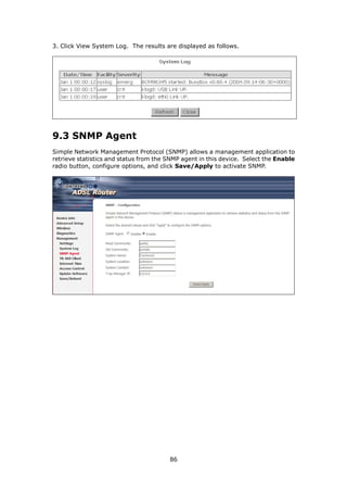
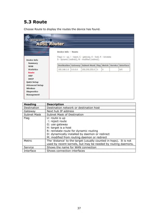
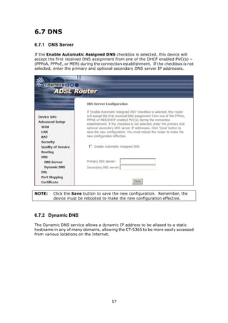
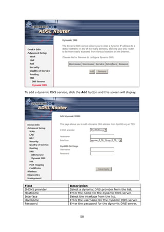
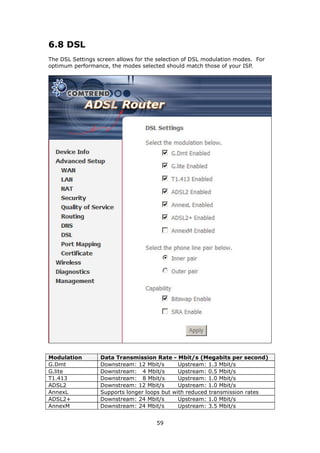
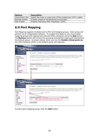
The document provides information about Comtrend's CT-5365 ADSL2+ Wireless Router, including its features, hardware installation instructions, and procedures for accessing the web user interface. Some key points:
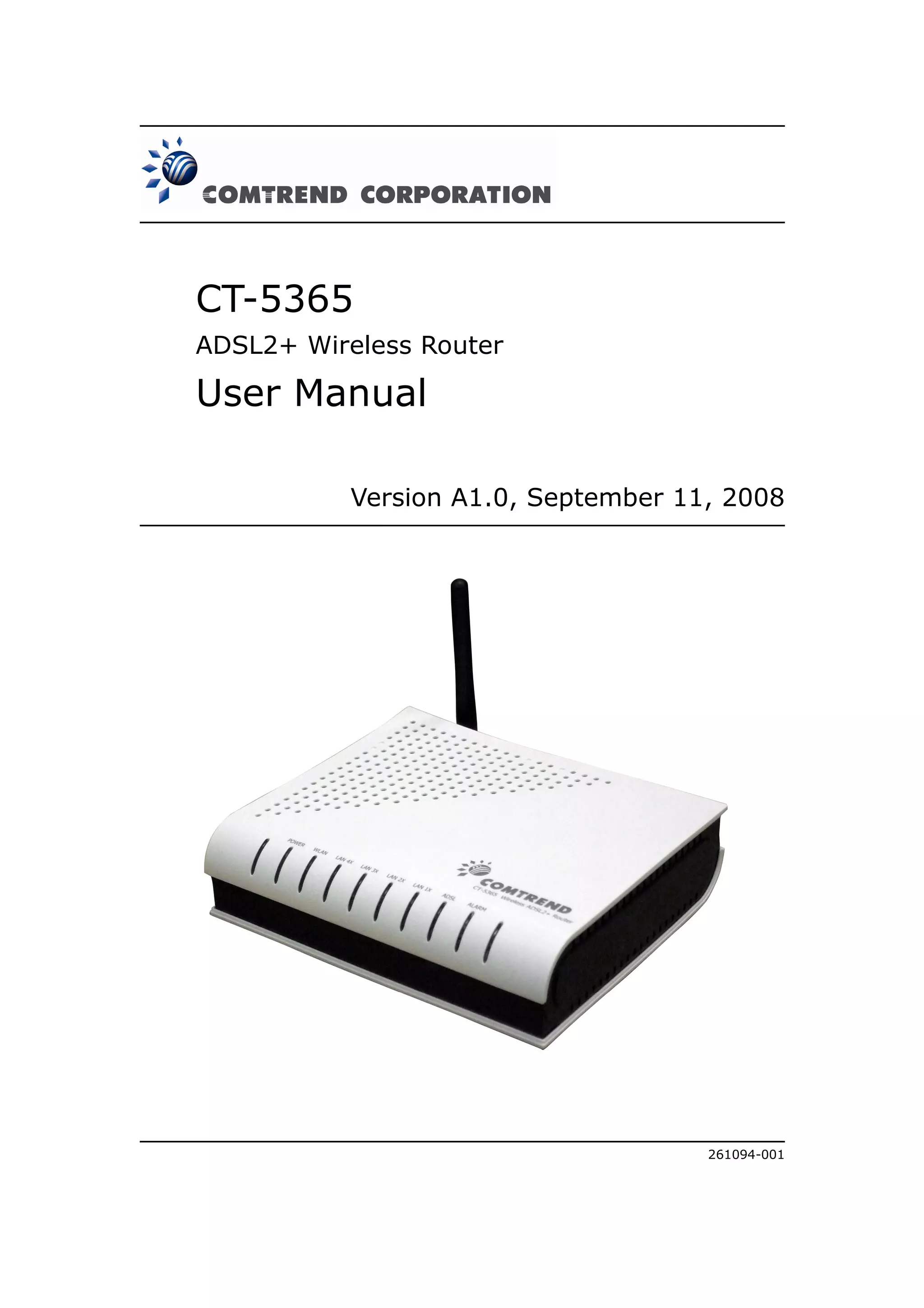
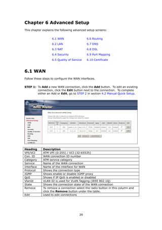
1. The CT-5365 is an ADSL2+ router with 4 Ethernet ports and integrated 802.11g wireless access point. It supports up to 16 virtual connections and includes security features like firewall, MAC/IP filtering, and WPA/WPA2 encryption.
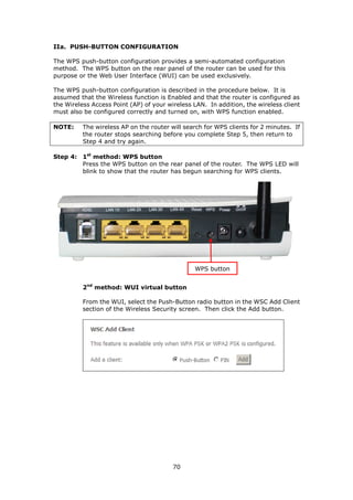
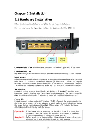
2. Hardware installation involves connecting an Ethernet cable from the WAN port to the ADSL line, and Ethernet cables from the LAN ports to devices. The reset and WPS buttons are also explained.


![Chapter 7 Wireless
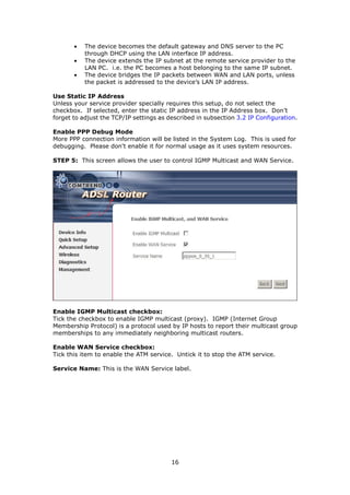
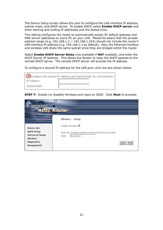
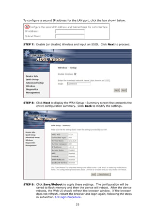
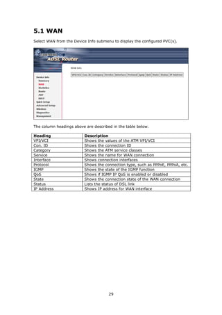
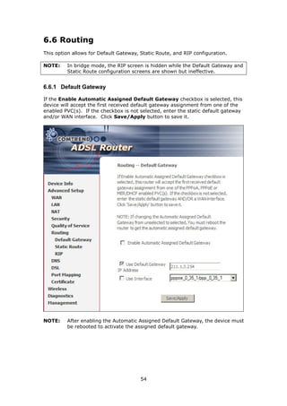
The Wireless submenu provides access to WLAN configuration settings including
wireless network name, channel restrictions (based on country), security, and
quality of services features, access point or bridging behavior and station info.
7.1 Basic
The Basic option allows you to configure basic features of the wireless LAN interface.
You can enable or disable the wireless LAN interface, hide the network from active
scans, set the wireless network name (also known as SSID) and restrict the channel
set based on country requirements.
Click Save/Apply to configure the basic wireless options.
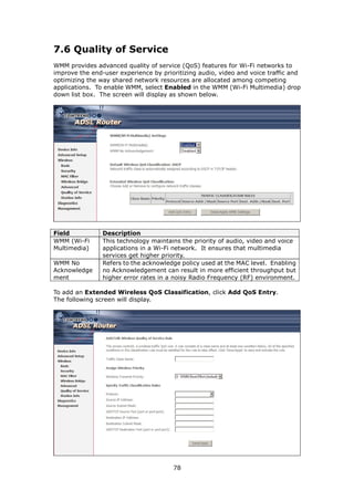
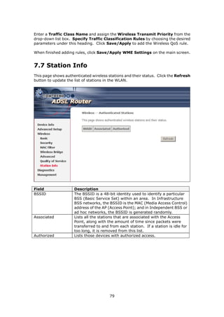
Field Description
Enable Wireless A checkbox that enables (default) or disables the wireless
LAN interface. When selected, the Web UI displays Hide
Access point, SSID, BSSID and Country settings.
Hide Access Point Select Hide Access Point to protect the access point from
detection by wireless active scans. To check AP status in
Windows XP, open Network Connections from the start
Menu and select View Available Network Connections.
If the access point is hidden, it will not be listed there. To
connect a client to a hidden access point, the station must
add the access point manually to its wireless configuration.
SSID Sets the wireless network name. SSID stands for Service Set
Identifier. All stations must be configured with the correct
[1-32 characters] SSID to access the WLAN. If the SSID does not match, that
user will not be granted access.
BSSID The BSSID is a 48-bit identity used to identify a particular
BSS (Basic Service Set) within an area. In Infrastructure BSS
networks, the BSSID is the MAC (Media Access Control)
address of the AP (Access Point); and in Independent BSS or
ad hoc networks, the BSSID is generated randomly.
65](https://image.slidesharecdn.com/routertelefonicact-5365a1-0-121115065124-phpapp02/85/Router-telefonica-ct-5365-a1-0-66-320.jpg)