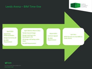
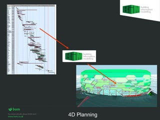
BIM was trialled on the Leeds Arena project starting in April 2011 when BAM decided to use it. The key benefits included:
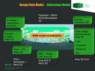
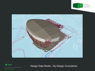
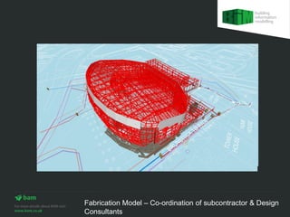
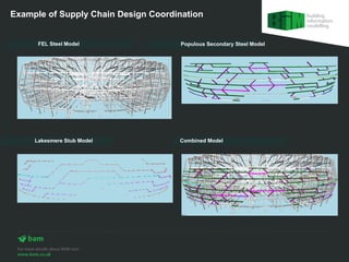
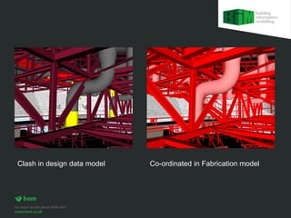
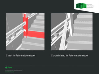
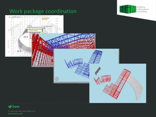
1) Coordinating design information from multiple consultants in 3D to avoid clashes both in the design data model and fabrication model.
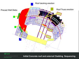
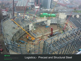
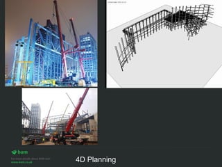
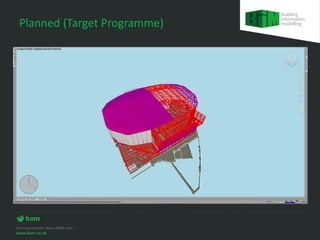
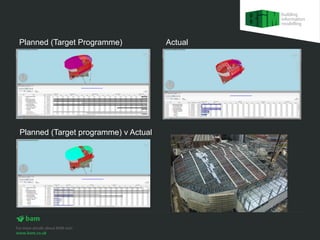
2) 4D planning to sequence construction activities like precast and structural steel erection.
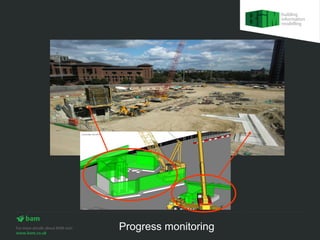
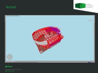
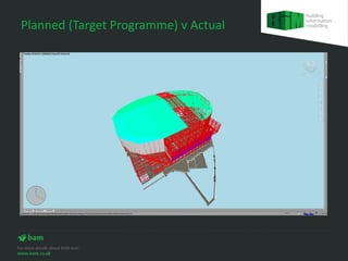
3) Monitoring actual construction progress against the planned target programme.
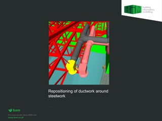
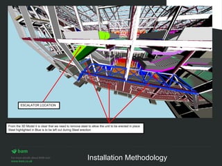
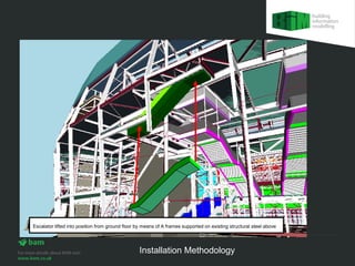
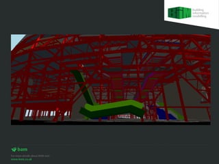
4) Coordinating installation details like removing steel to allow escalator installation.
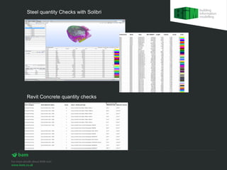
5) Checking steel and concrete quantities directly from the Revit and Tekla models.
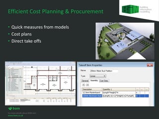
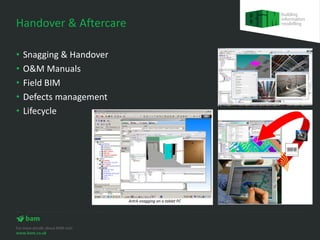
6) Potential future benefits for cost planning, procurement, handover and aftercare.


![Hi tech engineering services [airport case study]](https://cdn.slidesharecdn.com/ss_thumbnails/hitechengineeringservicesairportcasestudy-120717052506-phpapp02-thumbnail.jpg?width=640&height=640&fit=bounds)


