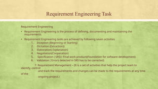
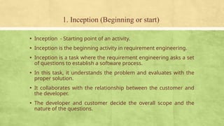
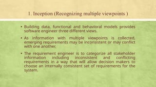
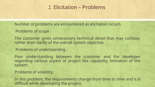
Requirement Engineering Task
Requirement Engineering
▪ Requirement Engineering is the process of defining, documenting and maintaining the
requirements.
▪ Requirement Engineering tasks are achieved by following seven activities
1. Inception (Beginning or Starting)
2. Elicitation (Extraction))
3. Elaboration( Explanation)
4. Negotiation(Cooperation)
5. Specification ( SRS) ( Final work product)(Foundation for software development)
6. Validation ( Errors detected in SRS has to be corrected)
7. Requirement Management – (It is a set of activities that help the project team to
identify, control
and track the requirements and changes can be made to the requirements at any time
of the
ongoing project.)
1. Inception (Beginning or start)
▪ Inception - Starting point of an activity.
▪ Inception is the beginning activity in requirement engineering.
▪ Inception is a task where the requirement engineering asks a set
of questions to establish a software process.
▪ In this task, it understands the problem and evaluates with the
proper solution.
▪ It collaborates with the relationship between the customer and
the developer.
▪ The developer and customer decide the overall scope and the
nature of the questions.
1. Inception (Identifying the stakeholders)
▪ It identifies the stakeholders.
▪ Stakeholders may be individual group or organization, those
who can positively or negatively impact the output of the
projects.
▪ Stakeholders identification process is one of the most
important process in project management because projects
are undertaken to fulfil the requirements of stakeholders.
1. Inception (Recognizing multiple viewpoints )
▪ Building data, functional and behavioral models provides
software engineer three different views.
▪ As information with multiple viewpoints is collected,
emerging requirements may be inconsistent or may conflict
with one another.
▪ The requirement engineer is to categorize all stakeholder
information including inconsistent and conflicting
requirements in a way that will allow decision makers to
choose an internally consistent set of requirements for the
system.
1. Inception (Working towards collaboration)
▪ Customers and other stakeholders must collaborate among
themselves and with developer for the successful system.
▪ The first set of questions focuses on the customer and other
stakeholders, overall goals and benefits.
Example
▪ Who is behind the request of the work?
▪ Who will use the solution?
▪ What will be the economic benefit of a successful solution?
▪ Is there another source for the solution that you need?
1. Inception (Working towards collaboration)
▪ The final set of questions focuses on the effective of the
communication activity itself.
Example
▪ Are my questions relevant to the problem that you have?
▪ Can anyone else provide additional information?
▪ Am I asking too many questions?
1. Inception (Working towards collaboration)
▪ The next set of questions enables the software engineering
team to gain a better understanding of the problem.
Example
▪ How would you characterize “good” output that would be generated
by a successful solution?
▪ What problem will this solution address?
▪ Can you show me the business environment in which the solution
will be used?
2. Elicitation (bring out) requirement from all stakeholders
Elicitation is “Requirement gathering”.
Ask the customer, the users, and others
▪ what the objectives for the system or product are,
▪ what is to be accomplished,
▪ how the system or product fits into the needs of the
business, and finally,
▪ how the system or product is to be used on a day-to-day
basis.
2. Elicitation – Problems
Number of problems are encountered as elicitation occurs.
Problems of scope :
The customer gives unnecessary technical detail that may confuse,
rather than clarify of the overall system objective.
Problems of understanding :
Poor understanding between the customer and the developer
regarding various aspect of project like capability, limitation of the
system.
Problems of volatility:
In this problem, the requirements change from time to time and it is
difficult while developing the project.
2. Elicitation – Methods
There are a number of requirements elicitation methods.
Few of them are listed below –
 Interviews
 Brainstorming Sessions
 Facilitated Application Specification Technique (FAST)
 Quality Function Deployment (QFD)
 Use Case Approach
The success of an elicitation technique used depends on the
maturity of the developers, users and the customer involved.
2. Elicitation – Interviews
Interviews:
• Objective of conducting an interview is to understand the
customer’s expectations from the software.
• Interviews maybe be open ended or structured.
• In open ended interviews there is no pre-set agenda. Context
free questions may be asked to understand the problem.
• In structured interview, agenda of fairly open questions is
prepared.
2. Elicitation – Brainstorming Sessions
Brainstorming Sessions:
• It is a group technique
• It is intended to generate lots of new ideas hence providing a
platform to share views
• A highly trained facilitator is required to handle group bias
and group conflicts.
• Every idea is documented so that everyone can see it.
• Finally a document is prepared which consists of the list of
requirements and their priority if possible.
2. Elicitation – Facilitated Application Specification Technique
(FAST)
Facilitated Application Specification Technique:
• It’s objective is to bridge the expectation gap – difference between what the developers
think they are supposed to build and what customers think they are going to get.
• A team oriented approach is developed for requirements gathering.
Each attendee is asked to make a list of objects that are-
• Part of the environment that surrounds the system
• Produced by the system
• Used by the system
• Each participant prepares his/her list, different lists are then combined, redundant
entries are eliminated, team is divided into smaller sub-teams to develop mini-
specifications and finally a draft of specifications is written down using all the inputs from
the meeting.
2. Elicitation – Quality Function Deployment
• In this technique customer satisfaction is of prime concern, hence it emphasizes on
the requirements which are valuable to the customer.
• 3 types of requirements are identified –
• Normal requirements – In this the objective and goals of the proposed software are
discussed with the customer. Example – normal requirements for a result
management system may be entry of marks, calculation of results etc
• Expected requirements – These requirements are so obvious that the customer
need not explicitly state them. Example – protection from unauthorised access.
• Exciting requirements – It includes features that are beyond customer’s
expectations and prove to be very satisfying when present. Example – when an
unauthorised access is detected, it should backup and shutdown all processes.
2. Elicitation – Quality Function Deployment
The major steps involved in this procedure are –
1. Identify all the stakeholders, eg. Users, developers, customers etc
2. List out all requirements from customer.
3. A value indicating degree of importance is assigned to each requirement.
4. In the end the final list of requirements is categorized as –
• It is possible to achieve
• It should be deferred and the reason for it
• It is impossible to achieve and should be dropped off.
2. Elicitation – Use Case Approach
This technique combines text and pictures to provide a better understanding of the
requirements.
The use cases describe the ‘what’, of a system and not ‘how’. Hence they only give a
functional view of the system.
The components of the use case deign includes three major things – Actor, Use cases, use
case diagram.
Actor – It is the external agent that lies outside the system but interacts with it in some
way. An actor maybe a person, machine etc. It is represented as a stick figure. Actors can
be primary actors or secondary actors.
Primary actors – It requires assistance from the system to achieve a goal.
Secondary actor – It is an actor from which the system needs assistance.
2. Elicitation – Use Case Approach
This technique combines text and pictures to provide a better understanding of the
requirements.
The use cases describe the ‘what’, of a system and not ‘how’. Hence they only give a
functional view of the system.
The components of the use case deign includes three major things – Actor, Use
cases, use case diagram.
1. Actor – It is the external agent that lies outside the system but interacts with it in
some way. An actor maybe a person, machine etc. It is represented as a stick
figure. Actors can be primary actors or secondary actors.
• Primary actors – It requires assistance from the system to achieve a goal.
• Secondary actor – It is an actor from which the system needs assistance.
2. Elicitation – Use Case Approach
2. Use cases – They describe the sequence of interactions between actors and the system.
They capture who(actors) do what(interaction) with the system. A complete set of use
cases specifies all possible ways to use the system.
3. Use case diagram – A use case diiagram graphically represents what happens when an
actor interacts with a system. It captures the functional aspect of the system.
• A stick figure is used to represent an actor.
• An oval is used to represent a use case.
• A line is used to represent a relationship between an actor and a use case.
2. Elicitation – Use Case Approach
Eliciting requirement steps
▪ Collaborative requirements gathering
▪ Quality Function Deployment (QFD)
▪ Usage scenarios
▪ Elicitation work product
Collaborative requirements gathering
▪ Gathering the requirements by conducting the meetings
between developer and customer.
▪ Fix the rules for preparation and participation.
▪ The main motive is to identify the problem, give the
solutions for the elements, negotiate the different
approaches and specify the primary set of solution
requirements in an environment which is valuable for
achieving goal.
Quality Function Deployment (QFD)
▪ In this technique, translate the customer need into the technical
requirement for the software.
▪ QFD system designs a software according to the demands of the
customer.
▪ QFD consist of three types of requirement:
Normal requirements
▪ The objective and goal are stated for the system through the
meetings with the customer.
▪ For the customer satisfaction these requirements should be
there.
Quality Function Deployment (QFD)
Expected requirement
 These requirements are implicit.
 These are the basic requirement that not be clearly told by the customer,
but also the customer expect that requirement.
Exciting requirements
 These features are beyond the expectation of the customer.
 The developer adds some additional features or unexpected feature into
the software to make the customer more satisfied.
 For example, the mobile phone with standard features, but the
developer adds few additional functionalities like voice searching, multi-
touch screen etc. then the customer more exited about that feature.
Usage scenarios
▪ Till the software team does not understand how the features
and function are used by the end users it is difficult to move
technical activities.
▪ To achieve above problem the software team produces a set
of structure that identify the usage for the software.
▪ This structure is called as 'Use Cases'.
Elicitation work product
▪ The work product created as a result of requirement
elicitation that is depending on the size of the system or
product to be built.
▪ The work product consists of a statement need, feasibility,
statement scope for the system.
▪ It also consists of a list of users participate in the
requirement elicitation.
Analysis Model in Software Engineering
• Analysis model operates as a link between the 'system description'
and the 'design model’.
• In the analysis model, information, functions and the behaviour of
the system is defined and these are translated into the
architecture, interface and component level design in the 'design
modeling'.
Elements of Analysis model
1. Scenario based element
2. Class based elements
3. Behavioral elements
4. Flow oriented elements
Scenario based element
Class based elements
Behavioral elements
Flow oriented elements
Analysis Rules of Thumb
The rules of thumb that must be followed while creating the analysis model.
• The model focuses on the requirements in the business domain.
• Every element in the model helps in understanding the software requirement and focus on
the information, function and behaviour of the system.
• The consideration of infrastructure and nonfunctional model delayed in the design.
• For example, the database is required for a system, but the classes, functions and behavior
of the database are not initially required. If these are initially considered then there is a
delay in the designing.
• Throughout the system minimum coupling is required. The interconnections between the
modules is known as 'coupling'.
• The analysis model gives value to all the people related to model.
• The model should be simple as possible. Because simple model always helps in easy
understanding of the requirement.

requirement-engineering-task-unit-2.pptx

  • 1.
    Requirement Engineering Task RequirementEngineering ▪ Requirement Engineering is the process of defining, documenting and maintaining the requirements. ▪ Requirement Engineering tasks are achieved by following seven activities 1. Inception (Beginning or Starting) 2. Elicitation (Extraction)) 3. Elaboration( Explanation) 4. Negotiation(Cooperation) 5. Specification ( SRS) ( Final work product)(Foundation for software development) 6. Validation ( Errors detected in SRS has to be corrected) 7. Requirement Management – (It is a set of activities that help the project team to identify, control and track the requirements and changes can be made to the requirements at any time of the ongoing project.)
  • 2.
    1. Inception (Beginningor start) ▪ Inception - Starting point of an activity. ▪ Inception is the beginning activity in requirement engineering. ▪ Inception is a task where the requirement engineering asks a set of questions to establish a software process. ▪ In this task, it understands the problem and evaluates with the proper solution. ▪ It collaborates with the relationship between the customer and the developer. ▪ The developer and customer decide the overall scope and the nature of the questions.
  • 3.
    1. Inception (Identifyingthe stakeholders) ▪ It identifies the stakeholders. ▪ Stakeholders may be individual group or organization, those who can positively or negatively impact the output of the projects. ▪ Stakeholders identification process is one of the most important process in project management because projects are undertaken to fulfil the requirements of stakeholders.
  • 4.
    1. Inception (Recognizingmultiple viewpoints ) ▪ Building data, functional and behavioral models provides software engineer three different views. ▪ As information with multiple viewpoints is collected, emerging requirements may be inconsistent or may conflict with one another. ▪ The requirement engineer is to categorize all stakeholder information including inconsistent and conflicting requirements in a way that will allow decision makers to choose an internally consistent set of requirements for the system.
  • 5.
    1. Inception (Workingtowards collaboration) ▪ Customers and other stakeholders must collaborate among themselves and with developer for the successful system. ▪ The first set of questions focuses on the customer and other stakeholders, overall goals and benefits. Example ▪ Who is behind the request of the work? ▪ Who will use the solution? ▪ What will be the economic benefit of a successful solution? ▪ Is there another source for the solution that you need?
  • 6.
    1. Inception (Workingtowards collaboration) ▪ The final set of questions focuses on the effective of the communication activity itself. Example ▪ Are my questions relevant to the problem that you have? ▪ Can anyone else provide additional information? ▪ Am I asking too many questions?
  • 7.
    1. Inception (Workingtowards collaboration) ▪ The next set of questions enables the software engineering team to gain a better understanding of the problem. Example ▪ How would you characterize “good” output that would be generated by a successful solution? ▪ What problem will this solution address? ▪ Can you show me the business environment in which the solution will be used?
  • 8.
    2. Elicitation (bringout) requirement from all stakeholders Elicitation is “Requirement gathering”. Ask the customer, the users, and others ▪ what the objectives for the system or product are, ▪ what is to be accomplished, ▪ how the system or product fits into the needs of the business, and finally, ▪ how the system or product is to be used on a day-to-day basis.
  • 9.
    2. Elicitation –Problems Number of problems are encountered as elicitation occurs. Problems of scope : The customer gives unnecessary technical detail that may confuse, rather than clarify of the overall system objective. Problems of understanding : Poor understanding between the customer and the developer regarding various aspect of project like capability, limitation of the system. Problems of volatility: In this problem, the requirements change from time to time and it is difficult while developing the project.
  • 10.
    2. Elicitation –Methods There are a number of requirements elicitation methods. Few of them are listed below –  Interviews  Brainstorming Sessions  Facilitated Application Specification Technique (FAST)  Quality Function Deployment (QFD)  Use Case Approach The success of an elicitation technique used depends on the maturity of the developers, users and the customer involved.
  • 11.
    2. Elicitation –Interviews Interviews: • Objective of conducting an interview is to understand the customer’s expectations from the software. • Interviews maybe be open ended or structured. • In open ended interviews there is no pre-set agenda. Context free questions may be asked to understand the problem. • In structured interview, agenda of fairly open questions is prepared.
  • 12.
    2. Elicitation –Brainstorming Sessions Brainstorming Sessions: • It is a group technique • It is intended to generate lots of new ideas hence providing a platform to share views • A highly trained facilitator is required to handle group bias and group conflicts. • Every idea is documented so that everyone can see it. • Finally a document is prepared which consists of the list of requirements and their priority if possible.
  • 13.
    2. Elicitation –Facilitated Application Specification Technique (FAST) Facilitated Application Specification Technique: • It’s objective is to bridge the expectation gap – difference between what the developers think they are supposed to build and what customers think they are going to get. • A team oriented approach is developed for requirements gathering. Each attendee is asked to make a list of objects that are- • Part of the environment that surrounds the system • Produced by the system • Used by the system • Each participant prepares his/her list, different lists are then combined, redundant entries are eliminated, team is divided into smaller sub-teams to develop mini- specifications and finally a draft of specifications is written down using all the inputs from the meeting.
  • 14.
    2. Elicitation –Quality Function Deployment • In this technique customer satisfaction is of prime concern, hence it emphasizes on the requirements which are valuable to the customer. • 3 types of requirements are identified – • Normal requirements – In this the objective and goals of the proposed software are discussed with the customer. Example – normal requirements for a result management system may be entry of marks, calculation of results etc • Expected requirements – These requirements are so obvious that the customer need not explicitly state them. Example – protection from unauthorised access. • Exciting requirements – It includes features that are beyond customer’s expectations and prove to be very satisfying when present. Example – when an unauthorised access is detected, it should backup and shutdown all processes.
  • 15.
    2. Elicitation –Quality Function Deployment The major steps involved in this procedure are – 1. Identify all the stakeholders, eg. Users, developers, customers etc 2. List out all requirements from customer. 3. A value indicating degree of importance is assigned to each requirement. 4. In the end the final list of requirements is categorized as – • It is possible to achieve • It should be deferred and the reason for it • It is impossible to achieve and should be dropped off.
  • 16.
    2. Elicitation –Use Case Approach This technique combines text and pictures to provide a better understanding of the requirements. The use cases describe the ‘what’, of a system and not ‘how’. Hence they only give a functional view of the system. The components of the use case deign includes three major things – Actor, Use cases, use case diagram. Actor – It is the external agent that lies outside the system but interacts with it in some way. An actor maybe a person, machine etc. It is represented as a stick figure. Actors can be primary actors or secondary actors. Primary actors – It requires assistance from the system to achieve a goal. Secondary actor – It is an actor from which the system needs assistance.
  • 17.
    2. Elicitation –Use Case Approach This technique combines text and pictures to provide a better understanding of the requirements. The use cases describe the ‘what’, of a system and not ‘how’. Hence they only give a functional view of the system. The components of the use case deign includes three major things – Actor, Use cases, use case diagram. 1. Actor – It is the external agent that lies outside the system but interacts with it in some way. An actor maybe a person, machine etc. It is represented as a stick figure. Actors can be primary actors or secondary actors. • Primary actors – It requires assistance from the system to achieve a goal. • Secondary actor – It is an actor from which the system needs assistance.
  • 18.
    2. Elicitation –Use Case Approach 2. Use cases – They describe the sequence of interactions between actors and the system. They capture who(actors) do what(interaction) with the system. A complete set of use cases specifies all possible ways to use the system. 3. Use case diagram – A use case diiagram graphically represents what happens when an actor interacts with a system. It captures the functional aspect of the system. • A stick figure is used to represent an actor. • An oval is used to represent a use case. • A line is used to represent a relationship between an actor and a use case.
  • 19.
    2. Elicitation –Use Case Approach
  • 20.
    2. Elicitation –Use Case Approach
  • 21.
    Eliciting requirement steps ▪Collaborative requirements gathering ▪ Quality Function Deployment (QFD) ▪ Usage scenarios ▪ Elicitation work product
  • 22.
    Collaborative requirements gathering ▪Gathering the requirements by conducting the meetings between developer and customer. ▪ Fix the rules for preparation and participation. ▪ The main motive is to identify the problem, give the solutions for the elements, negotiate the different approaches and specify the primary set of solution requirements in an environment which is valuable for achieving goal.
  • 23.
    Quality Function Deployment(QFD) ▪ In this technique, translate the customer need into the technical requirement for the software. ▪ QFD system designs a software according to the demands of the customer. ▪ QFD consist of three types of requirement: Normal requirements ▪ The objective and goal are stated for the system through the meetings with the customer. ▪ For the customer satisfaction these requirements should be there.
  • 24.
    Quality Function Deployment(QFD) Expected requirement  These requirements are implicit.  These are the basic requirement that not be clearly told by the customer, but also the customer expect that requirement. Exciting requirements  These features are beyond the expectation of the customer.  The developer adds some additional features or unexpected feature into the software to make the customer more satisfied.  For example, the mobile phone with standard features, but the developer adds few additional functionalities like voice searching, multi- touch screen etc. then the customer more exited about that feature.
  • 25.
    Usage scenarios ▪ Tillthe software team does not understand how the features and function are used by the end users it is difficult to move technical activities. ▪ To achieve above problem the software team produces a set of structure that identify the usage for the software. ▪ This structure is called as 'Use Cases'.
  • 26.
    Elicitation work product ▪The work product created as a result of requirement elicitation that is depending on the size of the system or product to be built. ▪ The work product consists of a statement need, feasibility, statement scope for the system. ▪ It also consists of a list of users participate in the requirement elicitation.
  • 27.
    Analysis Model inSoftware Engineering • Analysis model operates as a link between the 'system description' and the 'design model’. • In the analysis model, information, functions and the behaviour of the system is defined and these are translated into the architecture, interface and component level design in the 'design modeling'.
  • 28.
    Elements of Analysismodel 1. Scenario based element 2. Class based elements 3. Behavioral elements 4. Flow oriented elements
  • 29.
  • 30.
  • 31.
  • 32.
  • 33.
    Analysis Rules ofThumb The rules of thumb that must be followed while creating the analysis model. • The model focuses on the requirements in the business domain. • Every element in the model helps in understanding the software requirement and focus on the information, function and behaviour of the system. • The consideration of infrastructure and nonfunctional model delayed in the design. • For example, the database is required for a system, but the classes, functions and behavior of the database are not initially required. If these are initially considered then there is a delay in the designing. • Throughout the system minimum coupling is required. The interconnections between the modules is known as 'coupling'. • The analysis model gives value to all the people related to model. • The model should be simple as possible. Because simple model always helps in easy understanding of the requirement.