+971581248768>> SAFE AND ORIGINAL ABORTION PILLS FOR SALE IN DUBAI AND ABUDHA...
reparacion de tv sony completa y sujerencias
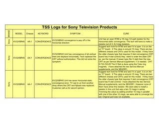
1. BRAND
MODEL Chassis KEYWORD SYMPTOM CURE
Sony
KV32XBR45 AA-1 CONVERGENCE
KV32XBR45 convergence is way off in the
horizontal direction
Unit has an open R789 a 18 meg 1/2 watt resistor for the
Horizontal static convergence. The tech will have to make a
resistor out of 3, 6.2 meg resistors.
Sony
KV32XBR45 AA-1 CONVERGENCE
KV32XBR45 Unit has convergence of all vertical
lines are displace horizontally. Tech replaced the
CRT without authorization. This did not solve the
symptom
Suggest tech look for R789 and see if it is open It is on the
on "C" board. It The value is around 10 meg. There are two
different chassis and CRTs used for this model. If they have
the older chassis type that requires H stat convergence (CRT
board has H stat control) they need to order the older CRT
as per the manual. If newer type (No H stat) then the new
CRT as per Service Manual supplement -1 is needed. CRT
8-733-743-05 The H Stat is done using the Yoke ring
magnets. I have attached the two Service Manual
supplements, and the SB325R1.
Sony
KV32XBR45 AA-1 CONVERGENCE
KV32XBR45 Unit has sever Horizontal static
convergence error. TV cae to us from another
shop where the CRT and flyback was replaced.
Customer call us for secont opinion.
Suggest tech look for R789 and see if it is open It is on the
on "C" board. It The value is around 10 meg. There are two
different chassis and CRTs used for this model. If they have
the older chassis type that requires H stat convergence (CRT
board has H stat control) I have attached the two Service
Manual supplements, and the SB325R1. However none of
them have show this resistor. We were able to install a
resistor in this unit that was a two 10 megs in series.
Trimming the value by adding another 10 meg in parallel
with one of the other 10 megs. we were able to converge the
set. Original part was not available.
TSS Logs for Sony Television Products
2. BRAND
MODEL Chassis KEYWORD SYMPTOM CURE
TSS Logs for Sony Television Products
Sony
KV32XBR45 AA-1 CONVERGENCE
Unit has mis-convergence of red and blue vertical
lines. They are displace horizontally. Tech
replaced the CRT without correcting the symptom.
R789 open H-state not operational. What I'm finding is a
resistor that appears to be open on this "C" board It is R789
The value cannot be read nor is it listed in the ESI software
parts list. Trying another value from 10 to 20 megohms. This
resistor is in the ground return of the H-stat resistor that is
installed in the CRT. Tech needs to try different values to try
and make this set converge horizontally. This TV converged
with a 10 megohm resistor.
Sony
KV32XBR45 AA-1 CONVERGENCE
Unit has nis-convergence of red & blue vertical
lines which are displaced horizontally. Tech
replaced the CRT. This did not solve the problem.
Suggest tech look for R789 and see if it is open It is on the
on "C" board. The value is around 10 meg. There are two
different chassis and CRTs used for this model. If they have
the older chassis type that requires H stat convergence (CRT
board has H stat control) they need to order the older CRT as
per the manual. If newer type (No H stat) then the new CRT
as per Service Manual supplement -1 is needed. CRT 8-
733-743-05 The H Stat is done using the Yoke ring magnets.
Sony
KV32TS46 AA-1 dead
Unit was dead. has shorted horizontal output and
shorted Q601, & Q602 components in power
supply replaced. After replacement unit will turn on
but still has no secondary voltage output of power
transformer. All relays click but no high voltage.
Has sound.
Tech needs to check the condition or RY602. RY602 is the
switching relay that turn on and off the set. The relay is
"HOT" switched. In other words one side of the relay is
connected to power oscillator output that runs nearly 350
vac Peak to Peak at 90Khz. Once the relay is closed this
energy is placed across the power output transformer and
provides the drive necessary to produce the B+.Measuring
the input voltage of the relay to "HOT' ground found it to be
150 volts DC mode. But on the other side of relay we has 3
volts DC mode. Unit has defective RY602 relay.
SONY
KV32XBR45 AA-1 GEOMETRY
Unit is trying to constantly adjust the vertical height
and horizontal size intermittently.
When monitoring the E/W Pin output of the M board the
signal was very instable. It was decided to replace IC351 the
Jungle IC. This corrected the trouble.
3. BRAND
MODEL Chassis KEYWORD SYMPTOM CURE
TSS Logs for Sony Television Products
Sony
KV32TW77 AA-1 No high voltage
Sony AA-1 chassis. Unit no high voltage or sound.
RY602 latched at turn on. Tech replaced the
flyback and Q601, Q602, VDR601, VDR602,
VDR603 & R607. After theses components were
replaced the unit still did not produce secondary
B+. Only 3 volts on the collector of the Horizontal
output.
Inspected the Power oscillator and discovered that it was
running and producing 167 volts DC at the input side of
RY602, but a <13 volts on the low side. Jumping RY602
restored High voltage. Unit had a bad RY602 relay in the
power supply.
Sony
KV32XBR37 AA-1 NO RASTER
KV32XBR37 serial 80139945. Unit has no raster.
Has sound, CRT filaments, and high voltage. Led
in front is flashing
Tech may have a IK failure. When bringing up the G2 the
raster will appear with full vertical sweep and a purple
screen. Not much green. Tech needs to look at the IK buffer
collectors on Q771, Q772, & Q773. Normally with beam
current there shall be about 1 volt on each collector. With the
CRT Socket removed all collectors must drop to "0" volts.
Q771 did not. It was 1.2 volts regardless if the tube was
connected or not. Tech needs to short Q771(E&B) and see if
the collector will drop. It did not. TV will need a replacement
Q771. Replacement cured the symptom.
Sony
KV32XBR85 AA-1 NO RASTER
KV32XBR85 Unit has no raster. Has sound and
weak OSD. Stand-by light is not flashing.
Unit appears to have a normal IK feed back to the jungle IC.
Screen voltages are 670 vdc and the cathode is running at
180 vdc. Unit looks like a defective Jungle IC. Replacing the
Jungle IC corected the symptom.
Sony
KV32XBR250 AA-1 Noise Video
Sony KV32XBR50 This customer has a Goldstar
8mm/VHS dual deck VCR located under this
television on the built in shelf. When customer
uses the 8mm deck the playback of the tape has
corrupted audio, and poor tracking performance
when played back on this television
The design of the 8mm format is significantly different from
that of the VHS. The 8MM format does not have any
stationary heads and completely relies on the signals from
the rotary video heads on drum. 4 ATF (Auto Tracking Fix)
carriers are recorded on to the tape. Apparently the shielding
in the 8 mm VCR, this close proximity to the TV, and the lack
of shielding in the Sony TV caused the corruption of the 4
ATF signals. Placing the VCR on the bottom shelf of the TV
cabinet corrected the symptom.
4. BRAND
MODEL Chassis KEYWORD SYMPTOM CURE
TSS Logs for Sony Television Products
Sony
KV36FV15 AA-1 RASTER
KV36FV15 Unit will turn on with the front panel
control but the set will not develop raster or sound.
The high voltage will turn but no raster. After 3
minutes the raster and sound will appear
Tech needs to look into the Data & Clock lines of the chassis.
These lines must be 5 volts peak to peak and have a typical
word length of 1000 milli seconds. Tech discovered the SDA
pulses were 3.3 volts peak to peak whereas the CLK pulses
were at 5 volts. Tech had to isolate each load on the SDA
line and found the PIP tuner was responsible for loading
down the DATA line.
Sony
KV32TW67 AA-1 remote
KV32TW67 serial 70040800 Remote does not
function RMY102 remote is being used. The menu
displays when in the "menu" button on the remote
is pressed. We are able to highlight each area of
the menus selection which are the "Video, Timer,
Setup, and closed caption" choices. But when
selection of any of these are tried nothing happens.
In the service mode Service menu the service
menus comes up with AFC as the first selection.
However the binary number (1000) displayed
under the word "Service" keeps changing from
1000 to 1100) randomly
The remote has been changed without effecting the
symptom.. This appears to be a system control failure. All ID
codes are within normal values. Suggest the tech replace the
following components IC101 and IC102 are 8-752-856-00
and 8-759-280-74. The components correct the symptom.
Sony
KV32XBR35 AA-1 shut down
Unit will shut down each time the Remote
headphones circuit is turned on.
Unit has an intermittent short to ground on the IR12 volt line
located at the output of IC202(3-4) located on the "A" board.
This short was caused by a solder splace on that circuit
Sony
KV32V16 AA-1 shutdown
KV32V16 serial 7089163 Unit will not stay on.
Goes into shut down immediately after turn on
. When HV comes up the signal at the Collector of the
horizontal output transistor is normal. No shorts can be found
in the power supply. PM501(1-810-061-21) & IC601(1-810-
477-11). PM501 was to culprit in this case.
Sony
KV32XBR45 AA-1 WEAK VIDEO
Sony KV32XBR45 Unit has a very faint picture But
the OSD is fine. Problem shows up in the tuner
and video input mode. Tech ordered Q401 but did
not correct the symptom
There is video at the base of Q401 but not at the emitter.
Q401 measures 9 volts on all elements. Base must be 4.5
volts. Transistor is in cut off. Bases and emitter are the same
9 volts. Unit has open R617 a 680 ohm resistor.
5. BRAND
MODEL Chassis KEYWORD SYMPTOM CURE
TSS Logs for Sony Television Products
Sony
KV32S40 AA-2 A.C Hum
KV32S40 serial 9028282 that has a low level
audio hum in the video input or tuner mode.
Looked in the FPR on web site but could fine
nothing on the subject. The hum is at 60 Hertz
The hum is a result of magnetic flux from the vertical
deflection yoke. The 60 hz is radiating into the low level
audio circuits through inductive pick up from lead dress and
ground loops. To minimize these Remove JW086 and
JW1007.Add 22AWG wire from JW270 to ground side of
R477. This wire should be on the top side of the A-board and
routed to following the audio signal lines from IC1401 (audio
Sony
KV27V10 AA-2 AC leakage claim
KV27V10 serial 7104657. When the CATV rep
was out a few days ago he plugged in the set in to
wall and when the prongs made contact with the
AC wall outlet a small spark was seen. The CATV
rep exclaimed, "The television is a fire hazard,
and you need to call for service!" He left the set
unplugged and we went out on this day.
Our tech plugged in the set and found the set did have a
spark as soon as the set was plugged in the AC outlet. This
is perfectly normal because this chassis has to fully charge 2
820 mfd electrolytics in a voltage doubler configuration. This
causes a tremendous amount of in rush current that may
draw several amperes until the filters are charges up. This
will cause a contact arc the moment the set is connected to
the AC line. This set poses no more fire hazard than any
other electrical device that plugs into the AC outlet. We also
performed an A.C leakage test on the chassis and found that
it was less than .015 volts measured at the customers ground
connection and neutral.
Sony
KV32V25 AA-2 arcing
KV32V25 serial 7036251. Unit has an arcing inside
the flyback transformer. Tech replaced the
transformer now the unit has a bright band at the
top of the screen. The tech replaced the jungle "IC
without effecting the symptom
Tech noticed the +15 volt source was lower than expected. It
was only 10 volts. It is not unusual. The voltage is normally
12 volts. What the tech was missing is the -15. This voltage
must be there in order for the set to have any vertical sweep.
D530 was shorted and open R536 the 0.47 ohm current
Sony
KV32V26 AA-2 arcing
KV32V26 serial 8019814. Arcing in the neck off
CRT
Tech will need replacement CRT A80JYV51X
So
ny
KV35V76 AA-2 ARCING KV35V75 CRT is arcing in the neck The CRT is bad.
Sony
KV35XBR48 AA-2 ARCING
KV35XBR48 serial 9014229. TUBE ARCING IN
THE NECK
unit will need CRT A89LJT80XZ
6. BRAND
MODEL Chassis KEYWORD SYMPTOM CURE
TSS Logs for Sony Television Products
Sony
KV27V65 AA-2 AUDIO
Audio level adjustments will not increase in a linear
fashion, instead the audio will increase rapidly in
the first 1/3 of the bar graph.
A new microprocessor is available for this unit. It is part
number T-998-600-32. It replaces the original IC001 which
was M37273MF-251
Sony
KV27S45 AA-2 AUDIO
KV27S45 serial 8046950 Unit has a very rapid
change in volume when increasing the level from
minimum to 4 notches above minimum
Tech needs to add a resistor in parallel with R432 to
effectively reduce the value of R432. This changes the
voltage divider ratio to the volume control circuit and makes
the volume circuit more linear in operation.
Sony
KV32S65 AA-2 audio
KV32S65. Serial # 8014575. Sound and picture is
fine but when the fixed or variable audio out is
connected to an external audio amp and the set is
muted a loud pop is heard in the right channel.
I had the tech try to measure if there was any DC voltages
that resided on the Variable audio output connectors. There
was "4.5" volts on the Right channel and "0" volts on the left
channel. When the "Mute" transistors on the variable line
triggered they pulled both lines to ground. When the external
amp was connected to this circuit the input capacitor for the
right channel charged with this 4.5 volts. We still had audio
on this line even though it was at a 4.5 vdc potential. But
when the Sony muted, the input capacitor inside the Big
External amp discharged and caused a tremendous pop.
C172 is a .47mfd used to decoupling the audio from IC101
the Variable audio control IC. This capacitor had 4.5 vdc on
each leg measured to ground. Removing the capacitor and
measuring the DC resistance across the cap measured 175
ohms. Replacement of the capacitor corrected the symptom.
Sony
KV27S20 AA-2 Audio
Sony KV27S20. Unit has a low pitch whine in the
left audio channel.
Problem is best heard in the video input mode with no signal
put to the input. It can be seen with an oscilloscope on one of
the output pins of IC1401 but not on the input. Part number
is 8-759-369-39. IC1401 corrected the trouble.
Sony
KV27S36 AA-2 audio
Sony KV27S36. Unit has choppy SAP audio.
Stereo 0.K.
All SAP, Stereo, and mono functions come from the Tuner
assembly and nowhere else. If a problem exists for the
S.A.P. feature all circuitry relating to the feature is replaced
when the tuner assembly is replaced. Recommend the
Tuner/IF/MTS decoder assembly. Replacement corrected the
7. BRAND
MODEL Chassis KEYWORD SYMPTOM CURE
TSS Logs for Sony Television Products
Sony
KV27V65 AA-2 audio
Sony KV27V65 Sound does not ramp up correctly.
Seems to get very loud as soon as the volume
gets higher in a very short time
I had tech get into the ID codes and reset ID2 from 239 to
175 and ID 4 from 130 to 194. Then initialize the EPROM .
Set returned to normal operation
Sony
KV35XBR35 AA-2 B&W Tracking
KV35XBR35. Unit has color temperature error in
the YUV input mode only
According to Sony tech support there is no adjustment for
this input. Refer this customer to Sony customer affairs.
Sony
KV27S22 AA-2 BRIGHT RASTER
KV27S22 serial # 8102548. Unit goes to a bright
blue screen with retrace lines then shuts down.
Unit has a defective CRT. When unit is able to turn back on
again the set will sometimes be in the video input mode.
Sony
KV35S26 AA-2 CHROMA
KV35S26 Unit has the tint phase shift and color
lock up problems only on the Hughs satellite
receiver. VCR and over air signals have solid color
lock up.
This symptom acts like it is a problem with the satellite
receiver. Inside the satellite receiver there is a NTSC
encoder which injects the 3.579547 MHz color oscillator
signal in the video. If this oscillator is too far off frequency it
will not phase lock with the 3.579545 MHz in the television.
This is a software problem with the Satalite receiver. A
software download will be available to all receivers in Late
Sony
KV35S26 AA-2 chroma
KV35S36. Unit has random chroma phase
shifting. The tint will vary radically. NTSC color
bars are not stable. "Barber Polling" effect of
colors on bars.
Suggest the tech look very close to the connection s to
IC351(4) This the Chroma AFDC filter. Components R354,
C355, C355 are in the AFCFIL circuit. It is possible the
trouble is a Jungle IC but Before replacing it is
recommended to check the aforementioned components
first. Note: when checking the components it was found that
C366 has glue touching each end of the device. The glue
effectively changed the value of the device. Cleaning the
glue and reinstalling the device corrected the problem.
8. BRAND
MODEL Chassis KEYWORD SYMPTOM CURE
TSS Logs for Sony Television Products
Sony
KV35XBR20
0
AA-2 CHROMA
KV36XBR200 When the customer is using the RF
input labeled VHF/UHF the set will picture will lose
chroma intermittently. But when using the AUX
input the chroma is solid and does not vary. The
tech replaced the RF switch without effecting the
symptom.
The customer is using two different RF sources. Cable TV
and a satellite dish. The CATV is being feed into the RF input
labeled VHF/UHF and the satellite is fed into the AUX input.
It appears the tuner does not correct the AFT when two
different RF sources are used. The channel will has to be
readdressed again for any AFT correction to occur. Suggest
the customer used the satellite in the S-video and separate
video input mode. In his present configuration the customer
is loosing all stereo reception, and all high frequency detail
over. This corrected the symptom.
Sony
KV35XBR48 AA-2 CHROMA
Unit is connected in to component video input
mode through a DVD player. The picture has a
predominately green picture
When operating a different DVD player the symptom is the
same. There is no cure to this phenomin from Sony at this
time
Sony
KV27S20 AA-2
CLOSED
CAPTION
KV27S20 serial # 7042141 Unit will not operate in
the closed caption mode if using the DVD player.
However if the television operates in the tuner
mode for over the air telecasts, closed caption
works fine.
Tech needs to order IC001= T-935-001-61 per bulletin
R329R1. After replacement the tech will need to enter the
tech menu and select "CRIW" and change it from 15 to 3.
Also check the "LBLK" must be 7, "RBLK" must be 7 and
"HBSWO" must be 0. At this point save the new data and
Sony
KV27V20 AA-2
CLOSED
CAPTION
KV27V20 8015729 No closed caption on premium
channels
The tech needs to set the ID codes to the following ID0=25,
ID1=19, ID2=47, ID3=0, ID4=27, ID5=3, ID6=0, ID7=0. If
these are OK then the tech will need to replace the IC001
with an upgraded version per bulletin 329R1 Original generic
# is CXP85640-004S, the new generic # is CXP856P40S-1
part number T-935-001-61
Sony
KV27V20 AA-2
CLOSED
CAPTION
KV27V20 serial 8015729 Unit does not have
closed caption on premium channels
See Bulletin 329R Original CPU CXP85640-005S The new
device is CXP85640-006S
Sony
KV35V75 AA-2
CLOSED
CAPTION
KV35V75 9006691 Unit does not have closed
caption on premium channels
Original CPU CXP85640-005S The new device is CXP85640-
006S CPU was replaced and did not correct the symptom.
9. BRAND
MODEL Chassis KEYWORD SYMPTOM CURE
TSS Logs for Sony Television Products
Sony
KV27V20 AA-2
CLOSED
CAPTION
No closed caption on premium channels
The tech needs to set the ID codes to the following ID0=25,
ID1=19, ID2=47, ID3=0, ID4=27, ID5=3, ID6=0, ID7=0. If
these are OK then the tech will need to replace the IC001
with an upgraded version per bulletin 329R1 Original generic
# is CXP85640-004S, the new generic # is CXP856P40S-1
part number T-935-001-61
Sony
KV27V20 AA-2
CLOSED
CAPTION
Sony KV27V20.unit has intermittent symptom of
closed caption coming up on screen. Cust claims
they cannot turn off the closed caption option.
Unable to see any problem with circuitry, and ID codes are
correct. All appears normal. Setting all CC1 ~ CC4 and
teletext 1 and 2 to the "Minus" option this effectively shuts off
the closes caption feature. Instruct customer to operation od
Sony
KV32V15 AA-2 color banding
Sony KV32V15 serial 9013716 AA-2D Unit has
horizontal banding of purple and red at top of
screen. If the color was reduced the banding would
disappear. Color bar did not have a normal
appearance
Resistor R354 was not soldered in correctly. The resistor is in
the Color AFC circuitry. It had a .15 ms ripple on it causing a
phase shift in the chroma in the first 4 to 5 inches on the
picture. Problem was caused by a glue used to secure the
surface mounted resistor. The glue prevented a good
connection of the resistor to the pad. Cleaning the glue away
and resoldering corrected the symptom.
Sony
KV27V22 AA-2 CONVERGENCE
KV27V22 serial # 8051260 will not converge the
bottom red green or blue horizontal lines
Unit has over 6 permaloy magnetic on the CRT bell in the
area of the bottom of the yoke. This is not a good sign. It is
also a rebuilt CRT. We are not going to place more
Permaloy strips on this CRT. It needs replacement.
10. BRAND
MODEL Chassis KEYWORD SYMPTOM CURE
TSS Logs for Sony Television Products
Sony
KV32S40 AA-2 dead
KV32S40 serial 8001469. Unit had the power
supply IC601 shorted and open R607. Tech
replaced these components and it shorted out
again at the instant the television is plugged in.
I never recommend that after replacing these components in
the power supply that the set have full line voltage applied
to it. The odds are very high the new components will be
instantly. Suggested the tech use a variac to do these tests.
This power supply should start running at 10 vac as a line
source. The current should never go above 100 ma during a
no load test. Max 800 ma during a normal load. When
running this power supply at 15 volts the current was surging
to over 200 MA. Checking al the loads on the secondary
found no obvious short circuits. However when checking the
capacitors in the primary we found C610 has internal
resistance of 470K, There should be no internal resistance.
Replaced C610 and restored normal operation. Suggest that
C609, C610, C611, and C612 be automatically replaced
Sony
KV32S40 AA-2 dead
KV32S40 Unit will run for several days then it will
short the horizontal output transistor and destroy
the power supply IC601
This product was brought into the shop where the set was
operated with the CRT disconnected for approximately 100
hours continuously. It ran fine. But 6 hours after the CRT was
connected the Horizontal output and power supply self
destructed again. Unit has defective CRT Suggest the tech
replace the CRT
Sony
KV32V40 AA-2 dead
KV32V40 Unit was originally dead. Q502 was
replaced. Now set has a sever over scan of
horizontal sweep. Collector of Q512 only 2 volts
Q512 was shorted. L511 is burned and needs to be
changed, along with D504 D503, D502, C511,
C513, and L511.
After replacement of the components the sweep was still
excessive. When using an oscilloscope on the IC351(31) the
E/W pin out we found 6 volts DC, and no 60 HZ parabolic
wave form. If this E/W output pint was touched to ground
through a 270 ohm resistor the picture narrowed up to a an
almost normal width. Product had defective IC351.
11. BRAND
MODEL Chassis KEYWORD SYMPTOM CURE
TSS Logs for Sony Television Products
Sony
KV32XBR48 AA-2 dead
KV32XBR48. Originally dead with shorted IC601
converter IC and horizontal output transistor
shorted too. The horizontal drive looked odd, but
this was not the problem.
Checking the Collector of the Horizontal output transistor the
retrace period was running in excess of 20 microseconds not
the traditional 11.5 microseconds. Closed inspection was
found the deflection yoke leads inside the connector were
loose and the crimp for the wire to the horizontal winding
were not making contact to the terminal inside the connector.
Cleaning the terminal and prepping the connection was
necessary because there was evidence they were burned by
the voltage drop in the poor connection .
Sony
KV35S26 AA-2 dead
KV35S36 serial 9027801 Unit goes dead after 10
minutes after the power supply was repaired.Q601
& Q602 were not running hot they just shorted.
They were replace 4 times. Each time the
transistors lasted 10 minutes and in 1 case 1 week.
After running the television for over 1 hour with the CRT
disconnected It was determined the power supply, deflection,
and horizontal deflection were all working. It was further
decided to change the CRT needs to be replaced. CRT fixed
the unit.
Sony
KV36FV1 AA-2 DEAD
KV36FV1 serial 9029271. Unit is dead. After
talking to customer they explained that they had a
power surge caused by a car hitting a power pole.
The set was completely dead. VDR602 was noticeably
burned up. Cutting this device our of the circuit found that it
was open. However the device is connected in the circuit like
a metal oxide varistor. It should measure open since it is in
parallel with the A.C. Line. It was discovered that no other
shorted components could be found in the primer of the
power supply. Main line fuse WAS NOT BLOWN! Checking
the raw AC voltage on the AC Line filters T601, and T602
find that we have no AC voltage on the output of T602 but
present on the input side. Isolating the open coil and
removing the defective VDR602 allows the set to turn on and
operate correctly. Tech will need to replace T602 and
12. BRAND
MODEL Chassis KEYWORD SYMPTOM CURE
TSS Logs for Sony Television Products
Sony
KV32XBR48 AA-2 Dead
Originally dead with shorted IC601 converter IC
and horizontal output transistor shorted too.
Checking the Collector of the Horizontal output transistor the
retrace period was running in excess of 20 microseconds not
the traditional 11.5 microseconds. Closer inspection found
the deflection yoke leads inside the connector were loose
and the crimp for the wire to the horizontal winding were not
making contact to the terminal inside the connector.
Sony
KV27V65 AA-2 Dead
Unit is Dead Tech replaced the IC601 and R607
and the Flyback, but when power was reapplied the
set destroyed the power supply again.
Unit had a blown IC601 and R607. Tech had failed to check
the condition of the Power supply output for the 135 vdc
source.. It was discovered there was a 1.2 ohm short to
ground caused by a shorted protect diode in the secondary of
the power supply. I cannot stress enough the tech needs to
check all loads on the secondary of the power supply for
shorts, and use a variac to start up all power supplies. All
parts changed earlier are destroyed and need to be replaced
Sony
KV36FV1 AA-2 Dead
Unit is dead. After talking to customer they
explained that they had a power surge caused by a
car hitting a power pole.
The set was completely dead. VDR602 was noticeably
burned up. Cutting this device our of the circuit found that it
was open. However the device is connected in the circuit like
a metal oxide varistor. It should measure open since it is in
parallel with the A.C. Line. It was discovered that no other
shorted components could be found in the primer of the
power supply. Main line fuse WAS NOT BLOWN! Checking
the raw AC voltage on the AC Line filters T601, and T602
find that we have no AC voltage on the output of T602 but
present on the input side. Isolating the open coil and
removing the defective VDR602 allows the set to turn on and
operate correctly. Tech will need to replace T602 and
13. BRAND
MODEL Chassis KEYWORD SYMPTOM CURE
TSS Logs for Sony Television Products
Sony
KV36FV1 AA-2 FOCUS
KV36FV1 Customer is running the television on a
DSS satellite system. Customer claims the set
looses focus in the picture when there is a lot of
detailed movement.
This is caused by the 10 megabit throughput limit of the DSS
video compression format MPEG3. In order for the
compression to work correctly the Digitization process only
updates the data that is changing. Background data is not
updated as regularly as the foreground data. Hence when
everything must get updated. But the MAX Data throughput
is finite. the entire video waveform will not be accurately
represented, instead the smaller detailed portions of the
picture will begin to have larger pixels so not to exceed the
Max Data. This is why to the eye the set appears to loose
resolution or picture detail. This is normal.
Sony
KV36FV1 AA-2 focus
KV36FV1 serial 9046442 Unit has poor focus on
left and right side of picture
The set has a dynamic focus error. Tech needs to see if the
Dynamic focus circuitry is running correctly. Also before any
hardware is tested the parameters of HAMP and DCSF
should be adjusted to see if the dynamic focus is effected.
When adjusting these parameters the values get the best
focus when each is mixed out to 60. The focus becomes
poor 2 inches from the left side of the screen and 5 inches
from the right side of the screen.
Sony
KV27S10 AA-2 GEOMETRY
KV27S10 serial 723009 Unit has symptom every
time the set looses power the geometry memory is
lost VPOS, VSIZ, HSIZ. PAMP drop at least 10
points each. When resetting these values and
writing them to memory the they will be erased as
soon as power is removed
Tech needs to replace the EPROM……. I002 corrected the
problem
Sony
KV27V65 AA-2 GEOMETRY
KV27V65 serial 8027393 Customer complaint is a
slight geometry error or tilt in the lower right hand
corner of the screen. It causes a symptom of
horizontal lines that are not perfectly straight. In
this case the lines are elevated by at width of 2
horizontal lines.
This television is operating within specifications. The
geometry errors should not deviate more than 1/8 of an inch
across the length of the Horizontal line. Horizontal tilt can be
no more than 1/8 of an inch. This television beats this
measurements. There is nothing I can recommend to the
tech to do to improve on the geometry of this receiver.
14. BRAND
MODEL Chassis KEYWORD SYMPTOM CURE
TSS Logs for Sony Television Products
Sony
KV32S45 AA-2 GEOMETRY
KV32S45 serial 8102913 picture is rotated
clockwise by 1/4 inch. Tech claims this tube does
not have a pix tilt circuit or rotation on the CRT bell
Tech needs to break the bonding of the yoke ant reposition
the yoke.
Son
y
KV36FV1 AA-2 GEOMETRY
KV36FV1 serial 9032273 Tech needs yoke
modification for the yoke upgrade.
Gave tech bulletin 387R2 relating to the shoulder roll off
SONY
KV27S25 AA-2 HIGH VOLTAGE
Unit has no high voltage. LED in front is flashing
on and off after power up.
There does not seem to be any horizontal drive to the
Horizontal drive transistor. Defeating the Horizontal output
by removing the collector connection still will not allow
Horizontal drive to appear at IC351(37). This pin is sitting at
nearly 8.5 volts, not the 3 volts it is supposed to be. Also
IC351(38) the HOFF/AFCPIN is at 3.3 volts which is normal.
Unit has a bad IC351 CXA2025AS
Sony
KV35V36 AA-2 horizontal
Unit has a insufficient horizontal sweep. The
sweep is reduced by 10 to 15% on the left side and
2 ~ 5% on the right.
When going into the tech set up parameters and adjusting
the HSIZ value the sweep will change to full sweep.
Monitoring the voltage at the Collector of @Q512 the voltage
will vary from 27 volts HSIZ set to 22. When HSIZ is set to
48 Q512(C) will drop to 16 volts. The set will have full sweep
but it has a slight foldover condition on the right side of
picture. It is recommended the tech replace the retrace
capacitors C511, & C513 and the Yokes" capacitors C518, &
Sony
KV36FV1 AA-2 horizontal
Unit has a severe over scan condition for
horizontal sweep. Tech did not measure any
voltages in the pin amp circuit.
Tech needs to check on L511, Q512, C513, C511, D502 &
D504. One or more of these are shorted.
Sony
KV32S40 AA-2 horizontal
Unit has severe over scan of horizontal sweep.
Tech replaced Q512 Shorted and Q511 open all
elements.
Measuring the collector of Q512 tech finds the voltage
running in excess of -7 volts. The voltage on this transistor in
inconsistent with the symptom on the screen of a narrow
raster that is hourglass shaped. L511 and Q512 are burning
up. Suggest the tech replace the following additional
components D502, D503, D504, C511, and C513.
15. BRAND
MODEL Chassis KEYWORD SYMPTOM CURE
TSS Logs for Sony Television Products
Sony
KV27S20 AA-2 horizontal lines
Sony KV27S20. Black banding across the screen.
Symptom does not appear when playing a tape.
Gave tech modification on the KV27S20 to replace C1267
from a .047 to a .47 tantalum capacitor.
Sony
KV32S40 AA-2 horizontal sweep
KV32S40 ser 8053998 Unit has sever over scan of
horizontal sweep. Tech replaced Q512 Shorted
and Q511 open all elements.
Measuring the collector of Q512 tech finds the voltage
running in excess of -7 volts. The voltage on this transistor in
inconsistent with the symptom on the screen of a narrow
raster that is hourglass shaped. L511 and Q512 are burning
up. Suggest the tech replace the following additional
components D502, D503, D504, C511, and C513.
Sony
KV35V35 AA-2
HORIZONTAL
SWEEP
KV35V36 Product has a insufficient horizontal
sweep. The sweep is reduced by 10 to 15% on the
left side and 2 ~ 5% on the right.
When going into the tech set up parameters and adjusting
the HSIZ value the sweep will change to full sweep.
Monitoring the voltage at the Collector of @Q512 the voltage
will vary from 27 volts HSIZ set to 22. When HSIZ is set to
48 Q512(C) will drop to 16 volts. The set will have full sweep
but it has a slight foldover condition on the right side of
picture. It is recommended the tech replace the retrace
capacitors C511, & C513 and the Yokes" capacitors C518, &
C515. Tech replaced all of the capacitors and the symptom
Sony
KV36FV1 AA-2
HORIZONTAL
SWEEP
KV36FV1 serial 9023663 Unit has a sever over
scan condition for horizontal sweep. Tech did not
measure any voltages in the pin amp circuit
Tech needs to check on L511, Q512, C513, C511, D502 &
D504. One or more of these are shorted.
Sony
KV35V75 AA-2
HORIZONTAL
SWEEP
Unit has shorted L511 and Q512. Tech replaced
these items and they burn out again
Tech needs to replace D503,D502, D504 and C511, C512
the retrace capacitor along wit the other components.
16. BRAND
MODEL Chassis KEYWORD SYMPTOM CURE
TSS Logs for Sony Television Products
Sony
KV32S26 AA-2 Int Raster
KV32S26 Unit has a brighter than normal picture.
When G2 is lowered the picture blinks on an off.
Tech replaced the flyback and jungle chip with no
changes in symptom
I had tech short the CN1761(1, 2, 3, & 6) together. This
should give a perfect black and white picture. But when this
was shorted we had a black and white picture but the picture
still was flashing. Since the jungle IC was already replaced it
was assumed the IK pulses were OK from the jungle chip.
The main concern is if the pulses are leaving the main board,
and if the pulses are getting back to pin 27. This flashing
condition indicates the IK feedback pulses are insufficient
some where in this path. Further static check indicated a
shorted zener diode D1792 in the IK buffer path on the CRT
Sony
KV27V22 AA-2 intermittent snow
KV27V25 Unit has intermittent snow in the picture
zThe tuner pn# 8-598-340-20 was replaced. Now
the set has a symptom where the remote control
causes the set to enter the video input mode when
the channel is selected. Also the set will enter the
video input mode if the and another brand of
remote that operates a stereo receiver will put the
set into the video input mode.
I instructed the tech to enter the tech mode and set the ID
codes...ID0=25, ID1=23, ID2=47, ID3=0, ID4=27,ID5=135,
ID6=1, ID7=0 . Write these in memory, then press "8" "Enter"
to initialize. This corrected the problem.
Sony
KV36FV75 AA-2 NO AUDIO
KV36FV75. Unit has no audio. But also has no
OSD stating "Main" or "Stereo" Main picture is fine.
ID codes are 0=25, 1=55, 2=47 3= 0 , 4= 155, 5 =143, 6 =6,
7=0 which is correct. Initializing the EEPOM did not correct
the trouble. Tech will be returning with a Manual
Sony
KV27S15 AA-2 NO CHROMA
KV27S15 Unit has no Chroma. Black & white is
OK. Also no Chorma while using the PIP. Sound
and On Screen Display OK. Initializing EPROM
does not change the effect.
Scoping the first place where the chroma signal can be
readily available is on the PIP module. They are marked "C
IN" & "C OUT" on connector CN501(1 & 5). We have chroma
going into the PIP board but nothing coming out. Jumping
these pins together with a 1 mfd capacitor caused the color
to return, as long as the capacitor was in place. Unit has bad
Son
y
KV32XBR48 AA-2 no chroma PIP Sony KV32XBR48. No chroma in PIP X3304 0n PX board not soldered (PIP)
17. BRAND
MODEL Chassis KEYWORD SYMPTOM CURE
TSS Logs for Sony Television Products
SONY
KV27S25 AA-2
NO HIGH
VOLTAGE
KV27S25 serial 811908. Unit has no High voltage.
LED in front is flashing on and off after power up.
There does not seem to be any horizontal drive to
the Horizontal drive transistor. Defeating the
Horizontal output by removing the collector
connection still will not allow Horizontal drive to
appear at IC351(37). This pin is sitting at nearly
8.5 volts, not the 3 volts it is supposed to be. Also
IC351(38) the HOFF/AFCPIN is at 3.3 volts which
is normal
Looks like the tech has a bad IC351 CXA2025AS. A second
Jungle IC corrected the problem.
Sony
KV32S25 AA-2 No Highvoltage
KV32S25 Unit will not develop high voltage. When
the set is turned on no high voltage appears. The
set has sound and has a flashing light on the front
indicating the set is still in a stand by mode
waiting for IK pulse feed back acknowledgement
from the jungle IC
When monitoring the Horizontal output collector we found
the 140 dropped slightly at turn on. But the Horizontal driver
Q501(C) dropped to 85 and back up to 140. I had the tech to
remove the horizontal output transistor and try starting up the
set again. After power up measure the Q501(C) horizontal
driver transistor. It should be about 85 volts and stayed. This
told us we were looking at a shutdown symptom. Checking
all secondaries we found nothing shorted. Replaced flyback
which corrected trouble.
Sony
KV32V25 AA-2 No Highvoltage
KV32V25 serial # 7014651. Unit has no high
voltage.
The horizontal driver has tremendous amount of ringing on it.
Does not change if we remove horizontal output transistor.
The transistor has drive has 7 distinct pulses on the base
that go above and below the cut off point of the transistor.
These seven pulses are 1 microsecond in duration and are
grouped in clusters after where the horizontal drive pulses
are supposed to be. If allowed to operate for more than a
minute the horizontal driver transistor Q502 will short C to E.
The product has a bad jungle IC301
18. BRAND
MODEL Chassis KEYWORD SYMPTOM CURE
TSS Logs for Sony Television Products
Sony
KV26V36 AA-2 NO RASTER
KV26V36 Unit has no raster. Further checking we
found the set had High voltage and vertical sweep.
Just no filaments.
I had tech check the must haves. The only thing that was not
present was Heater voltage. I had the tech remove the
socket and measure the total resistance of the filament
source by measuring the H1 & H2 terminal pins on the "C"
board. It was open. H1 & H2 at the flyback were less than 1
ohm. Checking CN503 found the black wire was loose and
fell out of the connector when unplugged from the main
board. Connector wire would stay in place if reseated.
Pushing connector back in place corrected the trouble.
Sony
KV27S20 AA-2 No Raster
KV27S20. Unit has no raster. Tech had replaced
CRT but the symptom was not corrected Power
light still flashing indicating the unit is in the stand
by mode
Open trace on the CRT driver board causing the IK pulses
not to be returned to CN1761(6) not to be fed back into the
jungle chip.
Sony
KV32S25 AA-2 NO RASTER
KV32S25 Has no Raster. When the G2 is
increased the set has a partial raster but brighter at
the top of the screen then the bottom. Measuring
across the vertical yoke windings we find there is a
voltage of approximately 8 volts. These is sound
and channels can be selected.
The symptom indicates the set has a vertical deflection
failure but more precisely a power supply failure for the _15
volts source. The tech either has a open R536 = .47 ohm @
or open D530. .
Sony
KV32S65 AA-2 No raster
KV32S65 serial 8014809. Unit has no Raster.
Sound O.K.. LED on front panel flashing. It also
does have high voltage.
I had tech measure the G2 voltage at the CRT. It was only
54 volts. With the socket disconnected the G2 voltage
returns to 410 volts. Unit has defective CRT. CRT must be
replaced A80JYV52X
19. BRAND
MODEL Chassis KEYWORD SYMPTOM CURE
TSS Logs for Sony Television Products
Sony
KV32V40 AA-2 NO RASTER
KV32V40 Unit has no raster. When G2 is
increased the unit has a non uniform bright screen,
brighter at the top of the screen. The television
has sound.
Cure: Checking the +12 and -12 volts at IC561(2&4)
respectively are normal. Monitoring Q561( C) it was only 1.7
volts (where it should be about 3 volts), and Q561(B) was 0.6
volts( where it should be "0" volts).. The voltage at Q562(B)
is always low (0.11volts). By pulling the base Q562(B) high,
with a DMM in the diode check mode, we are able to get full
vertical sweep. It appears there is no, or poor pulse coupling
between the FB pulse U561(3) and Q562(B). A strong pulse
is present at U561(3) when grounding Q561(B). No pulse at
C564(+) Tech needs to replace C564 1mfd @ 50 volts was
Sony
KV20VM20 AA-2 No Raster
Sony KV20VM20 Unit has no raster but sound and
OSD are O.K.
Unit did not have any Horizontal blanker pulse to pin 19 of
the Jungle IC. Shorted Z1403 Unit had 60 Peak to Peak at
the "FP" of flyback. At cathode of Z1403 should be 7 volts
peak to peak. Replace diode and restored normal operation.
Sony
KV32S22 AA-2 no raster no sound
KV32 Unit has a horizontal line across center of
the screen. The line is elevated above center by 2
inches. There is no sound too. No LED'S in front
are blinking
This symptom is inductive of a problem in the data or clock
bus. Measuring the SCL & SDA I found the SCL was running
at 1 volt peak to peak and the SDA was at 4.97 volts PP. I
had the tech start pulling all of the stand up boards out of the
mother board to isolate the SDA & SCL lines. After the main
tuner was removed the SCL returned to normal. Replacing
the main tuner corrected the trouble.
Sony
KV32V25 AA-2 no video
KV32V25 Unit has no video when using the front
input jacks. All other inputs are O.K.
When tracing the video signal from the front input connector
we find good video on the connector but less than an inch
away from the connector is a coupling capacitor C2233.
Apparently the trace was torn after the video input jack
entered the board. Placing a hard jumper wire from the Jack
to the C2233(-) corrected the fault.
20. BRAND
MODEL Chassis KEYWORD SYMPTOM CURE
TSS Logs for Sony Television Products
Sony
KV36FS12 AA-2 NoiseY video
This television had sever noise resembling black &
white random lines of varying lengths. No
discernable picture. Noise is in the tuner and video
and modes.
Checking the video at the input of the comb filter IC3504(2)
on the rear I/O circuit board. The video is perfect. However
the Luminance out IC3504(9)is broken into pseudo square
waves that are random in size and shapes. This indicated the
Combfilter was not working. Further checking discovered the
FSC IC3504(37), which is a 3.58mhz carrier was reduced to
a 60hx pulses. At CN271(15) we found the FSC signal
normal. Problem was an open trace between the connector
CN274(15) and C3578 located inside the combfilter shield
located at coordinates C2 on the UY board.
Sony
KV27S22 AA-2
Picture
interference
Sony KV27S22. Serial 8126359 the sound is
increased to a 60 to 80% level the CRT will exhibit
an effect on the sides resembling a "water fall"
effect. It disappears if the audio is muted or if the
audio level is dropped down to a lower level.
This symptom is called 'acoustical vibration." It is caused by
the sound energy from the speakers coupling acoustically
through the CRT frame to the Aperture grille inside the CRT.
The vibration causes the aperture grille assembly in the tube
to vibrate. Suggested customer use external speakers
Sony
KV32XBR50 AA-2 PINCUSHION
KV32XBR60 Unit has narrow picture and hourglass
distortion
Q505 shorted and R571 open
Sony
KV35V36 AA-2 PIP
KV35V36 Unit has no control over PIP channels.
The PIP only displays the main channel. It will not
change on its own
I asked the tech go through the ID codes for this unit and see
if they were the correct value. ID3was 10 ID5 was143 &
ID6was 0. These were wrong. The ID codes are supposed to
be from ID0 ~ ID7 = 25, 55, 47, 10, 155, 6, 0. After resetting
the ID codes the set operated the PIP correctly but still
needed to set the PIP chroma phase
21. BRAND
MODEL Chassis KEYWORD SYMPTOM CURE
TSS Logs for Sony Television Products
Sony
KV32S40 AA-2 Power supply chirp
KV32S40 8096389 Customer complaint is when
the set is turned off there is a slight noise " zip"
noise from the flyback transformer that lasts for
about 2/10 of a second. The customer exchanged
the first Sony for this trouble. But the symptom was
also in this TV too. The customer tried two of the
same models, and claimed they did not here this
noise when they heard it at the store.
This noise is normal due to the fact the set does not shut off
the Main B+ from the main SMPS. What is turned off is the 9
volt source from IC642 in the "G" board. As the voltage
decays the there may be a slight phase shift in the horizontal
drive signal as soon as the 9 volts begins to drop. The
reason the customer could not hear this symptom in a store
is due to its acoustics. The store is far noisier and carpeted
walls and floors. In the customers home the set sits in an
enclosed oak cabinet (no doors) in a bedroom with tile floors.
One can here a pin drop in this room. This set is operating
Sony
KV35S40 AA-2 preglow
KV35S40 Unit has preglow at the instant the
television is turned on. ?The preglow shows in the
lower left and right hand corner and stays until the
raster appears.
This phenomena is normal and is caused by the IK pulses
that are produced at the instant of turn on. Even thought the
cathodes are not completely warmed up there will be a slight
amount of beam current produced by just the IK pulses.
Since these pulses are at the top portion of the tube or on the
curved funnel portion of the CRT this symptom is common
and is not considered a defect in the CRT.
Sony
KV27S22 AA-2 PURITY
KV27S22 serial 8091271. After the unit is turned
on and the picture is on there is evidence the
degausser is still running for about 5 seconds after
the picture comes on. There seems to be a 18
second delay before the Degaussing relay
unlatches. There is only a 10 second delay for the
picture to appear after power up.
I don’t know what the latch time is for the Degauser relay. I
thought that it was a bit excessive. But even though the latch
time is excessive the posistor THP601 should increase high
enough in resistance to drop the degaussed current to
minimum levels. The trouble was corrected by replacing the
THP601
Sony
KV27S45 AA-2 purity
KV27S45 Serial 8056889 Unit has sever purity
error in the lower right hand corner of the picture
The "Q" distance has been severely compromised because
the aperture grill has shifted. Unit will need a replacement
CRT
Sony
KV36V15 AA-2 PURITY
KV36FV15 serial # 9026985 Unit has in the lower
left corner the tube has a sever convergence and
purity error.
No magnets appear to have moved into a position that would
this effect. It cannot be adjusted out. It has been determined
the CRT needs replacement.
22. BRAND
MODEL Chassis KEYWORD SYMPTOM CURE
TSS Logs for Sony Television Products
Sony
KV27V22 AA-2 RASTER
KV27V22 Serial # 8049735 Unit has red screen
with then no raster G2 voltage drops to 3 volts.
Tapping on neck of tube causes the picture to
return to normal. Tech could not duplicate the
trouble again. After this the set ran fine.
CRT.. Due to this symptom and the intermittent nature of the
trouble I suggest that we replace the CRT A68KZJ50X
Sony
KV32S20 AA-2 raster
When turned on the raster has a dim glow, with the
top brighter than the bottom. The Timer LED in
front flashes. Unit has high voltage and sound.
When raising the G2 voltage it was discovered the CRT had
a uniform brightness where the top of the screen was brighter
than the rest in the CRT. It was also discovered the -15 was
missing. Tech needs to look at D530 and R537 a 0.47 ohm
resistor.
Sony
KV32V25 AA-2 raster
Unit had an arcing inside the flyback transformer.
The tech replaced the transformer now the unit has
a bright band at the top of the screen. The tech
replaced the jungle IC without affecting the
symptom
Tech noticed the +15 volt source was lower than expected. It
was only 10 volts. It is not unusual. The voltage is normally
12 volts. What the tech missed is the -15. This voltage must
be there in order for the set to have any vertical sweep.
Resistor for the -15 volt source from the Flyback was open.
D530 and R537 a 0.47 ohm resistor.
Sony
KV27S22 AA-2 retrace
Unit goes to a bright blue screen with retrace lines
then shuts down.
Unit has a defective CRT. When unit is able to turn back on
again the set will sometimes be in the video input mode.
Sony
KV32S22 AA-2 retrace
Unit has bright screen with retrace lines then it will
shut down. Measuring the G2 supply finds nearly
420 vdc but the CRT cathodes are running only 55
volts. Disconnecting the CRT socket causes the
cathode source voltage to rise over 180 volts.
It appears the CRT is loading down the cathode voltages.
Unit will need a replacement CRT.
Sony
KV32V25 AA-2 retrace
Unit has bright screen with retrace lines then shuts
down.
Measuring the 200 volt B+ at the CRT socket we found the
voltage to be under 126 vdc. This indicated the 200 volt
source was not running. I had the tech check R553 a .47 ohm
1/2 watt resistor and it was open. Replaced the resistor and
the set operated normally
23. BRAND
MODEL Chassis KEYWORD SYMPTOM CURE
TSS Logs for Sony Television Products
Sony
KV32S26 AA-2 retrace
Unit has bright screen with retrace lines. The
flyback was changed but did not correct the
symptom.
Unit has the 200 vdc cathode source voltage measures 179
vdc but when measuring on the cathode directly the voltage
is very low 22 vdc. Disconnecting the socket causes the
voltage to rise back to 198 vdc. Unit has a defective CRT.
Sony
KV32S22 AA-2 retrace lines
KV32S22 serial # Unit has bright screen with
retrace lines then it will shut down.
Disconnecting the CRT and measuring the RK, BK,& GK on
the CRT socket we found all of them running at 187 vdc. But
after connecting the socket again to the CRT they
immediately dropped to 33 volts. Unit will need a
Sony
KV32S22 AA-2 RETRACE LINES
KV32S22 serial 8011789. Unit has intense blue
raster with retrace lines then shuts down. Tapping
on neck of tube aggravates the symptom
Tech will need to replace the CRT. 8-733-741-05
Sony
KV32S22 AA-2 RETRACE LINES
KV32S22 serial 8046606 Blue screen with retrace
lines then shuts down.
Monitoring the "C" board Blue cathode terminal the tech
found the voltage was less than 70 volts when connected to
the CRT. Removing the module from the CRT the voltage
raises the voltage to 189 vdc at KB. CRT... Unit will need a
replacement CRT
Sony
KV32S26 AA-2 RETRACE LINES
KV32S26 Unit will go to as bright screen with
retrace lines then shut down.
When the set shuts down. All Cathodes of the CRT are only
66 volts. With the CRT disconnected from the module the
RK, BK,& GK will increase to 202 vdc. . Unit will need a
replacement CRT
Sony
KV32S26 AA-2 retrace lines KV32S26. Unit has bright screen with retrace lines
Unit has the 200 vdc cathode source voltage measures 179
vdc but when measuring on the cathode directly the voltage
is very low 22 vdc. Disconnecting the socket causes the
voltage to rise back to 198 vdc. Unit has a defective CRT.
Sony
KV32V25 AA-2 retrace lines
KV32V25 serial 7019547. Unit has bright screen
with retrace lines then shuts down.
Measuring the 200 volt B+ at the CRT socket we found the
voltage to be under 126 vdc. This indicated the 200 volt
source was not running. I had the tech check R553 a .47 ohm
1/2 watt resistor and it was open. Replaced the resistor and
the set operated normally
Sony
KV27S25 AA-2 retrace lines
Sony KV27S25 Bright screen with retrace then unit
shuts down
I had tech measure the 200vdc supply line and it measured
only 78 volts. Unit had defective capacitor in the 200 vdc
source.
24. BRAND
MODEL Chassis KEYWORD SYMPTOM CURE
TSS Logs for Sony Television Products
Sony
KV27V40 AA-2 retrace lines
Sony KV27V20 has retrace lines no video. Unit will
shut down if left on after the filaments warm up.
Missing 200 volt source from flyback to CRT driver board.
Trace broken at CN1781
Sony
KV32S40 AA-2 shading
KV32S40 Brightness shading in brighter on the
right side than it is on the left side of the screen.
Symptom only shows up in the tuner mode. VCR in
video input mode is fine. Unit has CATV box
"Scientific Atlantic model 8580338".
After checking out the box and moving the box it was
discovered the movement of the box effected the screen
brightness. The box was mounted directly beneath the
television. If the box was moved to the far left the symptom
disappeared. If centered below the TV the symptom was
evident. Solution was to move the CATV box away from the
television and remove any electromagnetic interference
caused by the television.
Sony
KV32S25 AA-2 shut down
KV32S25 Unit will not develop high voltage. When
the set is turned on no high voltage appears. The
set has sound and has a flashing light on the front
indicating the set is still in a stand by mode
waiting for IK pulse feed back acknowledgement
from the jungle IC
When monitoring the Horizontal output collector we found
the 140 dropped slightly at turn on. But the Horizontal driver
Q501(C) dropped to 85 and back up to 140. I had the tech to
remove the horizontal output transistor and try starting up the
set again. After power up measure the Q501(C) horizontal
driver transistor. It should be about 85 volts and stayed. This
told us we were looking at a shutdown symptom. Checking
all secondaries we found nothing shorted. Replaced flyback
which corrected trouble.
Sony
KV32S65 AA-2 shut down
KV32S65 intermittently the set will turn off. This
process takes about 30 ~ 60 minutes. The set can
be turned back on again if the power button is
pressed twice. Sometimes the set comes on in the
Video 1 input mode when it was in the tuner mode
before it shut down.
This could be caused by the CRT. Suggest the tech
disconnect the CRT socket an run the set with the tube
disconnected and see if the set shuts down with the CRT
disconnected. With the tube disconnected the chassis ran 3
days without shutting down. A CRT was substituted and the
problem never showed up on the other CRT. Replaced the
CRT and it corrected the symptom.
25. BRAND
MODEL Chassis KEYWORD SYMPTOM CURE
TSS Logs for Sony Television Products
Sony
KV35V36 AA-2 Shut down
KV35V36 serial 9024090 Unit has an intermittent
shut down that only occurs after two or three days.
When shut down occurs, the LED in front is
Blinking and raster disappears but sound is OK.
When flexing, heating, or freezing the main circuit
board the problem can never be recreated.
Tech needs to order the CRT. Since we are not able to
confirm any trouble with chassis The CRT is nearly out of
Warranty. It is recommended that since we are unable to
determine any chassis fault the problem must be due to CRT
arc over. Note after 4 weeks of normal operation the CRT
seems to have corrected the symptom.
Sony
KV24FV10 AA-2 shutdown
KV24FV10 Unit will shut down immediately after
turn on. But the unit will stay on if the service
mode is entered..
When monitoring the VP at IC001(18) only 1 volt peak to
peak was measured. Floating IC001(18) allowed the voltage
to return to 5 volt PP. Replacing the IC001 corrected the
Sony
KV32S22 AA-2 shutdown
KV32S22 serial # 8055057. Unit will run fine for
15 ~ 30 minutes with sporadic arcing then it will
shut down with a bright green flash
Unit needs replacement CRT 8-733-741-05.
Sony
KV32S40 AA-2 shutdown
KV32S40 Unit will turn on and immediately shut
down. It does get high voltage briefly. Appears to
be entering over current shutdown. Waveform at
the collector of the horizontal output appears
normal. Horizontal drive is normal if the horizontal
output transistor is removed.
Severing the 135 B+ line and placing a 40 watt bulb in series
with the supply were are still getting the same symptom but
the Light illuminates brightly. We began to disconnect the
flyback loads D530, D531. After disconnecting these we
found the set will run with D530 disconnected . Checking this
device it passes the static check. This component is the -15
volt source. It was suggested to replace D530. This corrected
Sony
KV32S65 AA-2 shutdown
KV32S65 Unit goes into shut down. Will allow HV
to com up but goes into immediate shut down
afterwards. At no time did we ever have Data on 9
& 10 of the Jungle IC
Open coil that supplied the B+ to the audio controller and
buffer chips. This loss in voltage caused the audio processor
chip to load down the Data and Clock lines and cause this
symptom.
Sony
KV35V35 AA-2 SHUTDOWN
KV35V35 serial 9011978 Unit flashes bright green
with retrace lines then shuts down. When powered
back up sometimes the set will be in the "VIDEO 1"
mode.
?Unit has a defective CRT. A89LJT80X
Sony
KV32XBR48 AA-2 shuts down
KV32XBR48 Unit get a bright red screen then
looses horizontal sweep then shuts down. Unit can
be turned on again right away
Tech needs to tap on neck of CRT and see if the symptom is
aggravated by this action. After tech got to the house an
tapped on CRT it was founf that the Tube was causing the
26. BRAND
MODEL Chassis KEYWORD SYMPTOM CURE
TSS Logs for Sony Television Products
Sony
KV27V22 AA-2 SHUTSDOWN
KV27V22 serial 8004933 Unit has a green screen
with slight retrace lines, Tapping on the neck of the
tube aggravates the green drive then the set shuts
off.
CRT.. Due to this trouble I suggest that we replace the CRT
A68KZJ50X
Sony
KV27S40 AA-2 squeal
KV35S40Unit is making a noise internal to the
television that resembles the sound a fax machine
makes when listening to it over a telephone
connections
These sounds are apparently caused by loose laminations in
the Linearity transformer. It is suggested the tech replace
L511=1-406-607-41, C520= 1-101-821-00(.002 mfd @ 500
vdc) R506 =1-215-861-00(47 ohm@ 1 watt Metal film)
Sony
KV27FV15 AA-2
SYSTEM
CONTROL
KV27F15 The set has a symptom of the keyboard
doing the wrong functions. Cannot get into the tech
menu. When the display button is pushed the set
will shut off.
Checking Key-in to the I001 we found it to be sitting at 3.7
volts without any keys pushed. This is an analogue input to
the CPU and must be at 5 volts with no keys pushed.
Keyboard had small board contamination on the channel
down switch. Removing the channel down switch corrected
the problem. All remote control functions return to normal
and so did the keyboard functions
Sony
KV27V22 AA-2
SYSTEM
CONTROL
KV27V25 Unit has intermittent snow in the picture
zThe tuner pn# 8-598-340-20 was replaced. Now
the set has a symptom where the remote control
causes the set to enter the video input mode when
the channel is selected. Also the set will enter the
video input mode if the and another brand of
remote that operates a stereo receiver will put the
set into the video input mode.
I instructed the tech to enter the tech mode and set the ID
codes...ID0=25, ID1=23, ID2=47, ID3=0, ID4=27,ID5=135,
ID6=1, ID7=0 . Write these in memory, then press "8" "Enter"
to initialize. This corrected the problem.
Sony
KV27V25 AA-2 system control
Unit has intermittent snow in the picture. 8-598-
340-20 tuner was replaced. Now the set has a
symptom where the remote control causes the set
to enter the video input mode when the channel is
selected. Also the set will enter the video input
mode if another brand of remote that operates a
stereo receiver is used.
I instructed the tech to enter the tech mode and set the ID
codes...ID0=25, ID1=23, ID2=47, ID3=0, ID4=27,ID5=135,
ID6=1, ID7=0 . Write these in memory, then press "8" "Enter"
to initialize.
27. BRAND
MODEL Chassis KEYWORD SYMPTOM CURE
TSS Logs for Sony Television Products
Sony
KV36FS10 AA-2 System control
Unit will turn on but not have any raster until the
channel is selected. The LED in front flashes
indefinitely until the channel is selected. After a
channel is selected the set will run fine the rest of
the day. The unit has high voltage, filaments, &
vertical sweep during the no raster condition.
After first turning on the set the cathodes of the CRT are
measured with an oscilloscope. An interesting fact that after
the set is turned on there are no visible IK pulses on any of
the CRT cathodes. IK pulses only appear when the channel
is addressed with the remote or the Channel up down
command on the television. Initialization of the EEPROM did
not correct the symptom. No incorrect values found in the
alignment parameters. Only by elimination was the trouble
found to be in the EEPROM.
Sony
KV35V68 AA-2 TV Guide Plus
KV35V68 Serial 9005526 TV guide plus does not
function. When the television is setup for TV guide
Plus the customer is selecting that they have a
VCR and CATV box. But they are not using the
Calble Mouse or IR Blaster.
The IR blaster is used to communicate from the television to
the CATV box in order for downloading to occur. If the IR
blaster is not used the feature will remain inoperable because
when the set downloads the data, it must find the host
channel. It uses the IR blaster to change channels on the
CATV box in order to find the host channel. In order for this
to operate the customer must use the IR Blaster. If not they
will need to split the cable before it gets to the CATV box and
deselect any VCR or CATV box questions by answering "N0"
to questions about them in the initial setup menu.
Sony
KV35V68 AA-2 TV Guide Plus
TV guide plus does not function. When the
television is setup for TV guide Plus the customer
is selecting that they have a VCR and CATV box.
But they are not using the Cable Mouse or IR
Blaster.
The IR blaster is used to communicate from the television to
the CATV box in order for downloading to occur. If the IR
blaster is not used the feature will remain inoperable because
when the set downloads the data, it must find the host
channel. It uses the IR blaster to change channels on the
CATV box in order to find the host channel. In order for this
to operate the customer must use the IR Blaster. If not they
will need to split the cable before it gets to the CATV box and
deselect any VCR or CATV box questions by answering "N0"
to questions about them in the initial setup menu.
28. BRAND
MODEL Chassis KEYWORD SYMPTOM CURE
TSS Logs for Sony Television Products
Sony
KV32S20 AA-2 uneven brightness
This product has a strange glow toward the top of
the tube. Sort of an out of focus raster but only at
the top 1/5 of the tube.
When raising the G2 voltage it was discovered the CRT had
a uniform brightness where the top of the screen was brighter
than the rest in the CRT. Measuring across the vertical yoke
windings we found a8.5 volts. It should be "0" volts if the
vertical output is working. It was also discovered the -15 was
missing. Tech needs to look at D530 and R537 a 0.47 ohm
resistor. Unit had bad diode, resistor and vertical output
Sony
KV32S22 AA-2 uneven brightness
KV32S22. Unit was dead. Has a glow at the top of
the screen only when the G2 voltage is increased.
Unit is missing the -15 volt source voltage to the vertical
output
Sony
KV32S25 AA-2 uneven brightness
KV32S25. Unit has Bright glow at top of screen.
Unit had 8 volts at pin 5 of vertical output chip. It is
supposed to be "0" volts. Also unit has no audio.
Both 2 and 4 of IC1501 are +12v and -15v.. Appears to have
the wrong inputs to the vertical output chip. Data line shorted
to ground. The clock line sitting at 5 volts with no clock
signal. Removal of the PIP module restores the normal
operation/ Unit has defective PIP module.
Sony
KV32XBR48 AA-2 VERTICAL
KV32XBR48 this is a AA2C chassis. The
television has no vertical sweep, and no sound.
Tech replaced the vertical output IC without
correcting the symptom
Tech is trying to cure the vertical sweep defect but the not
the sound. These are related to each other. This set will not
develop vertical sweep unless there is data communications
between the microprocessor and Jungle IC. Tech needs to
monitor the SDA & SCL lines that are marked on this
chassis. If there is a short on either line the set will loose
vertical sweep. Clue is you need the SCL & SDA lines to
control audio, if a short is on these lines or data is corrupt the
set will have no audio too. There was no Data or clock on the
UX board. Checking the presence of 9 volts we found it to
be only 7 volts. Monitoring the protect diode D261 zener
diode on the SDA line. Unit had a defective D261 on the UX
29. BRAND
MODEL Chassis KEYWORD SYMPTOM CURE
TSS Logs for Sony Television Products
Sony
KV32S45 AA-2 vertical lines
KV32S45. Serial # 8047063. Unit has a thin
vertical lines in picture that are spaced 1 inch
apart on the left side of the screen. It can be scene
on all inputs. Best seen on scenes around 10 ~ 20
IRE.
The description sounds like jail bars caused by a ringing in
the B+ to the Flyback transformer. It is suggested to install a
capacitor with a value of 33 mfd at 250 vdc in place on top of
chassis in positive side to FB503 and negative side to
ground. This simply increases the capacitance on the 130
volt line to the horizontal output section, and reduce ripple
caused by the hard demand of current when the flyback is
switched on. Part # 1-107-654-11. This minimized the effect
Sony
KV35V35 AA-2 vertical sweep
KV35V35. Unit has not vertical sweep and no
sound.
No vertical drive from Jungle chip. Data and clock normal.
Jungle chip has been replace several times with no effect.
EPROM was changed too with no effect. But the CPU IC001
repaired problem.
Sony
KV36FV1 AA-2
VERTICAL
SWEEP
KV36FV1 Unit has insufficient vertical sweep and
vertical foldover at the bottom of the screen.
Suggest the tech try to replace the Charge pump diode and
pump up capacitor D561 & C565. This did not correct the
symptom. But it was found while moving the wires around
the yoke connector the symptom changed slightly. But when
tugging on the wiring going into the deflection yoke the tech
found a significant change in the vertical deflection scan.
There isn't a schematic for the yoke assembly but a small
connector inside the yoke housing where the 3 controls were
mounted. The connector is called P16.It was not soldered
very well. It had thin solder across the land to the pin but
what looks like pin oxidation it from making a good electrical
connection. Resoldering the connection returned the set to
30. BRAND
MODEL Chassis KEYWORD SYMPTOM CURE
TSS Logs for Sony Television Products
Sony
KV32V20 AA-2 VIDEO
KV32V20. Unit has poor contrast. Tech has to
raise the G2 just to get a raster. When the raster
appears the picture is washed out and lacking good
contrast ratio.
Gaining a little more information from the tech I found out
the set actually had a "No Raster" condition, and the timer
led was flashing. The G2 was increased tin order to get this
washed out picture. The probable cause of this problem is
the IK pulses may be too low for the Jungle IC to correctly
interpret them. By raising the G2 voltage the IK pulses are
raised up to a point where the Jungle will acknowledge them.
But by then the RGB drive is too great and a overdrive
condition occurs on the CRT. Tech needs to check the
components in the "IK buffer circuit on the "C: board D1792=
3.9 volt zener diode, & Q1790=2SA1309A
Sony
KV35XBR48 AA-2 WRONG COLOR
KV35XBR48 serial 01901543. Customer using this
television on a DVD player and has it connected
through the "YUV" inputs. The gray scale is
favoring the green color temperature even if no
color is present on the screen. Playing back the
same signal in the Composite input or the S-video
input the color temperature is normal with normal
black and white tracking. It is thought that a
separate black and white tracking or RGB drive
adjustment in the YUV mode will solve this trouble.
According to Sony there isn't any drive adjustments in the
YUV mode. This symptom shows up on another Sony
television of the same model. Sony claims this is a normal
function and there are no plans to address this phenomena.
There is nothing wrong with the Television It is operating as
designed.
Sony
KV32FV1 AA2H focus
KV32FV1 Unit has poor focus on the left and right
side of screen but OK in the center. If the focus
control is varied through its range the sides will
become in focus with the center out of focus.
Since this set has the super flat CRT. It incorporates a
dynamic focus circuit. In other words the focus voltage varies
as the beam travels from left to right. Measuring the
Horizontal parabolic wave form up to the input of the primary
of the DF transformer, we found the signal to be normal. We
were unable to measure the voltages further because they
were potentially focus voltage potential. The horizontal
parabolic wave form enters the Flyback at the secondary of
the DF transformer. Unit had defective flyback transformer.
31. BRAND
MODEL Chassis KEYWORD SYMPTOM CURE
TSS Logs for Sony Television Products
Sony
KV32XBR200 AA2H GEOMETRY
KV32XBR200 serial # 9008075 .Unit has just had
the new CRT with the attached yoke replaced
today to correct the Shoulder Roll off symptom as
described in Bulletin 387. However the new tube
and yoke did not solve the vertical pincushion
symptom
Bulletin 387 did not mention a plate which was in the old
deflection yoke. The missing THL plate needed to be
removed from the old yoke and placed in the same slot in
the new yoke . After following the new bulletin 387R1 we
were able converge the set.
Sony
KV32XBR200 AA2H GEOMETRY
KV32XBR200 serial # 9018039 .Unit has "Shoulder
Roll Off" symptom as described in Bulletin 387.
Tech will be ordering new yoke and needs the part
number
We have changed several yokes so far as of 4-2-99 WITH
LIMITED SUCCESS. Performing a complete setup of purity,
convergence and geometry setting corrects most of the
geometry errors. However this set will not be perfect.
Sony
KV32XBR200 AA2H GEOMETRY
KV32XBR200 Unit has just had the new CRT with
the attached yoke replaced today to correct the
Shoulder Roll off symptom as described in Bulletin
387. However the new tube and yoke did not get
installed. Instead we are going to contact Sony
Bulletin 387 did not mention a THL plate which needed to be
adjusted was in the old deflection yoke. After following the
new bulletin 387R1 we were able converge the set. Also the
new tube needed 3 magnetic on the bell of the tube to
correct a purity error and converge the lower right hand
corner.
Sony
KV32XBR200 AA2H GEOMETRY
KV32XBR200 Unit has just had the new CRT with
the attached yoke replaced today to correct the
Shoulder Roll off symptom as described in Bulletin
387R2. However the new tube and yoke did not
solve the vertical pincushion symptom
See bulletin #387R1
Sony
KV36FV1 AA2H GEOMETRY
KV36FV1 serial . Unit has shoulder roll off on the
screen.
Gave tech bulletin #387 for the yoke upgrade
Sony
KV32XBR200 AA2H
NO HIGH
VOLTAGE
KV32XBR200 9015636 Unit will click on then it will
turn off again. Does not get high voltage.
Unit has b+ to horizontal output but no horizontal drive. If the
Horizontal output is removed the set will produce the
necessary drive signals. Collector of H. driver Q501(C)
measures 85 with Horizontal output removed. Unit appears
to have a shorted Flyback or a problem in the horizontal
output section that caused the OCP circuit to attack. Product
had a defective Flyback transformer.
32. BRAND
MODEL Chassis KEYWORD SYMPTOM CURE
TSS Logs for Sony Television Products
Sony
KV32FV1 AA2H remote
KV32FV1 Unit does not operate with remote
control. Front panel controls are operating OK
Unit has "0" volts on the output of the IR receiver IC2001(1)
This should be 5 volts as long as it is not receiving data.
Customer has an RCA DVD player connected using the S-
video input and the S-Link too. Sony's S-Link is not
compatible with RCA's G-Link input used to control
operational functions. Disconnect the S-link / G-link
connections and restored operations
Sony
KV32FV1 AA2H remote
Unit does not operate with remote control. Front
panel controls are operating OK.
Unit has "0" volts on the output of the IR receiver IC2001(1)
This should be 5 volts as long as it is not receiving data.
Customer has an RCA DVD player connected using the S-
video input and the S-Link too. Sony's S-Link is not
compatible with RCA's G-Link input used to control
operational functions. Disconnect the S-link / G-link
connections and restored operations.
Sony
KV32FV1 AA2H tuning
KV32FV1 serial 9002390 Main tuner will not tune
any channels but the PIP tuner is fine. Tuner was
changed without any change in the symptom. Set
just displays snow on all channel from the main
tuner and the OSD for main channel display is
normal.
I had tech check the B+ on the tuner that are stamped on the
board. The 9, 30 & 5 volts are normal. The SCL line is only 2
volts and the SDA line is 4.6. The SCL line is the trouble.
Tech did not have an oscilloscope but since the SCL line for
this tuner is the same for the PIP tuner we concluded the
CPU was not at fault. There appeared to be an open between
the SCL of the main tuner and CN1101(6). Since the traces
on the CBA are so thin the and no cracks in the board
material could be seen the decision was to install a small
jumper wire between these two points. This corrected the
33. BRAND
MODEL Chassis KEYWORD SYMPTOM CURE
TSS Logs for Sony Television Products
Sony
KV36XBR200 AA-2H arcing
KV36XBR200 Unit has an intermittent arc over
that will shut down the television.
The best way to tell if the arcing is related to the HV lead
which may be breaking down is to use a high voltage probe.
Connect the ground to the CRT ground and run the tip of the
high voltage probe over all high voltage connections & wires.
If an arc is drawn to the probe tip this would mean that a
break down in the insulation has occurred. This test
revealed a break down in the High voltage connection at the
High Voltage anode button. The silicone sealant did not seal
between the HV button and HV cup. Cleaning the area
around the anode button, replacing the anode cap and
resealing the connection with high voltage silicone sealant.
Sony
KV36XBR20
0
AA-2H FOCUS
KV36XBR200 serial 9023068Out of focus on the
extreme horizontal edges of the screen. The last 3
inches have a noticeable focus error
CRT...Attempting to move the focus control does not cause
the area on the outside of the CRT to change focus. Unit
may have Bad CRT.
Sony
KV36XBR200 AA-2H GEOMETRY
KV36XBR200 Picture is tilted. There is insufficient
range in the tilt adjustment
Use part number out of bulletin 379 for the pix tilt correction
coil.
Sony
KV36XBR200 AA-2H GEOMETRY
KV36XBR200. Serial 9016768. " Unit has
pincushion error o the top of screen. Area around
the extreme edges of the fields do not have
straight lines. Horizontal lines have a shoulder roll
off. Tech ordered Yoke specific to bulletin # 387 ,
but received the complete CRT. I held off
replacing the CRT due to three of these have been
changed so far with no changes in the symptom
Bulletin 387 did not mention a THL plate which needed to be
adjusted was in the old deflection yoke. After following the
new bulletin 387R1 we were able converge the set. Also the
new tube needed 3 magnetic on the bell of the tube to
correct a purity error and converge the lower right hand
corner.
Sony
KV36XBR200 AA-2H
SCREEN
TEMPERATURE
KV36XBR200 serial 9016329. On the far extreme
left and right side of the screen the picture has a
yellow color temperature where it should be white.
When looking at a blue raster at 60 IRE the blue does not
have uniform brightness across the screen. The light output
is not the same level at the area of the screen where we see
the yellow with a 60 IRE white screen. We are not able to
adjust the Blue to make it equal in brightness in all areas of
the screen.. This is a defective CRT. Customer does not
want the set requesting a replacement. Under 30 day
34. BRAND
MODEL Chassis KEYWORD SYMPTOM CURE
TSS Logs for Sony Television Products
Sony
KV36XBR20
0
AA-2H vertical
Unit has insufficient vertical sweep. Also has top
vertical foldover. Tech can get into the menu and
effectively move the vertical height and centering
but it will not eliminate the foldover condition.
Tech needs to replace IC561, D561, & C565. Unit had
defective Pump up capacitor. C565
Sony
KV36XBR200 AA-2H
VERTICAL
SWEEP
KV36XBR200 serial 9015396. Unit has insufficient
vertical sweep. Also has top vertical foldover. Tech
can get into the menu and effectively move the
vertical height and centering but it will not
illuminate the foldover condition
Tech needs to replace IC561, D561, & C565
Sony
KV36XBR250 AA-2W 16X9 mode
Customers DVD player always plays back in 16X9
mode. Customer has JVC DVD player. Disc plays
back in 16:9 customer selects 4X3 mode on their
DVD player but TV stills displays 16X9. The JVC
DVD player puts out ID signal even when no 16X9
is available. When the Sony TV detects this
special ID signal it automatically puts the TV in to
the 16X9 mode. Compression Mode. Customer
must now select modes manually on their DVD
player.
This auto feature can be turned off but only in the Service
Mode. Change ID7 from 9 to 8. This is the No Auto V.
Customer must now select modes manually on their DVD
player.
Sony
KV36XBR250 AA-2W GEOMETRY
KV36XBR250 This television has as symptom on
the screen where a small area has a non linear
horizontal area that causes the image to expand
when the image passes through this area. The
area about 1/2 inch wide and effect the entire
frame of the picture. It can be seen if characters
are scrolling through the screen.
Tech needs to change the value of C553 from .33 @ 200
vdc to .47 @ 250 vdc part number 1-117-667-71. This
improve the linearity in that are of the screen
Sony
KV32V26 AA3 green retrace lines
Sony KV32V26 serial 8012582 Goes to green
retrace lines and then shuts down. When it comes
back on again the unit will be in the video input
mode.
The CRT # is A80JYV51X . The cathode voltages at red and
blue cathodes are 156 but the green cathode is 22. When the
socket is disconnected the green cathode supply jumps to
153 vdc. The CRT is defective.
35. BRAND
MODEL Chassis KEYWORD SYMPTOM CURE
TSS Logs for Sony Television Products
Sony
KV27TS20 ANU vertical
KV27TS20 Unit has highly intermittent vertical
foldover mostly at the top of the screen
Unit had small ring fractures around the vertical deflection
yoke connector pins on the chassis. Resoldering the
connections corrected the symptom
Sony
KV32XBR10 ANU1 AUDIO Unit has no audio
8-741-592-2 (8-741-100-56) original number SBX1592-02
corrected the symptom
Sony
KV27XBR15 ANU1 dead
Sony KV27XBR15 ANU-1 chassis Unit is dead.
Unit had all 3 regulators loose. All had ring
fractures. Once resoldered the set still did not turn
on because of a short to ground on the 135 vdc
line.
Horizontal output is also shorted. ?This unit requires a
modification to the horizontal output section KIT # T-998-566-
41. This Kit consists of a 2SC4927 and a .68 ohm resistor
that must be used in the emitter of the horizontal output
transistor.
Sony
KV32XBR51 ANU1 intermittent raster
KV32XBR51Unit has intermittent symptom of no
raster. Has sound and high voltage.
Further visual checks in the television discover the filaments
become dim intermittently. More visual inspection reveals
many small "ring" fractures around the heater pins of the
flyback transformer.
Sony
KV32XBR10 ANU1 no audio KV32XBR10 Unit has no audio
Product has a defective MTS audio controller part # 8-741-
592-2 (8-741-100-56) original number SBX1592-02
corrected the symptom
Sony
KV32XBR50 ANU1 No Highvoltage
Sony KV32XBR50 . No high voltage,. Has sound.
Tech claims all B+'s are normal from power supply
however no high voltage.
B+ OK on Horizontal output but not OK on Horizontal Driver.
No B+ on driver. Tech found small connection loose on
primary connection of driver transformer. Resoldered and
restored normal operation.
Sony
KV27HSR10
ANU1
RASTER
Unit has intermittent raster. Bringing up the G2
voltage stops the intermittent action of the CRT
REMOVE THE FOLLOWING PARTS ON THE C-BOARD.
R754 RESISTOR, 10K OHM, C719 CAPACITOR,
ELECTROLYTIC 22NF/25V, R755 RESISTOR, 5MM
JUMPER, 330 OHM. CONFIRM AND READJUST THE G2
FOR CORRECT WHITE BALANCE.
Sony
KP41EXR96 ANU-1 dead
Sony ANU-1 chassis. Unit has defective horizontal
output transistor
Apparently nothing else is damaged with this chassis.
However if the horizontal output is shorted after several
hours of operation. Unit has defective horizontal driver
transformer and driver transistor. Leads on driver
transformer show signs of oxidation
36. BRAND
MODEL Chassis KEYWORD SYMPTOM CURE
TSS Logs for Sony Television Products
Sony
KV32SR10 ANU-2 raster
KV32SR10 Unit has dark raster with flaring across
the picture.
Measuring the G2 voltage at 1000 vdc source for the G2 only
finds 62 volts. R519 is open. Replacing R519 a 2.2K resistor
& D501.
Sony
KP61V15 AP ARCING
TV will turn on but the Front panel LED will
continually blink on and off. Unit gets high voltage
but has a lot of arcing around the High voltage
distribution block. Unit does have sound and has
vertical sweep. The chassis is heavily corroded
due to the environment. Unit is located next to an
open window that receives ocean spray from the
surf.
After closer inspection tech found the focus screen block
assembly wires were falling off of the assembly. Cleaning
the connections with water and thoroughly drying the
connections then resoldering them to the block assembly
corrected the fault.
Sony
KP53XBR45 AP control panel
KP53XBR35 Unit has symptom of when the
volume up is activated the channel down is
activated instead. All other buttons act normally on
this analog string. Tech did not check the other
analog string which is where the "Menu, +, -, and
display key.
There are two identical analog keyboard voltage dividers
attached to the KSENS0 & KSENS1 lines to the
microprocessor. The should act identical in operation. The
switches that acts as the volume up was swapped with the
Menu key switch. The volume switch began working correctly
and the menu stopped. The switch was replaced and now it
works correctly.
Sony
KP46V15 AP CONVERGENCE
KP46V16. Unit does not have control of Red
horizontal centering
Tech needs to look at the output of IC506(5) for the Red
horizontal centering. This IC is the Bus Decoder that
decodes the data to 4 separate outputs. Each output is for
Red H & V, B H & V Centering. Since the Centering is fine
for the B Horizontal and poor for red it is suggested too
replace the IC. New IC corrected the symptom.
Sony
KP53V15 AP convergence
KP53V15 serial 9011915 Unit was serviced by
another service vendor. Unit has a pulsating red
convergence .
Tracing the pulsating we find the Output of IC506 has a
pulsing on it that is coincident to the pulsing on the screen.
Unit has a defective IC506
37. BRAND
MODEL Chassis KEYWORD SYMPTOM CURE
TSS Logs for Sony Television Products
SONY
KPR46EXR1
5
AP CONVERGENCE
KPR46EXR15 Unit has no control over the Red or
blue Horizontal centering for the customers
convergence adjustment.
Suggest the tech check the possibly that a problem on the
"A" board IC506 may be causing the trouble. This IC controls
both the horizontal and vertical centering of the red and blue
CRT registrations. The Horizontal correction voltages are
simply a DC voltage that is fed to the "V" board. The "V"
board houses the IC's and drivers that will change the DC
offset voltage that effects the Horizontal centering. However
these circuits were operating correctly. It was determined that
IC902 was running warmer than normal. Unit had defective
IC902 CXA1268P the Wave generator was defective.
Sony
KP53V15 AP CONVERGENCE
Sony KP53V15 AP chassis. This unit will not allow
the customer convergence centering to function.
Tech needs to know where the electronic centering
takes place.
Electronic centering is accomplished by the customer using
the remote. Serial data codes will instruct the bus decoder
IC506 to change the D.C. offset voltage to IC551 on "V
board" Defective IC551.
Sony
KP53V15 AP CONVERGENCE Unit has a pulsating red convergence .
Tracing the pulsating we find the output of IC506 has a
pulsing on it that is coinciding to the pulsing on the screen.
Unit has a defective IC506.
Sony
KP53S25 AP CRT
KP53S25 Serial 9002282 Unit has burned tubes
caused by the word "VIDEO" is burned on the
screen
This unit has 3 defective CRT's that have letter burns on
them. All three tubes need replacement.
Sony
KV35S40 AP CRT
Unit has preglow at the instant the television is
turned on. The preglow shows in the lower left and
right hand corner and stays until the raster
appears.
This phenomena is normal and is caused by the IK pulses
that are produced at the instant of turn on. Even thought the
cathodes are not completely warmed up there will be a slight
amount of beam current produced by just the IK pulses.
Since these pulses are at the top portion of the tube or on the
curved funnel portion of the CRT this symptom is common
and is not considered a defect in the CRT.
Sony
KP41EXR96 AP dead
.KP41EXR96 unit dead. Will not power up. But will
turn if the convergence board is disconnected.
Customer claimed, "Picture separated in to colors
then the TV went out."
No 15 or -15 volt supply….Diode D605 shorted. Feeds all
devices on the + and - 15 volt supply line. Note the
replacement Dual diode be sure it is a common ANODE
device.
38. BRAND
MODEL Chassis KEYWORD SYMPTOM CURE
TSS Logs for Sony Television Products
Sony
KP41EXR96 AP dead
.KP41EXR96 unit dead. Will not power up. But will
turn if the convergence board is disconnected
The 15 or -15 volt supply was missing….Diode D605 shorted.
Tech should check all devices on the + and - 15 volt supply
line as well as the 4 post regulators on the "D" board. Tech
found a shorted C1742 located on the "D" board. It connects
between the -15 and + 15 regulators IC905, IC906.
Sony
KP46S55 AP dead
KP46S55 serial 9104007 Unit is a dead set Unit
has an extremely hour glass picture. Q508 getting
very hot.
Tech needs to check the B+ on the emitter of the Horizontal
output. Tech will need to check the areas around the Q508
and it's drivers. It was found the voltage was normal but.
Q508(C) was at -106 vdc. Further visual inspection on the
driver Q507 found ring fractures in the solder connections in
this circuit.. While the voltages were being measured the set
began to operate correctly.
Sony
KPR53EXR15 AP DEAD
KPR53EXR15. Unit had no power Unit has Q603
and Q614 are shorted. When all are replaced only
Q614 shorts.
Tech needs to apply power to this unit easily, with the use of
a variac. While watching current go up gradually. Suggest
that the "D" board be disconnected and see if it will turn on
with no more than 1 amp of current. It did not. An Amp of
current was reached at 38 vac.. Further checking found a
Sony
KP46S55 AP Dead
Unit is a dead set. Unit has an extremely hour
glass picture. Q508 getting very hot.
Tech needs to check the B+ on the emitter of the Horizontal
output. Tech will need to check the areas around the Q508
and it's drivers. It was found the voltage was normal but
Q508(C) was at -106 vdc. But further visual inspection on the
driver Q507 found ring fractures in the solder connections in
this circuit.. While the voltages were being measured the set
began to operate correctly.
Sony
KP53V15 AP Dead Unit is dead. Will not turn on. Just shuts down
Q811 shorted. Tech replaced the transistor with a 2SD188.
Tech checked the distribution of high voltage for pin holes in
the lead dress. Nothing was found. The transistor did not
overheat and he let it run for 45 minutes. Suggest the set run
for a while and see if it shorts again. All looks well in its
operation.
39. BRAND
MODEL Chassis KEYWORD SYMPTOM CURE
TSS Logs for Sony Television Products
Sony
KP53XBR35 AP ghosting
KP53XBR35 After unit has been playing a while
the picture will duplicate it self on the left side of
screen. Customer was able to take a photograph of
the symptom,
The duplicated picture is in the proper chroma phase, sync,
brightness, and contrast. but is slightly elevated in height
about 3 or 4 horizontal lines. The symptom may stay on the
screen for a few minutes or several hours. The second
phantom picture is delayed by, what calculates in the
photograph, 31 microseconds which is about 1/2 H.
Forwarding this case to Sony. This symptom is intermittent.
Recommend the Digital comb filter for this unit to be
replaced. Since the jungle IC was replaced to try and correct
this symptom with. The digital combfilter is the only thing
that could cause the storage of several lines of video and
insert it in the wrong spot if the digital counters in the
combfilter malfunction. Swapping the combfilter cured the
Sony
KP53S55 AP HIGH VOLTAGE
Unit has no high voltage, Tech replaced the High
voltage block and the set still has no High voltage.
Measuring the B+ 's at the "A" board connector A2(1 &9) we
find -90 & +115 respectively. The -90 is wrong. It should be -
135 vdc. Measuring the collectors of the Drivers for the HV
output Q806, we find the voltage at 122. This would indicate
the Horizontal drive may be missing. Tech needs to look at
the H driver circuit for a no drive condition.
Sony
KP53XBR35 AP horizontal
Unit has a intermittent symptom of a horizontally
doubled picture. In other words, if a 1 inch wide re
vertical bar were to be displayed at the center of
the screen another I inch wide red vertical bar
would be seen about 4 inches from the left side of
the picture.
Recommend the Digital comb filter for this unit to be
replaced. Since the jungle IC was replaced to try and correct
this symptom. The digital combfilter is the only thing that
could cause the storage of several lines of video and insert it
in the wrong spot if the digital counters in the combfilter
malfunction.
Sony
KP41EXR96 AP line paring
Sony AP chassis. Unit has line paring at the
vertical rate. Appears like the scanning lines are
spreading apart in the middle of the screen. These
disappear after the fuses are removed from the "D"
board.
This is a very good test to insure the trouble is in the
convergence correction. Unit had defective Convergence
output IC's
40. BRAND
MODEL Chassis KEYWORD SYMPTOM CURE
TSS Logs for Sony Television Products
Sony
KP53S55 AP no High voltage
KP53S55 Serial 9003661. Unit has no high
voltage, Tech replaced the High voltage block and
the set still has no High voltage.
Measuring the B+ 's at the "A" board connector A2(1 &9) we
fins -90 & +115 respectively. The -90 is a wrong. It should be
-135 vdc. Measuring the collectors of the Drivers for the HV
output Q806 we find the voltage at 122. This would indicate
the Horizontal drive may be missing. Tech needs to look at
the H driver circuit for a no drive condition.
Sony
KPR46EX25 AP NO Raster
Sony KPR46EX25 Unit has no raster. Filaments do
not warm up. No pulses to the filament pulses to
CRT but filaments are 200 volts above ground.
Unit had open resistor R697 a 1.2 ohm resistor for the
filaments
Sony
KP53EX35 AP NO RASTER
KPR53EX35 Unit has no raster but has sound and
high voltage.
Unit has no filament voltages. Tech needs to measure the
filament source at G4(3 & 4) This should be about Unit has
loose solder connection on At D624. Also the connections to
the Filament transformer were loose on the board. Several
loose solder connections on T605 (4 & 6) were also in
question. I suggested the tech resolder all dubious
connections in the "G" board
Sony
KPR53EX35
AP
NO RASTER
KPR53EX35 Unit has no raster but has audio and
high voltage
Unit has no filaments to any of the three CRT's Tech needs
to look at the output of T607. This is the filament supply
transformer. Note: the filament voltage rides 240 volt above
cold ground.. Filament voltage can be read between
connector G4(3,4). Product had loose solder connections
around this transformer and R613.
Sony
KP53V15 AP Pincushion
KP53V15 Unit has Q509 getting very hot after 15
to 20 minutes
Previous tech did not put ant heatsink compound on the
Device. Putting Heatsink compound on Q508 allowed the
device to run 20 minutes but still gets slightly warmer than it
should. R518 a 18K resistor has increased in value.
Sony
KP46S55 AP PINCUSHION
KP46S55 ser 9100302. Unit has a Q502 and Q508.
Shorted. Pervious Tech was working on the flyback
section.
On the "A" board the area around C510 has hole burned
through the board. This makes the board unrepairable. Unit
will need the A board
41. BRAND
MODEL Chassis KEYWORD SYMPTOM CURE
TSS Logs for Sony Television Products
Sony
KP46V15 AP SHUT DOWN KP46V15 Unit has a shutdown symptom.
Several technicians were out and the last technician installs
the D board regulators. IC904 is a 3 legged regulator used
for the - 15 volts supply. The original was a plastic one. Tech
did not realize the regulator was shorting the -15 volt to
ground because the new device has a metal back where the
original was all plastic. The cure was to cut the trace on the
CBA that connected IC904 heatsink to cold ground. The
enabled the set to operate with this new regulator.
Sony
KP53S55 AP shuts down
KP53S55 serial # 9101980. Unit shut down
immediately after the set is turned on. Set does get
high voltage. Tech replaced the flyback
transformer which did not correct the symptom.
I asked the tech to check the B+ at the "G" board connector
G2(9 & 1) Pin 9 should be 115 vdc and 1 should be -135.
They were. Next connect and oscilloscope to the collector of
Q811 (high voltage output) and turn on the set. There should
be a pulse of 1000 volts peak to peak spaced at 63
microseconds apart. This signal was perfect then the set shut
down. Next I had the tech check the Collector of Q502
(Horizontal output). There was no Horizontal signal, it should
look exactly like the Horizontal output. Since Q502 runs on a
negative source voltage the DC supply goes to Q502(E) it
should be -109 vdc. It was "0" volts. Further checking it was
discovered that Q508 was completely turned off. Checking
the components in the Horizontal output circuit found an
open R515 an 18K resistor. Replacing resistor restored
Sony
KP53EXR95 AP SHUTSDOWN Sony KPREXR95 Unit will click on but not say on.
Unit going into deflection shut down. Unit has no horizontal
sweep. Bad solder connection under Horizontal output
transistor on "N" board
Sony
KP46V15 AP Squeal
KP46V15 serial 9009331 Unit has a high pitch
squeal from the high voltage power supply Tech
tried to glue the transformer with speaker cement
now the set does not run anymore.
It is unknown what compound is in the glues used to quiet
down the transformer but I would not use it any more. Super
glue or cyanoacyralate is probably the best compound to
stop acoustical lamination vibration. The tech will need to
replace the flyback transformer.
42. BRAND
MODEL Chassis KEYWORD SYMPTOM CURE
TSS Logs for Sony Television Products
Sony
KP46S55 AP squeal
KP46S55. Unit making a mechanical squeal either
in the power supply or deflection circuit. The
symptom occurs when the unit is first turned on.
Suggest tech listen to where the noise is coming from. It was
determined that L501 was the source of the trouble. Rather
than ordering the coil, I suggested the coil be saturated in a
cyanoacryltic compound (super glue) to quite the loose coil
laminations
Sony
KPR46EX35 AP
SYSTEM
CONTROL
KPR46EX35. Unit turns itself on or off at its own
will. Customer explains that the TV will turn it self
on in the middle of the night or it will turn itself off
while watching the set. The power switch, IC001 in
"A" board.
When measuring the Power Key input to the main
Microprocessor, IC001(11) it was only 3.7 volts with no keys
pressed. Even when connector A-8 was disconnected
IC001(11) stayed at 3.7 volts. Also this voltage fluctuated in
level from 3.5 to 3.7. When C038 was removed the voltage
increased to 5.1 volts. Suggest the tech replace C038 a 0.01
mfd capacitor. With the new capacitor the voltage retained
the 5.1 volts. C038 was leaky.
Sony
KP53XBR15 AP system control
When the set is in the external video input mode
and put back into the antenna mode the set will be
on channel 167 with white noise on the screen.
This is an illegal channel entry and is not a function of CATV
our the UHF channel number. Everything else works
normally with the exception of this glitch. My suggestion is to
try to initialize the EPROM and see if the symptom clears up.
This action did not correct the symptom. EEPROM
replacement solved the problem.
Sony
KP53EX20 AP WRONG COLOR
KPR53EX20 serial .8001436 unit has poor black
and white tracking. Tech needs to know how to get
into the internal adjustments to adjust drive to each
CRT
There are no drive controls to any of the CRT. The only
adjustment that can be made is G2 and focus. All other
adjustments are automatic through he IK circuit. Suggest the
tech look at each tube faceplate and inspect the phosphor for
the normal registration burn. If the tubes are coffee color in
the registration area It may just mean we have a set with a
lot of hours on the CRT and they simply cannot produce
enough light to achieve normal white balance tracking.
According the tech the tubes were very dark in the