INTRODUCTION
The RadioAltimeter is a crucial instrument in aviation that provides accurate altitude measurements (+/- 3%) ,
enhancing safety.
The main purpose of the system is to indicate the immediate height over the terrain over which the
aircraft is flying.
It also has the capabilities to alert the pilot when the predetermined altitude (decision height ) is reached.
When the aircraft comes below predetermined altitude i.e. DH (decision height) voice warning comes through
intercom system.
4.
INTRODUCTION
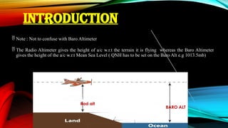
Note :Not to confuse with Baro Altimeter
The Radio Altimeter gives the height of a/c w.r.t the terrain it is flying whereas the Baro Altimeter
gives the height of the a/c w.r.t Mean Sea Level ( QNH has to be set on the Baro Alt e.g 1013.5mb)
Rad alt
BARO ALT
5.
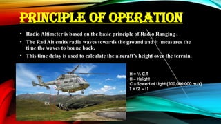
PRINCIPLE OF OPERATION
•Radio Altimeter is based on the basic principle of Radio Ranging .
• The Rad Alt emits radio waves towards the ground and it measures the
time the waves to boune back.
• This time delay is used to calculate the aircraft’s height over the terrain.
H = ½ C.T
H – Height
C – Speed of Light (300,000,000 m/s)
T = t2 – t1
TX
RX
6.
SYSTEM DESCRIPTION –(RAM 703A - IN MPH 10 )
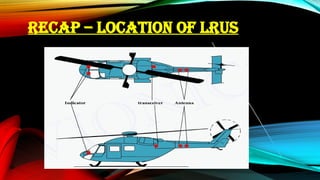
The primary system components of radio altimeter are:
a) Transceiver
b) Antennae (02) (Tx & Rx) – same Pt No & Interchangeable
c) Indicators (02) (Pilot & Co-Pilot) – same Pt No & Interchangeable
IMPORTANT
THE HEIGHT DISPLAYED ON THE INDICATOR IS IN
METERS
7.
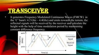
TRANSCEIVER
• It generatesFrequency Modulated Continuous Waves (FMCW) in
the ‘C’ band ( 4.2 Ghz – 4.4Ghz) and emits towards the terrain, the
reflected signals will be received by the receiver and calculate the
height with the help of time modulation period by maintaining
constant difference frequency.
8.
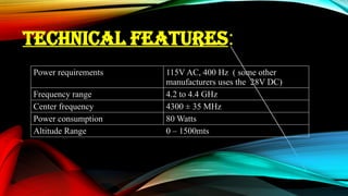
TECHNICAL FEATURES:
Power requirements115V AC, 400 Hz ( some other
manufacturers uses the 28V DC)
Frequency range 4.2 to 4.4 GHz
Center frequency 4300 ± 35 MHz
Power consumption 80 Watts
Altitude Range 0 – 1500mts
10
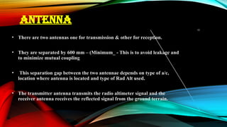
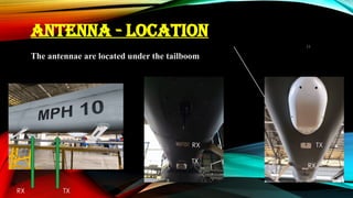
ANTENNA
• There aretwo antennas one for transmission & other for reception.
• They are separated by 600 mm – (Minimum_ - This is to avoid leakage and
to minimize mutual coupling
• This separation gap between the two antennae depends on type of a/c,
location where antenna is located and type of Rad Alt used.
• The transmitter antenna transmits the radio altimeter signal and the
receiver antenna receives the reflected signal from the ground terrain.
INDICATORS
• It facilitatesto read the radio height from the ground to 1500
meters.
• It also facilitates to select the preset decision height and gives a
visual indication of glowing LED lamp, when the aircraft comes
below the preset decision height.
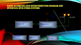
RADIO ALTIMETER LRUSINTERCONNECTION DIAGRAM AND
INTERFACE WITH OTHER SYSTEMS
Tx ANT
TRANSCEIVER
INDICATOR
FDRCVR
Rx ANT
INTERCOM
SYSTEM
115 V AC
From MBB
AFCS
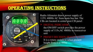
16.
OPERATING INSTRUCTIONS
Radio Altimeterdraws power supply of
115V, 400Hz AC from main bus bar. The
CBs are located in center post CB panel.
DIGITAL INDICATOR:
the ON/OFF switch provides the power
supply of 115v,AC 400Hz to transceiver
unit.
PRESET DECISION HEIGHT KNOB:
It is a rotary switch to select present
height from 0 to 400m.
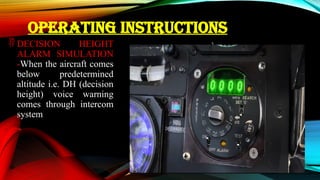
OPERATING INSTRUCTIONS
DECISIONHEIGHT
ALARM SIMULATION
-When the aircraft comes
below predetermined
altitude i.e. DH (decision
height) voice warning
comes through intercom
system
19.
COMMON ERROR
1. Themost common error that causes Rad Alt not to read zero
(0) on ground is that there are objects( cables, trolley etc ) just
below the tailboom thus affecting the accuracy on the indicator.