SlideShare a Scribd company logo
University of South Wales
Final Year Project
Quantifying Extinctions
Author:
Benjamin Rowe
Supervisor:
Dr. Graeme Boswell
April 30, 2015
Abstract
The Red List is a database of all the different species what have been evaluated in terms
of their risk of extinction, the aim of this report is to quantify the risk of extinction to help
supplement the data currently used in the Red List. This project, in particular, focuses
on times to extinction and population distributions using a combination of analytical
mathematics and computer simulations. The Results were also backed up with random
simulation. The results showed that population distributions are not affected by catas-
trophes but times to extinction were heavily reduced with the inclusion of catastrophes,
also the introduction of random error made significant differences. This report suggests
that it is essential to consider catastrophes when classifying the risk of extinction of a
species.
UNIVERSITY OF SOUTH WALES
PRIFYSGOL DE CYMRU
FACULTY OF COMPUTING, ENGINEERING & SCIENCE
SCHOOL OF COMPUTING & MATHEMATICS
STATEMENT OF ORIGINALITY
This is to certify that, except where specific reference is made, the work described in
this project is the result of the investigation carried out by the student, and that neither
this project nor any part of it has been presented, or is currently being submitted in
candidature for any award other than in part for the degree of BSc or BSc with Honours
of the University of South Wales.
Signed .................................................................................... (student)
Date ....................................................................................
(This statement must be bound into each copy of your Project Report.)
1
Acknowledgments
The one person I would like to thank for not just being my project leader, but also
being my tutor in first year and having taught me all three years throughout University
is Dr. Graeme Boswell. He has helped me to reach my potential each year while at the
same time making me work for it and for that I am beyond grateful.
2
Contents
1 Introduction 6
1.1 How Species are Classified [5] . . . . . . . . . . . . . . . . . . . . . . . . 7
1.1.1 Least Concern (LC) . . . . . . . . . . . . . . . . . . . . . . . . . . 8
1.1.2 Near Threatened (NT) . . . . . . . . . . . . . . . . . . . . . . . . 8
1.1.3 Vulnerable (VU) . . . . . . . . . . . . . . . . . . . . . . . . . . . 8
1.1.4 Endangered (EN) . . . . . . . . . . . . . . . . . . . . . . . . . . . 9
1.1.5 Critically Endangered (CR) . . . . . . . . . . . . . . . . . . . . . 10
1.1.6 Extinct in the Wild (EW) . . . . . . . . . . . . . . . . . . . . . . 10
1.1.7 Extinct (EX) . . . . . . . . . . . . . . . . . . . . . . . . . . . . . 11
2 Discrete Time Models 12
2.1 Illustrative Example . . . . . . . . . . . . . . . . . . . . . . . . . . . . . 12
2.1.1 The Initial Problem . . . . . . . . . . . . . . . . . . . . . . . . . . 12
2.1.2 Probability Distributions . . . . . . . . . . . . . . . . . . . . . . . 13
2.1.3 Expected Times to Absorption . . . . . . . . . . . . . . . . . . . . 16
2.2 Application . . . . . . . . . . . . . . . . . . . . . . . . . . . . . . . . . . 18
2.2.1 Birth and Death Rates . . . . . . . . . . . . . . . . . . . . . . . . 18
2.3 Population Distributions without Catastrophes . . . . . . . . . . . . . . . 19
2.3.1 Expected Times to Extinction . . . . . . . . . . . . . . . . . . . . 20
2.4 Discussion . . . . . . . . . . . . . . . . . . . . . . . . . . . . . . . . . . . 25
3 Continuous Time Models: Times to Extinction 26
3
3.1 Expected Time to Extinction . . . . . . . . . . . . . . . . . . . . . . . . 26
3.2 Numerical Solutions . . . . . . . . . . . . . . . . . . . . . . . . . . . . . . 27
3.3 Population Distributions without Catastrophes . . . . . . . . . . . . . . . 29
3.4 Discussion . . . . . . . . . . . . . . . . . . . . . . . . . . . . . . . . . . . 30
4 Continuous Time Models: Catastrophes 31
4.1 Expected Time to Extinction with Catastrophes - Derivation . . . . . . . 31
4.2 Expected Time to Extinction with Catastrophes - Results . . . . . . . . . 33
4.3 Expected Population Distributions . . . . . . . . . . . . . . . . . . . . . 35
4.4 Discussion . . . . . . . . . . . . . . . . . . . . . . . . . . . . . . . . . . . 40
5 Simulation with NetLogo 42
5.1 Code Derivation . . . . . . . . . . . . . . . . . . . . . . . . . . . . . . . . 43
5.2 Results . . . . . . . . . . . . . . . . . . . . . . . . . . . . . . . . . . . . . 44
5.2.1 Expected Times to Extinction . . . . . . . . . . . . . . . . . . . . 44
5.2.2 Population Distribution . . . . . . . . . . . . . . . . . . . . . . . 46
5.3 Discussion . . . . . . . . . . . . . . . . . . . . . . . . . . . . . . . . . . . 46
6 Brownian Motion 48
6.1 Fokker-Planck Equation . . . . . . . . . . . . . . . . . . . . . . . . . . . 48
6.2 Sample Path Equation Derivation . . . . . . . . . . . . . . . . . . . . . . 49
6.3 Numerical Analysis . . . . . . . . . . . . . . . . . . . . . . . . . . . . . . 52
6.4 Discussion . . . . . . . . . . . . . . . . . . . . . . . . . . . . . . . . . . . 55
7 Conclusions 57
A NetLogo Code 63
A.1 Initial Simulation.nlogo . . . . . . . . . . . . . . . . . . . . . . . . . . . . 63
B MatLab Code 68
B.1 Dissertation.m . . . . . . . . . . . . . . . . . . . . . . . . . . . . . . . . . 68
B.2 Binomial.m . . . . . . . . . . . . . . . . . . . . . . . . . . . . . . . . . . 70
4
B.3 Continuum Matrix.m . . . . . . . . . . . . . . . . . . . . . . . . . . . . . 71
C Maple Code 73
C.1 V Graphs.mw . . . . . . . . . . . . . . . . . . . . . . . . . . . . . . . . . 73
5
Chapter 1
Introduction
There have been many extinctions in the world, some more commonly known like the
Dinosaurs or the Dodo, and some less known. A species is not officially classed as extinct
until it has not been seen in the wild for at least 50 years. There are isolated extinctions
(e.g. extinct in Britain but still live in Europe) or mass extinction (very rare), a species
can also be extinct from the wild if it only exists in captivity. A functionally extinct
species is when there are no members of that species population that are capable of re-
producing.
The ’Heath Hen on Martha’s Vineyard’ is a good example, living on the coasts of North
America. It was noted around 1830 that their numbers were starting to rapidly decline
and by 1870 their population was believed to be restricted to Martha’s Vineyard. In the
early 20th century there was only about 50 hens left and in 1908 a sanctuary was created
to try and increase population numbers. In the next 5 years or so the 50 in the beginning
rose to over 2000 but a poultry disease brought from domestic turkeys and only 13 living
heath hens were recorded to be living in 1927. The population never recovered after this
and a couple of natural disasters, the last heath hen, Booming Ben, died in 1932. [4]
The story displays examples of human influence, predators, natural disasters, isolated
extinction and functional extinction.
6
There are many causes for extinction, like starvation, natural disasters/catastrophes,
over hunting, predators or competition, all of which can be objectively modelled mathe-
matically to classify the status of the species, the only problem is coming up with different
definitions on values and expected times to extinction which in itself can be subjective.
Quantifying the risk of these extinctions is important because it helps the human race
to understand a suitable point in time where they should start intervening (i.e. breeding
programs or relocation or to stop the hunting). Without these barriers there would be
many more animals already not in existence, on the other hand sometimes if a popula-
tion is too big it can indirectly affect other species, hence a cull would also come into
action. There is a set of classifications already in place to distinguish how ’well’ a species
is surviving Figure (1.1).
Figure 1.1: Icons to classify status of species population, also known as the red list [1].
These letters stand for (from right to left): Extinct; Extinct in the Wild; Critically En-
dangered; Endangered; Vulnerable; Near Threatened, Least concern; there are two more
classifications where the species at hand hasn’t been evaluated or the data available isn’t
sufficient. [3]
1.1 How Species are Classified [5]
The Red List is a set of criteria that evaluate any species on population numbers if there
is a believed risk of numbers making a significant drop, after assessing the required data
against the criteria the species will then be put into one of the classes. ’Least Concern’
and ’Near Threatened’ there will be almost never any action taken, the next 3 classes
7
action is taken in order to raise numbers with the hope of putting them back into one
of the first two classes. The last two ’Extinct in the Wild’ and ’Extinct’ are extreme
concerns but luckily quite rare.
1.1.1 Least Concern (LC)
This is the lowest level of conservation, species that fall in this category (e.g. humans or
houseflies) have a very widespread population.
1.1.2 Near Threatened (NT)
A near threatened species are likely to fall under a threatened status in the near future.
1.1.3 Vulnerable (VU)
The next few categories are based on 5 different criteria: population reduction rate;
geographic range; population size; population restrictions; and probability of extinction.
An example of a vulnerable species is the ’Snaggletooth Shark’, while its area of occupancy
is massive the rate of reduction in their population numbers is more than 10% in the last
10 years.
To be classed as vulnerable, the population of that species must meet any of the criteria
below:
1. The population has declined between 30-50 percent in the last 10 years or 3 gener-
ations (whichever is longer)
(a) 30% if the cause of the decline is unknown.
(b) 50% if the cause of the population decline is known.
2. The population’s:
(a) ’extent of occurrence’ is less than 20, 000 square kilometres; the extent of
occurrence is the minimum area in which it could contain all the different sites
to which that species lives on.
8
(b) ’area of occurrence’ is less than 2000 square kilometres.
3. If the species has less than 10,000 mature individuals present.
4. If the restriction on the species is less than 1000 mature individuals per 20 square
kilometres.
5. If the probability of extinction is at least 10% in the next 100 years.
1.1.4 Endangered (EN)
An example of an endangered population is the ’Siberian Sturgeon’. Overfishing and
poaching has meant that numbers have declined between 50 and 80 percent in the last
three generations (about 50 years).
A species is classed as endangered if any of the following points are met:
1. The population has been reduced between 50 and 70 percent over the last 10 years
or three generations.
(a) 50% if the cause of population reduction is unknown.
(b) 70% if the cause of loss of population in known.
2. The species has a:
(a) ’Extent of occurrence’ of less than 5,000 kilometres squared.
(b) ’Area of occupancy’ of less than 500 kilometres squared.
3. There are fewer than 2,500 mature individuals. Also the species is classed as en-
dangered if the population has declined more than 20% in the last 5 years (or 2
generations).
4. When the population in one area of occupancy is less than 250 mature individuals,
at this point the extent of occurrence is not considered.
5. If the probability of extinction is more than 20% in the next 20 years or 5 generations
(whichever is longer).
9
1.1.5 Critically Endangered (CR)
An example of a critically endangered species is the Bolivian Chinchilla Rat, this is due
to the fact that its extent of occurrence is even less than 100 square kilometres. The
forests these rodents live in are being cut down to make room for livestock.
To be classed as critically endangered a species has to meet one of the following criteria:
1. Measured over whichever is longer out of 10 years and three generations, if the
population has declined in numbers of at least 90% or 80% if the cause of the
decline is still unknown.
2. If the population’s:
(a) extent of occurrence is less than 100 kilometres squared.
(b) area of occupancy is less than 10 square kilometres.
3. If there are less than 250 mature individuals left.
4. When each of the populations is restricted to just 50 mature individuals.
5. When the probability of extinction is at least 50% in the next 10 years.
1.1.6 Extinct in the Wild (EW)
A species that is extinct in the wild, only exists in cultivation (plants) and captivity
(animals) so for example a closely monitored garden or a zoo. However, a species is only
recorded as EW if there have been no studies to confirm numbers in the wild after a
number of years.
One example of a species that is EW is the Black soft-shell turtle, a small population of
150-300 live in a pond near a place of worship and hence are not allowed to be taken, this
has resulted in no programs to help the populations in the wild or many being found in
zoos around the world.
10
1.1.7 Extinct (EX)
While it is very hard to prove a species is definitely extinct, a species is classified as
extinct when there are no more left in the wild or captivity, normally declared after nu-
merous studies and no reported sightings after an extensive period of time.
The problem at hand is that the criteria ’Probability of Extinction’ is just a percent-
age, and again is based upon a deterministic approach. The aim of this project is to see
if there is a suitable replacement for this criteria that not only gives a time the aver-
age person can understand but also introduces an element of randomness (or noise) that
eventually leads to introducing confidence limits. With all this it would then be possible
to give a level of confidence depending on the set constraints and alter the confidence in-
tervals as needed (e.g. 99% confidence limits will be more widespread about the estimate
than 60% for example).
In this report the problem at hand will be tackled in gradual steps. First the birth
and death rates alone will be considered with a discrete time variable. After Discrete
time has been evaluated a continuum approach will then be investigated where eventu-
ally catastrophe rates will also be included. After these main rates have been included
a stochastic approach is considered as well as a some computer simulations to hopefully
give more evidence from a numerical sense.
11
Chapter 2
Discrete Time Models
Discrete data, while not the most appropriate method, will give data easier to work with
and can be used to make future predictions. Also once the basics are known from the
analysis of this data then applications can be made later on in future chapters.
2.1 Illustrative Example
2.1.1 The Initial Problem
Consider a counter performing an unbiased random walk on a simple number line (Figure
2.1) starting from 0 and going up to 4 is moved. A ’fair’ coin is flipped every minute;
if the coin lands head side up then the counter is moved one position to the right and
to the left if the coin lands tails side up. If a heads is flipped while the counter is on
position 4 then the counter does not move position. The game ends when the counter
reaches position 0.
There are two questions at hand: (1) what is the probability of the counter being at
a particular position at some time t?; and (2) what is the expected time to position 0
from each unique starting point of the counter on the number line?
The fractions labelling the arrows represent the probabilities of moving from each posi-
12
Figure 2.1: An unbiased random walk on {0, 1, 2, 3, 4}.
tion to the next at the end of each minute (Figure 2.1).
2.1.2 Probability Distributions
Suppose, for example, the counter starts off at position 1 at time t = 0. After n minutes
(i.e. n jumps), the position of the counter can be described by a probability distribution
determined from the incidence matrix of the random walk.
P =















1 0.5 0 0 0
0.5 0 0.5 0 0
0 0.5 0 0.5 0
0 0 0.5 0 0.5
0 0 0 0.5 0.5















(2.1)
Note that Pij denotes the probability of moving from position ’j − 1’ to position ’i − 1’
at the end of each minute.
The following vectors Vn represent the probability distribution of the counter being in
that position after n minutes. V0 represents the counter being placed at position 1 to
start the game off.
13
V0 =















0
1
0
0
0















(2.2)
V1 = PV0 =















0.5
0
0.5
0
0















V2 = PV1 = P2
V0 =















0.5
0.25
0
0.25
0















V3 = PV2 = P3
V0 =















0.625
0
0.25
0
0.125















V4 = PV3 = P4
V0 =















0.625
0.125
0
0.1875
0















(2.3)
14
limn→∞
Vn = Pn
V0 =















1
0
0
0
0















(2.4)
This demonstrates that 0 is absorbing, even starting at different positions doesn’t change
the final result; i.e. the initial data doesn’t change the final outcome. This can be proven
with the power method of matrices.
Taking the eigenvalues using MatLab and arranging them into a diagonal matrix D:
P = C−1
DC (2.5)















1 0.5 0 0 0
0 0 0.5 0 0
0 0.5 0 0.5 0
0 0 0.5 0 0.5
0 0 0 0.5 0.5















= C−1















1 0 0 0 0
0 −0.766 0 0 0
0 0 −0.1736 0 0
0 0 0 0.5 0
0 0 0 0 0.9329















C (2.6)
and irrespective of what C is
Pk
= C−1















1 0 0 0 0
0 −0.766 0 0 0
0 0 −0.1736 0 0
0 0 0 0.5 0
0 0 0 0 0.9329















k
C (2.7)
So
lim
k→∞
Pk
= lim
k→∞
C−1
Dk
C (2.8)
15
=















1 0 0 0 0
0 0 0 0 0
0 0 0 0 0
0 0 0 0 0
0 0 0 0 0















(2.9)
And so because only that one value remains for high values of k this demonstrates that
state 0 is an absorbing state, this could have also been demonstrated from:
λ =















1
0
0
0
0















(2.10)
2.1.3 Expected Times to Absorption
In the previous section it was seen that 0 was an absorbing state; irrespective of the
starting position, the counter would always end up at 0. The only difference made by the
starting state is the time taken to reach 0. Using an approach similar to the above, it is
possible to calculate this expected time.
Let E[J] denote the expected time for the random walk starting from position J to
reach position 0. Consider the counter starting at position 1. After 1 minute with prob-
ability a half the counter moves to the right and then the expected time changes to the
expected time from position 2 but with probability 1
2
the counter can go left to position
0 and at which point the random walk has reached the absorbing state. I.e.:
E[1] = 1 +
1
2
E[2] +
1
2
E[0] (2.11)
and since E[0] = 0
16
E[1] = 1 +
1
2
E[2]
Other states are defined similarly:
E[2] = 1 +
1
2
E[1] +
1
2
E[3]
E[3] = 1 +
1
2
E[2] +
1
2
E[4]
E[4] = 1 +
1
2
E[3] +
1
2
E[4]
Rearranging these:
E[1] −
1
2
E[2] = 1
−
1
2
E[1] + E[2] −
1
2
E[3] = 1
−
1
2
E[2] + E[3] −
1
2
E[4] = 1
−
1
2
E[3] +
1
2
E[4] = 1 (2.12)
which can easily be represented in matrix form as











1 −1
2
0 0
−1
2
1 −1
2
0
0 −1
2
1 −1
2
0 0 −1
2
1
2






















E[1]
E[2]
E[3]
E[4]











=











1
1
1
1











(2.13)
Notice the expected times of Equation 2.6 are of the form: BE = C where B and C are
known. Then E an be obtained by multiplying both sides by B−1
to get:
E = B−1
C (2.14)
Using MatLab:
E = B−1
C =











2 2 2 2
2 4 4 4
2 4 6 6
2 4 6 8






















1
1
1
1











=











8
14
18
20











(2.15)
17
So the expected times to reach state zero starting from the different states are:
E[1] = 8 minutes
E[2] = 14 minutes
E[3] = 18 minutes
E[4] = 20 minutes (2.16)
2.2 Application
If we were to assign the position number in the above illustrative example to the number
of females in a population at time t (which could be in days, weeks, or even years) then
moving to the left corresponds to one female dying and moving to the right corresponds
to the birth of another female. This is the most extreme simple case possible as it only
allows for one to die or be born each time step which is very unrealistic, also that the
probabilities are equal in that they are both one half.
To further increase the accuracy multiple births and multiple deaths alongside each other
could be considered (although it is unnecessary). We will first consider the population
details.
2.2.1 Birth and Death Rates
In this model we are going to assume that the probability of moving right from position
j is Rj and moving to the left is Qj, so Rj is the probability that there is a birth when
there are j members of the population, and Qj is the probability of a death when there
are j members. Suppose
Rj = bj
Qj = dj2
(2.17)
where b and d are small and which is in keeping with the logistic model of population
growth. Further suppose there is a maximum population (K) where RK = 0.
18
2.3 Population Distributions without Catastrophes
Consider a Markov chain representing a population where the states correspond to the
number of individuals. As the population’s extinct in state zero it is not included. This
Markov chain is represented in Figure 2.2 and Figure 2.3. ’b(2)’ represents the probability
of a birth from state 2 and ’d(2)’ therefore represents the probability of a death from state
2.
Looking at these and assuming that the system is in balance (i.e. the number leaving
Figure 2.2: Markov Chains representing system of births and deaths where K = 3.
Figure 2.3: Markov Chains representing system of births and deaths where K = 4.
a state is matched by what’s entering it), it is then possible to use these probabilities to
estimate the probability distribution of the population.
About state 1:
P(1)b(1) = P(2)d(2)
P(1) =
P(2)d(2)
b(1)
(2.18)
About state 2:
P(1)b(1) + P(3)d(3) = P(2)[d(2) + b(2)]
19
P(2)d(2) + P(3)d(3) = P(2)[d(2) + b(2)]
P(3)d(3) = P(2)b(2)
P(2) =
P(3)d(3)
b(3)
(2.19)
About state 3:
P(2)b(2) + P(4)d(4) = P(3)[b(3) + d(3)]
P(3)d(3) + P(4)d(4) = P(3)[b(3) + d(3)]
P(4)d(4) = P(3)b(3)
P(3) =
P(4)d(4)
b(3)
(2.20)
From here a pattern has started emerging, and so in a general form:
P(a) =
P(a + 1)d(a + 1)
b(a)
∀1 ≤ a ≤ K − 1 (2.21)
The first step of using this equation is to estimate a value for P(K) and apply Equation
(2.21) iteratively to calculate P(1)...P(K). Then if:
K
i=1
P(i) = 1 (2.22)
A second iteration is needed but this time set
P(K) =
estimated P(K)
K
i=1 P(i)
(2.23)
to ensure the sum of probabilities of being at each state all add up to equal 1, this makes
sure P(i) is now a genuine probability distribution.
This approach can be very time consuming, especially with larger values of K, so a
MatLab code was produced in order to do this efficiently and quickly (see Appendix B.2.
This created Figures 2.4, 2.5 and 2.6.
2.3.1 Expected Times to Extinction
Given the illustrative example seen when calculating the expected times to absorption,
it is clear that the population will become extinct eventually. However, it is possible to
20
Figure 2.4: Distribution Graphs found by solving Equation (2.21) with K = 10.
Figure 2.5: Distribution Graphs found by solving Equation (2.21) with K = 10.
determine the probability distribution of the population before its extinction via a simple
argument based on movements between states.
Like before, assuming that only one event can occur in any one time step but now
using more realistic probabilities for births and deaths we end up with a similar matrix
21
Figure 2.6: Distribution Graphs found by solving Equation (2.21) with K = 10.
formation as before in Equation (2.13).











1 −bj 0 · · · 0
−dj2
1 −bj · · · 0
· · · −dj2
1 −bj · · ·
0 0 −dj2
1 · · ·


























E[1]
E[2]
E[3]
· · ·
E[j = n]















=















1
1
1
· · ·
1















(2.24)
This work is based on a paper by B. J. Cairns and P. K. Pollett [6] where matrix manip-
ulation is used to calculate expectancy rates.
Where Equation (2.24) is a symmetrical matrix. From here this can be rearranged and
solved for the expected times to extinction, for discrete data, can be calculated in the
form of...















E[1]
E[2]
E[3]
· · ·
E[j = n]















=











1 −bj 0 · · · 0
−dj2
1 −bj · · · 0
· · · −dj2
1 −bj · · ·
0 0 −dj2
1 · · ·











−1















1
1
1
· · ·
1















(2.25)
22
With Figures 2.7, 2.8 and 2.9, these display what would be the expected times to extinc-
Figure 2.7: Times to Extinction from state j found by using Equation (2.25).
Figure 2.8: Times to Extinction from state j found by using Equation (2.25).
tion in unit time when the target population is currently in state j. The main problem
straight away is that it is oscillating around the zero (or extinct) level, in practice it
would be assumed that once it reaches 0 it will stay at zero and not just simply go from
being extinct to being alive again.
23
Figure 2.9: Times to Extinction from state j found by using Equation (2.25).
In the cases previously looked at K has been the cap on the population (or more applied
could be a fixed carrying capacity), from this and looking at the distributions it is possi-
ble to find the state that the population is most likely to be in (Figures 2.4..2.6 suggests
all three to be around 5 or 6) and then use the expected time for that state from Figures
2.7, 2.8 and 2.9 to estimate a time until extinction (again, in unit time). So some of the
results from the graphs in Figures 2.7..2.9 are below:
E[K] = −20.2348 (2.26)
E[µ] = 9.4228 When K = 10 (2.27)
E[K] = 903.6297 (2.28)
E[µ] = −49.9629 When K = 15 (2.29)
E[K] = 886.8743 (2.30)
E[µ] = 0.3738 When K = 20 (2.31)
24
In the results above, µ is the mean number in the population with an upper boundary
(cap) of K. This mean number was drawn from Figure 2.4.
These values where results from using Equation (2.25) with b = 0.1, and d = 0.02,
and are also measured in unit time.
2.4 Discussion
The first problem with the above is that for values of K under 20 it fails to produce
a realistic result, in that they are all negative and this makes no sense when it comes
to approximating times to extinction. These results are most likely due to the fact that
a discrete time step has been used and isn’t an accurate enough measure for what we need.
Another problem may arise with respect to the fact that a discrete set of data was
used against distribution graphs that are based on a continuum approach.
25
Chapter 3
Continuous Time Models: Times to
Extinction
In Chapter 2 time was modelled in discrete steps/chunks, the problem at hand is what
if multiple events could happen in each time step and hence a continuum approach is
required.
3.1 Expected Time to Extinction
Suppose time (t) is now continuous, where ∆t is sufficiently small, and there can be a
number of different events including: a birth; a death; or nothing happens at any point.
At this stage with a current population ’j’, let E[j] denote the expected time to extinc-
tion from j, b(k) and d(j) are also the birth and death rates.
So it can be modelled that the expected time to extinction is after a period of time
either a birth happens and the expected time to extinction is now E[j + 1], a death
happens and the expected time to extinction is now E[j −1], or nothing happens and the
expected time to extinction stays the same. In mathematical terms it can be represented
by:
26
E[j] = ∆t + b(j)∆tE[j + 1] + d(j)∆tE[j − 1] + (1 − b(j) − d(j))∆tE[j] (3.1)
0 = ∆t + b(j)∆tE[j + 1] + d(j)∆tE[j − 1] − (b(j) + d(j))∆tE[j] (3.2)
Then divide by ∆t and rearrange
−1 = b(j)E[j + 1] + d(j)E[j − 1] − (b(j) + d(j))E[j] (3.3)
Putting this last equation into matrix form makes it possible to solve in a similar manner
to the previous chapter for E. Then putting a ’cap’ on the system (k) so that b(K) = 0
ensures there is a finite number of equations when E[0] = 0.
k
j=0
= 1 (3.4)
3.2 Numerical Solutions
Putting Equation (3.3) into matrix form and solving for all E[j] with 1 ≤ j ≤ K gives
you Figures 3.1, 3.2 and 3.3. Using the data from Figures 3.1, 3.2 and 3.3 and their
corresponding distribution graphs in Figures 2.4, 2.5 and 2.6 some values can be found
for the expected time to extinction with a carrying capacity of K.
Using a similar approach as in the previous chapter, in matrix form it can be repre-
sented as:















E[1]
E[2]
E[3]
· · ·
E[j = K]















=











−bj − dj2
bj 0 · · · 0
dj2
−bj − dj2
bj · · · 0
· · · dj2
−bj − dj2
bj · · ·
0 0 dj2
−bj − dj2
· · ·











−1















−1
−1
−1
· · ·
−1















(3.5)
Looking at Figures 2.4, 2.5 and 2.6, the value of µ (where µ is the average number of
mature individuals in the population) was found by looking for the highest value in the
27
graphs and then comparing this value of µ with Figures 3.1, 3.2 and 3.3 then respectively
to get the expected times to extinction.
E[K] = 487.3401
E[µ] = 479.5891 when K = 10
E[K] = 492.6602
E[µ] = 481.9846 when K = 15
E[K] = 493.8111
E[µ] = 481.9932 when K = 20 (3.6)
Looking at these values it is noticeable that the numbers increase slower and slower, this
is unlike what happened in Chapter 2 where as K increased the values of the graph shot
up to very large values very quickly. Figures 3.1, 3.2, and 3.3 were solved using B.1.
Figure 3.1: Graphs showing the expected times to extinction found by solving Equations
(3.3) and (3.4) with b = 0.1, d = 0.02 and K = 10.
28
Figure 3.2: Graphs showing the expected times to extinction found by solving Equations
(3.3) and (3.4) with b = 0.1, d = 0.02 and K = 15.
Figure 3.3: Graphs showing the expected times to extinction found by solving Equations
(3.3) and (3.4) with b = 0.1, d = 0.02 and K = 20.
3.3 Population Distributions without Catastrophes
Assuming if the value of time ∆t was made small enough then the Markov chains used
in Section 2.3 would be exactly the same and hence the same equations and distribution
29
graphs would be this result. The same graphs are produced also because there are no
catastrophes included at the moment meaning no extra variables have been included.
3.4 Discussion
So using continuous data and assuming ∆t to be small enough results in a completely
different expected times graph compared to when discrete data was used, although the
population distribution remains unchanged. With the work done in this chapter, a new
set of expected times (E[µ]) in Equation 3.6.
Now compared to Chapter 2, both the expected times graphs and distribution graphs
are both based on continuous data and the results all make a lot more sense. In Figures
3.1, 3.2, and 3.3 all the times to extinction are now positive and the curves in the graphs
make a lot more sense. The shape of these graphs are more realistic because when the
numbers of mature individuals starts to diminish the expected times drop significantly,
and as the numbers start to thrive the times increase slower and slower (i.e. as population
numbers → K, the gradient of the graph → 0).
Remembering back with the example of the Heath Hen of Martha’s Vineyard in Chapter
1, there were many examples of natural disasters (or even man-made disasters) which
will be referred to in this report as catastrophes. The next Chapter looks into these
catastrophe rates alongside the continuum approach and on top of the birth and death
rates. After finding new solutions we can compare the population distributions and ex-
pected times to extinction where catastrophes weren’t present. Catastrophes are relevant
in this work mainly because so far during each small time period only one death/birth
has occurred, this will now look into multiple occasions in each unit time.
30
Chapter 4
Continuous Time Models:
Catastrophes
In Chapter 3 while a continuum approach was considered, only a maximum of one death/
birth in each unit time was permitted. In chapter 4 catastrophes are going to be consid-
ered alongside several deaths at the same time too, however for simplicity at the moment
only a maximum of one birth is allowed in each unit time.
We are looking mainly into catastrophes to add an element of randomness to the es-
timated time to extinction that was discussed in the introduction, at the moment the
probability to extinction is just a percentage so the aim here is to create a more accu-
rate estimate and maybe add some confidence limits (or noise) to what is believed to be
correct.
4.1 Expected Time to Extinction with Catastrophes
- Derivation
In Chapter 3 a system of equations were created (Equation (3.3)) assuming there were a
single birth, a single death or no population change over a small time interval. Looking
31
back to Equation (3.1) we had:
E[j] = ∆t + b(j)∆tE[j + 1] + d(j)∆tE[j − 1] + (1 − b(j)∆t − d(j)∆t)E[j] (4.1)
From here to change it from a deterministic approach to a stochastic one we need to add
an element of catastrophe, hence:
E[j] = ∆t + b(j)∆tE[j + 1] + d(j)∆tE[j − 1] + (1 − b(j)∆t − d(j)∆t)E[j]
+ ∆t
a
i=1
(
K
j=a+1
P(j)q(i|j))b(a) (4.2)
Next Equation (4.2) needs to be rearranged to be able to work with it.
0 = ∆t + b(j)∆tE[j + 1] + d(j)∆tE[j − 1] − (b(j)∆t + d(j)∆t)E[j]
+ ∆t
a
i=1
(
K
j=a+1
P(j)q(i|j))b(a)
0 = 1 + b(j)E[j + 1] + d(j)E[j − 1] − (b(j) + d(j))E[j] +
a
i=1
(
K
j=a+1
P(j)q(i|j))b(a)
−1 = b(j)E[j + 1] + d(j)E[j − 1] − (b(j) + d(j))E[j] +
a
i=1
(
K
j=a+1
P(j)q(i|j))b(a)
(4.3)
Which can now be arranged into matrix form where,
M = BE
E = B−1
M (4.4)
Where...
E =















E[1]
E[2]
E[3]
· · ·
E[K]















, M =















−1
−1
−1
· · ·
−1















(4.5)
B =











−b(1) − d(1)2
b(1) · · · 0
d(1)2
+ q(1|2) −b(2) − d(2)2
b(2) · · ·
· · · d(2)2
+ q(2|3) −b(3) − d(3)2
b(3)
q(i|K) · · · d(K − 1)2
+ q(K − 1|K) −b(K) − d(K)2











(4.6)
32
At this point it should be explained that q(i|j) is the catastrophe term included in the
matrix, where q is the probability that a catastrophe occurs and the (i—j) is related back
to the binomial distribution where:
q(i|j) = q



j
i


 pj−i
(1 − p)i
(4.7)
j is the number of individuals present when the catastrophe occurs, i is the number of
individuals left after the catastrophe has happened and p is the probability that each
individual dies when the catastrophe happens.
In Equation (4.6) ’i’ corresponds to the column number and ’j’ holds the same value
as the row number of the position it holds in the matrix. Anything below, and not in-
cluding, the subdiagonal is just the catastrophe term and does not hold any death terms.
All values above, and not including, the superdiagonal are just equal to zero.
4.2 Expected Time to Extinction with Catastrophes
- Results
The main difference in the equations considering catastrophes compared to the case with
no catastrophes (Chapter 3) was the inclusion of the entries in the matrix below the
diagonal. Solved using MatLab and the code in Appendix B.1 the q term can be set to
zero to eliminate any catastrophes. The presence of these terms can cause a significant
difference in the expected times to extinction from each state, as seen in Figures 4.1, 4.2
and 4.3.
With more of a chance of dying due to catastrophes this would make a lot of sense
that the times have reduced considerably. Comparing some of the values between with
catastrophes and without catastrophes there is a difference of around 120 between equiv-
alent states, also considering that the probability of a catastrophe occurring is only one
in a thousand this could drastically decrease expected times to extinction further if this
33
Table 4.1: Table comparing catastrophe (q) and catastrophe-death (p) rates with the
average expected time to extinction over 20 simulations
p 0.001 0.5 0.001 0.1 0
q 0.2 0.2 1 0.7 -
Av. 152.667 15.333 90.853 27.417 149.5
value was even slightly increased.
In Table 4.2 there is 5 different combinations of values for p and q and below is the aver-
age time to extinction when these values were put into NetLogo (a stochastic simulation
program). The average can be assumed to be a number of small time intervals, more will
be discussed on NetLogo in the next chapter. Figures 4.1, 4.2 and 4.3 were plotted using
Appendix B.3 in MatLab.
Figure 4.1: Graphs showing the expected times to extinction found by solving Equation
(4.6) with b = 0.1, d = 0.02, q = 0.001, and K = 10.
34
Figure 4.2: Graphs showing the expected times to extinction found by solving Equation
(4.6) with b = 0.1, d = 0.02, q = 0.001, and K = 15.
Figure 4.3: Graphs showing the expected times to extinction found by solving Equation
(4.6) with b = 0.1, d = 0.02, q = 0.001, and K = 20.
4.3 Expected Population Distributions
The expected times to extinction alone aren’t of much use, even though a carrying capac-
ity may have been set it is still unknown where the population’s average state is found
35
below this, if the birth rates are high enough then the population will be close to the
K value. If the population’s catastrophe and or death rates are high enough the system
may hang around the lower valued states.
Taking the same approach as last time by just trying to come up with a set of simulta-
neous equations proven itself very ’fiddly’ and difficult so another approach is required,
we first consider a population that can consist of at most 3 individuals (i.e. the Markov
chain has 3 states). This system is seen in Figure 4.4.
From here, seeing as the population is bounded by 3, we see that P(1) + P(2) +
Figure 4.4: Markov Chains representing system of births, deaths and catastrophes where
K = 3.
Figure 4.5: Markov Chains representing system of births, deaths and catastrophes where
K = 4.
P(3) = 1 in a state of equilibrium where P(j) is the probability there are j individuals in
36
Figure 4.6: Markov Chains representing system of births, deaths and catastrophes where
K = 5.
the population. Setting these probabilities equal to each other and re-arranging gives:
About state 1:
P(1)b(1) = P(2)d(2) + P(2)q(1|2) + P(3)q(1|3)
P(1) =
P(2)[d(2) + q(1|2)] + P(3)q(1|3)
b(1)
(4.8)
About state 2
P(2)[b(2) + d(2) + q(1|2)] = P(1)b(1) + P(3)[d(3) + q(2|3)]
= P(2)[d(2) + q(1|2)] + P(3)[d(3) + q(1|3) + q(2|3)]
P(2)[b(2) + d(2) − d(2) + q(1|2) − q(1|2)] = P(3)[d(3) + q(1|3) + q(2|3)]
P(2)[b(2)] = P(3)[d(3) + q(1|3) + q(2|3)]
P(2) =
P(3)[d(3) + q(1|3) + q(2|3)]
b(2)
(4.9)
About state 3
P(3)[d(3) + q(2|3) + q(1|3)] = P(2)b(2)
= P(3)[d(3) + q(1|3) + q(2|3)]
P(3)d(3) = P(3)d(3) (4.10)
From this result it shows that the value of P(3) determines the value of P(1) and P(2).
However as stated before,
n
i=1
P(i) = 1 (4.11)
37
where n is the cap value of the system. With this data a value of P(3) can be chosen
to ensure that P(1) + P(2) + P(3) = 1. In practice an estimated value of P(3) is first
selected and if equation 4.4 does not equal 0 then,
P(n) =
estimated P(n)
n
i=1 P(i)
(4.12)
After this second part of the algorithm then the values are final, however a check to make
sure Equation (4.11) is now satisfied is always preferred.
Now consider the case with a population comprising of at most 4 individuals (Figure
4.5).
About state 1:
P(1)b(1) = P(2)[d(2) + q(1|2)] + P(3)q(1|3) + P(4)q(1|4)
P(1) =
P(2)d(2) + 4
i=2 P(i)q(1|i)
b(1)
(4.13)
About state 2
P(1)b(1) + P(3)[d(3) + q(2|3)] + P(4)q(2|4)
= P(2)[d(2) + q(1|2) + b(2)]
= P(2)[d(2) + q(1|2)] +
4
i=3
P(i)q(1|i)
+ P(3)d(3) + P(3)q(2|3) + P(4)q(2|4)
= P(3)d(3) +
4
i=3
P(i)q(1|i) +
4
i=3
P(i)q(2|i)
P(2) =
P(3)d(3) + 4
i=3 P(i)q(1|i) + 4
i=3 P(i)q(2|i)
b(2)
=
P(3)d(3) + 4
i=3[P(i)q(1|i) + P(i)q(2|i)]
b(2)
(4.14)
About state 3
P(2)b(2) + P(4)d(4) + P(4)q(3|4) = P(3)[d(3) + b(3) + q(1|3) + q(2|3)]
P(3)d(3) +
4
i=3
[P(i)q(1|i) + P(i)q(2|i)] + P(4)d(4) + P(4)q(3|4)
38
= P(3)d(3) + P(3)b(3) + P(3)q(1|3) + P(3)q(2|3)
P(3)b(3) = P(4)q(1|4) + P(4)q(2|4) + P(4)d(4) + P(4)q(3|4)
P(3) = P(4)
3
i=1[q(i|4)] + d(4)
b(3)
(4.15)
About state 4
P(3)b(3) = P(4)[d(4) +
3
i=1
q(i|4)]
P(4) = P(4) (4.16)
A similar rule to above can be used to calculate these probabilities. At this point a
pattern is starting to emerge but is still not absolutely certain, hence a five state Markov
Chain was also needed to hopefully create a general case.
About state 1:
P(1)b(1) = P(2)d(2) +
5
j=2
P(j)q(1|j)
P(1) =
P(2)d(2) + 5
j=2 P(j)q(1|j)
b(1)
(4.17)
About state 2
P(2)[d(2) + b(2) + q(1|2)] = P(1)b(1) + P(3)d(3) +
5
j=3
P(j)q(2|j)
= P(2)d(2) +
5
j=3
[P(j)q(1|j)] + P(3)d(3)
+
5
j=3
[P(j)q(2|j)
P(2) =
5
j=3[P(j)q(1|j)] + P(3)d(3) + 5
j=3[P(j)q(2|j)
b(2)
=
P(3)d(3) + 2
i=1( 5
j=3[P(j)q(i|j)])
b(2)
(4.18)
About state 3
P(3)[d(3) + b(3) +
2
i=1
q(i|3)] = P(2)b(2) + P(4)d(4) +
5
j=4
[P(j)q(3|j)]
= P(3)d(3) +
2
i=1
(
5
j=3
[P(j)q(i|j)]) +
5
j=4
[P(j)q(3|j)]
39
P(3)b(3) =
3
i=1
(
5
j=4
[P(j)q(i|j)]) + P(4)d(4)
P(3) =
P(4)d(4) + 3
i=1( 5
j=4[P(j)q(i|j)])
b(3)
(4.19)
About state 4
P(4)[d(4) + b(4) +
3
i=1
q(i|4)] = P(3)b(3) + P(5)d(5) + P(5)q(4|5)
= P(4)d(4) +
3
i=1
(
5
j=4
[P(j)q(i|j)]) + P(5)d(5)
+ P(5)q(4|5)
P(4)b(4) =
4
i=1
(
5
j=5
[P(j)q(i|j)]) + P(5)d(5)
P(4) =
P(5)d(5) + 4
i=1( 5
j=5 P(j)q(i|j))
b(4)
(4.20)
In general form
P(a) =
P(a + 1)d(a + 1) + a
i=1( K
j=a+1 P(j)q(i|j))
b(a)
(4.21)
Where i is less than j and K is the population cap.
Notice how similar Equation (4.21) is to Equation (2.21) except for the fact that Equa-
tion (4.21) has the summation on the top of the fraction relation to catastrophes, hence
if q = 0 then the two are the same equation effectively.
Solving Equation (4.21) using Appendix B.1 in MatLab, the results are Figures 2.4,
2.5 and 2.6 which is an extremely interesting result.
4.4 Discussion
In this chapter it has been shown that the use of catastrophes does not change the pop-
ulation distribution in any shape or form but has massive effects on the expected times
40
to extinction. The distributions not changing does make logical sense if the randomness
term follows normal characteristics of an error term, in that the average of a series of error
terms is zero, however with very large terms it may be seen that the standard deviation
may change ever so slightly (or else if the value of q was dramatically increased). The
expected times to extinction significantly dropping could be expected too because there
is a higher chance of dying and over several hundred time intervals these probabilities
add up eventually having a noticeable effect of the resultant graphs of times to extinction.
Now that a general form including catastrophes has been derived assuming a continuum
approach, the next step is to make sure the work done so far in this report is accurate.
The next Chapter looks into computer simulation to hopefully back up any calculations
done so far.
41
Chapter 5
Simulation with NetLogo
NetLogo is a computer simulation program that has a stochastic component which can
simulate some of the models created in previous chapters; namely the times to extinction
and population distributions. The results will then be linked to previous results and
compared to see if they back up any of the derivations.
The code created is located in Appendix A. Below in Figure 5.1 is a screenshot showing
NetLogo in the middle of a simulation.
In Figure 5.1, the big black square is where the simulation running is visible (wasn’t
needed for this), on the left of that is a load of sliders which alter the variables mentioned
before as: b; ; q; p; K. Below the sliders are just a few monitors to assess numbers at
any given time interval and on the right of everything else is a line graph plotting the
number of ’turtles’ currently in the system (i.e. state j at time t).
Time in NetLogo is measured as ’ticks’, this can be treated as a dummy variable and just
be considered as one time interval, i.e. assume to be a very small amount of real time.
42
Figure 5.1: A screenshot of NetLogo running a simulation in order to collect random data
with preset variables.
5.1 Code Derivation
In the procedure ’to birth’ the population had to be checked at every tick to make sure
its numbers weren’t over the cap before asking the turtles if they was going to reproduce
or not, the random float had to be to three decimal points because the catastrophe rate
is every 1 in a thousand and this kept numbers similar throughout the program, if the
population was below the cap (previously referred to as ’K’) then the turtles were asked
if they would reproduce and then each turtle was also asked individually.
The ’to death’ procedure works in the same way as birth but there was no check to
make sure the population was below the cap, in the ’to go’ procedure it checks the popu-
lation isn’t extinct before performing this procedure so no additional checks were needed
at all.
The procedure starting ’to catastrophe’ is two procedures in one. First, each turtle
is asked if a catastrophe has happened and the chance of the catastrophe occurring is
determined with a slider. Secondly, if there is a catastrophe then there is a chance that
the turtles dies. The procedure happens in this order to make sure that this elevated
43
death rate only occurs when a catastrophe has actually happened.
The last three procedures all act together to create a list of the total count of turtles
at the end of each tick and then create an external file where this data is saved for use
with other programs such as ’IBM SPSS Statistics 22’, which was used to create the
Histogram 5.2 (this will be discussed later).
5.2 Results
As with the rest of the project, not only have estimated times to extinction been included
but a population distribution is also needed to accurately estimate when there is a cap
on the population.
5.2.1 Expected Times to Extinction
The table 5.2.1 displays the settings the simulation started off with each time and the
results are on the right side of the double vertical line. All values on the left of the double
vertical line are probabilities.
The ’Birth’ column represents the probability that a turtles reproduces with each tick (a
tick is considered a small amount of discrete time in this case). The ’Death’ column is the
probability that each turtles dies within each tick, the ’Catas.’ column is the probability
that a catastrophe happens at each tick. The ’Catas. D.’ column is the probability that
the turtles dies given that there is a catastrophe happening in that tick. The ’Cap’ is the
population cap, it is used to create the initial amount of turtles along-side ’In. Dens.’
(initial density) and the population can never exceed the cap as long as it isn’t altered.
The ’Av. Turts.’ (average turtles) is the average turtles present at each tick over 50
separate simulations. The ’Mean’ is the average time to extinction over 50 individual
simulations and the ’Sta. Dev.’ is the average standard deviation over 50 simulations.
44
Table 5.1: Table of Simulation Slider Settings and Results
Birth Death Catas. Catas. D. Cap In. Dens. Av. Turts. Mean Sta. Dev.
0.1 0.02 0.001 0.2 10 0.5 2 132.2115385 118.1651116
0.5 0.02 0.001 0.2 10 0.5 3 4554.173077 3847.983966
0.1 0.1 0.001 0.2 10 0.5 1 13.01923077 10.92665456
0.1 0.02 0.4 0.2 10 0.5 3 21.82692308 19.36615316
0.1 0.02 0.001 1 10 0.5 1 114.2884615 94.70083681
0.1 0.02 0.001 0.2 20 1 2 161.4807692 120.576148
0.1 0.02 0.001 0.2 10 0.25 2 101.4615385 100.6339633
0.1 0.02 0 0.2 10 0.5 2 149.2307692 124.3965221
The top set of data is the standard set of data to which the rest of the sets of data will
be compared to, this is also the same data that was used to derive the Markov chains
and equations graphs in previous chapters when the cap (K) was equal to ten.
The second set of data has an increased probability of birth and while it was expected
that the mean survival time would increase, the size of increase is surprising, where the
chances of birth is 500% the mean has risen over 10 times what it was before.
The third data set sees an increase in the probability of death and has the expected
result of decreasing the expected time to extinction.
This fourth set of data is key to what this project is looking in to, here there is a massive
increase in the probability that a catastrophe occurs and it has drastically decreased the
expected time to extinction. The results at this stage have back up further any work
done in previous chapters as well as backing up a common sense approach.
45
The sixth set of data, a couple of variables have changed but between the two the only
difference is that the simulation starts of with 20 turtles instead of 10, this increased the
mean a little bit but not by a lot. This result may be linked to the graphs previously
produced of expected times to extinction where as the numbers approached the cap the
expected time to extinction had very little change. Also, comparing the average turtles
to the cap, the average number of turtles rarely gets anywhere near close to the cap which
may explain the very small increases in time as the population reaches its maximum.
Again the penultimate data set is playing with the number of turtles starting the simu-
lation off, and again desired effect but nothing extraordinary.
The last data set is also very interesting as it investigates Chapter 3 where there was
no catastrophes present but the expected times to extinction didn’t jump as much as
hypothesised when generalising from previous findings.
5.2.2 Population Distribution
To create a population distribution a list at the end of each simulation was created where
the number of turtles was recorded at the end of each tick and then SPSS was used to
create the Histogram 5.2. This histogram was created with the 50 simulations of the
original data set and even though the cap is 10, looking at the diagram it is possible to
see that the population never even reached 5.
5.3 Discussion
So now there are some numerical values which solidify the results so far in previous chap-
ters. It has been shown that including catastrophes does not have much effect in terms of
average turtles present at any time interval t. However, including catastrophes does have
a noticeably significant difference on average times to extinction of the population as a
46
Figure 5.2: Poisson Distribution Histogram Using Data from NetLogo. Data collected
when K=20, d=0.02, b=0.2, q=0.001, p=0.2 and starting population is also 20.
whole. With NetLogo it has also been possible to demonstrate how much catastrophe
rates and birth/death rates have as an effect on the system without having to do scientific
study in real life.
While these simulations have been a very good numerical display of the report’s re-
sults so far, looking into Appendix A it is possible to see that there is several elements
of randomness. Chapter 6 looks into the possible effects of random errors and tries to
analyse them in a way that a random path can then be predicted if the different rates
and variables are previously known.
47
Chapter 6
Brownian Motion
Brownian motion is used to turn discrete data into continuous data that still includes a
random error terms which can then be differentiated and integrated etc. to be analysed
on a more general basis.
6.1 Fokker-Planck Equation
Using a similar approach to that of D. Ludwig [2] by tarting off with a deterministic
equation:
dx
dt
= b(x)
dx = b(x)dt (6.1)
From here a random error term is needed to analyse any random events in the natural
world, hence adding to Equation (6.1):
dx = b(x)dt + εa(x)dW (6.2)
The above equation is known as the Ito Equation where epsilon is small. If there is no
noise then a(x) = 0 and the term introducing the random error disappears and it just
returns to a deterministic approach like in Equation (6.1). Also given that X(t)=x,
b(x) = lim
t→0
1
∆t
E[X(t + ∆t) − X(t)]
εa(x) = lim
t→0
1
∆t
E[(x(t + ∆t) − X(t))2
] (6.3)
48
If X was plotted against t as t was increased along the horizontal axis using Equation
(6.1) then the graph would jump in discrete steps. Let v be equal to the sample path of
these graphs and treat it as continuous for all t then using Equations (6.2) ... (6.3),
δv
δt
=
ε
2
δ2
δx2
(a(x)v) −
δ
δx
(b(x)v) (6.4)
Equation 6.4 is known as the Fokker-Planck Equation.
6.2 Sample Path Equation Derivation
Starting off with the logistic equation (Equation 6.5):
dx
dt
= rx 1 −
x
K
(6.5)
From here a substitution is made where t = rτ
K
→ 1
τ
= r
tK
. Then it follows,
d
dτ
=
r
K
d
dt
(6.6)
Then subbing Equation (6.6) back in to Equation (6.5) then follows,
r
K
dx
dt
= rx 1 −
x
K
1
K
dx
dt
=
x
K
(K − x)
˙x = x(K − x) (6.7)
With this done, it is still currently a deterministic equation so an element of noise is
added. Since x and t are parametres that we cannot alter,
K = 1 +
√ dW
dt
(6.8)
From here, substituting Equation 6.8 back into Equation (6.7) then it follows:
˙x = x 1 +
√ dW
dt
− x
dx
dt
= x + x
√ dW
dt
− x2
= x(1 − x) + x
√ dW
dt
dx = x(1 − x)dt + x
√
dW (6.9)
49
Where W is a sample path function including normalised Brownian Motion. Now com-
paring Equations (6.4) and (6.9) we get:
dtv =
2
d2
x(x2
v) − dx(x[1 − x]v) (6.10)
By setting dtv = 0 and w = x2
v in Equation (6.10) and then integrating the following
happens:
0 =
2
d2
x(w) − dx(x[1 − x]v)
0dx =
2
wxxdx −
d
dx
(x[1 − x]v)dx
0 =
2
wx − x(1 − x)v
=
2
wx − xv − w
=
2
wx −
w
x
− w
=
2
wx −
1 − x
x
w (6.11)
Now re-arranging and integrating for a second time it follows:
0 = wx −
2 1 − x
x
w
dw
dx
=
2 1 − x
x
w
1
w
dw =
2 1 − x
x
dx
1
w
dw =
2 1 − x
x
dx
ln(w) + ˆc =
2 1
x
− 1dx
(6.12)
Where ˆc and k are integration constants from each side.
=
2
(ln(x) − x + k)
eln(w)+ˆc
= exp(
2
(ln(x) − x + k)
¯cw = exp(
2
(ln(x) − x + k) (6.13)
Where ¯c = eˆc
. Where c = 1
¯c
and recalling w = x2
v, Equation (6.13) can be rearranged
to:
w = c ∗ exp(
2
[ln(x) − x + k])
50
v =
c
x2
exp(
2
[ln(x) − x + k]) (6.14)
Referring back to the Logistic Equation, there are two stationary points where x = 0
is an unstable stationary point and x = 1 is a stable stationary point when the system
is deterministic. The sample path Equation (6.14) of the logistic model is where there
is an element of noise also present, hence the error term ( ). However, there is still an
unknown variable k that has to be determined.
Thinking about the logistic equation distribution graph: If the error term is small (i.e.
Figure 6.1: A Graph to show the typical distribution of the deterministic Logistic Equa-
tion.
| | < 1) then the distribution of Equation (6.14) will look something similar to Figure
6.2. From this we can see that dv
dx
= 0 at x = 1. So it follows:
dv
dx
= −
2c
x3
exp
2
[ln(x) − (x − k)]
+
c
x2
exp
2
[ln(x) − (x − k)]
2 1
x
− 1 (6.15)
Now substituting in what we know about vx then Equation (6.15) becomes:
0 = −2ce
2
(k−1)
(6.16)
51
From Equation either c = 0 which implies v = 0 or exp 2
(k − 1) = 0 for very small .
Considering ex
being approximated in Taylor form:
ex
= 1 + x +
x2
2!
+
x3
3!
... (6.17)
Then,
e(2
(k−1)) = 1 +
2
(k − 1) +
2
2
(k − 1)2
2!
+
2
3
(k − 1)3
3!
+ ... (6.18)
When is small, (2
)n
very quickly dominates and tends away from 0, unless k − 1 tends
to 0 faster. From this if k = 1 then Equation (6.18) tends back towards 1 which is as
close to 0 as possible. Substituting this value of k back into the sample path equation
then:
v =
c
x2
exp
2
[ln(x) − (x − 1)] (6.19)
Figures 6.2, 6.3 and 6.4 where all solved with the fixed value of c = 1. They all carry
6.3 Numerical Analysis
Figure 6.2: A Graph Plotting Equation (6.19) by using the Maple Code in Appendix C.1
where = 0.1, k = 1.
a similar shape compared to the typical distribution graph of thee logistic equation, the
52
Figure 6.3: A Graph Plotting Equation (6.19) by using the Maple Code in Appendix C.1
where = 0.01, k = 1.
Figure 6.4: A Graph Plotting Equation (6.19) by using the Maple Code in Appendix C.1
where = 0.001, k = 1.
main aim was to get the centre of the distribution around x = 1. It is clear to see that
in the last three graphs that as epsilon is increased the wider the bell curve becomes,
as well as when epsilon approaches 0 then the bell curve becomes very sharp very quickly.
53
As the error term is increased it has been observed now that the distribution spreads
a lot more evenly, compared to a sharp spike at x = 1, this is to be expected as now the
element of noise can act as a measure of confidence for the collected data. The graph
spreads out more as epsilon is increased because our error term is the measure of spread
in the data.
This spread in data means that confidence intervals can be introduced with a bit more
work, choosing a suitable value of can give a suitable representation of the collected
data and confidence limits can be associated with the estimates for times to extinction.
Below in Figures 6.5 and 6.6 are still plotted with a fixed value of c = 1 but this time k
is varied instead of . For good measure, it is possible to see that even with very small
Figure 6.5: A Graph Plotting Equation (6.19) by using the Maple Code in Appendix C.1
where = 0.1, k = 0.
changes in k, if it doesn’t equal 0 then the distribution graph for v very quickly tends to
0 if k < 1 and very rapidly shoots off to infinity if k > 1. Therefore keeping k = 1 makes
logical sense to keep the distribution graph in good proportion.
54
Figure 6.6: A Graph Plotting Equation (6.19) by using the Maple Code in Appendix C.1
where = 0.1, k = 2.
6.4 Discussion
With some work starting from Equation (6.5) it is now possible to predict a more accurate
population distribution that includes the error that would occur in real life situations.
This method was able to be used with the Sample Path Equation as the rest of the work
in this report were based on the same assumptions and equations.
Looking at the graphs generated in Maple 18 with Appendix C.1 it is possible to see
some of the effects of changing the variables in Equation (6.19). Changing the error term
spreads the data out more and the bell curve in the middle therefore becomes wider as
is increased. As → 0 then the line of the graphs slower approach to form the equation
x = 1, and as → inf the line slowly straightens out as v approaches c
x2 . These results
make a lot of sense considering the Equation (6.19).
With a little work k was found to be the most applicable to the situation when it equaled
1, this kept the population distribution graphs in a reasonable and realistic perspective.
The fact that x = 1 is a stationary point of the Logistic Equation could also play a role
55
and with some further work may be able to be shown. A similar result was found with
fixing c to be 1 as well, but trying other values didn’t quite have the same dramatic effect
on the graphs as the value of k.
56
Chapter 7
Conclusions
Having looked at discrete data and a continuum approach, whilst also considering de-
terministic and stochastic approaches all the data fits together quite nicely. From the
story of the heath hens in Chapter 1 it is possible to see that there were a lot of different
occasions (here we called them catastrophes) where the population numbers were drasti-
cally decreased. Having looked into further detail on the classification of a certain species
survival chances the information was found that all animals are assessed on 5 criteria.
The criteria the Red List use that was the main focus in this paper was the ’probability
of extinction’. While the probability of extinction isn’t too difficult to calculate or gather
data for its a very deterministic variable that needs some element of noise, or confidence
limits, to justify the estimations made.
The discrete data used in Chapter 2 was a very basic technique but set guidelines to
how later on it was possible to do the same thing but with a continuum approach. In
Chapter 2 however the probability distributions were created for unique values of K which
proved to be consistent throughout the project and never had any visual differences, even
when new variables were thrown into the equation. These distributions were based on
work from Markov Chains. Even as the Markov Chains became increasingly messy and
difficult to work with the results almost identical. Random simulation with NetLogo
only backed this up further and that was also including an element of randomness. These
57
results were very confidence boosting in that it all backs each other up and therefore
has a high external validity. The equation in general form in Equation (4.21) was very
promising to find, while it looks basic at the moment it only considers constant rates
of catastrophes etc. If functions were put in there place here then the birth rates could
be more realistic (e.g. young babies aren’t going to be giving birth but constant rate
suggests so at the moment), functions to consider would be: the catastrophe rate; the
birth rate; the death rate; and the probability of dying in a catastrophe may be a simple
function or it may be completely determined by the type of catastrophe at hand. Another
thing to look at would be different types of catastrophe, while famine may take longer
to have effects its death rates during the catastrophe may be significantly larger than an
epidemic for example.
The next thing to consider is the expected times to extinction. In Chapter 2 these
made no sense at all where the expected times to extinction oscillated around above and
below 0, suggesting the population would become extinct and then suddenly be present
again. Assuming a continuum approach however soon rectified this giving some very
realistic looking graphs in Figures 3.1...3.3. These results showed characteristics of car-
rying capacity and disperse populations when the population numbers were approaching
0. The general shape of these graphs retained a general shape throughout the paper but
catastrophes had a very heavy effect on the vertical axis representing the times them-
selves, where the values all dropped around 120 time units. At this stage the data was
still assuming a deterministic approach and soon changed a little bit again when an error
term was introduced. However the shape again held constant throughout.
Looking at the birth and death rates these had the expected results as anyone could
assume from the start, the higher the value of b(j) the longer the population would last,
on average, this would be because the members of the population would be producing
more offspring in their lifetimes and raising d(j) would have the opposite effect by giving
the population less time to reproduce. The catastrophe rate had very small implications
58
in the computer simulation compared to them predicted in previous chapters. There is
still a lot of work to do with these rates as different species have different mortality rates
at different ages (which is another factor to include with further work) such as in general
the older the population becomes the more likely those members are to die. Also, as stated
before very young offspring will have an extremely low reproductive rate and this will rise
in times of maturity and drop once again in old age. Catastrophe rates will determine on
the catastrophe at hand, for example if natural disasters are being considered then there
could be a difference related to geographic location or if disease is at hand is one species
more susceptible compared to others that it causes death in some but not others, also is
the disease prominent in some areas compared to the other side of the planet for example.
In the previous chapter, a lot of work based on D. Ludwig, went into observing the
effects of on the sample path equation (Equation (6.19)) and the results were shown to
be as expected. Increasing the value of made the distribution curves noticeably wider
with every factor of 10 that was increased by; eventually if the error term is too large
where it becomes insignificant then the curve starts to flatten out and the data would
then be very difficult to analyse. Some further work may be done here to find a more
reliable proof for setting the value of k to be 1, and also to see how these results compare
to some of the deterministic approaches discussed in earlier chapters as → 0. It would
also be interesting to see if the error term could be introduced somewhere to Equation
(4.21) and compare to the work done in Chapter 6.
With a bit more work, the next step here would be to look into moment generating
formulae (similar to that of Mangel and Tier [7]) where the deterministic and stochastic
equations could be interpreted with this approach and once again the results compared
in more detail. The use of moment generating formulae could also bring about the in-
troduction of standard deviation, which would lead to the confidence limits suggested in
the introduction alongside the expected time to extinction as a replacement to the Red
List criteria currently in place (probability of extinction).
59
At the moment the work done here could make some estimates into the expected time to
extinction up to about 50 years without any problems, and maybe even 100 years if the
variables remained similar to the present time. This could be a very powerful tool and
with a bit more work could possibly be a very efficient replacement of some of the Red
List’s 5 criteria. Trying to use the material in this paper to generalise to populations
that are vastly widespread across the planet (e.g. humans) would be very difficult as the
work here is based on populations that are very specific in area. Like it was suggested
earlier, generalising to wider areas could be introduced if a form of geographic location
was somehow introduced depending on the area; for example humans can survive a lot
easier in the United Kingdom compared to the middle of a desert.The introduction of
so many factors however would complicate calculations very quickly and could result in
a lot more data being needed to eventually take an average of several expected values
overall.
60
Bibliography
[1] Image View of the Different State of the Red List.
http : //commons.wikimedia.org/wiki/File : Status iucn3.1.svg
(Accessed: 20th October 2014).
[2] Donald Ludwig (1975)
Persistence of Dynamical Systems Under Random Perturbations
University of British Columbia
[3] The Red List and how Species are Catagorised.
http : //education.nationalgeographic.com/education/encyclopedia/endangered −
species/?ar a = 1
(Accessed: 18th Jan 2015).
[4] The Heath Hen on Martha’s Vineyard.
http : //www.bagheera.com/inthewild/ext heathhen.htm
(Accessed: 23rd October 2014).
[5] Classification of Species Vulnerability.
http : //education.nationalgeographic.com/education/encyclopedia/endangered −
species/?ar a = 1
(Accessed: 19th Jan 2015).
[6] B. J. Cairns and P.K. Pollett (2005)
Approximating Persistence in a General Class of Population Processes
University of Queensland
61
[7] Marc Mangel and Charles Tier
A Simple Direct Method for Finding Persistence Times of Populations and Applica-
tion to Conservation Problems
University of California
62
Appendix A
NetLogo Code
A.1 Initial Simulation.nlogo
; variables
globals
[
current-turtles
all-turtles-ever
average-turtles
]
; the set up
to setup
clear-all
set all-turtles-ever ( 0 )
setup-turtles
update-turtle-globals
reset-ticks
end
63
to setup-turtles
create-turtles initial-density * cap
ask turtles
[
setxy random-xcor random-ycor
]
end
; updating globals
to update-turtle-globals
set current-turtles ( count turtles )
set all-turtles-ever (all-turtles-ever + count turtles )
end
; main procedure
to go
if count turtles = 0
[
stop
]
move-turtles
birth
death
catastrophe
update-turtle-globals
tick
export-files
end
64
to move-turtles
ask turtles
[
right random 360
forward 1
]
end
to birth
ask turtles
[
if count turtles < cap
[
if random-float 1.000 < probability-birth * count turtles
[
hatch 1
]
]
]
end
to death
ask turtles
[
if random-float 1.000 < probability-death * (count turtles)*(count turtles)
[
die
]
]
65
end
to catastrophe
ask turtles
[
if random-float 1.000 < probability-catastrophe
[
if random-float 1.000 < probability-death-catastrophe [ die ]
]
]
end
to export-data
;;set the directory where the file will be stored
set-current-directory "C:UsersBenDocuments"
;; create the column headings once
if ticks = 1 [create-files]
export-files
end
to create-files
;; create the file and give the first row column headings
file-open "Turtle-Tick Count.doc"
file-print (list "total")
file-close
end
to export-files
;; write the information to the file
66
file-open "Turtle-Tick Count.doc"
ask turtles [file-print (list count turtles)]
file-close
end
67
Appendix B
MatLab Code
B.1 Dissertation.m
%Defining ’Independent’ Variables
K = 10;
b = 0.1;
d = 0.02;
%Defining ’Base’ Matricies
a = eye(K,K);
c = zeros(K,K);
B = ones(K,1);
for j=1:K-1,
a(j,j+1) = -b*j;
a(j+1,j) = -d*j^2;
end
A = inv(a);
68
C = zeros(K,1);
P(1)= 0.0069595;
for j = 1:K
P(j+1) = (b*j*P(j))/(d*j^2);
end
for j = 1:K
C(j,1) = P(j);
end
Z=0;
for j = 1:K
Z = Z+ P(j)*j;
end
p = 0.2;
q = 0.001;
for j=1:K
c(j,j) = -(b*j + d*j*j + q + q*(1-p)^j);
end
c(K,K)=-d*K*K;
for j=1:K-1
c(j,j+1) = b*j;
c(j+1,j) = d*(j+1)*(j+1) + q*j*p*(1-p)^(j-1);
end
m_one = ones(K,1);
for n=1:K
for k=1:K
if n - k >= 2
69
r = nchoosek(n,k);
c(n,k) = q*r*p^(n-k)*(1-p)^k;
end
end
end
A*m_one
plot(A*m_one)
B.2 Binomial.m
% Using markov chains to obtain a distribution (with catastrophes)
K = 10;
P=zeros(K,1); P(K) = 0.000000000000013408/1.8844e-012/1.0682/1.0186/0.9312/2.0732;
d = 0.02;
b = 0.1;
q = 1;
p = 0.5;
for a = K - 1: -1: 1
P_(a) = P(a + 1) * d * (a + 1)^2 + Binomial_Internal(a, K, P, p, q);
P(a) = P_(a) / (b * a);
end
% A seperate function to work out the summation on the top of the
% fraction used to calculate the probabilty distribution for
% markov chains with catastrophes.
70
function sumR = Binomial_Internal(a, K, P, p, q)
%P = P(K)
R = zeros(K,1);
for i = 1: a
% R(K, 1) = P * q * (nchoosek(K, i) * p^(K - i) * (1 - p)^(i));
for j = a+1:K
R(i) = P(j) *q* (nchoosek(j, i) * p^(j-i) * (1 - p)^(i));
end
end
sumR = sum(R);
B.3 Continuum Matrix.m
% Defining indepedent variables
K = 10;
b = 0.1;
d = 0.02;
%%%%%%%%%%%%%%%%%%%%%%%%%%%%%%%%%%%%%%%%%%%%%%%%%%%%%%%%%%%%%%%%%%%
% For a Continuum Approach
C = zeros(K,1);
P(1)= 0.0069595;
p = 0.2;
q = 0.001;
71
for j=1:K
c(j,j) = -(b*j + d*j*j + q + q*(1-p)^j);
end
c(K,K)=-d*K*K;
for j=1:K-1
c(j,j+1) = b*j;
c(j+1,j) = d*(j+1)*(j+1) + q*j*p*(1-p)^(j-1);
for i=1:j-2
c(j,i) = i*nchoosek(j,i)*p^(j-i)*(1*p)^i;
end
end
minusone = (-1)*ones(K,1);
for n=1:K
for k=1:K
if n - k >= 2
r = nchoosek(n,k);
c(n,k) = q*r*p^(n-k)*(1-p)^k;
end
end
end
%
%%%%%%%%%%%%%%%%%%%%%%%%%%%%%%%%%%%%%%%%%%%%%%%%%%%%%%%%%%%%%%%%%%%
plot(cminusone)
72
Appendix C
Maple Code
C.1 V Graphs.mw
c := 1:
epsilon := 0.1:
k := 1:
v := (c/(x^2))*exp((2/epsilon)*(ln(x)-(x-k))):
plot(v,x=0..2);
73

More Related Content

Viewers also liked

Estado de Resultado y su Estructura
Estado de Resultado y su EstructuraEstado de Resultado y su Estructura
Estado de Resultado y su Estructura
evelingroque
 
Linea del tiempo Historia de la Pedagogia
Linea del tiempo Historia de la PedagogiaLinea del tiempo Historia de la Pedagogia
Linea del tiempo Historia de la Pedagogia
sanchezmauricio
 

Viewers also liked (11)

Coursera D8KJGDKPJLMG
Coursera D8KJGDKPJLMGCoursera D8KJGDKPJLMG
Coursera D8KJGDKPJLMG
 
Respuesta al ruego sobre la mejora del interbloque de la avenida Buenos Aires
Respuesta al ruego sobre la mejora del interbloque de la avenida Buenos AiresRespuesta al ruego sobre la mejora del interbloque de la avenida Buenos Aires
Respuesta al ruego sobre la mejora del interbloque de la avenida Buenos Aires
 
My picture to canvas
My picture to canvasMy picture to canvas
My picture to canvas
 
Consumer unit2 new
Consumer unit2 newConsumer unit2 new
Consumer unit2 new
 
ARCH417Class13
ARCH417Class13ARCH417Class13
ARCH417Class13
 
FDI IN INDIA
FDI IN INDIAFDI IN INDIA
FDI IN INDIA
 
Consumer behaviour unit 13
Consumer behaviour unit 13Consumer behaviour unit 13
Consumer behaviour unit 13
 
Psicologia politica
Psicologia politicaPsicologia politica
Psicologia politica
 
El modernismo
El modernismoEl modernismo
El modernismo
 
Estado de Resultado y su Estructura
Estado de Resultado y su EstructuraEstado de Resultado y su Estructura
Estado de Resultado y su Estructura
 
Linea del tiempo Historia de la Pedagogia
Linea del tiempo Historia de la PedagogiaLinea del tiempo Historia de la Pedagogia
Linea del tiempo Historia de la Pedagogia
 

Similar to Quantifying Extinctions

Final MSc Dissertation
Final MSc DissertationFinal MSc Dissertation
Final MSc Dissertation
Tokelo Khalema
 
Atlas of oral disease a guide for daily practice 2016
Atlas of oral disease a guide for daily practice    2016Atlas of oral disease a guide for daily practice    2016
Atlas of oral disease a guide for daily practice 2016
Soe Kyaw
 
Colette_Parker_Final_Copy
Colette_Parker_Final_CopyColette_Parker_Final_Copy
Colette_Parker_Final_Copy
Colette Thorold
 
Webber-thesis-2015
Webber-thesis-2015Webber-thesis-2015
Webber-thesis-2015
Darcy Webber
 
GESAMP_2015 Report 90_electronic FINAL
GESAMP_2015 Report 90_electronic FINALGESAMP_2015 Report 90_electronic FINAL
GESAMP_2015 Report 90_electronic FINAL
Angela Köhler
 
Borders of a human being
Borders of a human beingBorders of a human being
Borders of a human being
Research Impulses
 
Massolino_tesiMCS_VideoSismologiaSocial_04.01.2017
Massolino_tesiMCS_VideoSismologiaSocial_04.01.2017Massolino_tesiMCS_VideoSismologiaSocial_04.01.2017
Massolino_tesiMCS_VideoSismologiaSocial_04.01.2017
Giulia Massolino
 
SchwarzentruberThesis2016
SchwarzentruberThesis2016SchwarzentruberThesis2016
SchwarzentruberThesis2016
Adrianne Hines
 
Opinion Formation about Childhood Immunization and Disease Spread on Networks
Opinion Formation about Childhood Immunization and Disease Spread on NetworksOpinion Formation about Childhood Immunization and Disease Spread on Networks
Opinion Formation about Childhood Immunization and Disease Spread on Networks
Zhao Shanshan
 
Integrin Signalling And Cancer Front Pgs
Integrin Signalling And Cancer   Front PgsIntegrin Signalling And Cancer   Front Pgs
Integrin Signalling And Cancer Front Pgs
efreiter
 

Similar to Quantifying Extinctions (20)

People and the Planet
People and the PlanetPeople and the Planet
People and the Planet
 
Final MSc Dissertation
Final MSc DissertationFinal MSc Dissertation
Final MSc Dissertation
 
Atlas of oral disease a guide for daily practice 2016
Atlas of oral disease a guide for daily practice    2016Atlas of oral disease a guide for daily practice    2016
Atlas of oral disease a guide for daily practice 2016
 
Colette_Parker_Final_Copy
Colette_Parker_Final_CopyColette_Parker_Final_Copy
Colette_Parker_Final_Copy
 
Thesis 2015
Thesis 2015Thesis 2015
Thesis 2015
 
Webber-thesis-2015
Webber-thesis-2015Webber-thesis-2015
Webber-thesis-2015
 
GESAMP_2015 Report 90_electronic FINAL
GESAMP_2015 Report 90_electronic FINALGESAMP_2015 Report 90_electronic FINAL
GESAMP_2015 Report 90_electronic FINAL
 
Borders of a human being
Borders of a human beingBorders of a human being
Borders of a human being
 
TheseHautphenne
TheseHautphenneTheseHautphenne
TheseHautphenne
 
Massolino_tesiMCS_VideoSismologiaSocial_04.01.2017
Massolino_tesiMCS_VideoSismologiaSocial_04.01.2017Massolino_tesiMCS_VideoSismologiaSocial_04.01.2017
Massolino_tesiMCS_VideoSismologiaSocial_04.01.2017
 
SchwarzentruberThesis2016
SchwarzentruberThesis2016SchwarzentruberThesis2016
SchwarzentruberThesis2016
 
Human cytogenetic وراثة عملي
Human cytogenetic وراثة عملي Human cytogenetic وراثة عملي
Human cytogenetic وراثة عملي
 
Thesis
ThesisThesis
Thesis
 
Greenberg_Michael_A_Game_of_Millions_FINALC
Greenberg_Michael_A_Game_of_Millions_FINALCGreenberg_Michael_A_Game_of_Millions_FINALC
Greenberg_Michael_A_Game_of_Millions_FINALC
 
MuellerThesis
MuellerThesisMuellerThesis
MuellerThesis
 
GoffInvLinBet
GoffInvLinBetGoffInvLinBet
GoffInvLinBet
 
Knustthesis
KnustthesisKnustthesis
Knustthesis
 
Opinion Formation about Childhood Immunization and Disease Spread on Networks
Opinion Formation about Childhood Immunization and Disease Spread on NetworksOpinion Formation about Childhood Immunization and Disease Spread on Networks
Opinion Formation about Childhood Immunization and Disease Spread on Networks
 
Integrin Signalling And Cancer Front Pgs
Integrin Signalling And Cancer   Front PgsIntegrin Signalling And Cancer   Front Pgs
Integrin Signalling And Cancer Front Pgs
 
MyThesis
MyThesisMyThesis
MyThesis
 

Quantifying Extinctions

  • 1. University of South Wales Final Year Project Quantifying Extinctions Author: Benjamin Rowe Supervisor: Dr. Graeme Boswell April 30, 2015
  • 2. Abstract The Red List is a database of all the different species what have been evaluated in terms of their risk of extinction, the aim of this report is to quantify the risk of extinction to help supplement the data currently used in the Red List. This project, in particular, focuses on times to extinction and population distributions using a combination of analytical mathematics and computer simulations. The Results were also backed up with random simulation. The results showed that population distributions are not affected by catas- trophes but times to extinction were heavily reduced with the inclusion of catastrophes, also the introduction of random error made significant differences. This report suggests that it is essential to consider catastrophes when classifying the risk of extinction of a species.
  • 3. UNIVERSITY OF SOUTH WALES PRIFYSGOL DE CYMRU FACULTY OF COMPUTING, ENGINEERING & SCIENCE SCHOOL OF COMPUTING & MATHEMATICS STATEMENT OF ORIGINALITY This is to certify that, except where specific reference is made, the work described in this project is the result of the investigation carried out by the student, and that neither this project nor any part of it has been presented, or is currently being submitted in candidature for any award other than in part for the degree of BSc or BSc with Honours of the University of South Wales. Signed .................................................................................... (student) Date .................................................................................... (This statement must be bound into each copy of your Project Report.) 1
  • 4. Acknowledgments The one person I would like to thank for not just being my project leader, but also being my tutor in first year and having taught me all three years throughout University is Dr. Graeme Boswell. He has helped me to reach my potential each year while at the same time making me work for it and for that I am beyond grateful. 2
  • 5. Contents 1 Introduction 6 1.1 How Species are Classified [5] . . . . . . . . . . . . . . . . . . . . . . . . 7 1.1.1 Least Concern (LC) . . . . . . . . . . . . . . . . . . . . . . . . . . 8 1.1.2 Near Threatened (NT) . . . . . . . . . . . . . . . . . . . . . . . . 8 1.1.3 Vulnerable (VU) . . . . . . . . . . . . . . . . . . . . . . . . . . . 8 1.1.4 Endangered (EN) . . . . . . . . . . . . . . . . . . . . . . . . . . . 9 1.1.5 Critically Endangered (CR) . . . . . . . . . . . . . . . . . . . . . 10 1.1.6 Extinct in the Wild (EW) . . . . . . . . . . . . . . . . . . . . . . 10 1.1.7 Extinct (EX) . . . . . . . . . . . . . . . . . . . . . . . . . . . . . 11 2 Discrete Time Models 12 2.1 Illustrative Example . . . . . . . . . . . . . . . . . . . . . . . . . . . . . 12 2.1.1 The Initial Problem . . . . . . . . . . . . . . . . . . . . . . . . . . 12 2.1.2 Probability Distributions . . . . . . . . . . . . . . . . . . . . . . . 13 2.1.3 Expected Times to Absorption . . . . . . . . . . . . . . . . . . . . 16 2.2 Application . . . . . . . . . . . . . . . . . . . . . . . . . . . . . . . . . . 18 2.2.1 Birth and Death Rates . . . . . . . . . . . . . . . . . . . . . . . . 18 2.3 Population Distributions without Catastrophes . . . . . . . . . . . . . . . 19 2.3.1 Expected Times to Extinction . . . . . . . . . . . . . . . . . . . . 20 2.4 Discussion . . . . . . . . . . . . . . . . . . . . . . . . . . . . . . . . . . . 25 3 Continuous Time Models: Times to Extinction 26 3
  • 6. 3.1 Expected Time to Extinction . . . . . . . . . . . . . . . . . . . . . . . . 26 3.2 Numerical Solutions . . . . . . . . . . . . . . . . . . . . . . . . . . . . . . 27 3.3 Population Distributions without Catastrophes . . . . . . . . . . . . . . . 29 3.4 Discussion . . . . . . . . . . . . . . . . . . . . . . . . . . . . . . . . . . . 30 4 Continuous Time Models: Catastrophes 31 4.1 Expected Time to Extinction with Catastrophes - Derivation . . . . . . . 31 4.2 Expected Time to Extinction with Catastrophes - Results . . . . . . . . . 33 4.3 Expected Population Distributions . . . . . . . . . . . . . . . . . . . . . 35 4.4 Discussion . . . . . . . . . . . . . . . . . . . . . . . . . . . . . . . . . . . 40 5 Simulation with NetLogo 42 5.1 Code Derivation . . . . . . . . . . . . . . . . . . . . . . . . . . . . . . . . 43 5.2 Results . . . . . . . . . . . . . . . . . . . . . . . . . . . . . . . . . . . . . 44 5.2.1 Expected Times to Extinction . . . . . . . . . . . . . . . . . . . . 44 5.2.2 Population Distribution . . . . . . . . . . . . . . . . . . . . . . . 46 5.3 Discussion . . . . . . . . . . . . . . . . . . . . . . . . . . . . . . . . . . . 46 6 Brownian Motion 48 6.1 Fokker-Planck Equation . . . . . . . . . . . . . . . . . . . . . . . . . . . 48 6.2 Sample Path Equation Derivation . . . . . . . . . . . . . . . . . . . . . . 49 6.3 Numerical Analysis . . . . . . . . . . . . . . . . . . . . . . . . . . . . . . 52 6.4 Discussion . . . . . . . . . . . . . . . . . . . . . . . . . . . . . . . . . . . 55 7 Conclusions 57 A NetLogo Code 63 A.1 Initial Simulation.nlogo . . . . . . . . . . . . . . . . . . . . . . . . . . . . 63 B MatLab Code 68 B.1 Dissertation.m . . . . . . . . . . . . . . . . . . . . . . . . . . . . . . . . . 68 B.2 Binomial.m . . . . . . . . . . . . . . . . . . . . . . . . . . . . . . . . . . 70 4
  • 7. B.3 Continuum Matrix.m . . . . . . . . . . . . . . . . . . . . . . . . . . . . . 71 C Maple Code 73 C.1 V Graphs.mw . . . . . . . . . . . . . . . . . . . . . . . . . . . . . . . . . 73 5
  • 8. Chapter 1 Introduction There have been many extinctions in the world, some more commonly known like the Dinosaurs or the Dodo, and some less known. A species is not officially classed as extinct until it has not been seen in the wild for at least 50 years. There are isolated extinctions (e.g. extinct in Britain but still live in Europe) or mass extinction (very rare), a species can also be extinct from the wild if it only exists in captivity. A functionally extinct species is when there are no members of that species population that are capable of re- producing. The ’Heath Hen on Martha’s Vineyard’ is a good example, living on the coasts of North America. It was noted around 1830 that their numbers were starting to rapidly decline and by 1870 their population was believed to be restricted to Martha’s Vineyard. In the early 20th century there was only about 50 hens left and in 1908 a sanctuary was created to try and increase population numbers. In the next 5 years or so the 50 in the beginning rose to over 2000 but a poultry disease brought from domestic turkeys and only 13 living heath hens were recorded to be living in 1927. The population never recovered after this and a couple of natural disasters, the last heath hen, Booming Ben, died in 1932. [4] The story displays examples of human influence, predators, natural disasters, isolated extinction and functional extinction. 6
  • 9. There are many causes for extinction, like starvation, natural disasters/catastrophes, over hunting, predators or competition, all of which can be objectively modelled mathe- matically to classify the status of the species, the only problem is coming up with different definitions on values and expected times to extinction which in itself can be subjective. Quantifying the risk of these extinctions is important because it helps the human race to understand a suitable point in time where they should start intervening (i.e. breeding programs or relocation or to stop the hunting). Without these barriers there would be many more animals already not in existence, on the other hand sometimes if a popula- tion is too big it can indirectly affect other species, hence a cull would also come into action. There is a set of classifications already in place to distinguish how ’well’ a species is surviving Figure (1.1). Figure 1.1: Icons to classify status of species population, also known as the red list [1]. These letters stand for (from right to left): Extinct; Extinct in the Wild; Critically En- dangered; Endangered; Vulnerable; Near Threatened, Least concern; there are two more classifications where the species at hand hasn’t been evaluated or the data available isn’t sufficient. [3] 1.1 How Species are Classified [5] The Red List is a set of criteria that evaluate any species on population numbers if there is a believed risk of numbers making a significant drop, after assessing the required data against the criteria the species will then be put into one of the classes. ’Least Concern’ and ’Near Threatened’ there will be almost never any action taken, the next 3 classes 7
  • 10. action is taken in order to raise numbers with the hope of putting them back into one of the first two classes. The last two ’Extinct in the Wild’ and ’Extinct’ are extreme concerns but luckily quite rare. 1.1.1 Least Concern (LC) This is the lowest level of conservation, species that fall in this category (e.g. humans or houseflies) have a very widespread population. 1.1.2 Near Threatened (NT) A near threatened species are likely to fall under a threatened status in the near future. 1.1.3 Vulnerable (VU) The next few categories are based on 5 different criteria: population reduction rate; geographic range; population size; population restrictions; and probability of extinction. An example of a vulnerable species is the ’Snaggletooth Shark’, while its area of occupancy is massive the rate of reduction in their population numbers is more than 10% in the last 10 years. To be classed as vulnerable, the population of that species must meet any of the criteria below: 1. The population has declined between 30-50 percent in the last 10 years or 3 gener- ations (whichever is longer) (a) 30% if the cause of the decline is unknown. (b) 50% if the cause of the population decline is known. 2. The population’s: (a) ’extent of occurrence’ is less than 20, 000 square kilometres; the extent of occurrence is the minimum area in which it could contain all the different sites to which that species lives on. 8
  • 11. (b) ’area of occurrence’ is less than 2000 square kilometres. 3. If the species has less than 10,000 mature individuals present. 4. If the restriction on the species is less than 1000 mature individuals per 20 square kilometres. 5. If the probability of extinction is at least 10% in the next 100 years. 1.1.4 Endangered (EN) An example of an endangered population is the ’Siberian Sturgeon’. Overfishing and poaching has meant that numbers have declined between 50 and 80 percent in the last three generations (about 50 years). A species is classed as endangered if any of the following points are met: 1. The population has been reduced between 50 and 70 percent over the last 10 years or three generations. (a) 50% if the cause of population reduction is unknown. (b) 70% if the cause of loss of population in known. 2. The species has a: (a) ’Extent of occurrence’ of less than 5,000 kilometres squared. (b) ’Area of occupancy’ of less than 500 kilometres squared. 3. There are fewer than 2,500 mature individuals. Also the species is classed as en- dangered if the population has declined more than 20% in the last 5 years (or 2 generations). 4. When the population in one area of occupancy is less than 250 mature individuals, at this point the extent of occurrence is not considered. 5. If the probability of extinction is more than 20% in the next 20 years or 5 generations (whichever is longer). 9
  • 12. 1.1.5 Critically Endangered (CR) An example of a critically endangered species is the Bolivian Chinchilla Rat, this is due to the fact that its extent of occurrence is even less than 100 square kilometres. The forests these rodents live in are being cut down to make room for livestock. To be classed as critically endangered a species has to meet one of the following criteria: 1. Measured over whichever is longer out of 10 years and three generations, if the population has declined in numbers of at least 90% or 80% if the cause of the decline is still unknown. 2. If the population’s: (a) extent of occurrence is less than 100 kilometres squared. (b) area of occupancy is less than 10 square kilometres. 3. If there are less than 250 mature individuals left. 4. When each of the populations is restricted to just 50 mature individuals. 5. When the probability of extinction is at least 50% in the next 10 years. 1.1.6 Extinct in the Wild (EW) A species that is extinct in the wild, only exists in cultivation (plants) and captivity (animals) so for example a closely monitored garden or a zoo. However, a species is only recorded as EW if there have been no studies to confirm numbers in the wild after a number of years. One example of a species that is EW is the Black soft-shell turtle, a small population of 150-300 live in a pond near a place of worship and hence are not allowed to be taken, this has resulted in no programs to help the populations in the wild or many being found in zoos around the world. 10
  • 13. 1.1.7 Extinct (EX) While it is very hard to prove a species is definitely extinct, a species is classified as extinct when there are no more left in the wild or captivity, normally declared after nu- merous studies and no reported sightings after an extensive period of time. The problem at hand is that the criteria ’Probability of Extinction’ is just a percent- age, and again is based upon a deterministic approach. The aim of this project is to see if there is a suitable replacement for this criteria that not only gives a time the aver- age person can understand but also introduces an element of randomness (or noise) that eventually leads to introducing confidence limits. With all this it would then be possible to give a level of confidence depending on the set constraints and alter the confidence in- tervals as needed (e.g. 99% confidence limits will be more widespread about the estimate than 60% for example). In this report the problem at hand will be tackled in gradual steps. First the birth and death rates alone will be considered with a discrete time variable. After Discrete time has been evaluated a continuum approach will then be investigated where eventu- ally catastrophe rates will also be included. After these main rates have been included a stochastic approach is considered as well as a some computer simulations to hopefully give more evidence from a numerical sense. 11
  • 14. Chapter 2 Discrete Time Models Discrete data, while not the most appropriate method, will give data easier to work with and can be used to make future predictions. Also once the basics are known from the analysis of this data then applications can be made later on in future chapters. 2.1 Illustrative Example 2.1.1 The Initial Problem Consider a counter performing an unbiased random walk on a simple number line (Figure 2.1) starting from 0 and going up to 4 is moved. A ’fair’ coin is flipped every minute; if the coin lands head side up then the counter is moved one position to the right and to the left if the coin lands tails side up. If a heads is flipped while the counter is on position 4 then the counter does not move position. The game ends when the counter reaches position 0. There are two questions at hand: (1) what is the probability of the counter being at a particular position at some time t?; and (2) what is the expected time to position 0 from each unique starting point of the counter on the number line? The fractions labelling the arrows represent the probabilities of moving from each posi- 12
  • 15. Figure 2.1: An unbiased random walk on {0, 1, 2, 3, 4}. tion to the next at the end of each minute (Figure 2.1). 2.1.2 Probability Distributions Suppose, for example, the counter starts off at position 1 at time t = 0. After n minutes (i.e. n jumps), the position of the counter can be described by a probability distribution determined from the incidence matrix of the random walk. P =                1 0.5 0 0 0 0.5 0 0.5 0 0 0 0.5 0 0.5 0 0 0 0.5 0 0.5 0 0 0 0.5 0.5                (2.1) Note that Pij denotes the probability of moving from position ’j − 1’ to position ’i − 1’ at the end of each minute. The following vectors Vn represent the probability distribution of the counter being in that position after n minutes. V0 represents the counter being placed at position 1 to start the game off. 13
  • 16. V0 =                0 1 0 0 0                (2.2) V1 = PV0 =                0.5 0 0.5 0 0                V2 = PV1 = P2 V0 =                0.5 0.25 0 0.25 0                V3 = PV2 = P3 V0 =                0.625 0 0.25 0 0.125                V4 = PV3 = P4 V0 =                0.625 0.125 0 0.1875 0                (2.3) 14
  • 17. limn→∞ Vn = Pn V0 =                1 0 0 0 0                (2.4) This demonstrates that 0 is absorbing, even starting at different positions doesn’t change the final result; i.e. the initial data doesn’t change the final outcome. This can be proven with the power method of matrices. Taking the eigenvalues using MatLab and arranging them into a diagonal matrix D: P = C−1 DC (2.5)                1 0.5 0 0 0 0 0 0.5 0 0 0 0.5 0 0.5 0 0 0 0.5 0 0.5 0 0 0 0.5 0.5                = C−1                1 0 0 0 0 0 −0.766 0 0 0 0 0 −0.1736 0 0 0 0 0 0.5 0 0 0 0 0 0.9329                C (2.6) and irrespective of what C is Pk = C−1                1 0 0 0 0 0 −0.766 0 0 0 0 0 −0.1736 0 0 0 0 0 0.5 0 0 0 0 0 0.9329                k C (2.7) So lim k→∞ Pk = lim k→∞ C−1 Dk C (2.8) 15
  • 18. =                1 0 0 0 0 0 0 0 0 0 0 0 0 0 0 0 0 0 0 0 0 0 0 0 0                (2.9) And so because only that one value remains for high values of k this demonstrates that state 0 is an absorbing state, this could have also been demonstrated from: λ =                1 0 0 0 0                (2.10) 2.1.3 Expected Times to Absorption In the previous section it was seen that 0 was an absorbing state; irrespective of the starting position, the counter would always end up at 0. The only difference made by the starting state is the time taken to reach 0. Using an approach similar to the above, it is possible to calculate this expected time. Let E[J] denote the expected time for the random walk starting from position J to reach position 0. Consider the counter starting at position 1. After 1 minute with prob- ability a half the counter moves to the right and then the expected time changes to the expected time from position 2 but with probability 1 2 the counter can go left to position 0 and at which point the random walk has reached the absorbing state. I.e.: E[1] = 1 + 1 2 E[2] + 1 2 E[0] (2.11) and since E[0] = 0 16
  • 19. E[1] = 1 + 1 2 E[2] Other states are defined similarly: E[2] = 1 + 1 2 E[1] + 1 2 E[3] E[3] = 1 + 1 2 E[2] + 1 2 E[4] E[4] = 1 + 1 2 E[3] + 1 2 E[4] Rearranging these: E[1] − 1 2 E[2] = 1 − 1 2 E[1] + E[2] − 1 2 E[3] = 1 − 1 2 E[2] + E[3] − 1 2 E[4] = 1 − 1 2 E[3] + 1 2 E[4] = 1 (2.12) which can easily be represented in matrix form as            1 −1 2 0 0 −1 2 1 −1 2 0 0 −1 2 1 −1 2 0 0 −1 2 1 2                       E[1] E[2] E[3] E[4]            =            1 1 1 1            (2.13) Notice the expected times of Equation 2.6 are of the form: BE = C where B and C are known. Then E an be obtained by multiplying both sides by B−1 to get: E = B−1 C (2.14) Using MatLab: E = B−1 C =            2 2 2 2 2 4 4 4 2 4 6 6 2 4 6 8                       1 1 1 1            =            8 14 18 20            (2.15) 17
  • 20. So the expected times to reach state zero starting from the different states are: E[1] = 8 minutes E[2] = 14 minutes E[3] = 18 minutes E[4] = 20 minutes (2.16) 2.2 Application If we were to assign the position number in the above illustrative example to the number of females in a population at time t (which could be in days, weeks, or even years) then moving to the left corresponds to one female dying and moving to the right corresponds to the birth of another female. This is the most extreme simple case possible as it only allows for one to die or be born each time step which is very unrealistic, also that the probabilities are equal in that they are both one half. To further increase the accuracy multiple births and multiple deaths alongside each other could be considered (although it is unnecessary). We will first consider the population details. 2.2.1 Birth and Death Rates In this model we are going to assume that the probability of moving right from position j is Rj and moving to the left is Qj, so Rj is the probability that there is a birth when there are j members of the population, and Qj is the probability of a death when there are j members. Suppose Rj = bj Qj = dj2 (2.17) where b and d are small and which is in keeping with the logistic model of population growth. Further suppose there is a maximum population (K) where RK = 0. 18
  • 21. 2.3 Population Distributions without Catastrophes Consider a Markov chain representing a population where the states correspond to the number of individuals. As the population’s extinct in state zero it is not included. This Markov chain is represented in Figure 2.2 and Figure 2.3. ’b(2)’ represents the probability of a birth from state 2 and ’d(2)’ therefore represents the probability of a death from state 2. Looking at these and assuming that the system is in balance (i.e. the number leaving Figure 2.2: Markov Chains representing system of births and deaths where K = 3. Figure 2.3: Markov Chains representing system of births and deaths where K = 4. a state is matched by what’s entering it), it is then possible to use these probabilities to estimate the probability distribution of the population. About state 1: P(1)b(1) = P(2)d(2) P(1) = P(2)d(2) b(1) (2.18) About state 2: P(1)b(1) + P(3)d(3) = P(2)[d(2) + b(2)] 19
  • 22. P(2)d(2) + P(3)d(3) = P(2)[d(2) + b(2)] P(3)d(3) = P(2)b(2) P(2) = P(3)d(3) b(3) (2.19) About state 3: P(2)b(2) + P(4)d(4) = P(3)[b(3) + d(3)] P(3)d(3) + P(4)d(4) = P(3)[b(3) + d(3)] P(4)d(4) = P(3)b(3) P(3) = P(4)d(4) b(3) (2.20) From here a pattern has started emerging, and so in a general form: P(a) = P(a + 1)d(a + 1) b(a) ∀1 ≤ a ≤ K − 1 (2.21) The first step of using this equation is to estimate a value for P(K) and apply Equation (2.21) iteratively to calculate P(1)...P(K). Then if: K i=1 P(i) = 1 (2.22) A second iteration is needed but this time set P(K) = estimated P(K) K i=1 P(i) (2.23) to ensure the sum of probabilities of being at each state all add up to equal 1, this makes sure P(i) is now a genuine probability distribution. This approach can be very time consuming, especially with larger values of K, so a MatLab code was produced in order to do this efficiently and quickly (see Appendix B.2. This created Figures 2.4, 2.5 and 2.6. 2.3.1 Expected Times to Extinction Given the illustrative example seen when calculating the expected times to absorption, it is clear that the population will become extinct eventually. However, it is possible to 20
  • 23. Figure 2.4: Distribution Graphs found by solving Equation (2.21) with K = 10. Figure 2.5: Distribution Graphs found by solving Equation (2.21) with K = 10. determine the probability distribution of the population before its extinction via a simple argument based on movements between states. Like before, assuming that only one event can occur in any one time step but now using more realistic probabilities for births and deaths we end up with a similar matrix 21
  • 24. Figure 2.6: Distribution Graphs found by solving Equation (2.21) with K = 10. formation as before in Equation (2.13).            1 −bj 0 · · · 0 −dj2 1 −bj · · · 0 · · · −dj2 1 −bj · · · 0 0 −dj2 1 · · ·                           E[1] E[2] E[3] · · · E[j = n]                =                1 1 1 · · · 1                (2.24) This work is based on a paper by B. J. Cairns and P. K. Pollett [6] where matrix manip- ulation is used to calculate expectancy rates. Where Equation (2.24) is a symmetrical matrix. From here this can be rearranged and solved for the expected times to extinction, for discrete data, can be calculated in the form of...                E[1] E[2] E[3] · · · E[j = n]                =            1 −bj 0 · · · 0 −dj2 1 −bj · · · 0 · · · −dj2 1 −bj · · · 0 0 −dj2 1 · · ·            −1                1 1 1 · · · 1                (2.25) 22
  • 25. With Figures 2.7, 2.8 and 2.9, these display what would be the expected times to extinc- Figure 2.7: Times to Extinction from state j found by using Equation (2.25). Figure 2.8: Times to Extinction from state j found by using Equation (2.25). tion in unit time when the target population is currently in state j. The main problem straight away is that it is oscillating around the zero (or extinct) level, in practice it would be assumed that once it reaches 0 it will stay at zero and not just simply go from being extinct to being alive again. 23
  • 26. Figure 2.9: Times to Extinction from state j found by using Equation (2.25). In the cases previously looked at K has been the cap on the population (or more applied could be a fixed carrying capacity), from this and looking at the distributions it is possi- ble to find the state that the population is most likely to be in (Figures 2.4..2.6 suggests all three to be around 5 or 6) and then use the expected time for that state from Figures 2.7, 2.8 and 2.9 to estimate a time until extinction (again, in unit time). So some of the results from the graphs in Figures 2.7..2.9 are below: E[K] = −20.2348 (2.26) E[µ] = 9.4228 When K = 10 (2.27) E[K] = 903.6297 (2.28) E[µ] = −49.9629 When K = 15 (2.29) E[K] = 886.8743 (2.30) E[µ] = 0.3738 When K = 20 (2.31) 24
  • 27. In the results above, µ is the mean number in the population with an upper boundary (cap) of K. This mean number was drawn from Figure 2.4. These values where results from using Equation (2.25) with b = 0.1, and d = 0.02, and are also measured in unit time. 2.4 Discussion The first problem with the above is that for values of K under 20 it fails to produce a realistic result, in that they are all negative and this makes no sense when it comes to approximating times to extinction. These results are most likely due to the fact that a discrete time step has been used and isn’t an accurate enough measure for what we need. Another problem may arise with respect to the fact that a discrete set of data was used against distribution graphs that are based on a continuum approach. 25
  • 28. Chapter 3 Continuous Time Models: Times to Extinction In Chapter 2 time was modelled in discrete steps/chunks, the problem at hand is what if multiple events could happen in each time step and hence a continuum approach is required. 3.1 Expected Time to Extinction Suppose time (t) is now continuous, where ∆t is sufficiently small, and there can be a number of different events including: a birth; a death; or nothing happens at any point. At this stage with a current population ’j’, let E[j] denote the expected time to extinc- tion from j, b(k) and d(j) are also the birth and death rates. So it can be modelled that the expected time to extinction is after a period of time either a birth happens and the expected time to extinction is now E[j + 1], a death happens and the expected time to extinction is now E[j −1], or nothing happens and the expected time to extinction stays the same. In mathematical terms it can be represented by: 26
  • 29. E[j] = ∆t + b(j)∆tE[j + 1] + d(j)∆tE[j − 1] + (1 − b(j) − d(j))∆tE[j] (3.1) 0 = ∆t + b(j)∆tE[j + 1] + d(j)∆tE[j − 1] − (b(j) + d(j))∆tE[j] (3.2) Then divide by ∆t and rearrange −1 = b(j)E[j + 1] + d(j)E[j − 1] − (b(j) + d(j))E[j] (3.3) Putting this last equation into matrix form makes it possible to solve in a similar manner to the previous chapter for E. Then putting a ’cap’ on the system (k) so that b(K) = 0 ensures there is a finite number of equations when E[0] = 0. k j=0 = 1 (3.4) 3.2 Numerical Solutions Putting Equation (3.3) into matrix form and solving for all E[j] with 1 ≤ j ≤ K gives you Figures 3.1, 3.2 and 3.3. Using the data from Figures 3.1, 3.2 and 3.3 and their corresponding distribution graphs in Figures 2.4, 2.5 and 2.6 some values can be found for the expected time to extinction with a carrying capacity of K. Using a similar approach as in the previous chapter, in matrix form it can be repre- sented as:                E[1] E[2] E[3] · · · E[j = K]                =            −bj − dj2 bj 0 · · · 0 dj2 −bj − dj2 bj · · · 0 · · · dj2 −bj − dj2 bj · · · 0 0 dj2 −bj − dj2 · · ·            −1                −1 −1 −1 · · · −1                (3.5) Looking at Figures 2.4, 2.5 and 2.6, the value of µ (where µ is the average number of mature individuals in the population) was found by looking for the highest value in the 27
  • 30. graphs and then comparing this value of µ with Figures 3.1, 3.2 and 3.3 then respectively to get the expected times to extinction. E[K] = 487.3401 E[µ] = 479.5891 when K = 10 E[K] = 492.6602 E[µ] = 481.9846 when K = 15 E[K] = 493.8111 E[µ] = 481.9932 when K = 20 (3.6) Looking at these values it is noticeable that the numbers increase slower and slower, this is unlike what happened in Chapter 2 where as K increased the values of the graph shot up to very large values very quickly. Figures 3.1, 3.2, and 3.3 were solved using B.1. Figure 3.1: Graphs showing the expected times to extinction found by solving Equations (3.3) and (3.4) with b = 0.1, d = 0.02 and K = 10. 28
  • 31. Figure 3.2: Graphs showing the expected times to extinction found by solving Equations (3.3) and (3.4) with b = 0.1, d = 0.02 and K = 15. Figure 3.3: Graphs showing the expected times to extinction found by solving Equations (3.3) and (3.4) with b = 0.1, d = 0.02 and K = 20. 3.3 Population Distributions without Catastrophes Assuming if the value of time ∆t was made small enough then the Markov chains used in Section 2.3 would be exactly the same and hence the same equations and distribution 29
  • 32. graphs would be this result. The same graphs are produced also because there are no catastrophes included at the moment meaning no extra variables have been included. 3.4 Discussion So using continuous data and assuming ∆t to be small enough results in a completely different expected times graph compared to when discrete data was used, although the population distribution remains unchanged. With the work done in this chapter, a new set of expected times (E[µ]) in Equation 3.6. Now compared to Chapter 2, both the expected times graphs and distribution graphs are both based on continuous data and the results all make a lot more sense. In Figures 3.1, 3.2, and 3.3 all the times to extinction are now positive and the curves in the graphs make a lot more sense. The shape of these graphs are more realistic because when the numbers of mature individuals starts to diminish the expected times drop significantly, and as the numbers start to thrive the times increase slower and slower (i.e. as population numbers → K, the gradient of the graph → 0). Remembering back with the example of the Heath Hen of Martha’s Vineyard in Chapter 1, there were many examples of natural disasters (or even man-made disasters) which will be referred to in this report as catastrophes. The next Chapter looks into these catastrophe rates alongside the continuum approach and on top of the birth and death rates. After finding new solutions we can compare the population distributions and ex- pected times to extinction where catastrophes weren’t present. Catastrophes are relevant in this work mainly because so far during each small time period only one death/birth has occurred, this will now look into multiple occasions in each unit time. 30
  • 33. Chapter 4 Continuous Time Models: Catastrophes In Chapter 3 while a continuum approach was considered, only a maximum of one death/ birth in each unit time was permitted. In chapter 4 catastrophes are going to be consid- ered alongside several deaths at the same time too, however for simplicity at the moment only a maximum of one birth is allowed in each unit time. We are looking mainly into catastrophes to add an element of randomness to the es- timated time to extinction that was discussed in the introduction, at the moment the probability to extinction is just a percentage so the aim here is to create a more accu- rate estimate and maybe add some confidence limits (or noise) to what is believed to be correct. 4.1 Expected Time to Extinction with Catastrophes - Derivation In Chapter 3 a system of equations were created (Equation (3.3)) assuming there were a single birth, a single death or no population change over a small time interval. Looking 31
  • 34. back to Equation (3.1) we had: E[j] = ∆t + b(j)∆tE[j + 1] + d(j)∆tE[j − 1] + (1 − b(j)∆t − d(j)∆t)E[j] (4.1) From here to change it from a deterministic approach to a stochastic one we need to add an element of catastrophe, hence: E[j] = ∆t + b(j)∆tE[j + 1] + d(j)∆tE[j − 1] + (1 − b(j)∆t − d(j)∆t)E[j] + ∆t a i=1 ( K j=a+1 P(j)q(i|j))b(a) (4.2) Next Equation (4.2) needs to be rearranged to be able to work with it. 0 = ∆t + b(j)∆tE[j + 1] + d(j)∆tE[j − 1] − (b(j)∆t + d(j)∆t)E[j] + ∆t a i=1 ( K j=a+1 P(j)q(i|j))b(a) 0 = 1 + b(j)E[j + 1] + d(j)E[j − 1] − (b(j) + d(j))E[j] + a i=1 ( K j=a+1 P(j)q(i|j))b(a) −1 = b(j)E[j + 1] + d(j)E[j − 1] − (b(j) + d(j))E[j] + a i=1 ( K j=a+1 P(j)q(i|j))b(a) (4.3) Which can now be arranged into matrix form where, M = BE E = B−1 M (4.4) Where... E =                E[1] E[2] E[3] · · · E[K]                , M =                −1 −1 −1 · · · −1                (4.5) B =            −b(1) − d(1)2 b(1) · · · 0 d(1)2 + q(1|2) −b(2) − d(2)2 b(2) · · · · · · d(2)2 + q(2|3) −b(3) − d(3)2 b(3) q(i|K) · · · d(K − 1)2 + q(K − 1|K) −b(K) − d(K)2            (4.6) 32
  • 35. At this point it should be explained that q(i|j) is the catastrophe term included in the matrix, where q is the probability that a catastrophe occurs and the (i—j) is related back to the binomial distribution where: q(i|j) = q    j i    pj−i (1 − p)i (4.7) j is the number of individuals present when the catastrophe occurs, i is the number of individuals left after the catastrophe has happened and p is the probability that each individual dies when the catastrophe happens. In Equation (4.6) ’i’ corresponds to the column number and ’j’ holds the same value as the row number of the position it holds in the matrix. Anything below, and not in- cluding, the subdiagonal is just the catastrophe term and does not hold any death terms. All values above, and not including, the superdiagonal are just equal to zero. 4.2 Expected Time to Extinction with Catastrophes - Results The main difference in the equations considering catastrophes compared to the case with no catastrophes (Chapter 3) was the inclusion of the entries in the matrix below the diagonal. Solved using MatLab and the code in Appendix B.1 the q term can be set to zero to eliminate any catastrophes. The presence of these terms can cause a significant difference in the expected times to extinction from each state, as seen in Figures 4.1, 4.2 and 4.3. With more of a chance of dying due to catastrophes this would make a lot of sense that the times have reduced considerably. Comparing some of the values between with catastrophes and without catastrophes there is a difference of around 120 between equiv- alent states, also considering that the probability of a catastrophe occurring is only one in a thousand this could drastically decrease expected times to extinction further if this 33
  • 36. Table 4.1: Table comparing catastrophe (q) and catastrophe-death (p) rates with the average expected time to extinction over 20 simulations p 0.001 0.5 0.001 0.1 0 q 0.2 0.2 1 0.7 - Av. 152.667 15.333 90.853 27.417 149.5 value was even slightly increased. In Table 4.2 there is 5 different combinations of values for p and q and below is the aver- age time to extinction when these values were put into NetLogo (a stochastic simulation program). The average can be assumed to be a number of small time intervals, more will be discussed on NetLogo in the next chapter. Figures 4.1, 4.2 and 4.3 were plotted using Appendix B.3 in MatLab. Figure 4.1: Graphs showing the expected times to extinction found by solving Equation (4.6) with b = 0.1, d = 0.02, q = 0.001, and K = 10. 34
  • 37. Figure 4.2: Graphs showing the expected times to extinction found by solving Equation (4.6) with b = 0.1, d = 0.02, q = 0.001, and K = 15. Figure 4.3: Graphs showing the expected times to extinction found by solving Equation (4.6) with b = 0.1, d = 0.02, q = 0.001, and K = 20. 4.3 Expected Population Distributions The expected times to extinction alone aren’t of much use, even though a carrying capac- ity may have been set it is still unknown where the population’s average state is found 35
  • 38. below this, if the birth rates are high enough then the population will be close to the K value. If the population’s catastrophe and or death rates are high enough the system may hang around the lower valued states. Taking the same approach as last time by just trying to come up with a set of simulta- neous equations proven itself very ’fiddly’ and difficult so another approach is required, we first consider a population that can consist of at most 3 individuals (i.e. the Markov chain has 3 states). This system is seen in Figure 4.4. From here, seeing as the population is bounded by 3, we see that P(1) + P(2) + Figure 4.4: Markov Chains representing system of births, deaths and catastrophes where K = 3. Figure 4.5: Markov Chains representing system of births, deaths and catastrophes where K = 4. P(3) = 1 in a state of equilibrium where P(j) is the probability there are j individuals in 36
  • 39. Figure 4.6: Markov Chains representing system of births, deaths and catastrophes where K = 5. the population. Setting these probabilities equal to each other and re-arranging gives: About state 1: P(1)b(1) = P(2)d(2) + P(2)q(1|2) + P(3)q(1|3) P(1) = P(2)[d(2) + q(1|2)] + P(3)q(1|3) b(1) (4.8) About state 2 P(2)[b(2) + d(2) + q(1|2)] = P(1)b(1) + P(3)[d(3) + q(2|3)] = P(2)[d(2) + q(1|2)] + P(3)[d(3) + q(1|3) + q(2|3)] P(2)[b(2) + d(2) − d(2) + q(1|2) − q(1|2)] = P(3)[d(3) + q(1|3) + q(2|3)] P(2)[b(2)] = P(3)[d(3) + q(1|3) + q(2|3)] P(2) = P(3)[d(3) + q(1|3) + q(2|3)] b(2) (4.9) About state 3 P(3)[d(3) + q(2|3) + q(1|3)] = P(2)b(2) = P(3)[d(3) + q(1|3) + q(2|3)] P(3)d(3) = P(3)d(3) (4.10) From this result it shows that the value of P(3) determines the value of P(1) and P(2). However as stated before, n i=1 P(i) = 1 (4.11) 37
  • 40. where n is the cap value of the system. With this data a value of P(3) can be chosen to ensure that P(1) + P(2) + P(3) = 1. In practice an estimated value of P(3) is first selected and if equation 4.4 does not equal 0 then, P(n) = estimated P(n) n i=1 P(i) (4.12) After this second part of the algorithm then the values are final, however a check to make sure Equation (4.11) is now satisfied is always preferred. Now consider the case with a population comprising of at most 4 individuals (Figure 4.5). About state 1: P(1)b(1) = P(2)[d(2) + q(1|2)] + P(3)q(1|3) + P(4)q(1|4) P(1) = P(2)d(2) + 4 i=2 P(i)q(1|i) b(1) (4.13) About state 2 P(1)b(1) + P(3)[d(3) + q(2|3)] + P(4)q(2|4) = P(2)[d(2) + q(1|2) + b(2)] = P(2)[d(2) + q(1|2) + b(2)] = P(2)[d(2) + q(1|2)] + 4 i=3 P(i)q(1|i) + P(3)d(3) + P(3)q(2|3) + P(4)q(2|4) = P(3)d(3) + 4 i=3 P(i)q(1|i) + 4 i=3 P(i)q(2|i) P(2) = P(3)d(3) + 4 i=3 P(i)q(1|i) + 4 i=3 P(i)q(2|i) b(2) = P(3)d(3) + 4 i=3[P(i)q(1|i) + P(i)q(2|i)] b(2) (4.14) About state 3 P(2)b(2) + P(4)d(4) + P(4)q(3|4) = P(3)[d(3) + b(3) + q(1|3) + q(2|3)] P(3)d(3) + 4 i=3 [P(i)q(1|i) + P(i)q(2|i)] + P(4)d(4) + P(4)q(3|4) 38
  • 41. = P(3)d(3) + P(3)b(3) + P(3)q(1|3) + P(3)q(2|3) P(3)b(3) = P(4)q(1|4) + P(4)q(2|4) + P(4)d(4) + P(4)q(3|4) P(3) = P(4) 3 i=1[q(i|4)] + d(4) b(3) (4.15) About state 4 P(3)b(3) = P(4)[d(4) + 3 i=1 q(i|4)] P(4) = P(4) (4.16) A similar rule to above can be used to calculate these probabilities. At this point a pattern is starting to emerge but is still not absolutely certain, hence a five state Markov Chain was also needed to hopefully create a general case. About state 1: P(1)b(1) = P(2)d(2) + 5 j=2 P(j)q(1|j) P(1) = P(2)d(2) + 5 j=2 P(j)q(1|j) b(1) (4.17) About state 2 P(2)[d(2) + b(2) + q(1|2)] = P(1)b(1) + P(3)d(3) + 5 j=3 P(j)q(2|j) = P(2)d(2) + 5 j=3 [P(j)q(1|j)] + P(3)d(3) + 5 j=3 [P(j)q(2|j) P(2) = 5 j=3[P(j)q(1|j)] + P(3)d(3) + 5 j=3[P(j)q(2|j) b(2) = P(3)d(3) + 2 i=1( 5 j=3[P(j)q(i|j)]) b(2) (4.18) About state 3 P(3)[d(3) + b(3) + 2 i=1 q(i|3)] = P(2)b(2) + P(4)d(4) + 5 j=4 [P(j)q(3|j)] = P(3)d(3) + 2 i=1 ( 5 j=3 [P(j)q(i|j)]) + 5 j=4 [P(j)q(3|j)] 39
  • 42. P(3)b(3) = 3 i=1 ( 5 j=4 [P(j)q(i|j)]) + P(4)d(4) P(3) = P(4)d(4) + 3 i=1( 5 j=4[P(j)q(i|j)]) b(3) (4.19) About state 4 P(4)[d(4) + b(4) + 3 i=1 q(i|4)] = P(3)b(3) + P(5)d(5) + P(5)q(4|5) = P(4)d(4) + 3 i=1 ( 5 j=4 [P(j)q(i|j)]) + P(5)d(5) + P(5)q(4|5) P(4)b(4) = 4 i=1 ( 5 j=5 [P(j)q(i|j)]) + P(5)d(5) P(4) = P(5)d(5) + 4 i=1( 5 j=5 P(j)q(i|j)) b(4) (4.20) In general form P(a) = P(a + 1)d(a + 1) + a i=1( K j=a+1 P(j)q(i|j)) b(a) (4.21) Where i is less than j and K is the population cap. Notice how similar Equation (4.21) is to Equation (2.21) except for the fact that Equa- tion (4.21) has the summation on the top of the fraction relation to catastrophes, hence if q = 0 then the two are the same equation effectively. Solving Equation (4.21) using Appendix B.1 in MatLab, the results are Figures 2.4, 2.5 and 2.6 which is an extremely interesting result. 4.4 Discussion In this chapter it has been shown that the use of catastrophes does not change the pop- ulation distribution in any shape or form but has massive effects on the expected times 40
  • 43. to extinction. The distributions not changing does make logical sense if the randomness term follows normal characteristics of an error term, in that the average of a series of error terms is zero, however with very large terms it may be seen that the standard deviation may change ever so slightly (or else if the value of q was dramatically increased). The expected times to extinction significantly dropping could be expected too because there is a higher chance of dying and over several hundred time intervals these probabilities add up eventually having a noticeable effect of the resultant graphs of times to extinction. Now that a general form including catastrophes has been derived assuming a continuum approach, the next step is to make sure the work done so far in this report is accurate. The next Chapter looks into computer simulation to hopefully back up any calculations done so far. 41
  • 44. Chapter 5 Simulation with NetLogo NetLogo is a computer simulation program that has a stochastic component which can simulate some of the models created in previous chapters; namely the times to extinction and population distributions. The results will then be linked to previous results and compared to see if they back up any of the derivations. The code created is located in Appendix A. Below in Figure 5.1 is a screenshot showing NetLogo in the middle of a simulation. In Figure 5.1, the big black square is where the simulation running is visible (wasn’t needed for this), on the left of that is a load of sliders which alter the variables mentioned before as: b; ; q; p; K. Below the sliders are just a few monitors to assess numbers at any given time interval and on the right of everything else is a line graph plotting the number of ’turtles’ currently in the system (i.e. state j at time t). Time in NetLogo is measured as ’ticks’, this can be treated as a dummy variable and just be considered as one time interval, i.e. assume to be a very small amount of real time. 42
  • 45. Figure 5.1: A screenshot of NetLogo running a simulation in order to collect random data with preset variables. 5.1 Code Derivation In the procedure ’to birth’ the population had to be checked at every tick to make sure its numbers weren’t over the cap before asking the turtles if they was going to reproduce or not, the random float had to be to three decimal points because the catastrophe rate is every 1 in a thousand and this kept numbers similar throughout the program, if the population was below the cap (previously referred to as ’K’) then the turtles were asked if they would reproduce and then each turtle was also asked individually. The ’to death’ procedure works in the same way as birth but there was no check to make sure the population was below the cap, in the ’to go’ procedure it checks the popu- lation isn’t extinct before performing this procedure so no additional checks were needed at all. The procedure starting ’to catastrophe’ is two procedures in one. First, each turtle is asked if a catastrophe has happened and the chance of the catastrophe occurring is determined with a slider. Secondly, if there is a catastrophe then there is a chance that the turtles dies. The procedure happens in this order to make sure that this elevated 43
  • 46. death rate only occurs when a catastrophe has actually happened. The last three procedures all act together to create a list of the total count of turtles at the end of each tick and then create an external file where this data is saved for use with other programs such as ’IBM SPSS Statistics 22’, which was used to create the Histogram 5.2 (this will be discussed later). 5.2 Results As with the rest of the project, not only have estimated times to extinction been included but a population distribution is also needed to accurately estimate when there is a cap on the population. 5.2.1 Expected Times to Extinction The table 5.2.1 displays the settings the simulation started off with each time and the results are on the right side of the double vertical line. All values on the left of the double vertical line are probabilities. The ’Birth’ column represents the probability that a turtles reproduces with each tick (a tick is considered a small amount of discrete time in this case). The ’Death’ column is the probability that each turtles dies within each tick, the ’Catas.’ column is the probability that a catastrophe happens at each tick. The ’Catas. D.’ column is the probability that the turtles dies given that there is a catastrophe happening in that tick. The ’Cap’ is the population cap, it is used to create the initial amount of turtles along-side ’In. Dens.’ (initial density) and the population can never exceed the cap as long as it isn’t altered. The ’Av. Turts.’ (average turtles) is the average turtles present at each tick over 50 separate simulations. The ’Mean’ is the average time to extinction over 50 individual simulations and the ’Sta. Dev.’ is the average standard deviation over 50 simulations. 44
  • 47. Table 5.1: Table of Simulation Slider Settings and Results Birth Death Catas. Catas. D. Cap In. Dens. Av. Turts. Mean Sta. Dev. 0.1 0.02 0.001 0.2 10 0.5 2 132.2115385 118.1651116 0.5 0.02 0.001 0.2 10 0.5 3 4554.173077 3847.983966 0.1 0.1 0.001 0.2 10 0.5 1 13.01923077 10.92665456 0.1 0.02 0.4 0.2 10 0.5 3 21.82692308 19.36615316 0.1 0.02 0.001 1 10 0.5 1 114.2884615 94.70083681 0.1 0.02 0.001 0.2 20 1 2 161.4807692 120.576148 0.1 0.02 0.001 0.2 10 0.25 2 101.4615385 100.6339633 0.1 0.02 0 0.2 10 0.5 2 149.2307692 124.3965221 The top set of data is the standard set of data to which the rest of the sets of data will be compared to, this is also the same data that was used to derive the Markov chains and equations graphs in previous chapters when the cap (K) was equal to ten. The second set of data has an increased probability of birth and while it was expected that the mean survival time would increase, the size of increase is surprising, where the chances of birth is 500% the mean has risen over 10 times what it was before. The third data set sees an increase in the probability of death and has the expected result of decreasing the expected time to extinction. This fourth set of data is key to what this project is looking in to, here there is a massive increase in the probability that a catastrophe occurs and it has drastically decreased the expected time to extinction. The results at this stage have back up further any work done in previous chapters as well as backing up a common sense approach. 45
  • 48. The sixth set of data, a couple of variables have changed but between the two the only difference is that the simulation starts of with 20 turtles instead of 10, this increased the mean a little bit but not by a lot. This result may be linked to the graphs previously produced of expected times to extinction where as the numbers approached the cap the expected time to extinction had very little change. Also, comparing the average turtles to the cap, the average number of turtles rarely gets anywhere near close to the cap which may explain the very small increases in time as the population reaches its maximum. Again the penultimate data set is playing with the number of turtles starting the simu- lation off, and again desired effect but nothing extraordinary. The last data set is also very interesting as it investigates Chapter 3 where there was no catastrophes present but the expected times to extinction didn’t jump as much as hypothesised when generalising from previous findings. 5.2.2 Population Distribution To create a population distribution a list at the end of each simulation was created where the number of turtles was recorded at the end of each tick and then SPSS was used to create the Histogram 5.2. This histogram was created with the 50 simulations of the original data set and even though the cap is 10, looking at the diagram it is possible to see that the population never even reached 5. 5.3 Discussion So now there are some numerical values which solidify the results so far in previous chap- ters. It has been shown that including catastrophes does not have much effect in terms of average turtles present at any time interval t. However, including catastrophes does have a noticeably significant difference on average times to extinction of the population as a 46
  • 49. Figure 5.2: Poisson Distribution Histogram Using Data from NetLogo. Data collected when K=20, d=0.02, b=0.2, q=0.001, p=0.2 and starting population is also 20. whole. With NetLogo it has also been possible to demonstrate how much catastrophe rates and birth/death rates have as an effect on the system without having to do scientific study in real life. While these simulations have been a very good numerical display of the report’s re- sults so far, looking into Appendix A it is possible to see that there is several elements of randomness. Chapter 6 looks into the possible effects of random errors and tries to analyse them in a way that a random path can then be predicted if the different rates and variables are previously known. 47
  • 50. Chapter 6 Brownian Motion Brownian motion is used to turn discrete data into continuous data that still includes a random error terms which can then be differentiated and integrated etc. to be analysed on a more general basis. 6.1 Fokker-Planck Equation Using a similar approach to that of D. Ludwig [2] by tarting off with a deterministic equation: dx dt = b(x) dx = b(x)dt (6.1) From here a random error term is needed to analyse any random events in the natural world, hence adding to Equation (6.1): dx = b(x)dt + εa(x)dW (6.2) The above equation is known as the Ito Equation where epsilon is small. If there is no noise then a(x) = 0 and the term introducing the random error disappears and it just returns to a deterministic approach like in Equation (6.1). Also given that X(t)=x, b(x) = lim t→0 1 ∆t E[X(t + ∆t) − X(t)] εa(x) = lim t→0 1 ∆t E[(x(t + ∆t) − X(t))2 ] (6.3) 48
  • 51. If X was plotted against t as t was increased along the horizontal axis using Equation (6.1) then the graph would jump in discrete steps. Let v be equal to the sample path of these graphs and treat it as continuous for all t then using Equations (6.2) ... (6.3), δv δt = ε 2 δ2 δx2 (a(x)v) − δ δx (b(x)v) (6.4) Equation 6.4 is known as the Fokker-Planck Equation. 6.2 Sample Path Equation Derivation Starting off with the logistic equation (Equation 6.5): dx dt = rx 1 − x K (6.5) From here a substitution is made where t = rτ K → 1 τ = r tK . Then it follows, d dτ = r K d dt (6.6) Then subbing Equation (6.6) back in to Equation (6.5) then follows, r K dx dt = rx 1 − x K 1 K dx dt = x K (K − x) ˙x = x(K − x) (6.7) With this done, it is still currently a deterministic equation so an element of noise is added. Since x and t are parametres that we cannot alter, K = 1 + √ dW dt (6.8) From here, substituting Equation 6.8 back into Equation (6.7) then it follows: ˙x = x 1 + √ dW dt − x dx dt = x + x √ dW dt − x2 = x(1 − x) + x √ dW dt dx = x(1 − x)dt + x √ dW (6.9) 49
  • 52. Where W is a sample path function including normalised Brownian Motion. Now com- paring Equations (6.4) and (6.9) we get: dtv = 2 d2 x(x2 v) − dx(x[1 − x]v) (6.10) By setting dtv = 0 and w = x2 v in Equation (6.10) and then integrating the following happens: 0 = 2 d2 x(w) − dx(x[1 − x]v) 0dx = 2 wxxdx − d dx (x[1 − x]v)dx 0 = 2 wx − x(1 − x)v = 2 wx − xv − w = 2 wx − w x − w = 2 wx − 1 − x x w (6.11) Now re-arranging and integrating for a second time it follows: 0 = wx − 2 1 − x x w dw dx = 2 1 − x x w 1 w dw = 2 1 − x x dx 1 w dw = 2 1 − x x dx ln(w) + ˆc = 2 1 x − 1dx (6.12) Where ˆc and k are integration constants from each side. = 2 (ln(x) − x + k) eln(w)+ˆc = exp( 2 (ln(x) − x + k) ¯cw = exp( 2 (ln(x) − x + k) (6.13) Where ¯c = eˆc . Where c = 1 ¯c and recalling w = x2 v, Equation (6.13) can be rearranged to: w = c ∗ exp( 2 [ln(x) − x + k]) 50
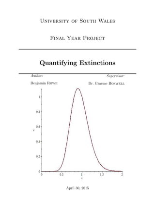
  • 53. v = c x2 exp( 2 [ln(x) − x + k]) (6.14) Referring back to the Logistic Equation, there are two stationary points where x = 0 is an unstable stationary point and x = 1 is a stable stationary point when the system is deterministic. The sample path Equation (6.14) of the logistic model is where there is an element of noise also present, hence the error term ( ). However, there is still an unknown variable k that has to be determined. Thinking about the logistic equation distribution graph: If the error term is small (i.e. Figure 6.1: A Graph to show the typical distribution of the deterministic Logistic Equa- tion. | | < 1) then the distribution of Equation (6.14) will look something similar to Figure 6.2. From this we can see that dv dx = 0 at x = 1. So it follows: dv dx = − 2c x3 exp 2 [ln(x) − (x − k)] + c x2 exp 2 [ln(x) − (x − k)] 2 1 x − 1 (6.15) Now substituting in what we know about vx then Equation (6.15) becomes: 0 = −2ce 2 (k−1) (6.16) 51
  • 54. From Equation either c = 0 which implies v = 0 or exp 2 (k − 1) = 0 for very small . Considering ex being approximated in Taylor form: ex = 1 + x + x2 2! + x3 3! ... (6.17) Then, e(2 (k−1)) = 1 + 2 (k − 1) + 2 2 (k − 1)2 2! + 2 3 (k − 1)3 3! + ... (6.18) When is small, (2 )n very quickly dominates and tends away from 0, unless k − 1 tends to 0 faster. From this if k = 1 then Equation (6.18) tends back towards 1 which is as close to 0 as possible. Substituting this value of k back into the sample path equation then: v = c x2 exp 2 [ln(x) − (x − 1)] (6.19) Figures 6.2, 6.3 and 6.4 where all solved with the fixed value of c = 1. They all carry 6.3 Numerical Analysis Figure 6.2: A Graph Plotting Equation (6.19) by using the Maple Code in Appendix C.1 where = 0.1, k = 1. a similar shape compared to the typical distribution graph of thee logistic equation, the 52
  • 55. Figure 6.3: A Graph Plotting Equation (6.19) by using the Maple Code in Appendix C.1 where = 0.01, k = 1. Figure 6.4: A Graph Plotting Equation (6.19) by using the Maple Code in Appendix C.1 where = 0.001, k = 1. main aim was to get the centre of the distribution around x = 1. It is clear to see that in the last three graphs that as epsilon is increased the wider the bell curve becomes, as well as when epsilon approaches 0 then the bell curve becomes very sharp very quickly. 53
  • 56. As the error term is increased it has been observed now that the distribution spreads a lot more evenly, compared to a sharp spike at x = 1, this is to be expected as now the element of noise can act as a measure of confidence for the collected data. The graph spreads out more as epsilon is increased because our error term is the measure of spread in the data. This spread in data means that confidence intervals can be introduced with a bit more work, choosing a suitable value of can give a suitable representation of the collected data and confidence limits can be associated with the estimates for times to extinction. Below in Figures 6.5 and 6.6 are still plotted with a fixed value of c = 1 but this time k is varied instead of . For good measure, it is possible to see that even with very small Figure 6.5: A Graph Plotting Equation (6.19) by using the Maple Code in Appendix C.1 where = 0.1, k = 0. changes in k, if it doesn’t equal 0 then the distribution graph for v very quickly tends to 0 if k < 1 and very rapidly shoots off to infinity if k > 1. Therefore keeping k = 1 makes logical sense to keep the distribution graph in good proportion. 54
  • 57. Figure 6.6: A Graph Plotting Equation (6.19) by using the Maple Code in Appendix C.1 where = 0.1, k = 2. 6.4 Discussion With some work starting from Equation (6.5) it is now possible to predict a more accurate population distribution that includes the error that would occur in real life situations. This method was able to be used with the Sample Path Equation as the rest of the work in this report were based on the same assumptions and equations. Looking at the graphs generated in Maple 18 with Appendix C.1 it is possible to see some of the effects of changing the variables in Equation (6.19). Changing the error term spreads the data out more and the bell curve in the middle therefore becomes wider as is increased. As → 0 then the line of the graphs slower approach to form the equation x = 1, and as → inf the line slowly straightens out as v approaches c x2 . These results make a lot of sense considering the Equation (6.19). With a little work k was found to be the most applicable to the situation when it equaled 1, this kept the population distribution graphs in a reasonable and realistic perspective. The fact that x = 1 is a stationary point of the Logistic Equation could also play a role 55
  • 58. and with some further work may be able to be shown. A similar result was found with fixing c to be 1 as well, but trying other values didn’t quite have the same dramatic effect on the graphs as the value of k. 56
  • 59. Chapter 7 Conclusions Having looked at discrete data and a continuum approach, whilst also considering de- terministic and stochastic approaches all the data fits together quite nicely. From the story of the heath hens in Chapter 1 it is possible to see that there were a lot of different occasions (here we called them catastrophes) where the population numbers were drasti- cally decreased. Having looked into further detail on the classification of a certain species survival chances the information was found that all animals are assessed on 5 criteria. The criteria the Red List use that was the main focus in this paper was the ’probability of extinction’. While the probability of extinction isn’t too difficult to calculate or gather data for its a very deterministic variable that needs some element of noise, or confidence limits, to justify the estimations made. The discrete data used in Chapter 2 was a very basic technique but set guidelines to how later on it was possible to do the same thing but with a continuum approach. In Chapter 2 however the probability distributions were created for unique values of K which proved to be consistent throughout the project and never had any visual differences, even when new variables were thrown into the equation. These distributions were based on work from Markov Chains. Even as the Markov Chains became increasingly messy and difficult to work with the results almost identical. Random simulation with NetLogo only backed this up further and that was also including an element of randomness. These 57
  • 60. results were very confidence boosting in that it all backs each other up and therefore has a high external validity. The equation in general form in Equation (4.21) was very promising to find, while it looks basic at the moment it only considers constant rates of catastrophes etc. If functions were put in there place here then the birth rates could be more realistic (e.g. young babies aren’t going to be giving birth but constant rate suggests so at the moment), functions to consider would be: the catastrophe rate; the birth rate; the death rate; and the probability of dying in a catastrophe may be a simple function or it may be completely determined by the type of catastrophe at hand. Another thing to look at would be different types of catastrophe, while famine may take longer to have effects its death rates during the catastrophe may be significantly larger than an epidemic for example. The next thing to consider is the expected times to extinction. In Chapter 2 these made no sense at all where the expected times to extinction oscillated around above and below 0, suggesting the population would become extinct and then suddenly be present again. Assuming a continuum approach however soon rectified this giving some very realistic looking graphs in Figures 3.1...3.3. These results showed characteristics of car- rying capacity and disperse populations when the population numbers were approaching 0. The general shape of these graphs retained a general shape throughout the paper but catastrophes had a very heavy effect on the vertical axis representing the times them- selves, where the values all dropped around 120 time units. At this stage the data was still assuming a deterministic approach and soon changed a little bit again when an error term was introduced. However the shape again held constant throughout. Looking at the birth and death rates these had the expected results as anyone could assume from the start, the higher the value of b(j) the longer the population would last, on average, this would be because the members of the population would be producing more offspring in their lifetimes and raising d(j) would have the opposite effect by giving the population less time to reproduce. The catastrophe rate had very small implications 58
  • 61. in the computer simulation compared to them predicted in previous chapters. There is still a lot of work to do with these rates as different species have different mortality rates at different ages (which is another factor to include with further work) such as in general the older the population becomes the more likely those members are to die. Also, as stated before very young offspring will have an extremely low reproductive rate and this will rise in times of maturity and drop once again in old age. Catastrophe rates will determine on the catastrophe at hand, for example if natural disasters are being considered then there could be a difference related to geographic location or if disease is at hand is one species more susceptible compared to others that it causes death in some but not others, also is the disease prominent in some areas compared to the other side of the planet for example. In the previous chapter, a lot of work based on D. Ludwig, went into observing the effects of on the sample path equation (Equation (6.19)) and the results were shown to be as expected. Increasing the value of made the distribution curves noticeably wider with every factor of 10 that was increased by; eventually if the error term is too large where it becomes insignificant then the curve starts to flatten out and the data would then be very difficult to analyse. Some further work may be done here to find a more reliable proof for setting the value of k to be 1, and also to see how these results compare to some of the deterministic approaches discussed in earlier chapters as → 0. It would also be interesting to see if the error term could be introduced somewhere to Equation (4.21) and compare to the work done in Chapter 6. With a bit more work, the next step here would be to look into moment generating formulae (similar to that of Mangel and Tier [7]) where the deterministic and stochastic equations could be interpreted with this approach and once again the results compared in more detail. The use of moment generating formulae could also bring about the in- troduction of standard deviation, which would lead to the confidence limits suggested in the introduction alongside the expected time to extinction as a replacement to the Red List criteria currently in place (probability of extinction). 59
  • 62. At the moment the work done here could make some estimates into the expected time to extinction up to about 50 years without any problems, and maybe even 100 years if the variables remained similar to the present time. This could be a very powerful tool and with a bit more work could possibly be a very efficient replacement of some of the Red List’s 5 criteria. Trying to use the material in this paper to generalise to populations that are vastly widespread across the planet (e.g. humans) would be very difficult as the work here is based on populations that are very specific in area. Like it was suggested earlier, generalising to wider areas could be introduced if a form of geographic location was somehow introduced depending on the area; for example humans can survive a lot easier in the United Kingdom compared to the middle of a desert.The introduction of so many factors however would complicate calculations very quickly and could result in a lot more data being needed to eventually take an average of several expected values overall. 60
  • 63. Bibliography [1] Image View of the Different State of the Red List. http : //commons.wikimedia.org/wiki/File : Status iucn3.1.svg (Accessed: 20th October 2014). [2] Donald Ludwig (1975) Persistence of Dynamical Systems Under Random Perturbations University of British Columbia [3] The Red List and how Species are Catagorised. http : //education.nationalgeographic.com/education/encyclopedia/endangered − species/?ar a = 1 (Accessed: 18th Jan 2015). [4] The Heath Hen on Martha’s Vineyard. http : //www.bagheera.com/inthewild/ext heathhen.htm (Accessed: 23rd October 2014). [5] Classification of Species Vulnerability. http : //education.nationalgeographic.com/education/encyclopedia/endangered − species/?ar a = 1 (Accessed: 19th Jan 2015). [6] B. J. Cairns and P.K. Pollett (2005) Approximating Persistence in a General Class of Population Processes University of Queensland 61
  • 64. [7] Marc Mangel and Charles Tier A Simple Direct Method for Finding Persistence Times of Populations and Applica- tion to Conservation Problems University of California 62
  • 65. Appendix A NetLogo Code A.1 Initial Simulation.nlogo ; variables globals [ current-turtles all-turtles-ever average-turtles ] ; the set up to setup clear-all set all-turtles-ever ( 0 ) setup-turtles update-turtle-globals reset-ticks end 63
  • 66. to setup-turtles create-turtles initial-density * cap ask turtles [ setxy random-xcor random-ycor ] end ; updating globals to update-turtle-globals set current-turtles ( count turtles ) set all-turtles-ever (all-turtles-ever + count turtles ) end ; main procedure to go if count turtles = 0 [ stop ] move-turtles birth death catastrophe update-turtle-globals tick export-files end 64
  • 67. to move-turtles ask turtles [ right random 360 forward 1 ] end to birth ask turtles [ if count turtles < cap [ if random-float 1.000 < probability-birth * count turtles [ hatch 1 ] ] ] end to death ask turtles [ if random-float 1.000 < probability-death * (count turtles)*(count turtles) [ die ] ] 65
  • 68. end to catastrophe ask turtles [ if random-float 1.000 < probability-catastrophe [ if random-float 1.000 < probability-death-catastrophe [ die ] ] ] end to export-data ;;set the directory where the file will be stored set-current-directory "C:UsersBenDocuments" ;; create the column headings once if ticks = 1 [create-files] export-files end to create-files ;; create the file and give the first row column headings file-open "Turtle-Tick Count.doc" file-print (list "total") file-close end to export-files ;; write the information to the file 66
  • 69. file-open "Turtle-Tick Count.doc" ask turtles [file-print (list count turtles)] file-close end 67
  • 70. Appendix B MatLab Code B.1 Dissertation.m %Defining ’Independent’ Variables K = 10; b = 0.1; d = 0.02; %Defining ’Base’ Matricies a = eye(K,K); c = zeros(K,K); B = ones(K,1); for j=1:K-1, a(j,j+1) = -b*j; a(j+1,j) = -d*j^2; end A = inv(a); 68
  • 71. C = zeros(K,1); P(1)= 0.0069595; for j = 1:K P(j+1) = (b*j*P(j))/(d*j^2); end for j = 1:K C(j,1) = P(j); end Z=0; for j = 1:K Z = Z+ P(j)*j; end p = 0.2; q = 0.001; for j=1:K c(j,j) = -(b*j + d*j*j + q + q*(1-p)^j); end c(K,K)=-d*K*K; for j=1:K-1 c(j,j+1) = b*j; c(j+1,j) = d*(j+1)*(j+1) + q*j*p*(1-p)^(j-1); end m_one = ones(K,1); for n=1:K for k=1:K if n - k >= 2 69
  • 72. r = nchoosek(n,k); c(n,k) = q*r*p^(n-k)*(1-p)^k; end end end A*m_one plot(A*m_one) B.2 Binomial.m % Using markov chains to obtain a distribution (with catastrophes) K = 10; P=zeros(K,1); P(K) = 0.000000000000013408/1.8844e-012/1.0682/1.0186/0.9312/2.0732; d = 0.02; b = 0.1; q = 1; p = 0.5; for a = K - 1: -1: 1 P_(a) = P(a + 1) * d * (a + 1)^2 + Binomial_Internal(a, K, P, p, q); P(a) = P_(a) / (b * a); end % A seperate function to work out the summation on the top of the % fraction used to calculate the probabilty distribution for % markov chains with catastrophes. 70
  • 73. function sumR = Binomial_Internal(a, K, P, p, q) %P = P(K) R = zeros(K,1); for i = 1: a % R(K, 1) = P * q * (nchoosek(K, i) * p^(K - i) * (1 - p)^(i)); for j = a+1:K R(i) = P(j) *q* (nchoosek(j, i) * p^(j-i) * (1 - p)^(i)); end end sumR = sum(R); B.3 Continuum Matrix.m % Defining indepedent variables K = 10; b = 0.1; d = 0.02; %%%%%%%%%%%%%%%%%%%%%%%%%%%%%%%%%%%%%%%%%%%%%%%%%%%%%%%%%%%%%%%%%%% % For a Continuum Approach C = zeros(K,1); P(1)= 0.0069595; p = 0.2; q = 0.001; 71
  • 74. for j=1:K c(j,j) = -(b*j + d*j*j + q + q*(1-p)^j); end c(K,K)=-d*K*K; for j=1:K-1 c(j,j+1) = b*j; c(j+1,j) = d*(j+1)*(j+1) + q*j*p*(1-p)^(j-1); for i=1:j-2 c(j,i) = i*nchoosek(j,i)*p^(j-i)*(1*p)^i; end end minusone = (-1)*ones(K,1); for n=1:K for k=1:K if n - k >= 2 r = nchoosek(n,k); c(n,k) = q*r*p^(n-k)*(1-p)^k; end end end % %%%%%%%%%%%%%%%%%%%%%%%%%%%%%%%%%%%%%%%%%%%%%%%%%%%%%%%%%%%%%%%%%%% plot(cminusone) 72
  • 75. Appendix C Maple Code C.1 V Graphs.mw c := 1: epsilon := 0.1: k := 1: v := (c/(x^2))*exp((2/epsilon)*(ln(x)-(x-k))): plot(v,x=0..2); 73