Ccie And Ccde Written Exam Evolving Technologies Version 11 Study Guide Nicholas J Russo
Ccie And Ccde Written Exam Evolving Technologies Version 11 Study Guide Nicholas J Russo
Ccie And Ccde Written Exam Evolving Technologies Version 11 Study Guide Nicholas J Russo


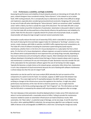

![As Voyager 1 approached Jupiter, the resolution of the images steadily
improved. In October 1978, at a distance of about 125 million kilometers,
the image was less clear than would be obtained with an Earth-based
telescope. [P-20790]](https://image.slidesharecdn.com/26819583-250512185031-6cb3f2ed/85/Ccie-And-Ccde-Written-Exam-Evolving-Technologies-Version-11-Study-Guide-Nicholas-J-Russo-29-320.jpg)
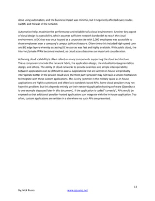
![By December 10, the spacecraft had moved to a distance of 85 million
kilometers, and the resolution was about 2000 kilometers, comparable to
the best telescopic images. [P-20829C]](https://image.slidesharecdn.com/26819583-250512185031-6cb3f2ed/85/Ccie-And-Ccde-Written-Exam-Evolving-Technologies-Version-11-Study-Guide-Nicholas-J-Russo-30-320.jpg)
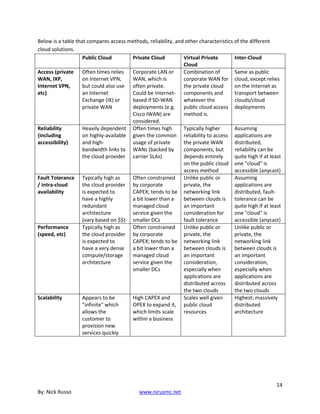
![On January 9, 1979 (c), at a distance of 54 million kilometers, the image
surpassed all ground-based views and approached the resolution of the
Pioneer 10 and 11 photos. [P-20926C]](https://image.slidesharecdn.com/26819583-250512185031-6cb3f2ed/85/Ccie-And-Ccde-Written-Exam-Evolving-Technologies-Version-11-Study-Guide-Nicholas-J-Russo-31-320.jpg)
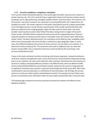
![58
In this, taken January 24 at a distance of 40 million kilometers, the
resolution exceeded 1000 kilometers. [P-20945C]
The Observatory Phase](https://image.slidesharecdn.com/26819583-250512185031-6cb3f2ed/85/Ccie-And-Ccde-Written-Exam-Evolving-Technologies-Version-11-Study-Guide-Nicholas-J-Russo-32-320.jpg)
![59
The Galilean satellites of Jupiter first began to show as tiny worlds, not
mere points of light, as the Voyager 1 observatory phase began. In this
view taken January 17, 1979, at a range of 47 million kilometers, the
differing sizes and surface reflectivities (albedos) of Ganymede (right
center) and Europa (top right) are clearly visible. The view of Jupiter is
unusual in that the Great Red Spot is not easily visible, but can just be
seen at the right edge of the planet. Most pictures selected for
publication include the photogenic Red Spot. [P-20938C]
Far Encounter Phase
By early February Jupiter loomed too large in the narrow-angle
camera to be photographed in one piece; 2 × 2 three-color (violet,
orange, green) sets of pictures were taken for the next two weeks;
by February 21, Jupiter had grown too large even for that, and 3 × 3
sets were scheduled to begin. When these sets of pictures are pasted
together to form a single picture, the result is called a mosaic.](https://image.slidesharecdn.com/26819583-250512185031-6cb3f2ed/85/Ccie-And-Ccde-Written-Exam-Evolving-Technologies-Version-11-Study-Guide-Nicholas-J-Russo-34-320.jpg)
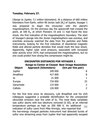
![By February 1, 1979, Voyager 1 was only 30 million kilometers from
Jupiter, and the resolution of the imaging system corresponded to about
600 kilometers at the cloud tops of the giant planet. At this time, a great
deal of unexpected complexity became apparent around the Red Spot,
and movie sequences clearly showed the cloud motions, including the
apparent six-day rotation of the Red Spot. [P-20993C]](https://image.slidesharecdn.com/26819583-250512185031-6cb3f2ed/85/Ccie-And-Ccde-Written-Exam-Evolving-Technologies-Version-11-Study-Guide-Nicholas-J-Russo-35-320.jpg)
![60
One of the most spectacular planetary photographs ever taken was
obtained on February 13 as Voyager 1 continued its approach to Jupiter.
By this time, at a range of 20 million kilometers, Jupiter loomed too large
to fit within a single narrow-angle imaging frame. Passing in front of the
planet are the inner two Galilean satellites. Io, on the left, already shows
brightly colored patterns on its surface, while Europa, on the right, is a
bland ice-covered world. The scale of all of these objects is huge by
terrestrial standards; Io and Europa are each the size of our Moon, and
the Red Spot is larger than the Earth. [P-21082C]
While the imaging experiments were in the limelight, the other
scientific instruments had also begun to concentrate on the Jovian
system. The ultraviolet spectrometer had been scanning the region
eight times a day; the infrared spectrometer (IRIS) spent 1½ hours a
day analyzing infrared emissions from various longitudes in Jupiter’s
atmosphere; the planetary radio astronomy and plasma wave](https://image.slidesharecdn.com/26819583-250512185031-6cb3f2ed/85/Ccie-And-Ccde-Written-Exam-Evolving-Technologies-Version-11-Study-Guide-Nicholas-J-Russo-36-320.jpg)
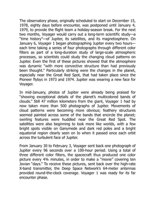
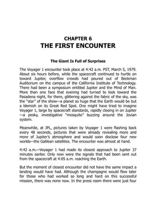
![The Voyager Project was operated from the Jet Propulsion Laboratory
managed for NASA by the California Institute of Technology. Located in
the hills above Pasadena, California, JPL is the main center for U.S.
exploration of the solar system. [JB17249BC]](https://image.slidesharecdn.com/26819583-250512185031-6cb3f2ed/85/Ccie-And-Ccde-Written-Exam-Evolving-Technologies-Version-11-Study-Guide-Nicholas-J-Russo-38-320.jpg)
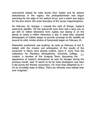
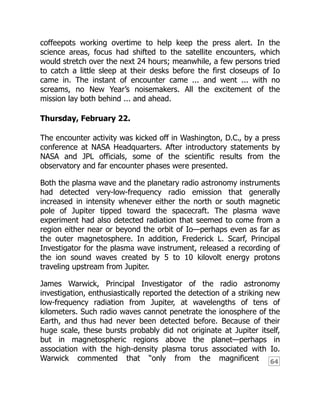
![62
The colors used to print the three separate frames can be seen clearly in
the nonoverlapping areas. For other pictures in this book, the
nonoverlapping partial frames are omitted. [P-21192]
The pictures from Voyager are “clearly spectacular,” said Lonne Lane,
Assistant Project Scientist for Jupiter. “We’re getting even better
results than we had anticipated. We have seen new phenomena in
both optical and radio emissions. We have definitely seen things that
are different—in at least in one case, unanticipated—and are begging
for answers we haven’t got.” There was already, still almost a month
from encounter, a strong feeling of accomplishment among the
scientists and engineers; they had done a difficult task and it has
been successful.
By the last week of February 1979, the attention of thousands of
individuals was focused on the activities at JPL. Scientists had arrived
from universities and laboratories around the country and from
abroad, many bringing graduate students or faculty colleagues to
assist them. Engineers and technicians from JPL contractors joined
NASA officials as the Pasadena motels filled up. Special badges were
issued and reserved parking areas set aside for the Voyager influx.
Twenty-four hours a day, lights burned in the flight control rooms, the
science offices, the computer areas, and the photo processing labs.
In order to protect those with critical tasks to perform from the
friendly distraction of the new arrivals, special computer-controlled
locks were placed on doors, and security officers began to patrol the
halls. By the end of the month the press had begun to arrive. Amid
accelerating excitement, the Voyager 1 encounter was about to
begin.](https://image.slidesharecdn.com/26819583-250512185031-6cb3f2ed/85/Ccie-And-Ccde-Written-Exam-Evolving-Technologies-Version-11-Study-Guide-Nicholas-J-Russo-40-320.jpg)
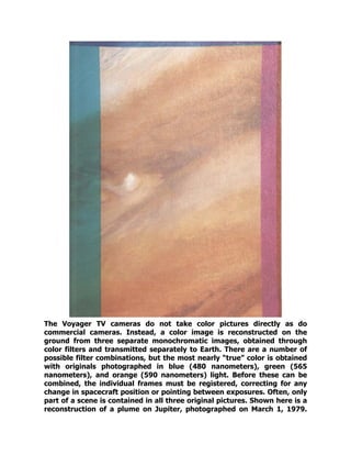
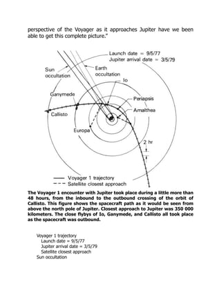
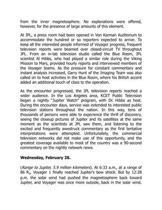
![63
where one can see to greater depths in the atmosphere. This photo was
taken March 1 from a distance of 4 million kilometers. [P-21183C]](https://image.slidesharecdn.com/26819583-250512185031-6cb3f2ed/85/Ccie-And-Ccde-Written-Exam-Evolving-Technologies-Version-11-Study-Guide-Nicholas-J-Russo-42-320.jpg)
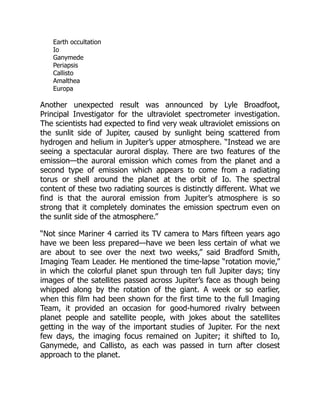
![Not until March 2, at a distance of less than 45 RJ, would the
spacecraft enter the magnetosphere for the final time.
At 11 a.m. the first daily briefing to the press was given. “After nearly
two months of atmospheric imaging and perhaps a week or two of
satellite viewing, [we’re] happily bewildered,” said Brad Smith. The
Jovian atmosphere is “where our greatest state of confusion seems to
exist right at the moment, although over the next several days we
may find that some of our smirking geology friends will find
themselves in a similar state. I think, for the most part, we have to
say that the existing atmospheric circulation models have all been
shot to hell by Voyager. Although these models can still explain some
of the coarse zonal flow patterns, they fail entirely in explaining the
detailed behavior that Voyager is now revealing.” It was thought,
from Pioneer results, that Jupiter’s atmosphere showed primarily
horizontal or zonal flow near the equatorial region, but that the zonal
flow pattern broke down at high latitudes. But Voyager found that
“zonal flow exists poleward as far as we can see.”
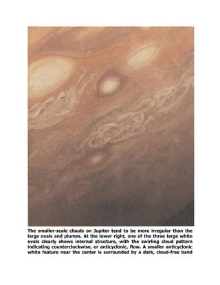
Smith also showed a time-lapse movie of Jupiter assembled from
images obtained during the month of January. Once each rotation,
approximately every ten hours, a color picture had been taken.
Viewed consecutively, these frames displayed the complex cloud
motions on a single hemisphere of Jupiter, as they would be seen
from a fixed point above the equator of the planet. The film revealed
that clouds move around the Great Red Spot in a period of about six
days, at speeds of perhaps 100 meters per second. The Great Red
Spot, as well as many of the smaller spots that dot the planet,
appeared to be rotating anticyclonically. Anticyclonic motion is
characteristic of high-pressure regions, unlike terrestrial storms.
Smith noted that “Jupiter is far more complex in its atmospheric
motions than we had ever imagined. We are seeing a much more
complicated flow of cyclonic and anticyclonic vorticity, circulation. We
see currents which flow along and seem to interact with an obstacle
and turn around and flow back.” There is a Jovian jet stream that is
“moving along at well over 100 meters per second. Several of these](https://image.slidesharecdn.com/26819583-250512185031-6cb3f2ed/85/Ccie-And-Ccde-Written-Exam-Evolving-Technologies-Version-11-Study-Guide-Nicholas-J-Russo-49-320.jpg)