Download to read offline

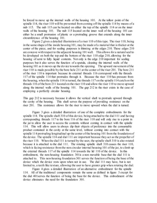
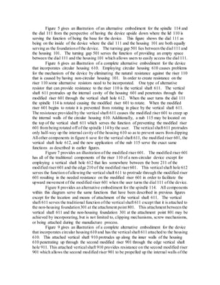


The document describes a provisional patent application for a device designed to facilitate the extraction of semi-liquid and liquid contents from various containers, particularly for dipping snacks. This invention addresses shortcomings of traditional containers by using a riser mechanism that elevates the contents without the need for users to tilt the container or insert utensils, thus improving convenience and usability. The document contains detailed descriptions and illustrations of multiple embodiments and components of the invention, focusing on their functions and design features.


![[NALL OCR] HALL, Basil (1824). Extracts from a journal written on the coasts ...](https://cdn.slidesharecdn.com/ss_thumbnails/nallocrhallbasil1824-260202221936-b93ec330-thumbnail.jpg?width=640&height=640&fit=bounds)


