Projection of planes 033
•Download as PPTX, PDF•
1 like•2,358 views

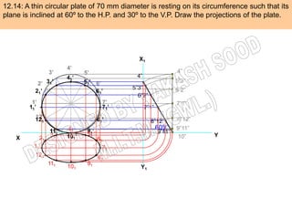
A thin circular plate with a diameter of 70 mm is resting on its circumference. The plate is inclined at 60° to the horizontal plane and 30° to the vertical plane. Draw the front and side views of the inclined circular plate.
Report
Share
Report
Share
Recommended
Projection of planes 038
The document provides instructions for drawing two projections of a circle resting on a horizontal plane (HP) that is inclined at 45 degrees to the HP.
In the first problem (12.8a), the top view shows the diameter AB making a 30 degree angle with the vertical plane (VP). In the second problem (12.8b), the true length (TL) of the diameter AB makes a 30 degree angle with the VP.
The only difference between the two problems is in the third step, where problem 12.8a shows the inclination of the true view (TV) of AB, while 12.8b shows the angle of the true length (TL) of AB itself.
EG UNIT-II PROJECTION OF PLANES.ppt
This document discusses the projection of planes in engineering graphics. It defines key terms like trace of a plane and horizontal and vertical traces. It describes the different orientations a plane can have in space, such as parallel or perpendicular to the vertical or horizontal planes. It provides examples of how to represent different views of objects in planes using notations. Finally, it includes several example problems demonstrating how to draw the projections of planes in different orientations.
Projection of planes 032
The document provides instructions to draw a rhombus with diagonals of 125 mm and 50 mm, where the smaller 50 mm diagonal is parallel to both principal planes and the larger 125 mm diagonal is inclined at 30 degrees to the horizontal plane. To do this, the steps are to keep one side parallel to the horizontal plane and perpendicular to the vertical plane, and to incline the opposite side 30 degrees to the horizontal plane, making the other two sides parallel to the coordinate planes.
Projection of planes 025
A regular hexagon with 25mm sides has one side lying in the horizontal plane and inclined at 60 degrees to the vertical plane. The surface of the hexagon is inclined at 45 degrees to the horizontal plane. To show the true shape, the vertical plane view will show the hexagon with one side vertical and the other sides projected accordingly. The initial position should assume the plane is parallel to the horizontal plane.
Eg projection of plane
Here are the steps to solve this problem:
1. Draw the top view of the rhombus with the longer diagonal horizontal at 100 mm.
2. This top view represents the true shape and size of the square in its top view.
3. Since the top view shows the true shape, the surface of the square must be parallel to the VP.
4. Draw the front view of the square below the top view, with the sides parallel to the XY line and of length 100 mm each.
5. The front view will also show the true shape and size of the square since its surface is parallel to the VP.
Therefore, the front view of the square is another square of side 100 mm, drawn
Projections of Planes
The document discusses various methods for projecting planes in engineering graphics. It provides step-by-step procedures for drawing projections of planes in different orientations and positions in space. Several example problems are presented with diagrams showing how to draw the front, top, and side views of planes such as rectangles, triangles, and other shapes in various orientations. Methods are described for determining the true shape, size, and angles between planes based on their given projections.
Projection of planes 030
The document provides instructions for drawing the top view of a circular plate given its appearance as an ellipse in the front view. Specifically, it states that:
1) A circular plate appearing as an ellipse in the front view has a major axis of 50 mm and minor axis of 30 mm.
2) To draw the top view, the major axis of the ellipse in the front view should be drawn horizontally.
Projection of planes 009
The document describes how to solve two problems involving drawing the projections of a rhombus.
1. Problem 6 gives the inclination of one diagonal to the horizontal plane (HP) and the true view (TV) of the same diagonal. The TV is drawn first showing the rhombus below the X-Y line with the longer diagonal parallel to it.
2. Problem 7 gives the inclinations of the longer diagonal to both HP and vertical plane (VP). The true length (TL) of the diagonal is drawn using its inclination to HP, and the locus is used to mark the TV.
3. The key difference is that in Problem 6 the TV is given directly, while in Problem 7 the
Projection of lines(new)
an useful presentation for all 1st year engineering students who are afraid of the subject : ENGINEERING GRAPHICS
learn, enjoy~
Projection of planes 020
An isosceles triangle plate with a 50mm base and 70mm altitude is placed such that its front view appears as an equilateral triangle with 50mm sides and one side inclined at 45 degrees. To draw the top view: first draw the front view as an equilateral triangle; then draw one side of the front view inclined at 45 degrees to represent how that side appears from above; this gives the shape of the top view.
Unit 3 projection of planes
The document discusses the procedure for drawing projections of plane figures. It explains that problems will provide the description and position of the plane figure relative to the horizontal and vertical planes. The position is described by the inclination of the surface to one plane and the inclination of an edge to the other plane. It demonstrates solving problems in three steps: 1) Draw initial projections assuming positions, 2) Draw projections after changing surface inclination, 3) Draw final projections after changing edge inclination. Several example problems are provided and discussed step-by-step.
Projection of planes 026
A circle with a diameter of 5 cm is positioned with its plane vertical and inclined at 30 degrees to the vertical plane. The circle's center is located 3 cm above the horizontal plane and 2 cm in front of the vertical plane. The summary shows the top-down and front projections of the circle along with its traces on the horizontal and vertical planes.
Projection of planes 022
A regular hexagon with a 40mm side has one corner located in the horizontal plane (HP). The surface containing this hexagon is inclined at 45 degrees to the HP and is perpendicular to the vertical plane (VP). When viewed from above, the diagonal passing through the corner in the HP makes an angle of 60 degrees with the VP. Draw the front, top, and side views of this hexagon and diagonal.
Projection of planes 021
The document provides instructions for drawing the projections of a semicircular plate that is inclined in multiple ways. The plate has a diameter of 80mm and its straight edge is in the vertical plane (VP) and inclined at 45 degrees to the horizontal plane (HP). The surface of the plate makes an angle of 30 degrees to the VP. The projections should be drawn with the VP parallel to the drawing plane and one side of the resulting hexagon vertical.
Projection of planes
The document provides information on the projection of plane figures:
1) It explains the basics of plane projection problems, including what is typically given (projections of the plane) and asked for (its position relative to reference planes).
2) Plane figures can have their surface parallel or inclined to the horizontal or vertical planes, and edges parallel or inclined to the other reference plane. The document demonstrates solving problems through 3 steps of initial positioning, surface inclination, and edge inclination.
3) Several example problems are worked through step-by-step to show determining the front, top, and side views of planes in different orientations, such as a pentagon inclined to the horizontal plane and a side to the vertical plane
Projection of lines
The document discusses the orthographic projections of straight lines. It defines five basic cases of lines: vertical, parallel to both planes, inclined to one plane and parallel to the other, inclined to both planes. It provides pictorial representations of each case and notes about front and top views. The document then presents several example problems demonstrating how to draw the projections of a line given information like its true length, angles of inclination, and positions of its ends. Diagrams illustrate the key steps and parameters involved in the problems.
Projection of Planes
For case (a): The plane makes an angle of 30° with the H.P.
For case (b): The plane makes an angle of 60° with the H.P.
In both cases, the hexagonal plate of 40mm size is shown with one corner on the H.P. and the diagonal through that corner inclined at 30° to the H.P. and V.P.
Projection of Lines
The problem provides the top view, front view and position of one end of a line AB. The top view measures 65mm, the front view measures 50mm, and end A is in the horizontal plane and 12mm in front of the vertical plane. To solve the problem:
1) Draw the top view parallel to the XY line since in that case the front view will show the true length.
2) Extend the top view to determine the true length of 75mm.
3) Use trapezoidal method to determine the inclinations of the line with the principal planes as 30 degrees with the horizontal plane and 48 degrees with the vertical plane.
Projection of pentagon plane
A 30 mm regular pentagon rests on horizontal plane (HP) with one side on HP and the surface inclined at 45 degrees to HP. The problem is to draw the projections when the side in HP makes a 30 degree angle to the vertical plane (VP).
The front and top views of the pentagon are drawn showing the projections of points with letters. Projectors are drawn and the top view shows the side in HP at a 30 degree angle to VP, as required.
Projection of planes 004
1. The rectangle is resting on its horizontal plane (HP) on one small side that makes a 300 inclination to the vertical plane (VP).
2. The surface of the plane makes a 450 inclination to the HP.
3. In the front view, the true shape of the rectangle will be shown since the surface is inclined to the HP. The side making a 300 inclination to the VP will be vertical in the front view.
Projection of planes
1. The document discusses projections of plane figures, specifically front, top, and side views.
2. It provides examples of a rectangle with its surface and edges inclined to reference planes.
3. The reader is instructed to apply the steps of projecting inclined planes and edges to solve 11 problems drawing various shapes.
Projection of planes 027
A square with a 50 mm side has its corner A in the horizontal plane. Its diagonal AC is inclined at 30 degrees to the horizontal plane. The diagonal BD is inclined at 45 degrees to the vertical plane and parallel to the horizontal plane. The projections of the square are drawn with diagonal AC parallel to the horizontal plane and inclined at 30 degrees in the front view. Diagonal BD is inclined at 45 degrees to the vertical plane in both the front and top views.
Projection of solids - ENGINEERING DRAWING/GRAPHICS
Projection of solids
HIS SLIDE CONTAINS WHOLE SYLLABUS OF ENGINEERING DRAWING/GRAPHICS. IT IS THE MOST SIMPLE AND INTERACTIVE WAY TO LEARN ENGINEERING DRAWING.SYLLABUS IS RELATED TO rajiv gandhi proudyogiki vishwavidyalaya / rajiv gandhi TECHNICAL UNIVERSITY ,BHOPAL.
Projection of planes 029
A thin rectangular plate with dimensions 60 mm x 30 mm has its shorter side along the vertical plane and inclined at 30 degrees to the horizontal plane. Its top view can be projected by first drawing its front view as a 30 mm square. The front view is then inclined at 30 degrees to the horizontal plane to project the top view.
Projection of planes
an useful presentation for all those 1st year engineering students who are afraid of ENGINEERING GRAPHICS..
learn, enjoy~
Projection of planes
1. A plane is a two-dimensional geometrical entity with length and width but no thickness. For practical purposes, a flat face of an object may be treated as a plane.
2. When projecting a plane, its shape, inclination to reference planes, and the inclination of edges are given. Planes can be parallel or inclined to one or both reference planes.
3. This document provides examples of projecting rectangular and pentagonal planes in different positions relative to the reference planes. The examples demonstrate determining the true shape view and projecting points for planes oriented parallel or inclined to the horizontal and vertical planes.
Projection of planes
This document provides instructions for projecting plane figures given their position relative to the horizontal and vertical planes. It begins by describing what information is typically provided in projection problems involving planes: a description of the plane figure and its position relative to the HP and VP defined by an inclination. Common steps for solving these problems are outlined, including making initial assumptions, projecting the inclined surface, and projecting the inclined edge. An example problem of projecting a rectangle with a surface inclined to the HP and edge inclined to the VP is shown. The key steps of the procedure are to first draw projections assuming the initial position, then incorporate the surface inclination, and finally the edge inclination.
Development of surfaces of solids
an important slideshow for all engineers, who are afraid of the subject : ENGINEERING GRAPHICS..
learn, enjoy~
Projection of planes 041
The document describes how to incline a plane and its edge from an initial parallel position. It assumes the plane is initially parallel to a principal plane and the edge is perpendicular to that plane. The steps are to first incline the plane and then incline the edge.
Projection of planes 023
A circular plate with a diameter of 60mm is inclined at 60 degrees to the horizontal plane. The top view is a circle, the front view shows the circle intersected by the inclined surface, and the side view shows the circular edge of the plate.
More Related Content
What's hot
Projection of lines(new)
an useful presentation for all 1st year engineering students who are afraid of the subject : ENGINEERING GRAPHICS
learn, enjoy~
Projection of planes 020
An isosceles triangle plate with a 50mm base and 70mm altitude is placed such that its front view appears as an equilateral triangle with 50mm sides and one side inclined at 45 degrees. To draw the top view: first draw the front view as an equilateral triangle; then draw one side of the front view inclined at 45 degrees to represent how that side appears from above; this gives the shape of the top view.
Unit 3 projection of planes
The document discusses the procedure for drawing projections of plane figures. It explains that problems will provide the description and position of the plane figure relative to the horizontal and vertical planes. The position is described by the inclination of the surface to one plane and the inclination of an edge to the other plane. It demonstrates solving problems in three steps: 1) Draw initial projections assuming positions, 2) Draw projections after changing surface inclination, 3) Draw final projections after changing edge inclination. Several example problems are provided and discussed step-by-step.
Projection of planes 026
A circle with a diameter of 5 cm is positioned with its plane vertical and inclined at 30 degrees to the vertical plane. The circle's center is located 3 cm above the horizontal plane and 2 cm in front of the vertical plane. The summary shows the top-down and front projections of the circle along with its traces on the horizontal and vertical planes.
Projection of planes 022
A regular hexagon with a 40mm side has one corner located in the horizontal plane (HP). The surface containing this hexagon is inclined at 45 degrees to the HP and is perpendicular to the vertical plane (VP). When viewed from above, the diagonal passing through the corner in the HP makes an angle of 60 degrees with the VP. Draw the front, top, and side views of this hexagon and diagonal.
Projection of planes 021
The document provides instructions for drawing the projections of a semicircular plate that is inclined in multiple ways. The plate has a diameter of 80mm and its straight edge is in the vertical plane (VP) and inclined at 45 degrees to the horizontal plane (HP). The surface of the plate makes an angle of 30 degrees to the VP. The projections should be drawn with the VP parallel to the drawing plane and one side of the resulting hexagon vertical.
Projection of planes
The document provides information on the projection of plane figures:
1) It explains the basics of plane projection problems, including what is typically given (projections of the plane) and asked for (its position relative to reference planes).
2) Plane figures can have their surface parallel or inclined to the horizontal or vertical planes, and edges parallel or inclined to the other reference plane. The document demonstrates solving problems through 3 steps of initial positioning, surface inclination, and edge inclination.
3) Several example problems are worked through step-by-step to show determining the front, top, and side views of planes in different orientations, such as a pentagon inclined to the horizontal plane and a side to the vertical plane
Projection of lines
The document discusses the orthographic projections of straight lines. It defines five basic cases of lines: vertical, parallel to both planes, inclined to one plane and parallel to the other, inclined to both planes. It provides pictorial representations of each case and notes about front and top views. The document then presents several example problems demonstrating how to draw the projections of a line given information like its true length, angles of inclination, and positions of its ends. Diagrams illustrate the key steps and parameters involved in the problems.
Projection of Planes
For case (a): The plane makes an angle of 30° with the H.P.
For case (b): The plane makes an angle of 60° with the H.P.
In both cases, the hexagonal plate of 40mm size is shown with one corner on the H.P. and the diagonal through that corner inclined at 30° to the H.P. and V.P.
Projection of Lines
The problem provides the top view, front view and position of one end of a line AB. The top view measures 65mm, the front view measures 50mm, and end A is in the horizontal plane and 12mm in front of the vertical plane. To solve the problem:
1) Draw the top view parallel to the XY line since in that case the front view will show the true length.
2) Extend the top view to determine the true length of 75mm.
3) Use trapezoidal method to determine the inclinations of the line with the principal planes as 30 degrees with the horizontal plane and 48 degrees with the vertical plane.
Projection of pentagon plane
A 30 mm regular pentagon rests on horizontal plane (HP) with one side on HP and the surface inclined at 45 degrees to HP. The problem is to draw the projections when the side in HP makes a 30 degree angle to the vertical plane (VP).
The front and top views of the pentagon are drawn showing the projections of points with letters. Projectors are drawn and the top view shows the side in HP at a 30 degree angle to VP, as required.
Projection of planes 004
1. The rectangle is resting on its horizontal plane (HP) on one small side that makes a 300 inclination to the vertical plane (VP).
2. The surface of the plane makes a 450 inclination to the HP.
3. In the front view, the true shape of the rectangle will be shown since the surface is inclined to the HP. The side making a 300 inclination to the VP will be vertical in the front view.
Projection of planes
1. The document discusses projections of plane figures, specifically front, top, and side views.
2. It provides examples of a rectangle with its surface and edges inclined to reference planes.
3. The reader is instructed to apply the steps of projecting inclined planes and edges to solve 11 problems drawing various shapes.
Projection of planes 027
A square with a 50 mm side has its corner A in the horizontal plane. Its diagonal AC is inclined at 30 degrees to the horizontal plane. The diagonal BD is inclined at 45 degrees to the vertical plane and parallel to the horizontal plane. The projections of the square are drawn with diagonal AC parallel to the horizontal plane and inclined at 30 degrees in the front view. Diagonal BD is inclined at 45 degrees to the vertical plane in both the front and top views.
Projection of solids - ENGINEERING DRAWING/GRAPHICS
Projection of solids
HIS SLIDE CONTAINS WHOLE SYLLABUS OF ENGINEERING DRAWING/GRAPHICS. IT IS THE MOST SIMPLE AND INTERACTIVE WAY TO LEARN ENGINEERING DRAWING.SYLLABUS IS RELATED TO rajiv gandhi proudyogiki vishwavidyalaya / rajiv gandhi TECHNICAL UNIVERSITY ,BHOPAL.
Projection of planes 029
A thin rectangular plate with dimensions 60 mm x 30 mm has its shorter side along the vertical plane and inclined at 30 degrees to the horizontal plane. Its top view can be projected by first drawing its front view as a 30 mm square. The front view is then inclined at 30 degrees to the horizontal plane to project the top view.
Projection of planes
an useful presentation for all those 1st year engineering students who are afraid of ENGINEERING GRAPHICS..
learn, enjoy~
Projection of planes
1. A plane is a two-dimensional geometrical entity with length and width but no thickness. For practical purposes, a flat face of an object may be treated as a plane.
2. When projecting a plane, its shape, inclination to reference planes, and the inclination of edges are given. Planes can be parallel or inclined to one or both reference planes.
3. This document provides examples of projecting rectangular and pentagonal planes in different positions relative to the reference planes. The examples demonstrate determining the true shape view and projecting points for planes oriented parallel or inclined to the horizontal and vertical planes.
Projection of planes
This document provides instructions for projecting plane figures given their position relative to the horizontal and vertical planes. It begins by describing what information is typically provided in projection problems involving planes: a description of the plane figure and its position relative to the HP and VP defined by an inclination. Common steps for solving these problems are outlined, including making initial assumptions, projecting the inclined surface, and projecting the inclined edge. An example problem of projecting a rectangle with a surface inclined to the HP and edge inclined to the VP is shown. The key steps of the procedure are to first draw projections assuming the initial position, then incorporate the surface inclination, and finally the edge inclination.
Development of surfaces of solids
an important slideshow for all engineers, who are afraid of the subject : ENGINEERING GRAPHICS..
learn, enjoy~
What's hot (20)
Projection of solids - ENGINEERING DRAWING/GRAPHICS
Projection of solids - ENGINEERING DRAWING/GRAPHICS
More from Akash Sood
Projection of planes 041
The document describes how to incline a plane and its edge from an initial parallel position. It assumes the plane is initially parallel to a principal plane and the edge is perpendicular to that plane. The steps are to first incline the plane and then incline the edge.
Projection of planes 023
A circular plate with a diameter of 60mm is inclined at 60 degrees to the horizontal plane. The top view is a circle, the front view shows the circle intersected by the inclined surface, and the side view shows the circular edge of the plate.
Projection of planes 010
This document provides instructions for drawing the projections of a circle resting on its diameter, where:
1. The diameter AC is inclined 300 to the horizontal plane.
2. The true view of the circle makes a 450 angle to the vertical plane.
3. To draw the projections, begin with the top view where the diameter will appear as a rhombus, taking the longer diagonal parallel to the XY line. Then complete the front view based on the angles given.
Projection of planes 008
A 30 mm regular pentagon rests on a horizontal plane (HP) with one side on the HP and the opposite vertex 30 mm above the HP. To draw the projections:
1) Draw the top view (TV) with any side of the pentagon vertical.
2) Draw the front view (FV) below the TV, making one side of the pentagon 30 mm above the HP to represent the given positioning.
3) The side inclination is directly given as 300, while the surface inclination is indirectly given by the positioning description.
Projection of planes 006
1. The surface of a 300-600 mm long set square is inclined 450 to the vertical plane (VP).
2. One end is 10 mm above the horizontal plane (HP) and the other end is 35 mm above the HP.
3. The longest side of the set square will be drawn vertically in the front view, with one end at 10 mm and the other at 35 mm above the HP, to show the true shape inclined 450 to the VP.
Projection of planes 003
The document outlines a 3-step procedure for solving problems involving inclined planes and surfaces:
1) Draw the front and top views assuming the surface is parallel to the reference plane.
2) Draw second front and top views considering the surface's true inclination.
3) Draw final front and top views accounting for any side/edge inclinations.
Initial positions should assume surfaces parallel to either the horizontal or vertical plane.
References to previous illustrations provide examples of applying each step.
Projection of planes 002
The document describes three orientations of a rectangle:
1) With a surface parallel to the horizontal plane, shown in a pictorial presentation and orthographic front view with the true shape.
2) With a surface inclined to the horizontal plane, shown in a pictorial presentation and orthographic front view inclined to the XY plane with a reduced shape.
3) With one small side inclined to the vertical plane, shown in a pictorial presentation and orthographic front view with the previous shape apparent.
Projection of planes 001
The document discusses projecting plane figures and describes what is typically asked and given in projection problems. Problems usually ask for the front, top, and side views (F.V, T.V., and S.V.) of a plane figure. The problems provide a description of the plane figure as well as its position relative to the horizontal and vertical planes through either the surface's inclination to a reference plane or an edge's inclination to the other reference plane.
Projection of planes 007
1) A regular pentagon with 30 mm sides rests on the horizontal plane (HP) with one side making a 45 degree angle to the HP.
2) The problem asks to draw the projections of the pentagon when that side makes a 30 degree angle to the vertical plane (VP).
3) Since the side and surface inclinations are given, the top view (TV) should be drawn first with one side vertical below the XY line.
Projection of planes 039
This document outlines 6 problems related to projecting planes in 3D space. Problem 1 deals with a plane where the surface is inclined to the horizontal plane and the edge is inclined to the vertical plane. Problems 2-4 vary the inclinations of the surface and edge to the horizontal and vertical planes. Problem 5 involves a surface perpendicular to the profile plane and inclined to both the horizontal and vertical planes. Problem 6 addresses the edge of a plane being inclined to both the horizontal and vertical planes.
Projection of planes 037
The document provides instructions to draw a rhombus with diagonals measuring 100mm and 60mm, with the longer diagonal horizontal. It states that the rhombus is the top view of a square with 100mm diagonals. It then instructs the reader to draw the front view of the square.
Projection of planes 035
An equilateral triangle with 75 mm sides has a circle inscribed within it. Projections of the figure are drawn with the plane vertical and inclined at 30 degrees, with one side of the triangle at 45 degrees to the horizontal plane.
Projection of planes 034
A regular hexagonal plate with a 40 mm diameter hole at its center is drawn. The projections of the plate are shown when the surface is vertical and inclined at 30 degrees to the view plane. Key views include a top view, front view, and inclined view showing the hexagonal shape and centered circular hole from different angles.
Projection of planes 024
A regular pentagon with sides of 25mm has one side lying on the ground plane. The pentagon's plane is inclined at 45 degrees to the horizontal plane and perpendicular to the vertical plane. The front and top views of the pentagon are drawn showing the traces where the pentagon's plane intersects the horizontal and vertical planes.
Projection of planes 017
This document provides instructions for determining the true shape of a triangular plate when given its front and top views. It explains that since no line is parallel to the XY axes in either view, one line should be drawn parallel in one view to serve as the true length. Here, the a'1 line is drawn parallel in the front view, making its corresponding top view line a-1 the true length. Then the same steps as the previous problem can be followed to determine the true shape by using distances from the front and top views.
Akash rivet joint
A rivet is a round rod used to join metal parts. It has a head on one end and a shank on the other. Common metals for rivets include steel, iron, copper and aluminum. Riveting involves placing a rivet through holes in parts to join and forming the shank end into a head. Riveted joints are permanent fastenings commonly used to join boiler plates, storage tanks, and structural elements like bridges. There are two main types of riveted joints: lap joints and butt joints.
Rankine cycle
This presentation discusses the Rankine cycle, which is used in 90% of power plants worldwide. It introduces William Rankine, who helped develop thermodynamics. The presentation covers the ideal Rankine cycle and modifications like reheat and regeneration cycles that improve efficiency. Reheat cycles add a second turbine, while regeneration cycles use extracted steam to preheat feedwater, improving heat transfer and efficiency. The document aims to explain these Rankine cycle variations and their advantages over the basic cycle.
Rankine cycle
This presentation discusses the Rankine cycle, which is used in most power plants to convert heat into mechanical work. It describes how William Rankine first contributed to the science of thermodynamics. The ideal Rankine cycle involves heating water in a boiler, expanding it in a turbine to produce work, then condensing it back to a liquid in a condenser. Modifications like reheat and regeneration were developed to increase the efficiency of the Rankine cycle used in real power plants.
More from Akash Sood (18)
Projection of planes 033
- 1. 12.14: A thin circular plate of 70 mm diameter is resting on its circumference such that its plane is inclined at 60º to the H.P. and 30º to the V.P. Draw the projections of the plate. X1 4’ 3’ 5’ 4” 41’ 2’ 31’ 51’ 6’ 5”3” 21’ 61’ 6”2” 1’ 7’ 7”1” 11’ 71’ 12’ 121’ 8’ 81’ 8”12” 41 60º 9”11” 111’ 11’ 91’ 9’ 51 31 101’ 10’ 10” Y X 21 61 11 71 121 81 111 91 101 Y1