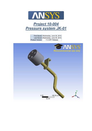
Project 10-004 Pressure system JK-01
•
0 likes•404 views

This document summarizes the finite element analysis of a pressure system (JK-01). It includes the 3D model geometry containing three parts, defined connections between parts, meshing, and static structural analysis applying pressures and supports. The analysis calculated stresses, deformations and resulted in maximum stresses of 12.185 MPa and 1.3683 mm total deformation occurring in the solid parts. Material properties of structural steel and polyethylene were also defined.

Recommended
More Related Content
What's hot
What's hot (17)
Viewers also liked
Viewers also liked (12)
Similar to Project 10-004 Pressure system JK-01
Similar to Project 10-004 Pressure system JK-01 (20)
More from José Manuel Gómez Vega
More from José Manuel Gómez Vega (20)
Project 10-004 Pressure system JK-01
- 1. Project 10-004 Pressure system JK-01 First Saved Wednesday, June 30, 2010 Last Saved Wednesday, June 30, 2010 Product Version 11.0 SP1 Release
- 2. Contents Model o Geometry Parts o Connections Contact Regions o Mesh o Static Structural Analysis Settings Loads Solution Solution Information Results Material Data o Structural Steel o Polyethylene Units TABLE 1 Unit System Metric (mm, kg, N, °C, s, mV, mA) Angle Degrees Rotational Velocity rad/s Model Geometry TABLE 2 Model > Geometry Object Name Geometry State Fully Defined Definition Source D:INGEMEK OFERTAS MEF10-004 Pressure system JK- 01Input_fileInput_filePressure_System.x_t Type Parasolid Length Unit Meters Element Control Program Controlled Display Style Part Color Bounding Box Length X 100, mm Length Y 259,35 mm Length Z 411,03 mm Properties Volume 3,8729e+005 mm³ Mass 1,7159 kg Statistics Bodies 3 Active Bodies 3 Nodes 8041 Elements 3838
- 3. Preferences Import Solid Bodies Yes Import Surface Bodies Yes Import Line Bodies Yes Parameter Processing Yes Personal Parameter Key DS CAD Attribute Transfer No Named Selection Processing No Material Properties Transfer No CAD Associativity Yes Import Coordinate Systems No Reader Save Part File No Import Using Instances Yes Do Smart Update No Attach File Via Temp File No Analysis Type 3-D Mixed Import Resolution None Enclosure and Symmetry Processing Yes TABLE 3 Model > Geometry > Parts Object Name Solid Solid Solid State Meshed Graphics Properties Visible Yes Transparency 1 Definition Suppressed No Material Structural Steel Polyethylene Structural Steel Stiffness Behavior Flexible Nonlinear Material Effects Yes Bounding Box Length X 25, mm 100, mm 50, mm Length Y 177,91 mm 100, mm 118,95 mm Length Z 331,03 mm 90, mm 28, mm Properties Volume 1,4394e+005 mm³ 1,9193e+005 mm³ 51414 mm³ Mass 1,1299 kg 0,18234 kg 0,4036 kg Centroid X 3,9346e-009 mm 4,3844e-014 mm 3,7279e-009 mm Centroid Y 94,615 mm 152,91 mm 203,76 mm Centroid Z -150,5 mm -365,79 mm -234,04 mm Moment of Inertia Ip1 12775 kg·mm² 352,35 kg·mm² 496,29 kg·mm² Moment of Inertia Ip2 11579 kg·mm² 352,35 kg·mm² 98,14 kg·mm² Moment of Inertia Ip3 1312,4 kg·mm² 338,69 kg·mm² 567,27 kg·mm² Statistics Nodes 3941 1788 2312 Elements 1924 838 1076
- 4. FIGURE 1 Model > Geometry > Figure Connections TABLE 4 Model > Connections Object Name Connections State Fully Defined Auto Detection Generate Contact On Update Yes Tolerance Type Slider Tolerance Slider 0, Tolerance Value 1,2405 mm Face/Face Yes Face/Edge No Edge/Edge No Priority Include All Same Body Grouping Yes Revolute Joints Yes Fixed Joints Yes Transparency Enabled Yes
- 5. TABLE 5 Model > Connections > Contact Regions Object Name Contact Region No Separation - Solid To Solid State Fully Defined Scope Scoping Method Geometry Selection Contact 1 Face Target 1 Face Contact Bodies Solid Target Bodies Solid Definition Type Bonded No Separation Scope Mode Automatic Behavior Symmetric Suppressed No Advanced Formulation Pure Penalty Normal Stiffness Program Controlled Update Stiffness Never Thermal Conductance Program Controlled Pinball Region Program Controlled Mesh TABLE 6 Model > Mesh Object Name Mesh State Solved Defaults Physics Preference Mechanical Relevance 0 Advanced Relevance Center Coarse Element Size Default Shape Checking Standard Mechanical Solid Element Midside Nodes Program Controlled Straight Sided Elements No Initial Size Seed Active Assembly Smoothing Low Transition Fast Statistics Nodes 8041 Elements 3838
- 6. Static Structural TABLE 7 Model > Analysis Object Name Static Structural State Fully Defined Definition Physics Type Structural Analysis Type Static Structural Options Reference Temp 22, °C TABLE 8 Model > Static Structural > Analysis Settings Object Name Analysis Settings State Fully Defined Step Controls Number Of Steps 1, Current Step Number 1, Step End Time 1, s Auto Time Stepping Program Controlled Solver Controls Solver Type Program Controlled Weak Springs Program Controlled Large Deflection Off Inertia Relief Off Nonlinear Controls Force Convergence Program Controlled Moment Convergence Program Controlled Displacement Convergence Program Controlled Rotation Convergence Program Controlled Line Search Program Controlled Output Controls Calculate Stress Yes Calculate Strain Yes Calculate Results At All Time Points Analysis Data Management Solver Files Directory D:INGEMEKSOLUCIONES MEFStatic Structural10-004 Pressure system JK-01 Future Analysis None Save ANSYS db No Delete Unneeded Files Yes Nonlinear Solution No
- 7. TABLE 9 Model > Static Structural > Loads Object Name Pressure Pressure 2 Fixed Support Cylindrical Support Frictionless Support State Fully Defined Scope Scoping Method Geometry Selection Geometry 5 Faces 3 Faces 1 Face Definition Define By Normal To Type Pressure Fixed Support Cylindrical Support Frictionless Support Magnitude 1, MPa (ramped) 0,2 MPa (ramped) Suppressed No Radial Fixed Axial Fixed Tangential Fixed FIGURE 2 Model > Static Structural > Pressure
- 8. FIGURE 3 Model > Static Structural > Pressure 2 Solution TABLE 10 Model > Static Structural > Solution Object Name Solution State Solved Adaptive Mesh Refinement Max Refinement Loops 1, Refinement Depth 2, TABLE 11 Model > Static Structural > Solution > Solution Information Object Name Solution Information State Solved Solution Information Solution Output Solver Output Newton-Raphson Residuals 0 Update Interval 2,5 s Display Points All
- 9. TABLE 12 Model > Static Structural > Solution > Results Object Name Equivalent Stress Total Deformation Total Deformation (cámara expansión) Total Deformation (tubo) Total Deformation (contacto chapa) State Solved Scope Geometry All Bodies 1 Body Definition Type Equivalent (von-Mises) Stress Total Deformation Display Time End Time Results Minimum 7,5136e-003 MPa 0, mm 9,6999e-003 mm 0, mm Maximum 12,185 MPa 1,3683 mm 3,7526e-002 mm 2,0645e-002 mm Minimum Occurs On Solid Maximum Occurs On Solid Information Time 1, s Load Step 1 Substep 1 Iteration Number 1
- 10. FIGURE 4 Model > Static Structural > Solution > Equivalent Stress > Figure
- 11. FIGURE 5 Model > Static Structural > Solution > Total Deformation > Figure
- 12. FIGURE 6 Model > Static Structural > Solution > Total Deformation (cámara expansión) > Figure
- 13. FIGURE 7 Model > Static Structural > Solution > Total Deformation (tubo) > Figure
- 14. FIGURE 8 Model > Static Structural > Solution > Total Deformation (contacto chapa) > Figure TABLE 13 Model > Static Structural > Solution > Results Object Name Equivalent Stress (cámara expansión) Equivalent Stress (tubo) Equivalent Stress (contacto chapa) State Solved Scope Geometry 1 Body Definition Type Equivalent (von-Mises) Stress Display Time End Time Results Minimum 0,12764 MPa 0,51189 MPa 7,5136e-003 MPa Maximum 8,8161 MPa 12,185 MPa 6,3029 MPa Information Time 1, s Load Step 1 Substep 1 Iteration Number 1
- 15. FIGURE 9 Model > Static Structural > Solution > Equivalent Stress (cámara expansión) > Figure
- 16. FIGURE 10 Model > Static Structural > Solution > Equivalent Stress (tubo) > Figure
- 17. FIGURE 11 Model > Static Structural > Solution > Equivalent Stress (contacto chapa) > Figure Material Data Structural Steel TABLE 14 Structural Steel > Constants Structural Young's Modulus 2,e+005 MPa Poisson's Ratio 0,3 Density 7,85e-006 kg/mm³ Thermal Expansion 1,2e-005 1/°C Tensile Yield Strength 250, MPa Compressive Yield Strength 250, MPa Tensile Ultimate Strength 460, MPa Compressive Ultimate Strength 0, MPa Thermal Thermal Conductivity 6,05e-002 W/mm·°C Specific Heat 434, J/kg·°C Electromagnetics Relative Permeability 10000 Resistivity 1,7e-004 Ohm·mm
- 18. FIGURE 12 Structural Steel > Alternating Stress TABLE 15 Structural Steel > Alternating Stress > Property Attributes Interpolation Log-Log Mean Curve Type Mean Stress TABLE 16 Structural Steel > Alternating Stress > Alternating Stress Curve Data Mean Value MPa 0, TABLE 17 Structural Steel > Alternating Stress > Alternating Stress vs. Cycles Cycles Alternating Stress MPa 10, 3999, 20, 2827, 50, 1896, 100, 1413, 200, 1069, 2000, 441, 10000 262, 20000 214, 1,e+005 138, 2,e+005 114, 1,e+006 86,2
- 19. FIGURE 13 Structural Steel > Strain-Life Parameters TABLE 18 Structural Steel > Strain-Life Parameters > Property Attributes Display Curve Type Strain-Life TABLE 19 Structural Steel > Strain-Life Parameters > Strain-Life Parameters Strength Coefficient MPa 920, Strength Exponent -0,106 Ductility Coefficient 0,213 Ductility Exponent -0,47 Cyclic Strength Coefficient MPa 1000, Cyclic Strain Hardening Exponent 0,2 Polyethylene TABLE 20 Polyethylene > Constants Structural Young's Modulus 1100, MPa Poisson's Ratio 0,42 Density 9,5e-007 kg/mm³ Thermal Expansion 2,3e-004 1/°C Tensile Yield Strength 25, MPa Compressive Yield Strength 0, MPa Tensile Ultimate Strength 33, MPa Compressive Ultimate Strength 0, MPa Thermal Thermal Conductivity 2,8e-004 W/mm·°C Specific Heat 296, J/kg·°C