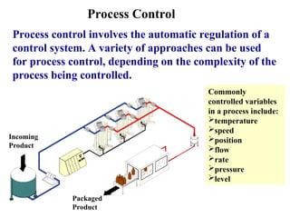
Process control involves the automatic regulation of a control system. A variety of approaches can be used for process control, depending on the complexity of the process being controlled.
Process Control
Process controlinvolves the automatic regulation of a
control system. A variety of approaches can be used
for process control, depending on the complexity of the
process being controlled.
Incoming
Product
Packaged
Product
Commonly
controlled variables
in a process include:
temperature
speed
position
flow
rate
pressure
level
3.
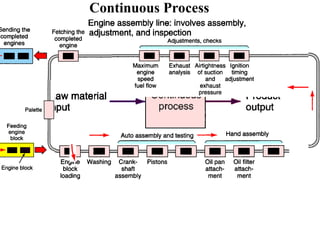
Continuous Process
A continuousprocess is one in which raw materials
enter one of the system and the finished product comes
out the other end of the system; the process itself runs
continuously.
In many cases parts are mounted sequentially, in an
assembly line fashion, through a series of stations. Units
being assembled are moved from station to station using
a transporter mechanism, such as a conveyor. A specific
assembly may utilize only manual operations, or it may
include machine operations.
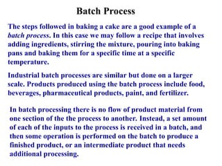
Batch Process
The stepsfollowed in baking a cake are a good example of a
batch process. In this case we may follow a recipe that involves
adding ingredients, stirring the mixture, pouring into baking
pans and baking them for a specific time at a specific
temperature.
Industrial batch processes are similar but done on a larger
scale. Products produced using the batch process include food,
beverages, pharmaceutical products, paint, and fertilizer.
In batch processing there is no flow of product material from
one section of the the process to another. Instead, a set amount
of each of the inputs to the process is received in a batch, and
then some operation is performed on the batch to produce a
finished product, or an intermediate product that needs
additional processing.
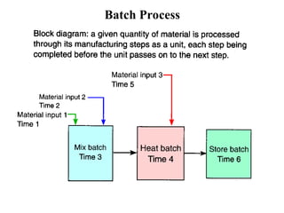
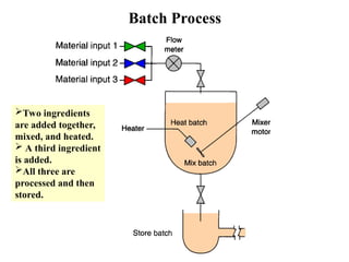
Batch Process
Two ingredients
areadded together,
mixed, and heated.
A third ingredient
is added.
All three are
processed and then
stored.
8.
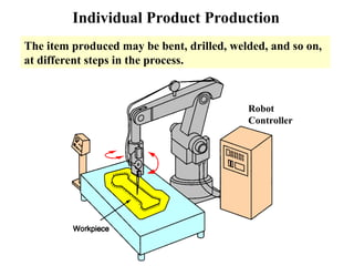
Individual Product Production
Theindividual, or discrete, product control production
process is the most common of all processing systems.
With this manufacturing process, a series of operations
produces a useful output product.
The workpiece is normally a discrete part that must be
handled on an individual basis.
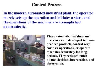
Control Process
In themodern automated industrial plant, the operator
merely sets up the operation and initiates a start, and
the operations of the machine are accomplished
automatically.
These automatic machines and
processes were developed to mass-
produce products, control very
complex operations, or operate
machines accurately for long
periods. They replaced much
human decision, intervention, and
observation.
11.
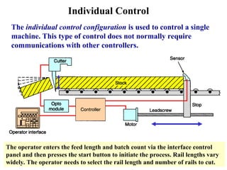
Individual Control
The individualcontrol configuration is used to control a single
machine. This type of control does not normally require
communications with other controllers.
The operator enters the feed length and batch count via the interface control
panel and then presses the start button to initiate the process. Rail lengths vary
widely. The operator needs to select the rail length and number of rails to cut.
12.
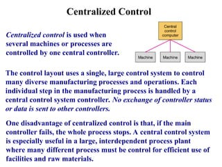
Centralized Control
Centralized controlis used when
several machines or processes are
controlled by one central controller.
The control layout uses a single, large control system to control
many diverse manufacturing processes and operations. Each
individual step in the manufacturing process is handled by a
central control system controller. No exchange of controller status
or data is sent to other controllers.
One disadvantage of centralized control is that, if the main
controller fails, the whole process stops. A central control system
is especially useful in a large, interdependent process plant
where many different process must be control for efficient use of
facilities and raw materials.
13.
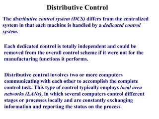
Distributive Control
The distributivecontrol system (DCS) differs from the centralized
system in that each machine is handled by a dedicated control
system.
Each dedicated control is totally independent and could be
removed from the overall control scheme if it were not for the
manufacturing functions it performs.
Distributive control involves two or more computers
communicating with each other to accomplish the complete
control task. This type of control typically employs local area
networks (LANs), in which several computers control different
stages or processes locally and are constantly exchanging
information and reporting the status on the process
14.
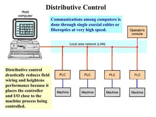
Distributive Control
Distributive control
drasticallyreduces field
wiring and heightens
performance because it
places the controller
and I/O close to the
machine process being
controlled.
Communications among computers is
done through single coaxial cables or
fiberoptics at very high speed.
15.
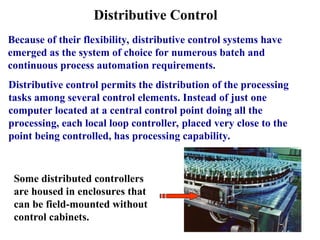
Distributive Control
Because oftheir flexibility, distributive control systems have
emerged as the system of choice for numerous batch and
continuous process automation requirements.
Distributive control permits the distribution of the processing
tasks among several control elements. Instead of just one
computer located at a central control point doing all the
processing, each local loop controller, placed very close to the
point being controlled, has processing capability.
Some distributed controllers
are housed in enclosures that
can be field-mounted without
control cabinets.
16.
Structure Of ControlSystems
A process control system can be defined as the functions
and operations necessary to change a material either
physically or chemically.
Process control normally refers to the manufacturing or
processing of products in industry.
In the case of a programmable controller, the process or
machine is operated and supervised under control of
the user program.
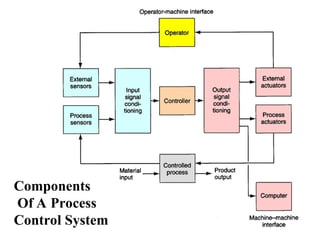
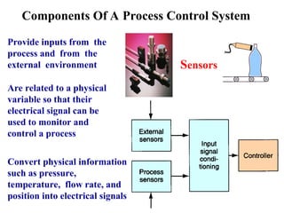
Components Of AProcess Control System
Provide inputs from the
process and from the
external environment
Are related to a physical
variable so that their
electrical signal can be
used to monitor and
control a process
Sensors
Convert physical information
such as pressure,
temperature, flow rate, and
position into electrical signals
19.
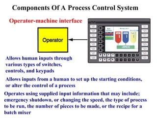
Allows inputs froma human to set up the starting conditions,
or alter the control of a process
Allows human inputs through
various types of switches,
controls, and keypads
Components Of A Process Control System
Operator-machine interface
Operates using supplied input information that may include;
emergency shutdown, or changing the speed, the type of process
to be run, the number of pieces to be made, or the recipe for a
batch mixer
20.
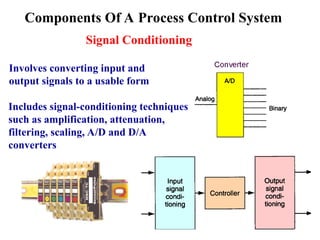
Involves converting inputand
output signals to a usable form
Includes signal-conditioning techniques
such as amplification, attenuation,
filtering, scaling, A/D and D/A
converters
Components Of A Process Control System
Signal Conditioning
21.
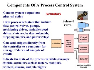
Convert system outputinto
physical action
Have process actuators that include
flow control valves, pumps,
positioning drives, variable speed
drives, clutches, brakes, solenoids,
stepping motors, and power relays
Actuators
Components Of A Process Control System
Solenoid
Valve
Can send outputs directly from
the controller to a computer for
storage of data and analysis of
results
Indicate the state of the process variables through
external actuators such as meters, monitors,
printers, alarms, and pilot lights
22.
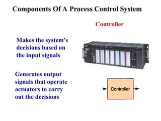
Components Of AProcess Control System
Controller
Makes the system’s
decisions based on
the input signals
Generates output
signals that operate
actuators to carry
out the decisions
23.
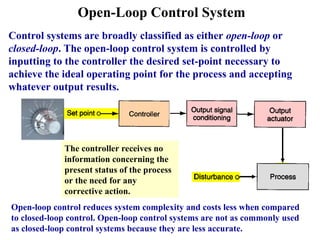
Open-Loop Control System
Controlsystems are broadly classified as either open-loop or
closed-loop. The open-loop control system is controlled by
inputting to the controller the desired set-point necessary to
achieve the ideal operating point for the process and accepting
whatever output results.
The controller receives no
information concerning the
present status of the process
or the need for any
corrective action.
Open-loop control reduces system complexity and costs less when compared
to closed-loop control. Open-loop control systems are not as commonly used
as closed-loop control systems because they are less accurate.
24.
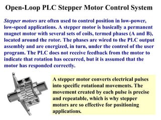
Open-Loop PLC StepperMotor Control System
Stepper motors are often used to control position in low-power,
low-speed applications. A stepper motor is basically a permanent
magnet motor with several sets of coils, termed phases (A and B),
located around the rotor. The phases are wired to the PLC output
assembly and are energized, in turn, under the control of the user
program. The PLC does not receive feedback from the motor to
indicate that rotation has occurred, but it is assumed that the
motor has responded correctly.
A stepper motor converts electrical pulses
into specific rotational movements. The
movement created by each pulse is precise
and repeatable, which is why stepper
motors are so effective for positioning
applications.
25.
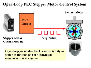
Stepper Motor
Output Module
StepperMotor
Open-Loop PLC Stepper Motor Control System
PLC
Output
Step Pulses
Open-loop, or nonfeedback, control is only as
stable as the load and the individual
components of the system.
26.
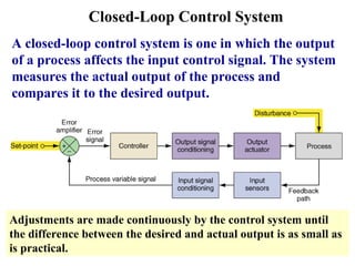
Closed-Loop Control System
Aclosed-loop control system is one in which the output
of a process affects the input control signal. The system
measures the actual output of the process and
compares it to the desired output.
Adjustments are made continuously by the control system until
the difference between the desired and actual output is as small as
is practical.
27.
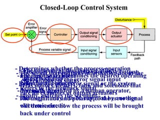
Closed-Loop Control System
-Theinput that determines the desired operating
point for the process
- Normally provided by a human operator,
although it may also be supplied by another
electronic circuit
- The signal that contains information about the
current process status
- Refers to the feedback signal
- Ideally, matches the set point
- Determines whether the process operation
matches the set point
- Referred to as the error signal or the system
deviation signal
- The magnitude and polarity of the error signal
will determine how the process will be brought
back under control
- Produces the appropriate corrective output
signal based on the error signal input
- The component that directly affects a
process change
- Has motors, heaters, fans, and solenoids that
are all examples of output actuators
28.
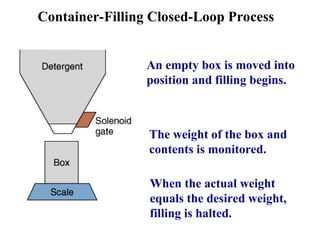
Container-Filling Closed-Loop Process
Anempty box is moved into
position and filling begins.
The weight of the box and
contents is monitored.
When the actual weight
equals the desired weight,
filling is halted.
29.
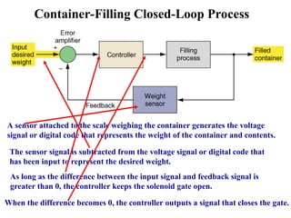
Container-Filling Closed-Loop Process
Asensor attached to the scale weighing the container generates the voltage
signal or digital code that represents the weight of the container and contents.
The sensor signal is subtracted from the voltage signal or digital code that
has been input to represent the desired weight.
As long as the difference between the input signal and feedback signal is
greater than 0, the controller keeps the solenoid gate open.
When the difference becomes 0, the controller outputs a signal that closes the gate.
30.
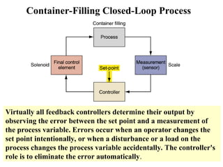
Container-Filling Closed-Loop Process
Virtuallyall feedback controllers determine their output by
observing the error between the set point and a measurement of
the process variable. Errors occur when an operator changes the
set point intentionally, or when a disturbance or a load on the
process changes the process variable accidentally. The controller's
role is to eliminate the error automatically.
31.
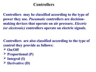
Controllers
Controllers may beclassified according to the type of
power they use. Pneumatic controllers are decision-
making devices that operate on air pressure. Electric
(or electronic) controllers operate on electric signals.
Controllers are also classified according to the type of
control they provide as follows:
On/Off
Proportional (P)
Integral (I)
Derivative (D)
32.
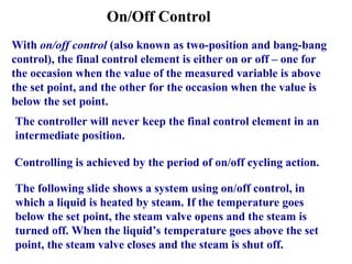
On/Off Control
With on/offcontrol (also known as two-position and bang-bang
control), the final control element is either on or off – one for
the occasion when the value of the measured variable is above
the set point, and the other for the occasion when the value is
below the set point.
The controller will never keep the final control element in an
intermediate position.
Controlling is achieved by the period of on/off cycling action.
The following slide shows a system using on/off control, in
which a liquid is heated by steam. If the temperature goes
below the set point, the steam valve opens and the steam is
turned off. When the liquid’s temperature goes above the set
point, the steam valve closes and the steam is shut off.
33.
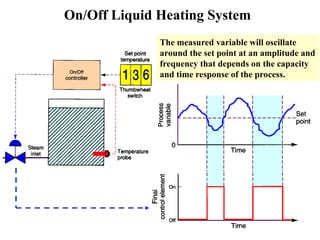
On/Off Liquid HeatingSystem
The measured variable will oscillate
around the set point at an amplitude and
frequency that depends on the capacity
and time response of the process.
34.
On/Off Control
A deadbandis usually established around the set point of
an on/off controller.
The deadband of the controller is usually a selectable
value that determines the error range above and below
the set point that will not produce an output as long as
the process variable is within the set limits.
The inclusion of a deadband eliminates any hunting by
the control device around the set point. Hunting occurs
when minor adjustments of the controlled position are
continuously made due to minor fluctuations.
35.
Proportional Control (P-Controller)
Proportionalcontrols are designed to eliminate the
hunting or cycling associated with on/off control.
Proportional controls allows the final control element
to take intermediate positions between on and off.
This permits analog control of the final control
element to vary the amount of energy to the process,
depending on how much the value of the measured
variable has shifted from the desired value.
The proportional controller allows tighter control of
the process variable because its output can take on
any value between fully on and fully off, depending on
the magnitude of the error signal.
36.
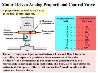
Motor-Driven Analog ProportionalControl Valve
A proportional control valve is used
as the final control element.
The valve receives an input current between 4 mA and 20 mA from the
controller; in response it provides a linear movement of the valve.
A value of 4 mA corresponds to minimum value (often 0) and 20 mA
corresponds to maximum value (full scale). The 4 mA lower limit allows the
system to detect opens. If the circuit is open, 0 mA would result, and the
system can issue an alarm.
37.
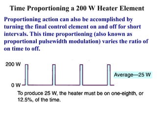
Time Proportioning a200 W Heater Element
Proportioning action can also be accomplished by
turning the final control element on and off for short
intervals. This time proportioning (also known as
proportional pulsewidth modulation) varies the ratio of
on time to off.
38.
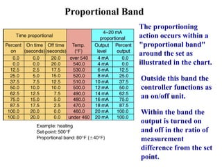
Proportional Band
The proportioning
actionoccurs within a
"proportional band"
around the set as
illustrated in the chart.
Outside this band the
controller functions as
an on/off unit.
Within the band the
output is turned on
and off in the ratio of
measurement
difference from the set
point.
39.
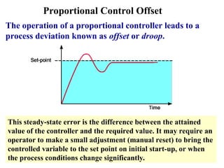
Proportional Control Offset
Theoperation of a proportional controller leads to a
process deviation known as offset or droop.
This steady-state error is the difference between the attained
value of the controller and the required value. It may require an
operator to make a small adjustment (manual reset) to bring the
controlled variable to the set point on initial start-up, or when
the process conditions change significantly.
40.
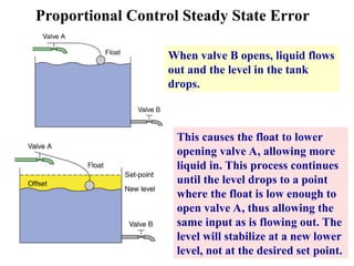
Proportional Control SteadyState Error
When valve B opens, liquid flows
out and the level in the tank
drops.
This causes the float to lower
opening valve A, allowing more
liquid in. This process continues
until the level drops to a point
where the float is low enough to
open valve A, thus allowing the
same input as is flowing out. The
level will stabilize at a new lower
level, not at the desired set point.
41.
Integral Control (I-Controller)
Theintegral action, sometimes termed reset action,
responds to the size and time duration of the error
signal.
With integral action, the controller output is
proportional to the amount of time the error is
present. Integral action eliminates offset.
Integral controllers tend to respond slowly at first, but
over a long period of time they tend to eliminate errors.
The integral controller eliminates the steady-state
error, but may make the transient response worse.
42.
Derivative Control (D-Controller)
Thederivative controller responds to the speed at which
the error signal is changing – that is, the greater the
error change, the greater the correcting output.
The derivative action is measured in terms of time.
With derivative action, the controller output is
proportional to the rate of change of the measurement
or error.
The derivative mode controller is never used alone.
With sudden changes in the system the derivative
controller will compensate the output fast.
43.
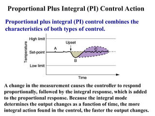
Proportional Plus Integral(PI) Control Action
Proportional plus integral (PI) control combines the
characteristics of both types of control.
A change in the measurement causes the controller to respond
proportionally, followed by the integral response, which is added
to the proportional response. Because the integral mode
determines the output changes as a function of time, the more
integral action found in the control, the faster the output changes.
44.
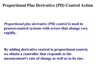
Proportional Plus Derivative(PD) Control Action
Proportional plus derivative (PD) control is used in
process-control systems with errors that change very
rapidly.
By adding derivative control to proportional control,
we obtain a controller that responds to the
measurement's rate of change as well as to its size.
45.
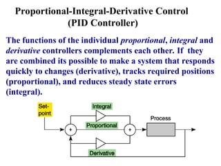
Proportional-Integral-Derivative Control
(PID Controller)
Thefunctions of the individual proportional, integral and
derivative controllers complements each other. If they
are combined its possible to make a system that responds
quickly to changes (derivative), tracks required positions
(proportional), and reduces steady state errors
(integral).
46.
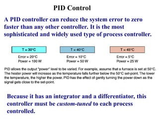
PID Control
A PIDcontroller can reduce the system error to zero
faster than any other controller. It is the most
sophisticated and widely used type of process controller.
Because it has an integrator and a differentiator, this
controller must be custom-tuned to each process
controlled.
47.
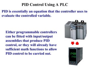
PID Control UsingA PLC
Either programmable controllers
can be fitted with input/output
assemblies that produce PID
control, or they will already have
sufficient math functions to allow
PID control to be carried out.
PID is essentially an equation that the controller uses to
evaluate the controlled variable.
48.
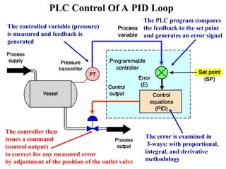
PLC Control OfA PID Loop
The controlled variable (pressure)
is measured and feedback is
generated
The PLC program compares
the feedback to the set point
and generates an error signal
The error is examined in
3-ways: with proportional,
integral, and derivative
methodology
The controller then
issues a command
(control output)
to correct for any measured error
by adjustment of the position of the outlet valve
49.
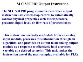
SLC 500 PIDOutput Instruction
The SLC 500 PID programmable controller output
instruction uses closed-loop control to automatically
control physical properties such as temperature,
pressure, liquid level, or flow rate of process loops.
This instruction normally reads data from an analog
input module, processes this information through an
algorithm, and provides an output to an analog output
module as a response to effectively hold a process
variable at a desired set point. This task makes the
instruction one of the most complex available for PLCs.
50.
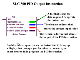
A file thatstores the
data required to operate
the instruction
The element address that
stores the process input value
The element address that stores
the output of the PID instruction
Double click setup screen on the instruction to bring up
a display that prompts you for other parameters you
must enter to fully program the PID instruction.
SLC 500 PID Output Instruction
51.
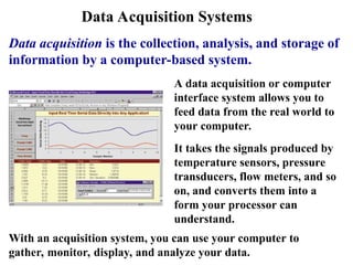
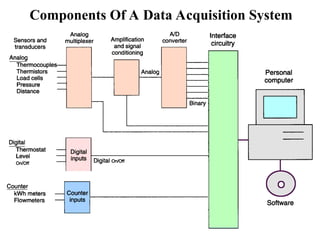
Data Acquisition Systems
Dataacquisition is the collection, analysis, and storage of
information by a computer-based system.
A data acquisition or computer
interface system allows you to
feed data from the real world to
your computer.
It takes the signals produced by
temperature sensors, pressure
transducers, flow meters, and so
on, and converts them into a
form your processor can
understand.
With an acquisition system, you can use your computer to
gather, monitor, display, and analyze your data.
52.
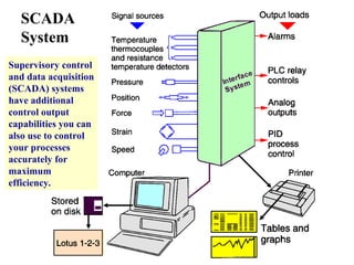
SCADA
System
Supervisory control
and dataacquisition
(SCADA) systems
have additional
control output
capabilities you can
also use to control
your processes
accurately for
maximum
efficiency.
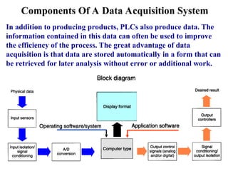
Components Of AData Acquisition System
In addition to producing products, PLCs also produce data. The
information contained in this data can often be used to improve
the efficiency of the process. The great advantage of data
acquisition is that data are stored automatically in a form that can
be retrieved for later analysis without error or additional work.
55.
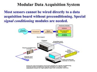
Modular Data AcquisitionSystem
Most sensors cannot be wired directly to a data
acquisition board without preconditioning. Special
signal conditioning modules are needed.