Matrix is a single-source supplier that provides expertise in pressure vessel design and evaluation. They have experience with vessel and tank codes like ASME Section VIII Divisions 1 and 2, performing finite element analysis, nozzle and attachment design, support designs, seismic and other calculations, and custom evaluations to specialized industry standards. Matrix can utilize various software and perform hand calculations, finite element analysis, or evaluations to solve difficult pressure vessel problems.
Design by Analysis - A general guideline for pressure vesselAnalyzeForSafety
This presentation file is provided by Mr. Ghanbari and published under permission.
The presentation gives an introduction and general guideline for pressure vessel design by analysis.
The “design by analysis” procedures are intended to guard against eight possible pressure vessel failure modes by performing a detailed stress analysis of the vessel with the sufficient design factors. The failure modes are:
1.excessive elastic deformation, including elastic instability,
2.excessive plastic deformation,
3.brittle fracture,
4.stress rupture/creep deformation (inelastic),
5.plastic instability - incremental collapse,
6.high strain - low cycle fatigue,
7.stress corrosion, and
8.corrosion fatigue
Most of the “design by analysis” procedures that are given in ASME BPVC relate to designs based on “elastic analysis.”
The design-by-analysis requirements are organized based on protection against the failure modes listed below. The component shall be evaluated for each applicable failure mode. If multiple assessment procedures are provided for a failure mode, only one of these procedures must be satisfied to qualify the design of a component.
a)All pressure vessels within the scope of this Division, irrespective of size or pressure, shall be provided with protection against overpressure in accordance with the requirements of this Part.
b)Protection Against Plastic Collapse – these requirements apply to all components where the thickness and configuration of the component is established using design-by-analysis rules.
c)Protection Against Local Failure – these requirements apply to all components where the thickness and configuration of the component is established using design-by-analysis rules. It is not necessary to evaluate the local strain limit criterion if the component design is in accordance with Part 4 (i.e. component wall thickness and weld detail per paragraph 4.2).
d)Protection Against Collapse From Buckling – these requirements apply to all components where the thickness and configuration of the component is established using design-by-analysis rules and the applied loads result in a compressive stress field.
e)Protection Against Failure From Cyclic Loading – these requirements apply to all components where the thickness and configuration of the component is established using design-by-analysis rules and the applied loads are cyclic. In addition, these requirements can also be used to qualify a component for cyclic loading where the thickness and size of the component are established using the design-by-rule requirements of Part 4.
Intergraph® cadworx® & analysis solutions offerings work together to give you the power to
tackle the most challenging and complex projects with greater ease and superior results never
before achievable. chosen by more than 80 percent of leading plant engineering companies and
owner operators from around the world, cadworx & analysis solutions are:
• Easy to use
• Flexible
• Scalable
• Trusted to deliver accurate, reliable results
PV Elite é uma solução completa para projeto, análise e avaliação de vasos e trocadores de calor. Os usuários do PV Elite têm equipamentos projetados para usos extremos e em tempo rápido, com perfeição e rentabilidade.
Para maiores informações:
www.natecnologia.com.br
Resablok multidirectional system presentation of Resa GroupGrupo Resa
Resablok is a multilevel and multidirectional scaffolding, composed of a set of standard tubular elements assembled together by means of a knot and wedge system, which results in a light and totally rigid scaffolding structure.
The surface finish of all Resablok scaffolding elements is hot-dip galvanized. It is suitable for work on facades, towers, access ladders, perimeter scaffolding, volume scaffolding, falsework, facade stabilizers, hanging and cantilevered, temporary roofs, etc.
Our Resablok scaffolds are patented and have Product Certificates in accordance with the UNE-EN12811-1, UNE-EN12811-2 and UNE-EN12811-3 Standards. With a reduced number of components. Simple, Light, Durable.
How to regain design freedom and source the perfect linear guide with Extrude...Design World
Linear guides are one of the most important components required for the development of automated or computer controlled equipment. 3D printers, CNC routers, and tabletop factories. Machines wouldn’t function without them. During the development phase, most design engineers will survey existing manufacturers for standard linear guide products to incorporate into their projects. Invariably, the designer will need to make compromises in their selection process and accept limited design freedom on purchased products. Perhaps the available guides are too large, require modifications, or have unstable supply quantities.
Extrusion based linear guides provide design freedom and can incorporate additional features to lower the overall complexity of a machine. They are supplied reliably in low quantities with the perfect design features. Extrusion designs can incorporate locations for attaching gear racks, linear tape encoders, cable carriers, or wire ducts and secondary machining such as threaded end holes allow for simplified assembly. Integrate many features into your perfect extruded profile guide.
View this webinar to learn:
-How hardened steel vee guide track can be incorporated into extruded
-About the process and timeline for developing the perfect extrusion based linear guide.
-About successful industry application examples.
MB Kit Systems utilizes extruded aluminum framing system to design and build mechanical solutions, including linear motion systems, machine safety guarding and specialty enclosures. Mechanical structures built with t-slotted aluminum profile offers a versatile, modular and cost-effective replacement to steel machine framing.
Watch this presentation for a range of mechanical solutions we can design and assembly for your next custom manufacturing solution.
Learn more at www.MBKitSystems.com
GT STRUDL® é um software de sistema CAE (Computer-aided structural engineering) amplamente utilizado em diversas áreas como energia nuclear, segmentos de defesa nuclear, geração de energia convencional, projeto de plantas, estruturas offshore, aplicações navais, engenharia civil e estruturas de infraestrutura. Permite modelagem gráfica, análise estática e dinâmica de elementos finitos, projeto de quadros estruturais, modelagem estrutural, análises não lineares, análises gráficas e gerenciamento de bancos de dados estruturais e de exibição de resultados.
Para maiores informações:
www.natecnologia.com.br
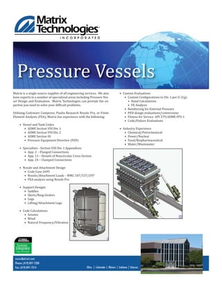
1. Pressure Vessels
Matrix is a single-source supplier of all engineering services. We also
have experts in a number of specialized areas including Pressure Ves-
sel Design and Evaluation. Matrix Technologies can provide the ex-
pertise you need to solve your dif icult problems.
Utilizing Codeware Compress, Paulin Research Nozzle Pro, or Finite
Element Analysis (FEA), Matrix has experience with the following:
• Vessel and Tank Codes
• ASME Section VIII Div. 1
• ASME Section VIII Div. 2
• ASME Section III
• Pressure Equipment Directive (PED)
• Specialties - Section VIII Div. 1 Appendices
• App. 2 - Flanged Connections
• App. 13 – Vessels of Noncircular Cross Section
• App. 24 – Clamped Connections
• Nozzle and Attachment Design
• Code Case 2695
• Nozzle/Attachment Loads – WRC-107/537/297
• FEA analysis using Nozzle Pro
• Support Designs
• Saddles
• Skirts/Ring Girders
• Legs
• Lifting/Attachment Lugs
• Code Calculations
• Seismic
• Wind
• Natural Frequency/Vibration
www.Matrixti.com
Phone: (419) 897-7200
Fax: (419) 897-7214 Ohio | Colorado | Illinois | Indiana | Kansas
• Custom Evaluations
• Custom Con igurations to Div. 1 per U-2(g)
• Hand Calculations
• FE Analysis
• Reinforcing for External Pressure
• PED design evaluations/conversions
• Fitness for Service API 579/ASME FFS-1
• Code/Failure Evaluations
• Industry Experience
• Chemical/Petrochemical
• Power/Nuclear
• Food/Biopharmaceutical
• Water/Wastewater