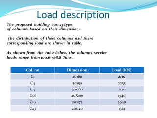
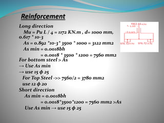
Prepared by
Israa Hanani
Noor Sobuh
Nibal Awwad
Supervisor
Dr: Sami Hijjawi
Outline
1- Introduction and site description.
2- Load description and type of foundation.
3- Design of foundation.
a. single footing
b. mat foundation
c. pile foundation
Introduction and site description
The building foundation or sub structure is that part of a
structure which is placed below the surface of the ground and
which transmits the superstructure load to the underlying soil
ultimately .
It is the part of a structural system that supports and anchors
the superstructure of a building .
Building located Fattouh for Aljnied prison and consists of 7 floors.
Soil type built by architecture is clay soil . And the allowable
bearing capacity is 182 KN/m2.
Based on soil testing, the origin was designed to foundations mat
foundation and under it pile .
Load description
The proposed building has 23 type
of columns based on their dimension .
The distribution of these columns and there
corresponding load are shown in table.
As shown from the table below, the columns service
loads range from 100.6- 578.8 Tons .
Col. no Dimension Load (KN)
C1 20x60 2110
C4 50x50 2235
C17 30x160 2170
C18 20X100 1540
C19 20x175 2940
C23 20x120 1314
Type
Pile
Mate
Single
Design single footing
The dimension of single footing according to applied service load
and bearing capacity of soil as follow :
For column 1 (as an example ) :
Area of footing = Pall / Q all
= 2110 / 182 =11.6 m2 (4.5m * 3m)
and repeat it for all column .
From the Fig. we see the overlap between the adjacent footing, so the single
footing doesn't fit for this project.
Mat Foundation
Area of mat footing = 579.4 m2
2) Calculate the eccentricity in X and Y directions
ex = YP – YG = 6.684 – 6.8 = -0.114 m
ey = XP – XG = 20.64 – 21.3 = -0.66 m
column
Name
Service
KN)
)
load
Yi Xi P*Xi P*Yi
C1 2110 11.65 39.9 84189 24581.5
Calculate the center of loading that applied at
columns
(col. 1 as an example) :
After that
1) We calculate center of loads
X p= 1353055.8/ 65563 = 20.64 m
Yp=438341.64 / 65563 = 6.685 m
We take internal stripe in y- direction with width 4.53m as shown in
fig. above
Total soil pressure = 4.53* 13.45 *113.13
=6892.8 KN
∑ col loads = 1540 + 2938 + 2340
= 6818 KN
q= -(Q/A) – (My X/ Iy ) – (Mxy/Ix)
Ix = bh3 / 12
= 8928.87 m4
Iy = 87616.6 m 4
Mx = Q ex = 7605.5 KN.m
My = 35854.5 KN.m
q = 125 < 182 KN/m2 ……. Ok
Shea force diagram
From the figure of shear and moment we do the
checks and compare the result to the max. value
Mu = 3615.5 KN.m
Calculate the thickness of mat footing:-
Width of strip 4.53m
Vu = 1957.7 KN
Assume
•D =800 mm h =900 mm
Wide beam shear check :-
Ø vc = (0.75 / 6) (28 ) 0.5 *4530 * 800 / 1000
= 2397.1.3 KN > Vu ok
Mu = 3615.5 KN.m
ρ = 0.0034 > ρ min ok
As = ρ bd
= 0.0034 * 4530 *800
= 12304.6 mm 2 > As min 1Ø 25 / 200 mm
As min = 0.0018bh = 1296.0 mm2
Check Punching :-
Check punching for C 8 :-
Pu = 1.4 * 3230
= 4522 KN
ØVc = ( Ø /3 ) (fc )0.5 bod
= ( 0.75 / 3) (28)0.5(2*1200 + 2* 1200 )
(800 ) /1000
=5503.16 KN > Pu
For columns 11 and 10 we may use
drop panel or increase the amount of
steel to make it ok for punching
A pile is a relatively long columnar
construction element made of
wood, or reinforced concrete, or
metal, or a combination thereof. It is
embedded into soil to receive and
transmit vertical and transmit
vertical and inclined loads into the
soil or to rock below the ground
surface
Use All-Pile program
Total Ultimate Capacity (Down)= 2195.38-kN,
Total Ultimate Capacity (Up)= 2068.05-kN
Total Allowable Capacity (Down)= 731.79-kN,
Total Allowable Capacity (Up)= 761.28-kN
where it's service load equal 5788 KN/m2
Number of Pile
Find the min. length for pile from the equation and
satisfied the min.
Ep RI / Su = 461538
So from table min. length = 11* D = 8.8 m
Assume allowable capacity of a 0.8-m-diameter and
15-m-long pile
Total Allowable Capacity (Down)= 731.79-kN
F=( P/N) +( Mxy/Σyi2) + (Myx/Σxi2) ≤ qall
F= (5788)/N ≤ 731.79 → N=8→ Use 8 Piles
Wide beam shear :
Vu =976.72*2 = 1953.44 KN ϕVc =
0.75(1/6) (√fc) bd /1000 =
0.75(1/6)(√28)(3500)d/1000=
→ d = 850 mm
→ h =1050 mm
For column:
Vu= 7813.8 KN
ϕVc=
0.75(1/3)(√28)*800*(1350*2+1350*2)/1000=
6071KN >7813.8 KN → NOT OK
SO we increase d= 1000 mm , h=1200 mm
ϕVc = 7937 > 7813.8 KN → OK
Long direction
Mu = Pu L / 4 = 1172 KN.m , d= 1000 mm, ρ=
0.617 * 10-3
As = 0.892 *10-3* 3500 * 1000 = 3122 mm2
As min = 0.0018bh
= 0.0018 * 3500 * 1200 = 7560 mm2
For bottom steel > As
→ Use As min
→ use 15 ϕ 25
For Top Steel ->> 7560/2 = 3780 mm2
use 12 ϕ 20
Short direction
As min = 0.0018bh
= 0.0018*3500*1200 = 7560 mm2 >As
Use As min → use 15 ϕ 25
The figure show the distribution of the steel
(a) Show the distribution steel for cap from
analysis and (b) Show the distribution of the
steel for Pile from classification
φ
presentation_41.pptx

presentation_41.pptx

  • 1.
    Prepared by Israa Hanani NoorSobuh Nibal Awwad Supervisor Dr: Sami Hijjawi
  • 2.
    Outline 1- Introduction andsite description. 2- Load description and type of foundation. 3- Design of foundation. a. single footing b. mat foundation c. pile foundation
  • 3.
    Introduction and sitedescription The building foundation or sub structure is that part of a structure which is placed below the surface of the ground and which transmits the superstructure load to the underlying soil ultimately . It is the part of a structural system that supports and anchors the superstructure of a building . Building located Fattouh for Aljnied prison and consists of 7 floors. Soil type built by architecture is clay soil . And the allowable bearing capacity is 182 KN/m2. Based on soil testing, the origin was designed to foundations mat foundation and under it pile .
  • 4.
    Load description The proposedbuilding has 23 type of columns based on their dimension . The distribution of these columns and there corresponding load are shown in table. As shown from the table below, the columns service loads range from 100.6- 578.8 Tons . Col. no Dimension Load (KN) C1 20x60 2110 C4 50x50 2235 C17 30x160 2170 C18 20X100 1540 C19 20x175 2940 C23 20x120 1314
  • 5.
  • 6.
    Design single footing Thedimension of single footing according to applied service load and bearing capacity of soil as follow : For column 1 (as an example ) : Area of footing = Pall / Q all = 2110 / 182 =11.6 m2 (4.5m * 3m) and repeat it for all column . From the Fig. we see the overlap between the adjacent footing, so the single footing doesn't fit for this project.
  • 7.
    Mat Foundation Area ofmat footing = 579.4 m2
  • 8.
    2) Calculate theeccentricity in X and Y directions ex = YP – YG = 6.684 – 6.8 = -0.114 m ey = XP – XG = 20.64 – 21.3 = -0.66 m column Name Service KN) ) load Yi Xi P*Xi P*Yi C1 2110 11.65 39.9 84189 24581.5 Calculate the center of loading that applied at columns (col. 1 as an example) : After that 1) We calculate center of loads X p= 1353055.8/ 65563 = 20.64 m Yp=438341.64 / 65563 = 6.685 m
  • 9.
    We take internalstripe in y- direction with width 4.53m as shown in fig. above Total soil pressure = 4.53* 13.45 *113.13 =6892.8 KN ∑ col loads = 1540 + 2938 + 2340 = 6818 KN q= -(Q/A) – (My X/ Iy ) – (Mxy/Ix) Ix = bh3 / 12 = 8928.87 m4 Iy = 87616.6 m 4 Mx = Q ex = 7605.5 KN.m My = 35854.5 KN.m q = 125 < 182 KN/m2 ……. Ok
  • 10.
  • 11.
    From the figureof shear and moment we do the checks and compare the result to the max. value Mu = 3615.5 KN.m
  • 12.
    Calculate the thicknessof mat footing:- Width of strip 4.53m Vu = 1957.7 KN Assume •D =800 mm h =900 mm Wide beam shear check :- Ø vc = (0.75 / 6) (28 ) 0.5 *4530 * 800 / 1000 = 2397.1.3 KN > Vu ok Mu = 3615.5 KN.m ρ = 0.0034 > ρ min ok As = ρ bd = 0.0034 * 4530 *800 = 12304.6 mm 2 > As min 1Ø 25 / 200 mm As min = 0.0018bh = 1296.0 mm2
  • 13.
    Check Punching :- Checkpunching for C 8 :- Pu = 1.4 * 3230 = 4522 KN ØVc = ( Ø /3 ) (fc )0.5 bod = ( 0.75 / 3) (28)0.5(2*1200 + 2* 1200 ) (800 ) /1000 =5503.16 KN > Pu For columns 11 and 10 we may use drop panel or increase the amount of steel to make it ok for punching
  • 14.
    A pile isa relatively long columnar construction element made of wood, or reinforced concrete, or metal, or a combination thereof. It is embedded into soil to receive and transmit vertical and transmit vertical and inclined loads into the soil or to rock below the ground surface
  • 15.
    Use All-Pile program TotalUltimate Capacity (Down)= 2195.38-kN, Total Ultimate Capacity (Up)= 2068.05-kN Total Allowable Capacity (Down)= 731.79-kN, Total Allowable Capacity (Up)= 761.28-kN
  • 16.
    where it's serviceload equal 5788 KN/m2 Number of Pile Find the min. length for pile from the equation and satisfied the min. Ep RI / Su = 461538 So from table min. length = 11* D = 8.8 m Assume allowable capacity of a 0.8-m-diameter and 15-m-long pile Total Allowable Capacity (Down)= 731.79-kN F=( P/N) +( Mxy/Σyi2) + (Myx/Σxi2) ≤ qall F= (5788)/N ≤ 731.79 → N=8→ Use 8 Piles
  • 18.
    Wide beam shear: Vu =976.72*2 = 1953.44 KN ϕVc = 0.75(1/6) (√fc) bd /1000 = 0.75(1/6)(√28)(3500)d/1000= → d = 850 mm → h =1050 mm
  • 19.
    For column: Vu= 7813.8KN ϕVc= 0.75(1/3)(√28)*800*(1350*2+1350*2)/1000= 6071KN >7813.8 KN → NOT OK SO we increase d= 1000 mm , h=1200 mm ϕVc = 7937 > 7813.8 KN → OK
  • 20.
    Long direction Mu =Pu L / 4 = 1172 KN.m , d= 1000 mm, ρ= 0.617 * 10-3 As = 0.892 *10-3* 3500 * 1000 = 3122 mm2 As min = 0.0018bh = 0.0018 * 3500 * 1200 = 7560 mm2 For bottom steel > As → Use As min → use 15 ϕ 25 For Top Steel ->> 7560/2 = 3780 mm2 use 12 ϕ 20 Short direction As min = 0.0018bh = 0.0018*3500*1200 = 7560 mm2 >As Use As min → use 15 ϕ 25
  • 21.
    The figure showthe distribution of the steel (a) Show the distribution steel for cap from analysis and (b) Show the distribution of the steel for Pile from classification φ