SlideShare a Scribd company logo
1 of 348
Fundamentals of Predictive Maintenance

Introduction To
Predictive Maintenance

January 2008
Introduction
Fundamentals of Predictive Maintenance

Ejercicios de ¿Qué Pasa Si? y de Diagnóstico y Solución de Problemas

2

• The purpose of this course is to
introduce and provide individuals
with an overview of predictive
maintenance and a basic
understanding of the methods and
tools required..
Objectives

Ejercicios de ¿Qué Pasa Si? y de Diagnóstico y Solución de Problemas

Fundamentals of Predictive Maintenance

• This course will present the following topics:

3

– Define predictive maintenance programs
– Define maintenance planning requirements and
review Critical Path Method (CPM)
– Examine the principles of Vibration Theory and
Analysis.
– Examine the basics of Lubrication and Analysis
(Tribology).
– Examine the basics of Ultrasonic Analysis
– Examine the basics of Thermographic Analysis
– Examine the principles of Electrical Insulation
Testing
– Define inspection and performance
measurement techniques
Agenda

Fundamentals of Predictive Maintenance

Ejercicios de ¿Qué Pasa Si? y de Diagnóstico y Solución de Problemas

4

•
•
•
•
•

Predictive Maintenance
Maintenance Planning
Vibration Analysis
Performance Monitoring
Thermal Analysis
Agenda

Ejercicios de ¿Qué Pasa Si? y de Diagnóstico y Solución de Problemas

Fundamentals of Predictive Maintenance

•

5

•
•
•
•
•

Lubrication and Tribology (Fluid
Analysis)
Non-destructive Testing and Inspection
Ultrasonic Measurement
Insulation Testing
Balancing
Review
Fundamentals of Predictive Maintenance

Predictive
Maintenance
Objectives

Ejercicios de ¿Qué Pasa Si? y de Diagnóstico y Solución de Problemas

Fundamentals of Predictive Maintenance

•

7

– Define preventive maintenance.
– Define predictive maintenance.
– Define patterns of failure
– Define condition monitoring
Terms

Fundamentals of Predictive Maintenance

Ejercicios de ¿Qué Pasa Si? y de Diagnóstico y Solución de Problemas

8

•
•
•
•

PM means Preventive Maintenance
PdM means Predictive Maintenance
PPM or P/PM means
CMMS means Computerized
Maintenance Management System
How to View Maintenance
Fundamentals of Predictive Maintenance

Ejercicios de ¿Qué Pasa Si? y de Diagnóstico y Solución de Problemas

9

•
•
•
•

Engineering
Economic
Management
What else?
PM

Fundamentals of Predictive Maintenance

Ejercicios de ¿Qué Pasa Si? y de Diagnóstico y Solución de Problemas

10

• PM (Preventive Maintenance) is a series
of tasks which are performed at
sequence of time, quantity of production,
equipment hours, mileage or condition
for the purpose of:
– Extending equipment life
– Detect critical wear or impending
breakdown
PdM

Fundamentals of Predictive Maintenance

Ejercicios de ¿Qué Pasa Si? y de Diagnóstico y Solución de Problemas

11

• PdM (Predictive Maintenance) is any
inspection carried out with technological
tools to detect when failures will occur.
Misconceptions about PM
Fundamentals of Predictive Maintenance

Ejercicios de ¿Qué Pasa Si? y de Diagnóstico y Solución de Problemas

12

• PM is the only way to determine when
and what will break down.
• PM systems are the same
• PM is extra work/costs more.
• Unskilled people can do PM tasks
• PM is obsolete due to new technology
• PM will eliminate breakdowns
Task Lists
Fundamentals of Predictive Maintenance

Ejercicios de ¿Qué Pasa Si? y de Diagnóstico y Solución de Problemas

13

• The task list is the heart of the PM
system.
– What to do
– What to use
– What to look for
– How to do it
– When to do it
Common Tasks

Ejercicios de ¿Qué Pasa Si? y de Diagnóstico y Solución de Problemas

Fundamentals of Predictive Maintenance

1. Inspection

14

7. Take Readings

2. Predictive Maintenance 8. Lubrication
3.Cleaning

9. Scheduled Replacement

4. Tightening

10. Interview Operators

5. Operate

11. Analysis

6. Adjustments
Patterns of Failure
Fundamentals of Predictive Maintenance

Ejercicios de ¿Qué Pasa Si? y de Diagnóstico y Solución de Problemas

15

•
•
•
•
•
•

Random
Infant mortality
Increasing
Increasing then stable
Ending mortality
Bathtub
Bathtub Chart
Break In
Or
Start -up
Number of Failures

Fundamentals of Predictive Maintenance

Ejercicios de ¿Qué Pasa Si? y de Diagnóstico y Solución de Problemas

Critical
wear point

Normal Life
Time

16

Break Down
Cycle
Predictive Maintenance - PdM

Fundamentals of Predictive Maintenance

Ejercicios de ¿Qué Pasa Si? y de Diagnóstico y Solución de Problemas

17

• What do we mean by Predictive
Maintenance?

“to declare or indicate in advance”
PdM Definitions
Fundamentals of Predictive Maintenance

Ejercicios de ¿Qué Pasa Si? y de Diagnóstico y Solución de Problemas

18

• Any inspection (condition based) activity
on the PM task list is predictive.
Condition
• Predictive Maintenance is a way to view
data
PdM Program

Ejercicios de ¿Qué Pasa Si? y de Diagnóstico y Solución de Problemas

Fundamentals of Predictive Maintenance

• A Predictive Maintenance programs is the
active condition monitoring approach

19

This requires a program to:
– Regularly monitor the mechanical condition
of all critical production equipment.
– Identify outstanding problems.
Equipment Condition Monitoring

Fundamentals of Predictive Maintenance

Ejercicios de ¿Qué Pasa Si? y de Diagnóstico y Solución de Problemas

20

•
•
•
•
•
•
•

Vibration analysis.
Thermography..
Fluid analysis (tribology).
Visual inspection.
Operational-dynamics analysis.
Electrical monitoring.
Failure analysis.
Condition Monitoring
Fundamentals of Predictive Maintenance

Ejercicios de ¿Qué Pasa Si? y de Diagnóstico y Solución de Problemas

21

•
•
•
•

Temperature
Vibration
Changes in noise or sound
Visually observed changes and
problems
Temperature
Fundamentals of Predictive Maintenance

Ejercicios de ¿Qué Pasa Si? y de Diagnóstico y Solución de Problemas

22
Vibration

Fundamentals of Predictive Maintenance

Ejercicios de ¿Qué Pasa Si? y de Diagnóstico y Solución de Problemas

23

Screwdriver
Listen
Vibration
Probe
Vibration Problems

Ejercicios de ¿Qué Pasa Si? y de Diagnóstico y Solución de Problemas

Fundamentals of Predictive Maintenance

Many vibration problems can be solved by
studying the history of the machine:

24

– operational changes
– maintenance changes

•Talk to the operators and maintenance
people, and review the maintenance
records.
• Knowledge of the machine and its
internal components will be of value in this
diagnosis
Sound/Noise

Ejercicios de ¿Qué Pasa Si? y de Diagnóstico y Solución de Problemas

Fundamentals of Predictive Maintenance

• Listening
• Sound Measurements
Sound Intensity and the Human Ear
Change in
Sound Density

Human Ear Response

1 dB

Detect change under controlled conditions

3 dB – 5 dB

Noticeable difference in loudness

6 dB

Significant increase in loudness

10 dB

Appears almost twice as loud to the human ear

10 dB – 20 dB

Unbelievably louder

Example: a 6 dB change in sound intensity will be a significant increase in
loudness or a 10 dB change in sound intensity is 3.162 x sound pressure, or
almost twice as loud as the original sound heard.

25
Sight

Fundamentals of Predictive Maintenance

Ejercicios de ¿Qué Pasa Si? y de Diagnóstico y Solución de Problemas

Loose
Bearing
Housing
Loose
Bolts

Cracked
Housing

26

Seal
Problem

Leaking
Lubrication
Summary

Fundamentals of Predictive Maintenance

Ejercicios de ¿Qué Pasa Si? y de Diagnóstico y Solución de Problemas

27

• Review Objectives
• Question and Answer session
Fundamentals of Predictive Maintenance

Maintenance
Planning
Objectives
Fundamentals of Predictive Maintenance

Ejercicios de ¿Qué Pasa Si? y de Diagnóstico y Solución de Problemas

29

– Define Maintenance Improvement and
Reliability Programs (MIRP)
– Define Critical Path Method (CPM)
– Define Program Evaluation and Review
Technique (PERT)
Maintenance Program Objectives
Ejercicios de ¿Qué Pasa Si? y de Diagnóstico y Solución de Problemas

Fundamentals of Predictive Maintenance

• The primary objectives of any maintenance
program’s activities include:

30

– To ensure that the equipment operates safely and
relatively trouble-free for long periods of time.
– To maximize the availability of machinery and
equipment necessary to meet the planned
production and operational objectives.
– To consistently maintain the plant equipment in
order to minimize wear and premature
deterioration.
– To make the equipment reliable so it can be
counted on to perform to set standards and
conditions.
Maintenance Plans
Fundamentals of Predictive Maintenance

Ejercicios de ¿Qué Pasa Si? y de Diagnóstico y Solución de Problemas

31

• Long range planning
• Short or Mid-range planning
• Immediate planning
Maintenance Improvement and
Reliability Programs
Fundamentals of Predictive Maintenance

Ejercicios de ¿Qué Pasa Si? y de Diagnóstico y Solución de Problemas

32

• The following ten steps outline a plan
when a company is considering
developing an effective Maintenance
Improvement and Reliability Program
(MIRP).
1- Initialization
Fundamentals of Predictive Maintenance

Ejercicios de ¿Qué Pasa Si? y de Diagnóstico y Solución de Problemas

33

• Step 1: Begin by initiating a “total
maintenance” approach. Production and
maintenance must collectively work
together.
• The maintenance department has to be
viewed as being an integral part of the
organization.
2 - Clear Vision
Fundamentals of Predictive Maintenance

Ejercicios de ¿Qué Pasa Si? y de Diagnóstico y Solución de Problemas

34

• Step 2: Establish a clear vision by
having the employees and management
identify the problems.
• Then specify the goals and objectives
that must be set in order to achieve
success.
3 - Analyze

Ejercicios de ¿Qué Pasa Si? y de Diagnóstico y Solución de Problemas

Fundamentals of Predictive Maintenance

• Step 3: Analyze the organization.

35

– Will the organization, as a whole, support
the type of improvements required?
– If not, consider changing the organizational
structure and/or redesign the system to
meet the identified needs.
– Review the production and operational
policies and procedures, as they may not be
suited to the maintenance improvement and
reliability program.
4 - Develop
Fundamentals of Predictive Maintenance

Ejercicios de ¿Qué Pasa Si? y de Diagnóstico y Solución de Problemas

36

• Step 4: Begin to develop an ‘action
plan.”
– Identify what is going to be attempted, who
is to be involved, what are the resources
required, etc.
– Action plans take on many different forms,
but it is important that the plan contain
inputs drawn from the reviews and analysis
rather than from complaints.
5 - Assess
Fundamentals of Predictive Maintenance

Ejercicios de ¿Qué Pasa Si? y de Diagnóstico y Solución de Problemas

37

• Step 5: Assess the condition of the
equipment and facilities.
– Be objective in the assessment.
– Determine which equipment requires
immediate attention.
6 - Select

Fundamentals of Predictive Maintenance

Ejercicios de ¿Qué Pasa Si? y de Diagnóstico y Solución de Problemas

38

• Step 6: Select the appropriate maintenance
program. is a computerized maintenance
system needed?
– What technique will be employed, - reactive,
preventive or predictive maintenance?
– Determine the order maintenance activities will be
carried out, first, then second, etc.?
– What type of reporting system will be used to track
and record the data collected when measuring the
performance of each piece of equipment?
7 - Measure
Fundamentals of Predictive Maintenance

Ejercicios de ¿Qué Pasa Si? y de Diagnóstico y Solución de Problemas

39

• Step 7: Measure equipment condition.
• When measuring for equipment
condition which method(s) will be
considered:
– vibration analysis?
– fluid analysis?
– non-destructive testing?
– performance monitoring methods?
8 - Prepare

Ejercicios de ¿Qué Pasa Si? y de Diagnóstico y Solución de Problemas

Fundamentals of Predictive Maintenance

• Step 8: Prepare the maintenance
personnel.

40

– As the maintenance program activities and
methods are implemented ensure that the
maintenance personnel are:
• trained to understand the program
• why the activities and methods are performed.

– Without this step no type of maintenance
improvement and reliability program will
succeed.
9 - Monitor
Fundamentals of Predictive Maintenance

Ejercicios de ¿Qué Pasa Si? y de Diagnóstico y Solución de Problemas

41

• Step 9: Monitor equipment and machinery
effectiveness to the detail the maintenance
program requires.
• Monitor for:
– performance
– reliability
– quality

• Over time, the recorded information can be
used to evaluate the machinery and
equipment condition and situation.
• This is an on-going activity of any quality
maintenance program.
10 - Review
Fundamentals of Predictive Maintenance

Ejercicios de ¿Qué Pasa Si? y de Diagnóstico y Solución de Problemas

42

• Step 10: Initiate periodic reviews
• Equipment and machinery effectiveness is
based on scheduled predictive and preventive
maintenance activities.
– The review of these activities may indicate common
problems and trends which identify any design or
operational changes required.
– Include engineering, maintenance and production
personnel in these periodic reviews.
– Ensure that action plans develop from these review
sessions, not just complaints.
Critical Path Method - CPM
Fundamentals of Predictive Maintenance

Ejercicios de ¿Qué Pasa Si? y de Diagnóstico y Solución de Problemas

43

• Flow chart method of representing
specific job activities of a project
• Questions to ask:
– How long will it take to complete the
project?
– Which tasks determine total project time?
– Which activity times should be shortened or
how many resources should be allocated to
each activity?
Why use CPM?
Fundamentals of Predictive Maintenance

Ejercicios de ¿Qué Pasa Si? y de Diagnóstico y Solución de Problemas

44

•
•
•
•
•
•
•

Which tasks must be carried out
Where parallel activity can be done
Shortest time of a project
What resources are needed
Sequence of tasks
Scheduling and timing
Priorities
Building a chart
Fundamentals of Predictive Maintenance

Ejercicios de ¿Qué Pasa Si? y de Diagnóstico y Solución de Problemas

45

List tasks
and relation
ships

Create start
node

Sequentially
arrange all tasks
from start

Draw arrow
from start to
first task

Repeat process
from successors
to all tasks

Check for missed
relationships
Example chart

Ejercicios de ¿Qué Pasa Si? y de Diagnóstico y Solución de Problemas

Earliest start time followed
by latest start time

TURBINE OVERHAUL
(EXAMPLE)
54-54

Fundamentals of Predictive Maintenance

8-52

11

Estimated job time

2

12

2

13

60-60

3

2

14

46-46

40

9

2

10
41-49

2

7
4

47-55

4-4

0-0

1

36

4

16

1

2

5

5-13

2

8
4

2

44-53

15

52-60
2

16

3

17

14-56

3

2

2
10-51

18-60
4

19

8

20
70-70

6

10

62-62

49-57

CRITICAL PATH: 1 - 2 – 9 10 – 12 – 13 – 14 19 - 20

46

18

8

6-6

Critical job time

57-57

3

4
Task durations
Fundamentals of Predictive Maintenance

Ejercicios de ¿Qué Pasa Si? y de Diagnóstico y Solución de Problemas

47

•
•
•
•

Early Start
Early Finish
Late Start
Late Finish
Example Table of Times
Fundamentals of Predictive Maintenance

Ejercicios de ¿Qué Pasa Si? y de Diagnóstico y Solución de Problemas

48

Work
Segment
Number

Work Description

Estimated
Job time

Earliest
Start
Time

Latest
Start
Time

Earliest
Finish
Time

1-2

Check Stand – by
Unit No:

4

0

0

4

2-3

Check Rebuild
Calibrate
gauges

10

4

4

Dismantle Unit
No:____.
Casing

1

4

Dismantle Unit
No:____
Rotor

2

4

2-5

2-9

3-4

Inspect Clean
Control Lines

Latest
Finish
Time

Float

Critical
Work

4

0

4

14

14

0

4

5

5

0

4

60

20

60

42

14

56

18

62

42

2
Program Evaluation and Review
Technique
Fundamentals of Predictive Maintenance

Ejercicios de ¿Qué Pasa Si? y de Diagnóstico y Solución de Problemas

49

• The Program Evaluation and Review
Technique (PERT) is a network model
that allows for randomness in activity
completion times. It has the potential to
reduce both the time and cost required
to complete a project.
– PERT was developed in the late 1950’s for
the U.S. Navy’s Polaris project having
thousands of contractors.
Fundamentals of Predictive Maintenance

Ejercicios de ¿Qué Pasa Si? y de Diagnóstico y Solución de Problemas

50

• A PERT chart is a tool that facilitates decision
making; The first draft of a PERT chart will number its
events sequentially in 10s (10, 20, 30, etc.) to allow
the later insertion of additional events.
• Two consecutive events in a PERT chart are linked by
activities
• The events are presented in a logical sequence and
no activity can commence until its immediately
preceding event is completed.
• The planner decides which milestones should be
PERT events and also decides their “proper”
sequence.
• A PERT chart may have multiple pages with many
sub-tasks.
Terminology
Fundamentals of Predictive Maintenance

Ejercicios de ¿Qué Pasa Si? y de Diagnóstico y Solución de Problemas

51

•
•
•
•
•
•
•
•

Critical Path
Critical Activity
Lead time
Lag time
Slack
Fast tracking
Crashing critical path
Float
Pert Activity
Fundamentals of Predictive Maintenance

Ejercicios de ¿Qué Pasa Si? y de Diagnóstico y Solución de Problemas

52

• A PERT activity: is the actual
performance of a task. It consumes
time, it requires resources
• Optimistic Time (O)
• Pessimistic Time (P)
• Most likely time (M)
• Expected time (TE)
– TE = (O + 4M + P) ÷ 6
Implementing PERT
Fundamentals of Predictive Maintenance

Ejercicios de ¿Qué Pasa Si? y de Diagnóstico y Solución de Problemas

• First, determine the tasks that the
project requires and the order in which
they must be completed.
Predecessor

Opt.
O

Norm.
M

Pess.
P

TE
(o + 4m + p)/6

a

--

2

4

6

4.00

b

--

3

5

9

5.33

c

a

4

5

7

5.17

d

a

4

6

10

6.33

e

b, c

4

5

7

5.17

f

d

3

4

8

4.50

g

53

Activity

e

3

5

8

5.17
Chart

Fundamentals of Predictive Maintenance

Ejercicios de ¿Qué Pasa Si? y de Diagnóstico y Solución de Problemas

54

• Once this step is complete, one can
draw a Gantt chart or a network diagram
PERT Network Diagram
Fundamentals of Predictive Maintenance

Ejercicios de ¿Qué Pasa Si? y de Diagnóstico y Solución de Problemas

55

40
t=1 mo
10

t=3 mo

t=4 mo

A

30

B

F
D
t=2 mo
E
C

20

t=3 mo

50
Hasse Diagram
Fundamentals of Predictive Maintenance

Ejercicios de ¿Qué Pasa Si? y de Diagnóstico y Solución de Problemas

56
Summary

Fundamentals of Predictive Maintenance

Ejercicios de ¿Qué Pasa Si? y de Diagnóstico y Solución de Problemas

57

• Review Objectives
• Question and Answer session
Fundamentals of Predictive Maintenance

Vibration
Analysis
Course Objectives

Fundamentals of Predictive Maintenance

Ejercicios de ¿Qué Pasa Si? y de Diagnóstico y Solución de Problemas

59

• Define the need for analysis
• Define the cause and effects of
equipment vibration
• State how vibration is measured
Benefits from Vibration
Analysis

Ejercicios de ¿Qué Pasa Si? y de Diagnóstico y Solución de Problemas

Fundamentals of Predictive Maintenance

•

– Unbalance of Rotating Parts
– Misalignment of Couplings &
Bearings
– Bent Shafts
– Bad Bearings – Anti Friction Type
– Bad Drive Belts and Drive Chains
– Worn, Eccentric, or Damaged
Gears

•
•
•

60

Identifies early stages of machine
defects such as:

Provides for time to plan
maintenance activities
Saves Cost of Unnecessary
Repairs
Evaluates work done

–
–
–
–

Loose or broken parts
Torque Variations
Improper Lubricant
Hydraulic or Aerodynamic
Forces
– Rubbing
– Electrical problems
– Resonance
Vibration CbM Philosophy
Ejercicios de ¿Qué Pasa Si? y de Diagnóstico y Solución de Problemas

Fundamentals of Predictive Maintenance

• Based on three principles:

61

– All rotating equipment vibrates
– Vibration increases/changes as equipment
condition deteriorates
– Vibration can be accurately measured and
interpreted
Causes of Vibration:
Fundamentals of Predictive Maintenance

Ejercicios de ¿Qué Pasa Si? y de Diagnóstico y Solución de Problemas

62

• Forces that change in direction with time (e.g.,
Rotating Unbalance)
• Forces that change in amplitude or intensity
with time (e.g., Motor Problems)
• Frictional Forces (e.g., Rotor Rub)
• Forces that cause impacts (e.g., Bearing
Defects)
• Randomly generated forces (e.g., Turbulence)
When Condition of Machinery
Deteriorates
Ejercicios de ¿Qué Pasa Si? y de Diagnóstico y Solución de Problemas

Fundamentals of Predictive Maintenance

• Dynamic forces increase, cause
increase in vibration

63

– Wear, corrosion, or buildup of deposits increases
unbalance
– Settling of foundation may increase misalignment
forces

• The stiffness of the machine reduces,
thus increasing vibration
–
–
–
–

Loosening or stretching of mounting bolts
Broken weld
Crack in the foundation
Deterioration of grouting
Vibration Demonstration
Fundamentals of Predictive Maintenance

Ejercicios de ¿Qué Pasa Si? y de Diagnóstico y Solución de Problemas

• Vibration-Single spring and weight in
suspension
Spring
Upper Limit
Weight at
complete rest
Weight

64

Neutral Position
Lower Limit
Time
A Word About Bearings

Ejercicios de ¿Qué Pasa Si? y de Diagnóstico y Solución de Problemas

Fundamentals of Predictive Maintenance

The vast majority of bearings are one of two types: Fluid
Film Bearings and Rolling Element, or “Anti-friction”
Bearings

65

Accelerometer

Eddy Current Probe

Bearing

Bearing

bearing
housing

bearing
housing
Soft Metal
(Babbitt)

Oil Wedge
(load zone)

FLUID FILM: Capable of
supporting very high loads, high
temperatures, high speed.
Expensive and associated rotor
dynamics are very complex.

ROLLING ELEMENT: Low cost,
simple to apply. But are capable of
only moderate speeds and relatively
light loads. Rotor dynamics aren’t
bad but diagnostics can be
complex due to all those spinning
balls!
Sensors & Units

Ejercicios de ¿Qué Pasa Si? y de Diagnóstico y Solución de Problemas

Displacement

mils (0.001 inch)
µm (0.001 millimeter)

Velocity

ips (inches/sec)

Velometers &
Integrating
Accelerometers

mm/s (millimeters/sec)

Acceleration

g’s
m/s2(meters/sec2)

66

Eddy Current
Probes

integrate

Fundamentals of Predictive Maintenance

All sensors are designed to measure one of the three…

Accelerometers
Operation of Piezoelectric
Velocity Pickup
Ejercicios de ¿Qué Pasa Si? y de Diagnóstico y Solución de Problemas

Fundamentals of Predictive Maintenance

Integrator

67

Insulator
Conductive
Plate
Insulator

Amplifier
Preload
Bolt
Inertial
Mass
Piezoelectric
Crystal
A Non-Contacting Pickup
(NCPU) System
Fundamentals of Predictive Maintenance

Ejercicios de ¿Qué Pasa Si? y de Diagnóstico y Solución de Problemas

68
Theory of Operation - NCPU
Fundamentals of Predictive Maintenance

Ejercicios de ¿Qué Pasa Si? y de Diagnóstico y Solución de Problemas

• NCPU system works on the eddy
current principle.
• The tip of the probe contains a coil
of wire that is connected to a driver.
When energized, the probe induces
eddy currents in the rotating shaft.

RF in

SHAFT
Cutaway of
NCPU Probe Tip
NCPU coil

69

Eddy currents

Generated magnetic field
Theory of Operation - NCPU
Ejercicios de ¿Qué Pasa Si? y de Diagnóstico y Solución de Problemas

Displacement

Fundamentals of Predictive Maintenance

• System Operation

70

Probe Driver
Detector
(-)
V
O
L
T
S

Oscillator

10 20 30 40 50 60 70 80

90 100 110 120

24
20
16
12
8
4

0

MILS

NCPU
Theory of Operation - NCPU
Ejercicios de ¿Qué Pasa Si? y de Diagnóstico y Solución de Problemas

Fundamentals of Predictive Maintenance

• System Static Output

71

(-)
V
O
L
T
S

Linear Range

24
20
16
12

Gap Voltage

8

Gap

4

0

10

20

30

40

50

60

MILS

70

80

90

100

110

120
Theory of Operation - NCPU
Ejercicios de ¿Qué Pasa Si? y de Diagnóstico y Solución de Problemas

Fundamentals of Predictive Maintenance

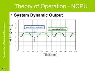
• System Dynamic Output

72

(-)
V
O
L
T
S

24

Vibration Amplitude

20

Average Gap Voltage

16
12
8
4

0

10

20

30

40

50

60

70

80

TIME (ms)

90

100

110

120
Fundamentals of Predictive Maintenance

Ejercicios de ¿Qué Pasa Si? y de Diagnóstico y Solución de Problemas

73

• There are five measurable
characteristics of vibration.
– Frequency
– Displacement (or amplitude)
– Velocity
– Acceleration
– Phase
VIBRATION AMPLITUDE
OVER TIME

74

Amplitude

Fundamentals of Predictive Maintenance

Ejercicios de ¿Qué Pasa Si? y de Diagnóstico y Solución de Problemas

Time
Peak to Peak Displacement
VIBRATION VELOCITY

Ejercicios de ¿Qué Pasa Si? y de Diagnóstico y Solución de Problemas

75

Peak velocity/Zero acceleration
Amplitude

Fundamentals of Predictive Maintenance

Zero velocity/Peak acceleration

Time

Zero velocity/Peak acceleration
Period (Time)
VIBRATION FREQUENCY
Ejercicios de ¿Qué Pasa Si? y de Diagnóstico y Solución de Problemas

76

Amplitude

Fundamentals of Predictive Maintenance

Frequency = 1 / Period

Time

Period (Time)

Example:
If it takes .1 seconds for one cycle (the Period), then
Frequency = 1 / .1 or 10 Cycles Per Second (Hertz)
VIBRATION SIGNAL
DETECTION

77

Amplitude

Fundamentals of Predictive Maintenance

Ejercicios de ¿Qué Pasa Si? y de Diagnóstico y Solución de Problemas

Peak

RMS

Peak to Peak
Time
For Sinusoidal Motion….

78

Peak to Peak = 2 x Peak
RMS = .707 x Peak

Amplitude

Fundamentals of Predictive Maintenance

Ejercicios de ¿Qué Pasa Si? y de Diagnóstico y Solución de Problemas

RMS

Peak to Peak

Peak

Time
Common Vibration Amplitude
Units
Ejercicios de ¿Qué Pasa Si? y de Diagnóstico y Solución de Problemas

Fundamentals of Predictive Maintenance

ENGLISH UNITS
• Displacement
– Mils (0.001 inch)
Peak-to-Peak

• Velocity
– Inches/sec Peak
– Inches/sec RMS

• Acceleration
– G Peak

79

METRIC UNITS
• Displacement

– µm (0.001 millimeter)
Peak-to-Peak

• Velocity
– mm/sec Peak
– mm/sec RMS

• Acceleration
– Meters/Sec2 Peak
RELATIVE PHASE
Fundamentals of Predictive Maintenance

Ejercicios de ¿Qué Pasa Si? y de Diagnóstico y Solución de Problemas

80

• Comparative phase readings show “how” the
machine is vibrating
• Note how relative phase causes significant
changes in vibration seen at the coupling with
little to no change in the amplitudes measured
at points 1 and 2
Frequency Characteristics
Fundamentals of Predictive Maintenance

Ejercicios de ¿Qué Pasa Si? y de Diagnóstico y Solución de Problemas

81

•
•
•
•

Synchronous Vibration
Asynchronous Vibration
Natural Frequency
Resonance
Resonance

Ejercicios de ¿Qué Pasa Si? y de Diagnóstico y Solución de Problemas

Fundamentals of Predictive Maintenance

• Spring System – Pillow Block

82

Shaft coupling
Pillow block
housing

Ball bearing

Flex

• Spring System – Machine Base
Machine Base

Flex

V-belt
pulley
Critical Speed
Fundamentals of Predictive Maintenance

Ejercicios de ¿Qué Pasa Si? y de Diagnóstico y Solución de Problemas

83

• Critical Speed is defined as being a type
of resonance which occurs when a shaft
or rotating machine component revolves
at a speed close to its natural
frequency .
Vibration Indicators
Fundamentals of Predictive Maintenance

Ejercicios de ¿Qué Pasa Si? y de Diagnóstico y Solución de Problemas

84
Vibration Indicators
Fundamentals of Predictive Maintenance

Ejercicios de ¿Qué Pasa Si? y de Diagnóstico y Solución de Problemas

85
Summary (Amplitude,
Frequency, Phase)

Ejercicios de ¿Qué Pasa Si? y de Diagnóstico y Solución de Problemas

Fundamentals of Predictive Maintenance

• Amplitude is the amount of vibration

86

– Measured in units of Acceleration, Velocity,
or Displacement
– Signal Detection is Peak to Peak, Peak, or
RMS

• Frequency is the number of cycles per
second (Hertz) or cycles per minute
(CPM) that a part is vibrating
• Phase is used to determine how one
part is vibrating relative to another part.
Overall Velocity Guidelines
Fundamentals of Predictive Maintenance

Ejercicios de ¿Qué Pasa Si? y de Diagnóstico y Solución de Problemas

87
Overall Alarm Chart

Ejercicios de ¿Qué Pasa Si? y de Diagnóstico y Solución de Problemas

MACHINE TYPE
Cooling Tower Drives

GOOD

FAIR

ALARM

0 - .375
0 - .275
0 - .200

.375 - .600
.275 - .425
.200 - .300

.600
.425
.300

0 - .325
0 - .275
0 - .200
0 - .200
0 - .150

.325 - .500
.275 - .425
.200 - .300
.200 - .300
.150 - .250

.500
.425
.300
.300
.250

Lobe-Type Rotary
0 - .300
Belt-Driven Blowers
0 - .275
General Direct Drive Fans (with Coupling)
0 - .250
Primary Air Fans
0 - .250
Large Forced Draft Fans
0 - .200
Large Induced Draft Fans
0 - .175
Shaft-Mounted Integral Fan (Extended Motor Shaft) 0 - .175
Vane-Axial Fans
0 - .150

.300 - .450
.275 - .425
.250 - .375
.250 - .375
.200 - .300
.175 - .275
.175 - .275
.150 - .250

.450
.425
.375
.375
.300
.275
.275
.250

0 - .275
0 - .200

.275 - .425
.200 - .300

.425
.300

0 - .250
0 - .200
0 - .150

.250 - .400
.200 - .300
.150 - .225

.400
.300
.225

0 - .175
0 - .150

.175 - .275
.150 - .225

.275
.225

Vertical Pumps (12' - 20' Height)
0 - .375
Vertical Pumps (8' - 12' Height)
0 - .325
Vertical Pumps (5' - 8' Height)
0 - .250
Vertical Pumps (0' - 5' Height)
0 - .200
General Purpose Horizontal Pump (Direct Coupled) 0 - .200
Boiler Feed Pumps
0 - .200
Hydraulic Pumps
0 - .125

.375 - .600
.325 - .500
.250 - .400
.200 - .300
.200 - .300
.200 - .300
.125 - .200

.600
.500
.400
.300
.300
.300
.200

.100 - .175
.150 - .225
.100 - .175
.075 - .125
.050 - .075

.175
.225
.175
.125
.075

Long Hollow Drive Shaft
Close Coupled Belt Drive
Close Coupled Direct Drive

Fundamentals of Predictive Maintenance

Compressors
Reciprocating
Rotary Screw
Centrifugal with or without External Gearbox
Centrifugal - Integral Gear (Axial Meas.)
Centrifugal - Integral Gear (Radial Meas.)

Blowers (Fans)

Motor/Generator Sets
Belt-Driven
Direct Coupled

Chillers
Reciprocating
Centrifugal (Open-Air) - Motor & Comp. Separate
Centrifugal (Hermetic) - Motor & Impellers Inside

Large Turbine/Generator
3600 RPM Turbine/Generators
1800 RPM Turbine/Generators

Centrifugal Pumps

Machine Tools

88

Motor
Gearbox Input
Gearbox Output
Spindles:
a. Roughing Operations
b. Machine Finishing

0 - .100
0 - .150
0 - .100
0 - .075
0 - .050
Fundamentals of Predictive Maintenance

Ejercicios de ¿Qué Pasa Si? y de Diagnóstico y Solución de Problemas

89

Frequency Analysis
Measuring Vibration Amplitude

Fundamentals of Predictive Maintenance

Ejercicios de ¿Qué Pasa Si? y de Diagnóstico y Solución de Problemas

90

• The three vibration characteristics,
displacement, velocity, and acceleration are
inter-related.
• When displacement and frequency values are
known, velocity (peak) can be calculated.
• To Calculate Velocity (peak):
 V = 52.3 x D x F x 106

• Where:
 V = velocity (peak) in inches/second
 D = displacement (peak-to-peak) in mils
 F = frequency in CPM
Calculate Acceleration
Fundamentals of Predictive Maintenance

Ejercicios de ¿Qué Pasa Si? y de Diagnóstico y Solución de Problemas

91

• When displacement and frequency are
known, acceleration (peak) can be
determined by using the following
calculation:
• To Calculate Acceleration (peak):
g (peak) = 14.2 x D (F/I 000)2 x i0

• Where:
g = acceleration (peak) due to gravity
D = displacement (peak-to-peak) in mils
F = frequency in CPM
Time Waveforms
Fundamentals of Predictive Maintenance

Ejercicios de ¿Qué Pasa Si? y de Diagnóstico y Solución de Problemas

92

Unbalance

Looseness
Output
Shaft

Time

Gearmesh
Conversion to Frequency
Domain
Ejercicios de ¿Qué Pasa Si? y de Diagnóstico y Solución de Problemas

Amplitude

Complex Waveform

Fundamentals of Predictive Maintenance

A

F.F.T.
T

Time

Amplitude
Freq

A

Frequency
Simple Frequency Spectrum
f

93

Time
Time and Frequency
Domain

Ejercicios de ¿Qué Pasa Si? y de Diagnóstico y Solución de Problemas

Fundamentals of Predictive Maintenance

Simple Waveform

94

Complex Waveform

FMAX
Amplitude

9X

1X

3X

5X

Time Domain
Frequency Domain
TMAX
Spectrum Analysis!!!

95

Amplitude

Fundamentals of Predictive Maintenance

Ejercicios de ¿Qué Pasa Si? y de Diagnóstico y Solución de Problemas

a
I
l
m
a
b
n
c
e

r e
B D
p
C
i eFrequency
e c
l
o
n f
a t
i
u
g
n
g

r
G
m
e
e
a
s
h

Frequency
Real Vibration is Complex
Fundamentals of Predictive Maintenance

Ejercicios de ¿Qué Pasa Si? y de Diagnóstico y Solución de Problemas

96
Resulting Spectrum (FFT)
Fundamentals of Predictive Maintenance

Ejercicios de ¿Qué Pasa Si? y de Diagnóstico y Solución de Problemas

97
Fundamentals of Predictive Maintenance

Ejercicios de ¿Qué Pasa Si? y de Diagnóstico y Solución de Problemas

98

Fixed Frequency
vs.
Order Normalization
Fixed Frequency Spectrum
Speed = 500 RPM
Vibration Amplitude

Fundamentals of Predictive Maintenance

Ejercicios de ¿Qué Pasa Si? y de Diagnóstico y Solución de Problemas

0

1000

2000

3000

Frequency (CPM)

99

4000

5000
Fixed Frequency Spectrum
Speed = 1500 RPM
Vibration Amplitude

Fundamentals of Predictive Maintenance

Ejercicios de ¿Qué Pasa Si? y de Diagnóstico y Solución de Problemas

0

1000

2000

3000

Frequency (CPM)

100

4000

5000
Order Normalized Spectrum
Speed = 500 RPM
Vibration Amplitude

Fundamentals of Predictive Maintenance

Ejercicios de ¿Qué Pasa Si? y de Diagnóstico y Solución de Problemas

0

1

2

3

4

5

6

7

Frequency (Orders)

101

8

9 10
Order Normalized Spectrum
Speed = 1500 RPM
Vibration Amplitude

Fundamentals of Predictive Maintenance

Ejercicios de ¿Qué Pasa Si? y de Diagnóstico y Solución de Problemas

0

1

2

3

4

5

6

7

Frequency (Orders)

102

8

9 10
Fundamentals of Predictive Maintenance

Ejercicios de ¿Qué Pasa Si? y de Diagnóstico y Solución de Problemas

103

Spectrum Alarm Bands
Order Normalized Spectrum
Alarm Bands
Ejercicios de ¿Qué Pasa Si? y de Diagnóstico y Solución de Problemas

Vibration Amplitude

Fundamentals of Predictive Maintenance

Speed = 1800 RPM
Band 1 – Unbalance
Band 2 – Looseness
Band 3 – Bearings
Band 4 – Blade Pass

0

1

2

3

4

5

6

7

Frequency (Orders)

104

8

9 10
Order Normalized Spectrum
Alarm Bands
Ejercicios de ¿Qué Pasa Si? y de Diagnóstico y Solución de Problemas

Vibration Amplitude

Fundamentals of Predictive Maintenance

Speed = 1800 RPM
Band 1 – Unbalance
Band 2 – Looseness
Band 3 – Bearings
Band 4 – Blade Pass

Warning
Danger
Blade Pass
0

1

2

3

4

5

6

7

Frequency (Orders)

105

8

9 10
Trending Band Amplitudes
Ejercicios de ¿Qué Pasa Si? y de Diagnóstico y Solución de Problemas

Fundamentals of Predictive Maintenance

Band 1 – Unbalance

Band 2 – Looseness

Band 3 – Bearings

Band 4 – Blade Pass

-5

-4

-3

-2

-1

0

Time (Days)

106

1

2

3

4

5
A Pump Example

Ejercicios de ¿Qué Pasa Si? y de Diagnóstico y Solución de Problemas

Fundamentals of Predictive Maintenance

How many vanes does this one have?

107
Vane Pass

Ejercicios de ¿Qué Pasa Si? y de Diagnóstico y Solución de Problemas

Fundamentals of Predictive Maintenance

vanes

108

volute
1x

0

The pressure output to the
volute will vary as the vanes
pass depending on how exactly
the vanes line up with the
outlet (volute) at any given
moment.
So with any centrifugal pump
there will be a pulsation
(pressure pulse) that occurs at
a frequency equal to the
number of vanes times the
speed of the pump.

5x

Hz

This is called the “Vane Pass”
frequency. It is always equal to the
number of vanes times the speed of
the pump.
the pump.
800

In this case…
In this case…
Vane Pass = 5x
Vane Pass = 5x
A Coupling / Alignment
Example

Ejercicios de ¿Qué Pasa Si? y de Diagnóstico y Solución de Problemas

Fundamentals of Predictive Maintenance

There will be a coupling joining every component on a machine

109

This is called “angular”
misalignment (you don’t
really need to know that though)

coupling
Two Maximum Forces per
Revolution
Ejercicios de ¿Qué Pasa Si? y de Diagnóstico y Solución de Problemas

Fundamentals of Predictive Maintenance

Imagine that you are this bolt…

110

When you were here, you
would feel a maximum
compressive force

And you would feel a maximum
expansion force here

You would
feel no force
when you
were here
Force is applied in two
directions
Fundamentals of Predictive Maintenance

Ejercicios de ¿Qué Pasa Si? y de Diagnóstico y Solución de Problemas

111

If you drew a plot of the force relative to
expansion or compression, vs. time over one
revolution you would see…

1 Rev.

compression
expansion
Two Maximum Forces per
Revolution
If you drew the same plot of force
Ejercicios de ¿Qué Pasa Si? y de Diagnóstico y Solución de Problemas

(any kind) vs. time you would see…
Fundamentals of Predictive Maintenance

1 Rev.

112

max.
min.

max compression
max expansion

1x
2x

0

A maximum force is
observed twice per
revolution, so…
Hz

800
How Would You Orient The
Sensor?
Ejercicios de ¿Qué Pasa Si? y de Diagnóstico y Solución de Problemas

Fundamentals of Predictive Maintenance

If you were going to attach a sensor to
detect this problem, in what direction
(relative to the shaft) would you place it?

113

1x
This type of misalignment would be
felt mostly in the axial direction, but
also somewhat in the radial
direction.

2x

0

Hz

800
Gears

Input =1000 RPM
Output =2000 RPM
Gear mesh=54000 CPM

Drive 54T

Driven 27T

Vibration Amplitude

Fundamentals of Predictive Maintenance

Ejercicios de ¿Qué Pasa Si? y de Diagnóstico y Solución de Problemas

1x
2x

0

114

20

54x

40
60
80
Frequency (Orders)

100
Rolling Element Bearings

115

Estimation Equations
Defect on Outer Race
~.5xN – 1.2
Defect on Inner Race
~.5xN + 1.2
Ball Spin Frequency
~.2xN-1.2/N
Train Frequency ~.5xN-1.2/N

N=8 (Balls)

Estimation Equations
Defect on Outer Race .5x8 – 1.2 = 2.8
Defect on Inner Race .5xN + 1.2 = 5.2
Ball Spin Frequency .2xN-1.2/N = 1.45
Train Frequency .5-1.2/N = .35

Vibration Amplitude

Fundamentals of Predictive Maintenance

Ejercicios de ¿Qué Pasa Si? y de Diagnóstico y Solución de Problemas

FTF
1X
BSF

0

2

BSOR
BSIR

4

6

8

Frequency (Orders)

10
Summary
Fundamentals of Predictive Maintenance

Ejercicios de ¿Qué Pasa Si? y de Diagnóstico y Solución de Problemas

116

• Review Objectives
• Question and Answer Session
Fundamentals of Predictive Maintenance

Performance
Monitoring
Objectives
Fundamentals of Predictive Maintenance

Ejercicios de ¿Qué Pasa Si? y de Diagnóstico y Solución de Problemas

118

• Define monitoring methods
• Measuring electrical performance
• Measuring fluid performance
Monitoring Methods
Fundamentals of Predictive Maintenance

Ejercicios de ¿Qué Pasa Si? y de Diagnóstico y Solución de Problemas

119

•
•
•
•

Measuring Electrical Performance
Measuring Fluid Performance
Measuring Temperature
Measuring RPM
Establishing Standards
Fundamentals of Predictive Maintenance

Ejercicios de ¿Qué Pasa Si? y de Diagnóstico y Solución de Problemas

120

1. Standards which represent absolute
values.
2. Qualitative type of comparative criteria
such as manufacturer’s design limits.
Judging Performance

Ejercicios de ¿Qué Pasa Si? y de Diagnóstico y Solución de Problemas

Fundamentals of Predictive Maintenance

•

121

•
•
•

What seems to be out of its limit or has
changed?
By how much have the limits changed?
Are the changes occurring slowly or
rapidly?
Are there any other changes which
either confirm or contradict the initial
observations?
Measuring Electrical Performance

Fundamentals of Predictive Maintenance

Ejercicios de ¿Qué Pasa Si? y de Diagnóstico y Solución de Problemas

122

• First – follow proper safety rules
• Common Electrical instruments
– Voltmeters
– Ammeters
– Ohmmeters
– Megohmmeters
– wattmeters
Basic Instruments- Multimeters
Ejercicios de ¿Qué Pasa Si? y de Diagnóstico y Solución de Problemas

Fundamentals of Predictive Maintenance

• Combines reading of:

123

– Voltages
– Resistance
– Current

Analog Multimeter

Digital Multimeter
Ohms Law

I=

Fundamentals of Predictive Maintenance

Ejercicios de ¿Qué Pasa Si? y de Diagnóstico y Solución de Problemas

E
R

124

• The amount of current flowing in an
electrical circuit (I - Measured in
amperage) is dependent upon the value of
electrical pressure (E - measured in volts)
and the amount of opposition to the flow of
current (R - measured in ohms).

E
I=
R
Measuring Voltage
Fundamentals of Predictive Maintenance

Ejercicios de ¿Qué Pasa Si? y de Diagnóstico y Solución de Problemas

125

12.000
+
A

V

Battery
A

V
OFF

A

CO M
Voltage Drop Cont’d

Ejercicios de ¿Qué Pasa Si? y de Diagnóstico y Solución de Problemas

Fundamentals of Predictive Maintenance

7.500

Conductor
Resistance

A

V
OFF

11.500
+

A

A

V

Battery
A

V
OFF

A

126

A

V

COM

COM
Measuring Current

Ejercicios de ¿Qué Pasa Si? y de Diagnóstico y Solución de Problemas

Fundamentals of Predictive Maintenance

.5000

Break circuit to connect
meter. Note: meter leads
are moved to different
inputs for current testing.

A

V

A

V
OFF

A

COM

+
Battery
-

127
Measuring Current Cont’d
Fundamentals of Predictive Maintenance

Ejercicios de ¿Qué Pasa Si? y de Diagnóstico y Solución de Problemas

128

Never
clamp
two
wires at
once!
Measuring Resistance
Fundamentals of Predictive Maintenance

Ejercicios de ¿Qué Pasa Si? y de Diagnóstico y Solución de Problemas

129

Verify zero
setting of meter

Reading
Resistance

0000

5000

V

A

V

A

A

V

A

V
OFF

OFF

A
A

COM

COM
Megohmeter
Fundamentals of Predictive Maintenance

Ejercicios de ¿Qué Pasa Si? y de Diagnóstico y Solución de Problemas

130
Measuring Power

Ejercicios de ¿Qué Pasa Si? y de Diagnóstico y Solución de Problemas

131

Current

Ammeter

±

A

±

V

Voltage

LOAD

A
SOURCE

Fundamentals of Predictive Maintenance

Typical single phase wattmeter connection.
Measuring Power Cont’d
Ejercicios de ¿Qué Pasa Si? y de Diagnóstico y Solución de Problemas

132

±

±

A
V

Measuring Power
±

A

±

V

THREE PHASE LOAD

THREE PHASE SOURCE

Fundamentals of Predictive Maintenance

• Typical single phase wattmeter connection
Protective Devices
Fundamentals of Predictive Maintenance

Ejercicios de ¿Qué Pasa Si? y de Diagnóstico y Solución de Problemas

133

• Fuses
• Circuit Breakers
Fuse Function

Fuse melts and opens

Load

Fuse
Source

Fundamentals of Predictive Maintenance

Ejercicios de ¿Qué Pasa Si? y de Diagnóstico y Solución de Problemas

Normal current

Short
BLADE

BODY

ELEMENT

134

High current

FILLER
Circuit Breaker Operation
Ejercicios de ¿Qué Pasa Si? y de Diagnóstico y Solución de Problemas

Fundamentals of Predictive Maintenance

Pivot point

135

Bimetallic strip
Spring

Breaker
“Made”
Current flow

Breaker
“Tripped”

Hold lever

Contacts
closed

Contacts
open
Measuring Fluid Performance

Fundamentals of Predictive Maintenance

Ejercicios de ¿Qué Pasa Si? y de Diagnóstico y Solución de Problemas

136

• Pascal’s Law simply stated
says: “Pressure applied on a
confined fluid is transmitted
undiminished in all
directions, and acts with
equal force on equal areas,
and at right angles to the
surface.”
Pressure
exerted by fluid
equal in all
directions
Pressure and Force
Fundamentals of Predictive Maintenance

Ejercicios de ¿Qué Pasa Si? y de Diagnóstico y Solución de Problemas

• The force contained by an air
cylinder barrel is the
projected area multiplied by
the pressure
Force = Pressure X Area
Area = Pi X Diameter
4

2

D

Where
=
D = the cylinder bore in inches
P = the pressure in pounds per square inch (psi)
Note = area of rod must be subtracted from total area
if calculating area of pressure at rod end.
Boyles Law
Fundamentals of Predictive Maintenance

Ejercicios de ¿Qué Pasa Si? y de Diagnóstico y Solución de Problemas

• “if the temperature of a confined body of gas
is maintained constant, the absolute pressure
is inversely proportional to the volume.”
F1
F2
V1
P1

F3
V2
P2

V3
P3

P1 X V2 = P2 X V3 = P3 X V3 = constant where P = pressure and V= volume

138
Bernoulli’s Principle
Fundamentals of Predictive Maintenance

Ejercicios de ¿Qué Pasa Si? y de Diagnóstico y Solución de Problemas

139

“in a system with a constant flow rate, energy is
transformed from one form to the other each time the
pipe cross-section size changes”

Ignoring friction losses, the
pressure again becomes the
same as at “A” when the flow
velocity becomes the same as
at “A.”

In the small section pipe, velocity is
maximum. More energy is in the form
of motion, so pressure is lower.

PUMP

B

A
PSI

C
PSI

Velocity decreases in the larger
pipe. The kinetic energy loss is
made up by an increase in
pressure.

PSI
Pressure Measurement

Ejercicios de ¿Qué Pasa Si? y de Diagnóstico y Solución de Problemas

Fundamentals of Predictive Maintenance

• Bourdon Style Gage

140

Tube tends to
straighten under
pressure causing
pointer to rotate.

Bourdon
tube

Pressure Inlet
Flow Measurement
Fundamentals of Predictive Maintenance

Ejercicios de ¿Qué Pasa Si? y de Diagnóstico y Solución de Problemas

141

• By determining the rate of flow to what
the recommended flow rate is supposed
to be is essential for determining
pumping capabilities and efficiencies.
Flow Measurement Cont’d
Fundamentals of Predictive Maintenance

Ejercicios de ¿Qué Pasa Si? y de Diagnóstico y Solución de Problemas

142

• Types of flow measurement devices are the
list following are but a few of the most
common types
–
–
–
–
–
–
–
–

Elbow tap switches
Flow switches
Turbine Flow meters
Rotameter Flow meters
Orfice Flow meters
Venturi tube flow measurement
Doppler Flow meters
Volumetric Flow meters
Elbow Taps
Fundamentals of Predictive Maintenance

Ejercicios de ¿Qué Pasa Si? y de Diagnóstico y Solución de Problemas

143

• Elbow Taps: A flow measurement using elbow taps
depends on the detection of the differential pressure
developed by centrifugal force as the direction of fluid
flow is changed in a pipe elbow
Elbow tap

Elbow tap
Flow
Indicator
Flow switches
Fundamentals of Predictive Maintenance

Ejercicios de ¿Qué Pasa Si? y de Diagnóstico y Solución de Problemas

144

• Flow switches are used to determine if
the flow rate is above or below a
certain value. One type of flow switch
is the swinging vane flow switch.
Switch

Swinging
vane
Turbine Flowmeter
Fundamentals of Predictive Maintenance

Ejercicios de ¿Qué Pasa Si? y de Diagnóstico y Solución de Problemas

Magnetic pickup

Flow
direction

Rotor
145
Doppler Flowmeters
Fundamentals of Predictive Maintenance

Ejercicios de ¿Qué Pasa Si? y de Diagnóstico y Solución de Problemas

146

Transmitting
element

Receiving
element

Flow
direction
Summary
Fundamentals of Predictive Maintenance

Ejercicios de ¿Qué Pasa Si? y de Diagnóstico y Solución de Problemas

147

• Review Objectives
• Question and Answer Session
Fundamentals of Predictive Maintenance

Thermographic
Analysis
Objectives
Fundamentals of Predictive Maintenance

Ejercicios de ¿Qué Pasa Si? y de Diagnóstico y Solución de Problemas

149

•Define infrared
•Types of equipment used
•Define thermographic imaging
•Implementing a maintenance program
•List types of faults
Introduction
Fundamentals of Predictive Maintenance

Ejercicios de ¿Qué Pasa Si? y de Diagnóstico y Solución de Problemas

150

• Thermography is a predictive
maintenance technique that can be used
to monitor the condition of plant
machinery, structures, and systems.
• Involves the measurement or mapping
surface temperatures as heat flows to,
from and/or through an object
Infrared Basics
Fundamentals of Predictive Maintenance

Ejercicios de ¿Qué Pasa Si? y de Diagnóstico y Solución de Problemas

151

• Objects with a temperature above absolute
zero emit energy or radiation
• Infrared radiation is one form of this emitted
energy.
• Three sources of energy
– Emitted energy
– Reflected energy
– Transmitted energy

• Only emitted energy is important in a
predictive maintenance program.
Energy Emissions
Fundamentals of Predictive Maintenance

Ejercicios de ¿Qué Pasa Si? y de Diagnóstico y Solución de Problemas

152

•
•
•
•

A = Absorbed energy.
R = Reflected energy.
T = Transmitted energy.
E = Emitted energy.

A
R
T
A+R+T=1
E=A
E+R+T=1
Blackbody Emissions
Fundamentals of Predictive Maintenance

Ejercicios de ¿Qué Pasa Si? y de Diagnóstico y Solución de Problemas

• A perfect emitting body is called a
“Blackbody”

A

E = A = .7
153

R = .3

T=0
Graybody Emission
Fundamentals of Predictive Maintenance

Ejercicios de ¿Qué Pasa Si? y de Diagnóstico y Solución de Problemas

• Bodies that are not blackbodies will emit
some amount of infrared energy.
A

R
E=A=1

154

R=0

T=0
Infrared Thermometers
Fundamentals of Predictive Maintenance

Ejercicios de ¿Qué Pasa Si? y de Diagnóstico y Solución de Problemas

155

249°
Line Scanners
Fundamentals of Predictive Maintenance

Ejercicios de ¿Qué Pasa Si? y de Diagnóstico y Solución de Problemas

156

• This type of infrared instrument provides
a single-dimensional scan or line of
comparative radiation.
Infrared Imaging
Fundamentals of Predictive Maintenance

Ejercicios de ¿Qué Pasa Si? y de Diagnóstico y Solución de Problemas

157
Infrared Theory
Fundamentals of Predictive Maintenance

Ejercicios de ¿Qué Pasa Si? y de Diagnóstico y Solución de Problemas

158
Implementing a Maintenance
Program
Fundamentals of Predictive Maintenance

Ejercicios de ¿Qué Pasa Si? y de Diagnóstico y Solución de Problemas

159

• Gain support from management .
• Practice reading thermographic images
• Meet regularly with managers, line supervisors
and other co-workers
• Integrate with other predictive maintenance
efforts
• Establish written inspection procedures
• Create inspection routes
• Reporting results
Example Inspection Process
Fundamentals of Predictive Maintenance

Ejercicios de ¿Qué Pasa Si? y de Diagnóstico y Solución de Problemas

160
Overheating Belt/Sheave
Fundamentals of Predictive Maintenance

Ejercicios de ¿Qué Pasa Si? y de Diagnóstico y Solución de Problemas

161
Overheating Belt Drive
Fundamentals of Predictive Maintenance

Ejercicios de ¿Qué Pasa Si? y de Diagnóstico y Solución de Problemas

162
Fundamentals of Predictive Maintenance

Ejercicios de ¿Qué Pasa Si? y de Diagnóstico y Solución de Problemas

163

• Thermal image reveals overheating
bearing on a primary motor
Fundamentals of Predictive Maintenance

Ejercicios de ¿Qué Pasa Si? y de Diagnóstico y Solución de Problemas

164

This panel circuit breaker is hot! Is it a problem?
Without a load reading, diagnosis is difficult. This
may be the only energized breaker in the entire
panel!
Roller, chain and belt
conveyors
Fundamentals of Predictive Maintenance

Ejercicios de ¿Qué Pasa Si? y de Diagnóstico y Solución de Problemas

165

• Thermal imaging is especially useful
for monitoring low-speed mechanical
equipment like conveyors.

These hot spots most likely indicate poor bearing lubrication or component
wear problems.
Inspect Bearings
Fundamentals of Predictive Maintenance

Ejercicios de ¿Qué Pasa Si? y de Diagnóstico y Solución de Problemas

166

• When a motor bearing fails, the motor heats up and
lubrication begins to break down. The windings
overheat and then the temperature sensor cuts out
and stops the motor. Worst case, the shaft binds up,
the rotor locks up and the motor fails completely

overheating shaft and bearing may be an indicator of
bearing failure, lack of proper lubrication, or
misalignment.
Printed Circuit Boards
Fundamentals of Predictive Maintenance

Ejercicios de ¿Qué Pasa Si? y de Diagnóstico y Solución de Problemas

167

Thermal imagers capture two-dimensional
representations of the surface temperatures of
electronics, electrical components and other objects.
Since over- heating may signal that a trace, a solder
joint, or a component (chip, capacitor, resistor, etc.) is
malfunctioning,
Building Inspection
Fundamentals of Predictive Maintenance

Ejercicios de ¿Qué Pasa Si? y de Diagnóstico y Solución de Problemas

168

• Thermal imaging or
thermography can
capture two-dimensional
representations of the
surface temperatures of
parts of buildings,
including roofs, walls,
doors, windows and
construction joints.
Petroleum and petrochemical
processing
Fundamentals of Predictive Maintenance

Ejercicios de ¿Qué Pasa Si? y de Diagnóstico y Solución de Problemas

169

This nitrogen pump had a persistently leaky seal and had to
be changed out regularly. Thermal imaging revealed a
restriction preventing the seal from receiving enough cool
airflow. As a result, the seal was overheating and melting.
Substations and Switchgear

Fundamentals of Predictive Maintenance

Ejercicios de ¿Qué Pasa Si? y de Diagnóstico y Solución de Problemas

170

• Since overheating as well as abnormally cool
operating temperatures may signal the degradation
of an electrical component, thermal imagers provide
the predictive capabilities required for substation
and switchgear maintenance.

For equipment that always has a high operating
temperature, establish a baseline or standard
acceptable temperature range to compare readings to.
Monitoring transformers
Fundamentals of Predictive Maintenance

Ejercicios de ¿Qué Pasa Si? y de Diagnóstico y Solución de Problemas

171

• Most transformers are cooled by either oil or
air while operating at temperatures much
higher than ambient

At 94 ºF, one of the terminals on this 1320V–
480 V main transformer is running about 20 ºF
hotter than it should.
Industrial gearboxes
Fundamentals of Predictive Maintenance

Ejercicios de ¿Qué Pasa Si? y de Diagnóstico y Solución de Problemas

172

The gearbox on this conveyor belt motor assembly
is abnormally warm. The clue is the white-hot shaft
at the center.
Reports

Fundamentals of Predictive Maintenance

Ejercicios de ¿Qué Pasa Si? y de Diagnóstico y Solución de Problemas

173

• When an image reveals
a situation that may
require repairs, a report
should be created
describing what the
image shows and
possibly suggesting a
remedy. The report can
then be circulated to
personnel responsible
for equipment reliability,
who can investigate the
problem further.
Wind Flow
Fundamentals of Predictive Maintenance

Ejercicios de ¿Qué Pasa Si? y de Diagnóstico y Solución de Problemas

174

Wind will affect your temperature readings due to
convection cooling. This can be compensated in
outdoor predictive maintenance applications by
multiplying your temp. reading by the correction factors
listed below.
Wind Speed (Miles Per Hour)

Correction Factor

2
4
6
8
10
12
14
16
18

1.00
1.30
1.60
1.68
1.96
2.10
2.25
2.42
2.60
Summary
Fundamentals of Predictive Maintenance

Ejercicios de ¿Qué Pasa Si? y de Diagnóstico y Solución de Problemas

175

• Review Objectives
• Question and Answer Session
Fundamentals of Predictive Maintenance

Lubrication
Course Objectives
Fundamentals of Predictive Maintenance

Ejercicios de ¿Qué Pasa Si? y de Diagnóstico y Solución de Problemas

177

• Define types of lubrication
• Distinguish the difference between
grease and oil
• Discuss the hazards of mixing different
lubrications
• Describe the proper handling of
lubrication
Introduction to Lubrication
Ejercicios de ¿Qué Pasa Si? y de Diagnóstico y Solución de Problemas

Fundamentals of Predictive Maintenance

• Why use lubricants?

178

– Reduce Friction
– Increase Cooling
Lubrication Functions
Fundamentals of Predictive Maintenance

Ejercicios de ¿Qué Pasa Si? y de Diagnóstico y Solución de Problemas

179

• Form a lubricant film between
components.
• Reduce the effect of friction
• Protect against corrosion
• Seal against contaminants
• Cool moving parts
Lubrication
Fundamentals of Predictive Maintenance

Ejercicios de ¿Qué Pasa Si? y de Diagnóstico y Solución de Problemas

180
Friction

Fundamentals of Predictive Maintenance

Ejercicios de ¿Qué Pasa Si? y de Diagnóstico y Solución de Problemas

181

• Grease and oil lubricate the moving
parts of a machine
• Grease and oil reduce friction, heat, and
wear of moving machine parts
Oil = Low Friction and Heat
Fundamentals of Predictive Maintenance

Ejercicios de ¿Qué Pasa Si? y de Diagnóstico y Solución de Problemas

182
No Oil = High Friction and Heat
Fundamentals of Predictive Maintenance

Ejercicios de ¿Qué Pasa Si? y de Diagnóstico y Solución de Problemas

183
Ejercicios de ¿Qué Pasa Si? y de Diagnóstico y Solución de Problemas

Fundamentals of Predictive Maintenance

Bearing
center

184

Shaft
center

Loaded
area

Oil delivery
Lubrication Prevents Failure of:
Fundamentals of Predictive Maintenance

Ejercicios de ¿Qué Pasa Si? y de Diagnóstico y Solución de Problemas

185

•
•
•
•

Bearings
Gears
Couplings
Chains
Lubrication Prevents Failure of:
Fundamentals of Predictive Maintenance

Ejercicios de ¿Qué Pasa Si? y de Diagnóstico y Solución de Problemas

186

•
•
•
•

Engine components
Hydraulic pumps
Gas and Steam Turbines
Any moving parts
Lubricants prevent failure by:
Fundamentals of Predictive Maintenance

Ejercicios de ¿Qué Pasa Si? y de Diagnóstico y Solución de Problemas

187

•
•
•
•

Inhibiting rust and corrosion
Absorbing contaminates
Displacing moisture
Flushing away particles
Lubricant Selection
Fundamentals of Predictive Maintenance

Ejercicios de ¿Qué Pasa Si? y de Diagnóstico y Solución de Problemas

188

•
•
•
•
•
•

Operating temperature
Load
Speed
Environment
Grease Lubrication
Oil Lubrication
Grease

Fundamentals of Predictive Maintenance

Ejercicios de ¿Qué Pasa Si? y de Diagnóstico y Solución de Problemas

189

• Grease is a heavy, non-liquid
lubricant
• Grease can have a mineral, lithium
or soap base
• Grease is pasty, thick and sticky
Grease

Fundamentals of Predictive Maintenance

Ejercicios de ¿Qué Pasa Si? y de Diagnóstico y Solución de Problemas

190

• Some greases remain a paste from
below 0°C to above 200°C.
• The flashpoint of most greases is
above 200°C
• Grease does not become a mist under
pressure
Oil

Fundamentals of Predictive Maintenance

Ejercicios de ¿Qué Pasa Si? y de Diagnóstico y Solución de Problemas

191

• Oil can be a heavy or thin liquid
lubricant
• Oil can have a natural base
(mineral)
• Oil can have a synthetic base
(engineered)
Oil

Fundamentals of Predictive Maintenance

Ejercicios de ¿Qué Pasa Si? y de Diagnóstico y Solución de Problemas

192

• Oil remains liquid from below 0°C to
above 200°C.
• The flashpoint of many oils is above
200°C
• The flashpoint is very low for
pressurized oil mist. Why?
How are grease and oil different?
Ejercicios de ¿Qué Pasa Si? y de Diagnóstico y Solución de Problemas

Fundamentals of Predictive Maintenance

• How oil is used:

193

– Oil used in closed systems with pumps.
An oil sump on a diesel engine pumps
liquid oil.
– Oil is used in gas and steam turbines
– Oil is used in most machines that need
liquid lubricant
How grease is used?
Fundamentals of Predictive Maintenance

Ejercicios de ¿Qué Pasa Si? y de Diagnóstico y Solución de Problemas

194

– In areas where a continuous supply of oil
cannot be retained, (open bearings, gears
chains, hinged joints)
– Factors to be considered when selecting
greases are:
• Type. Depends on operating
temperatures, water resistance, oxidation
stability etc
• Characteristics. Viscosity and
consistency
Grease or Oil?
Fundamentals of Predictive Maintenance

Ejercicios de ¿Qué Pasa Si? y de Diagnóstico y Solución de Problemas

195

• What determines whether a machine
needs grease or oil?
• The manufacturer specifies what
lubricant is used in their machines,
based on the properties of the lubricant.
One important property is VISCOSITY.
Viscosity

Fundamentals of Predictive Maintenance

Ejercicios de ¿Qué Pasa Si? y de Diagnóstico y Solución de Problemas

196

• Liquid oil has lower viscosity than grease
paste
• Grease paste has higher viscosity than
liquid oil
What is Viscosity?
Fundamentals of Predictive Maintenance

Ejercicios de ¿Qué Pasa Si? y de Diagnóstico y Solución de Problemas

197
Viscosity

Fundamentals of Predictive Maintenance

Ejercicios de ¿Qué Pasa Si? y de Diagnóstico y Solución de Problemas

198

•
•
•
•

Viscosity is a liquid’s resistance to flow
Viscosity affects the thickness of a liquid
High viscosity liquids are hard to pour
Low viscosity liquids are easy to pour
Viscosity Rules of Thumb
Fundamentals of Predictive Maintenance

Ejercicios de ¿Qué Pasa Si? y de Diagnóstico y Solución de Problemas

199

• the lower the temperature, the lighter the
oil
• the higher the temperature, the heavier
the oil
• the heavier the load, the heavier the oil
• the lighter the load, the lighter the oil
• the faster the speed, the lighter the oil
• the slower the speed, the heavier the oil
Viscosity

Fundamentals of Predictive Maintenance

Ejercicios de ¿Qué Pasa Si? y de Diagnóstico y Solución de Problemas

200

Low
Viscosity

High
Viscosity
Viscosity

Fundamentals of Predictive Maintenance

Ejercicios de ¿Qué Pasa Si? y de Diagnóstico y Solución de Problemas

201

Temperature affects viscosity.
• Heat decreases viscosity
• Cold increases viscosity
• Viscosity is measured in centistokes
(cSt)
Consistency
Fundamentals of Predictive Maintenance

Ejercicios de ¿Qué Pasa Si? y de Diagnóstico y Solución de Problemas

202

•
•
•
•
•
•

Fundamental principle
Thickener
Operating temperature
Mechanical conditions
Low temperature effect
High temperature effect
Additives

Fundamentals of Predictive Maintenance

Ejercicios de ¿Qué Pasa Si? y de Diagnóstico y Solución de Problemas

203

• Antifoaming
• Demulsibility – prevention of emulsions.
• Detergents
Grease Lubrication
Fundamentals of Predictive Maintenance

Ejercicios de ¿Qué Pasa Si? y de Diagnóstico y Solución de Problemas

204

•
•
•
•

How grease works
Thickening agent
Properties
Where used
Advantages of Grease Lubrication

Fundamentals of Predictive Maintenance

Ejercicios de ¿Qué Pasa Si? y de Diagnóstico y Solución de Problemas

205

•
•
•
•

Reduction of dripping and splattering
Hard to get points
Reduction of frequency of lubrication
Helps seal out contaminants and
corrosives.
• Ability to cling to part
• Used to suspend other solids
Grease Selection Factors
Fundamentals of Predictive Maintenance

Ejercicios de ¿Qué Pasa Si? y de Diagnóstico y Solución de Problemas

206

– Load condition
– Speed range
– Operating conditions
– Temperature conditions
– Sealing efficiency
– External environment
Oil Types

Fundamentals of Predictive Maintenance

Ejercicios de ¿Qué Pasa Si? y de Diagnóstico y Solución de Problemas

207

• Two types of lubrication oil are:
• Mineral-based
• Synthetic
Mineral-Based Oil
Fundamentals of Predictive Maintenance

Ejercicios de ¿Qué Pasa Si? y de Diagnóstico y Solución de Problemas

208

• Mineral-based oil is refined from crude
oil hydrocarbons
• Mineral-based oil has 2 types of base:
– Naphtha Base
• A naphtha base is solvent-like

– Paraffin Base
• A paraffin base is waxy
Mineral-Based Oil

Ejercicios de ¿Qué Pasa Si? y de Diagnóstico y Solución de Problemas

Fundamentals of Predictive Maintenance

• Naphtha Base

209

– Lower viscosity index (40-80 cs)
– Lower pour point
– Less resistant to oxidation and changes
in viscosity index
– Good performance at higher
temperatures
Mineral-Based Oil

Ejercicios de ¿Qué Pasa Si? y de Diagnóstico y Solución de Problemas

Fundamentals of Predictive Maintenance

• Paraffinic Base

210

– Higher viscosity index (>95cs)
– Higher pour point
– Very resistant to changes in viscosity
index and oxidation
– Thicken at low temperatures
Mineral-Based Oil
Fundamentals of Predictive Maintenance

Ejercicios de ¿Qué Pasa Si? y de Diagnóstico y Solución de Problemas

211

• Mineral-based oils are cheaper to buy
than synthetics.
• Mineral-based oils can contain traces
of sulfur and nitrogen. These
impurities can cause oil to form
sludge.
Synthetic Oil
Fundamentals of Predictive Maintenance

Ejercicios de ¿Qué Pasa Si? y de Diagnóstico y Solución de Problemas

212

• Synthetic oil is NOT refined from crude
oil hydrocarbons
• Synthetic oil is made without a mineral
base
• Synthetic oil is made by careful control
of a chemical reaction that yields a
“pure” substance
Synthetic Oil
Fundamentals of Predictive Maintenance

Ejercicios de ¿Qué Pasa Si? y de Diagnóstico y Solución de Problemas

213

• Synthetic oils are chemically
engineered to be pure. They do not
contain the traces of sulfur or nitrogen
present in mineral-based oils.
• Synthetic oils are expensive
Synthetic Oil
Fundamentals of Predictive Maintenance

Ejercicios de ¿Qué Pasa Si? y de Diagnóstico y Solución de Problemas

214

• Synthetic oil is less flammable than
mineral-based oil at low pressure.
(Pressure causes most oils to become
more flammable)
• Synthetic oils are generally more
expensive than mineral based oils
Lubricant Specifications
Fundamentals of Predictive Maintenance

Ejercicios de ¿Qué Pasa Si? y de Diagnóstico y Solución de Problemas

215

• ISO = International Standards
Organization
• SAE = Society of Automotive
Engineers
ISO Lubricant Specifications
Fundamentals of Predictive Maintenance

Ejercicios de ¿Qué Pasa Si? y de Diagnóstico y Solución de Problemas

216

• ISO Grade lubricants are for industrial
use. ISO specifications exist for
lubricants in extreme industrial
environments.
ISO Lubricants

Ejercicios de ¿Qué Pasa Si? y de Diagnóstico y Solución de Problemas

Fundamentals of Predictive Maintenance

ISO GRADE

217

Viscosity
40°C
100°C

32

46

68

100

30.4
5.2

43.7
6.6

64.6
8.5

30.4
5.2

222(432)

224(435)

245(473)

262(504)

-36(-33)

-36(-33)

-33(-27)

-30(-22)

Flash Point

°C(°F)

Pour Point
°C(°F)
Using Different Lubricants
Fundamentals of Predictive Maintenance

Ejercicios de ¿Qué Pasa Si? y de Diagnóstico y Solución de Problemas

218

• Why do we use different lubricants?
• What happens if oils are mixed?
Mixing Lubricants
Fundamentals of Predictive Maintenance

Ejercicios de ¿Qué Pasa Si? y de Diagnóstico y Solución de Problemas

219

• Consequences of mixing different
lubricants are:
• Change of viscosity
• Stripping of machine’s internal
coatings, damage to seals
• Reduced flash point, risk of fire
Mixing Lubricants
Fundamentals of Predictive Maintenance

Ejercicios de ¿Qué Pasa Si? y de Diagnóstico y Solución de Problemas

220

•
•
•
•

Loss of corrosion protection
Poor water separation
Foaming
Thermal instability
Fundamentals of Lubrication
Ejercicios de ¿Qué Pasa Si? y de Diagnóstico y Solución de Problemas

Fundamentals of Predictive Maintenance

• Equipment lubrication

221

– Bearings
– Gears
– Couplings
– Chains
Lubricant Delivery Methods
Fundamentals of Predictive Maintenance

Ejercicios de ¿Qué Pasa Si? y de Diagnóstico y Solución de Problemas

222

•
•
•
•
•
•

Force Feed Lubricant
Oil Mist
Constant Circulation
Oil Slinger
Zerk Fittings
Surface Application (brush or spray)
Force Feed Lubrication
Fundamentals of Predictive Maintenance

Ejercicios de ¿Qué Pasa Si? y de Diagnóstico y Solución de Problemas

223

• A force feed lubricant system is like an
automated version of the hand held oil
can. An automatic plunger applies
pressure to deliver a few drops at
predetermined time intervals.
Oil Applicators
Fundamentals of Predictive Maintenance

Ejercicios de ¿Qué Pasa Si? y de Diagnóstico y Solución de Problemas

224
Grease Lubrication
Fundamentals of Predictive Maintenance

Ejercicios de ¿Qué Pasa Si? y de Diagnóstico y Solución de Problemas

225
Lubrication Check Example

Fundamentals of Predictive Maintenance

Ejercicios de ¿Qué Pasa Si? y de Diagnóstico y Solución de Problemas

226

Hand
grease
square slide
shaft and
worm shaft
(Monthly)
1 to 2
pumps per
shaft of
(Mobil
XHP222)

Grease
support
wheel
bearings
(Quarterly)
1 to 2
pumps with
(Mobil
XHP222)

Grease Variable Pitch Pulley
(Quarterly) 1 to 2 Pumps of
(Mobil XHP222)

Hand Oil Roller Chain,
[behind guard] (Quarterly)
(LPS) (24810)

Check
Windup
Gear Boxes
(Quarterly)
Oil type
ISO360
(Mobil Gear
636)
Zerk Fittings
Fundamentals of Predictive Maintenance

Ejercicios de ¿Qué Pasa Si? y de Diagnóstico y Solución de Problemas

227

• Zerk Fittings are grease fill points
that have an internal check valve that
prevents contaminates from entering
the fitting. Always clean the Zerk
fitting before applying grease.
Lubrication Practices
Fundamentals of Predictive Maintenance

Ejercicios de ¿Qué Pasa Si? y de Diagnóstico y Solución de Problemas

228

•
•
•
•
•

Using grease gun
Oil samples
Removing contamination
Leaks
Follow lubrication instructions
Summary

Fundamentals of Predictive Maintenance

Ejercicios de ¿Qué Pasa Si? y de Diagnóstico y Solución de Problemas

229

• Review Objectives
• Question and Answer Session
Fundamentals of Predictive Maintenance

Tribology
(Oil Analysis)
Course Objectives
Fundamentals of Predictive Maintenance

Ejercicios de ¿Qué Pasa Si? y de Diagnóstico y Solución de Problemas

231

• Define Tribology
• Oil Analysis Tests
• Discuss the hazards of mixing different
lubrications
• Describe the proper handling of
lubrication
Introduction to Tribology
Fundamentals of Predictive Maintenance

Ejercicios de ¿Qué Pasa Si? y de Diagnóstico y Solución de Problemas

232

• Tribology is the general term that refers
to oil analysis, spectrographic analysis,
ferrography, and wear particle analysis.
Lubricating Oil Analysis Tests

Fundamentals of Predictive Maintenance

Ejercicios de ¿Qué Pasa Si? y de Diagnóstico y Solución de Problemas

233

•
•
•
•
•
•
•
•
•
•
•

Viscosity
Contamination
Fuel Dilution
Solids Content
Fuel Soot
Oxidation
Nitration
Total Acid Number (TAN)
Total Base Number (TBN)
Particle Count
Spectrographic Analysis
TAN

Fundamentals of Predictive Maintenance

Ejercicios de ¿Qué Pasa Si? y de Diagnóstico y Solución de Problemas

234

• Measures of the acid concentration of the oil
• As oil ages and oxidizes small amounts of
acid are formed
• Indication of the amount of degradation of oil
• TAN above 4.0 is highly corrosive, attacking
bearings and other metals
TBN

Fundamentals of Predictive Maintenance

Ejercicios de ¿Qué Pasa Si? y de Diagnóstico y Solución de Problemas

235

• Measures of the alkalinity the oil
• Engine oil has additives to neutralize
acids generated during combustion
• Indication of the amount of degradation
of oil
• Once depleted the oil can become
highly corrosive, attacking bearings and
other metals
Wear Particle Analysis
Fundamentals of Predictive Maintenance

Ejercicios de ¿Qué Pasa Si? y de Diagnóstico y Solución de Problemas

236

• Provides information about the wearing
condition of the machine.
• Particles in lubricant are studied for
– Shape
– Composition
– Size
– Quantity
Types of Wear
Fundamentals of Predictive Maintenance

Ejercicios de ¿Qué Pasa Si? y de Diagnóstico y Solución de Problemas

237

• Five basic types of wear can be identified
according to the classification of particle
– Rubbing wear
– Cutting wear particles
– Rolling fatigue
– Combined Rolling and Sliding wear
– Severe Sliding Wear
Ferrography
Fundamentals of Predictive Maintenance

Ejercicios de ¿Qué Pasa Si? y de Diagnóstico y Solución de Problemas

238

• Similar to spectrography except a
magnetic field is used to separate
particles.
• Particles larger than 10 microns can be
separated.
• Analytical Ferrography utilizes
microscopic analysis to identify the
composition of material present.
Example Slide

Ejercicios de ¿Qué Pasa Si? y de Diagnóstico y Solución de Problemas

Fundamentals of Predictive Maintenance

Magnetic Flux Lines

239

Non-Magnetic Particles
Wetting Barrier

Strong Magnet
Ferrogram photos
Fundamentals of Predictive Maintenance

Ejercicios de ¿Qué Pasa Si? y de Diagnóstico y Solución de Problemas

240

• Photographs of ferrograms showing
severe sliding wear during break-in
Fundamentals of Predictive Maintenance

Ejercicios de ¿Qué Pasa Si? y de Diagnóstico y Solución de Problemas

241

• Ferrograms of fine rubbing wear and
the occasional larger particle
Spectroscopy
Fundamentals of Predictive Maintenance

Ejercicios de ¿Qué Pasa Si? y de Diagnóstico y Solución de Problemas

242

• Uses an IR radiation source
• Radiation is passed through the sample
to a detector.
Example FTIR Spectroscopy
Ejercicios de ¿Qué Pasa Si? y de Diagnóstico y Solución de Problemas

Glycol
Fundamentals of Predictive Maintenance

Sulfation
Antioxidant
Water

Oxidation

Fuel

Soot

3900

243

AW

Nitration

3500

3100

2700

2300
1900
Wavenumber

1500

1100

700
Typical Results of Testing
Fundamentals of Predictive Maintenance

Ejercicios de ¿Qué Pasa Si? y de Diagnóstico y Solución de Problemas

244
Typical Results of Testing
Fundamentals of Predictive Maintenance

Ejercicios de ¿Qué Pasa Si? y de Diagnóstico y Solución de Problemas

245
Typical Results of Testing
Fundamentals of Predictive Maintenance

Ejercicios de ¿Qué Pasa Si? y de Diagnóstico y Solución de Problemas

246
Analysis Progams
Fundamentals of Predictive Maintenance

Ejercicios de ¿Qué Pasa Si? y de Diagnóstico y Solución de Problemas

247

• Lubricant analysis programs are tests used to
determine whether a lubricant remains
effective.
• A lubricant analysis program may allow longer
intervals between changing lubricants.
• In this program, samples of lubricant are
collected and either analyzed in the field
(using test equipment) or sent to an analytical
laboratory for analysis.
• Representative sample collection is critical to
ensure that the sample being analyzed is
indicative of the lubricant's overall condition.
Benefits

Fundamentals of Predictive Maintenance

Ejercicios de ¿Qué Pasa Si? y de Diagnóstico y Solución de Problemas

248

• Reduces the frequency of oil changes.
• Decreases consumption and purchase
of virgin oil.
• Reduces the generation of waste oil.
• Provides valuable diagnostic
information.
Disadvantages
Fundamentals of Predictive Maintenance

Ejercicios de ¿Qué Pasa Si? y de Diagnóstico y Solución de Problemas

249

• Higher level of knowledge is required to
perform the diagnostic tests or take
representative samples.
• Data must be collected over time and
analyzed to determine trends.
• Results are subject to interpretation.
• Oil analyzers must be calibrated to the
type and manufacturer of the oil being
used.
Equipment Audit
Fundamentals of Predictive Maintenance

Ejercicios de ¿Qué Pasa Si? y de Diagnóstico y Solución de Problemas

250

• An equipment audit should be performed
to obtain:
–
–
–
–
–

knowledge of the equipment
its internal design
the system design
present operating
environmental conditions
Lubricant Audit
Fundamentals of Predictive Maintenance

Ejercicios de ¿Qué Pasa Si? y de Diagnóstico y Solución de Problemas

251

• Equipment reliability requires a lubricant that
meets and maintains specific physical,
chemical, and cleanliness requirements.
• A detailed trail of a lubricant is required,
beginning with the oil supplier and ending after
disposal of spent lubricants.
• Sampling and testing of the lubricants are
important to validate the lubricant condition
throughout its life cycle.
Baseline Signature
Fundamentals of Predictive Maintenance

Ejercicios de ¿Qué Pasa Si? y de Diagnóstico y Solución de Problemas

252

• The baseline signature should be designed to
gather and analyze all data required to
determine the current health of
– the equipment
– lubricant

• The baseline signature or baseline reading
requires a minimum of three consecutive,
timely samples, preferably in a short duration
(i.e., one per month) to effectively evaluate the
present trend in the equipment condition.
Monitoring
Fundamentals of Predictive Maintenance

Ejercicios de ¿Qué Pasa Si? y de Diagnóstico y Solución de Problemas

253

These activities are performed to collect
and trend any early signs of deteriorating
lubricant and equipment condition
•Routing Monitoring
•Routes
•Frequency of Monitoring
•Tests
Analysis

Fundamentals of Predictive Maintenance

Ejercicios de ¿Qué Pasa Si? y de Diagnóstico y Solución de Problemas

254

• Data Analysis
• Root Cause Analysis
Reports

Fundamentals of Predictive Maintenance

Ejercicios de ¿Qué Pasa Si? y de Diagnóstico y Solución de Problemas

255

– Specific equipment identification
– Data of sample
– Date of report
– Present condition of equipment and
lubricant
– Recommendations
– Sample test result data
– Analyst’s name
Summary

Fundamentals of Predictive Maintenance

Ejercicios de ¿Qué Pasa Si? y de Diagnóstico y Solución de Problemas

256

• Review Objectives
• Question and Answer Session
Fundamentals of Predictive Maintenance

Non-Destructive
Testing (NDT)
Objectives
Fundamentals of Predictive Maintenance

Ejercicios de ¿Qué Pasa Si? y de Diagnóstico y Solución de Problemas

258

• Upon completion of this course
students will be able to:
– Define the purpose of non-destructive
testing
– Define visual inspection
– Define liquid penetrant testing
– Define magnetic particle testing
Purpose

Ejercicios de ¿Qué Pasa Si? y de Diagnóstico y Solución de Problemas

Fundamentals of Predictive Maintenance

• To reduce the rate of machine failure by

259

– Checking for defects that may cause a part
to fail
– Verify a part is within specified tolerances
– Conditions will allow machine to operate at
maximum efficiency
Types of Faults
Fundamentals of Predictive Maintenance

Ejercicios de ¿Qué Pasa Si? y de Diagnóstico y Solución de Problemas

260

–
–
–
–
–
–

Cracks
Erosion
Wear
Loss of coating
Reductions in thickness or wall size
Weld integrity

An assembled machine can also be checked
for:
–
–
–
–

Correct assembly
Loose parts
Damage
Blockages
Types

Fundamentals of Predictive Maintenance

Ejercicios de ¿Qué Pasa Si? y de Diagnóstico y Solución de Problemas

261

•
•
•
•
•
•

Visual
Liquid Penetrant
Magnetic Particle
Ultrasonic
Eddy Current
Radiography
Direct Visual Inspection
Fundamentals of Predictive Maintenance

Ejercicios de ¿Qué Pasa Si? y de Diagnóstico y Solución de Problemas

262

• NDE (non-destructive examination)
• Requirements
– Adequate light
– Good eyesight
– Ability to get close to equipment
– Experience/Knowledge
– May need magnification instruments
Remote Visual Inspection
Fundamentals of Predictive Maintenance

Ejercicios de ¿Qué Pasa Si? y de Diagnóstico y Solución de Problemas

263

• RVI allows the detection, observation or
analysis of defects inaccessible to the
eye.
– The simplest tool is a swivel type mirror

• Main tools are
– Videolmagescope
– Fiberscope
– Borescope
Video Image Scope
Fundamentals of Predictive Maintenance

Ejercicios de ¿Qué Pasa Si? y de Diagnóstico y Solución de Problemas

264

• The scope has a camera built into the
end of a flexible probe.
Articulation
Control

Light guide
cable

Interchangeable
tip adapters

Light guide
connector
CCU
connector
Fiberscope
Fundamentals of Predictive Maintenance

Ejercicios de ¿Qué Pasa Si? y de Diagnóstico y Solución de Problemas

265

• Differs from video image scope, the
image is seen at the eyepiece
Image guide
Eyepiece
Light guide
Light
source
Focusing eyepiece
Fiber optic light guide

Objective lens

Object
Illumination area
Borescope
Fundamentals of Predictive Maintenance

Ejercicios de ¿Qué Pasa Si? y de Diagnóstico y Solución de Problemas

• The borescope is another instrument for
remotely inspecting the inside of a
machine by optical means.
Focus control
Eye cup

Light guide
window
Eyepiece

266

Direction indicator
Field of
view
Cap
Liquid Penetrant

Ejercicios de ¿Qué Pasa Si? y de Diagnóstico y Solución de Problemas

Fundamentals of Predictive Maintenance

• A common method of checking for
cracks due to:

267

– Fatigue
– Grinding
– Welding
– Casting
– Shrinkage
– Lack of bonding
– Delamination
– Etc.
Advantages

Ejercicios de ¿Qué Pasa Si? y de Diagnóstico y Solución de Problemas

Fundamentals of Predictive Maintenance

• The advantages of liquid penetrant are:

268

– Can be used on a wide variety of materials.
– Simple to use and does not require
extensive training.
– Does not require expensive and dedicated
equipment.
Disadvantages
Fundamentals of Predictive Maintenance

Ejercicios de ¿Qué Pasa Si? y de Diagnóstico y Solución de Problemas

269

• The disadvantages of liquid penetrant
are:
– Does not detect sub-surface faults.
– Does not indicate the width or depth of a
crack.
– Cannot be used on porous materials or
materials that do not have a smooth
surface.
Five steps of Liquid Penetrant

Fundamentals of Predictive Maintenance

Ejercicios de ¿Qué Pasa Si? y de Diagnóstico y Solución de Problemas

1. Surface
preparation

2. Penetrant
application

4. Developing
270

3. Removal of the
excess penetrant

5. Inspection and
Interpretation
Magnetic Particle Inspection MPI
Fundamentals of Predictive Maintenance

Ejercicios de ¿Qué Pasa Si? y de Diagnóstico y Solución de Problemas

271

• Magnetic particle inspection (MPI) is a
nondestructive testing method used for defect
detection.
• MPI uses magnetic fields and small magnetic
particles (iron filings) to detect flaws in
components.
• The only requirement is that the component
being inspected must be made of a
ferromagnetic material such as iron, nickel,
cobalt, or some of their alloys
Basic Principle
Fundamentals of Predictive Maintenance

Ejercicios de ¿Qué Pasa Si? y de Diagnóstico y Solución de Problemas

272

Any place that a magnetic line of force exits or enters
the magnet is called a pole. A pole where a magnetic
line of force exits the magnet is called a north pole
and a pole where a line of force enters the magnet is
called a south pole.
Magnetic particles

North pole

Magnetic field lines

S

N

South pole
Magnetic Flux and Leakage
Fundamentals of Predictive Maintenance

Ejercicios de ¿Qué Pasa Si? y de Diagnóstico y Solución de Problemas

Flux lines
A. Uniform Flux Lines
Leakage from
surface flaw
B. Distortion by a surface crack
Leakage from
Subsurface flaw
C. Distortion by Internal Flaw near the Surface

273
Advantages/Disadvantages
Fundamentals of Predictive Maintenance

Ejercicios de ¿Qué Pasa Si? y de Diagnóstico y Solución de Problemas

274

The advantages of the Magnetic Particle method
are:
– sensitive to flaws of almost any size shape and
composition.
– can detect flaws that are just below the surface.

The disadvantages of the Magnetic Particle
method are:
– can only be applied to ferromagnetic material.
– if the magnetic flux is parallel to the crack it will not
show, therefore perhaps requiring two or more tests.
Three Steps of MPI

Ejercicios de ¿Qué Pasa Si? y de Diagnóstico y Solución de Problemas

Fundamentals of Predictive Maintenance

•

275

Magnetization of the part

•

Application of the particles

•

Inspection and interpretation
Magnetization

Ejercicios de ¿Qué Pasa Si? y de Diagnóstico y Solución de Problemas

Fundamentals of Predictive Maintenance

• Four methods

276

– Coil around a piece
– Current through a piece
– Current through a portion
using prods
– Electro-magnetic Yoke.
Application of Particles
Fundamentals of Predictive Maintenance

Ejercicios de ¿Qué Pasa Si? y de Diagnóstico y Solución de Problemas

277

• The particles consist of a fine iron oxide
powder that are elongated to assist in
polarization and lubricated to enhance
their mobility.
• Two types of particles
– Dry (usually dyed)
– Wet (usually treated with fluorescent
material)
MPI Inspection/Interpretation

Fundamentals of Predictive Maintenance

Ejercicios de ¿Qué Pasa Si? y de Diagnóstico y Solución de Problemas

278

• Flaw detection depends on a number of
factors
– Strength of magnetic field
– Orientation of fault to flux lines
– Depth of the flaw
– Strength of current used
– Location of prods, yoke or coil
Eddy Current Testing - ET
Fundamentals of Predictive Maintenance

Ejercicios de ¿Qué Pasa Si? y de Diagnóstico y Solución de Problemas

279

• Used to inspect electrically conducting
specimens for defects, irregularities in
structure, and determining coating
thickness
Eddy Current Principle

Ejercicios de ¿Qué Pasa Si? y de Diagnóstico y Solución de Problemas

Fundamentals of Predictive Maintenance

Alternating current

280

Probe
Magnetic field

Eddy
Currents
or
secondary
magnetic
field

Fault
Advantages
Fundamentals of Predictive Maintenance

Ejercicios de ¿Qué Pasa Si? y de Diagnóstico y Solución de Problemas

281

•
•
•
•
•
•
•
•

Crack detection
Material thickness measurements
Coating thickness measurements
Conductivity measurements for:
Material identification
Heat damage detection
Case depth determination
Heat treatment monitoring
Disadvantages
Fundamentals of Predictive Maintenance

Ejercicios de ¿Qué Pasa Si? y de Diagnóstico y Solución de Problemas

282

• Only conductive materials can be inspected
• Surface must be accessible to the probe
• Skill and training required is more extensive
than other techniques
• Surface finish and roughness may interfere
• Reference standards needed for setup
• Depth of penetration is limited
• Flaws such as delaminations that lie parallel to
the probe coil winding and probe scan
direction are undetectable
Radiography Testing - RT
Fundamentals of Predictive Maintenance

Ejercicios de ¿Qué Pasa Si? y de Diagnóstico y Solución de Problemas

283

• Widely used processes to detect subsurface defects and faults
• Permanent record is produced in the
form of an image created on a film that
was exposed to a source of radiant
energy
Example Radiography

Ejercicios de ¿Qué Pasa Si? y de Diagnóstico y Solución de Problemas

Fundamentals of Predictive Maintenance

Source

284

Radiation Beam

Weld

Slag

Film
Sources

Fundamentals of Predictive Maintenance

Ejercicios de ¿Qué Pasa Si? y de Diagnóstico y Solución de Problemas

285

• There are two sources of penetrating
waves which are suitable for
radiography:
– X-ray
– Gamma Ray
Advantages of X-Rays
Fundamentals of Predictive Maintenance

Ejercicios de ¿Qué Pasa Si? y de Diagnóstico y Solución de Problemas

286

• No residual radiation is generated or retained
when the power is switched off.
• Penetrating power is adjustable through
varying the high voltage (kV) input.
• Can be used on all materials (including
aluminum).
• Provides radiographs with good contrast and
sensitivity.
• Sufficient size machines exist to radiograph
through 20 inches (500 mm) of steel.
Disadvantages of X-Rays
Fundamentals of Predictive Maintenance

Ejercicios de ¿Qué Pasa Si? y de Diagnóstico y Solución de Problemas

287

• High initial cost.
• Requires source of electrical power.
• Equipment not very portable, also
relatively fragile.
• Tube head usually large in size,
unusable in tight locations.
• Electrical hazard from high voltage.
Advantages of Gamma Rays

Fundamentals of Predictive Maintenance

Ejercicios de ¿Qué Pasa Si? y de Diagnóstico y Solución de Problemas

288

• Small initial and low maintenance costs.
• Rugged construction, more suited to
industrial locations.
• No electric power required or concern of
electrical hazard.
• High penetrating power.
• Portable with access into small areas
with source tube.
Disadvantages of Gamma Rays

Fundamentals of Predictive Maintenance

Ejercicios de ¿Qué Pasa Si? y de Diagnóstico y Solución de Problemas

289

• Radiation hazard and radiation emitted
continuously.
• Penetrating power cannot be adjusted.
• Radioisotope decays in strength requiring
recalibration and replacement.
• Radiographic contrast generally less than Xray.
• Cannot be used on all materials (eg.
aluminum).
Safety

Fundamentals of Predictive Maintenance

Ejercicios de ¿Qué Pasa Si? y de Diagnóstico y Solución de Problemas

290

• Ionizing radiation can be very
damaging to the human body
depending on the concentration of
the exposure.
• Illness produced from ionizing
radiation ranges from nausea,
vomiting, headache, and diarrhea to
loss of hair and teeth, reduction in red
and white blood cells, hemorrhaging,
sterility, and death
Viewing Radiographs

Ejercicios de ¿Qué Pasa Si? y de Diagnóstico y Solución de Problemas

Fundamentals of Predictive Maintenance

• Generally viewed on a light-box.

291
Summary

Fundamentals of Predictive Maintenance

Ejercicios de ¿Qué Pasa Si? y de Diagnóstico y Solución de Problemas

292

• Review Objectives
• Question and Answer Session
Fundamentals of Predictive Maintenance

Ultrasonic
Measurement
Objectives
Fundamentals of Predictive Maintenance

Ejercicios de ¿Qué Pasa Si? y de Diagnóstico y Solución de Problemas

294

• Define the basic principles of
ultrasonic detection
• Define the advantages/disadvantages
• Define types of waves
Ultrasonic Testing - UT
Fundamentals of Predictive Maintenance

Ejercicios de ¿Qué Pasa Si? y de Diagnóstico y Solución de Problemas

295

• The application of high frequency sound
waves is used to detect internal flaws in
materials and also for thickness gauging.
• When there is a discontinuity (such as a
crack) in the wave path, part of the
energy will be reflected back from the
flaw surface.
Sound Strategies

Ejercicios de ¿Qué Pasa Si? y de Diagnóstico y Solución de Problemas

Fundamentals of Predictive Maintenance

• Ultrasonic Inspection Program

296

– Versatile Predictive Maintenance
Technology
– Results Right Out of the Box
– Rising popularity
Condenser Leaks

Steam Traps

Leak Detection

Monitor Bearings

Acoustic Vibration
Predictive maintenance

More Related Content

What's hot

Types of maintenance, maintenance in plant ,maintenance type
Types of maintenance, maintenance in plant ,maintenance type  Types of maintenance, maintenance in plant ,maintenance type
Types of maintenance, maintenance in plant ,maintenance type
suresh tusia
 
Maintenance strategy & cbm basic introduction
Maintenance strategy & cbm basic introductionMaintenance strategy & cbm basic introduction
Maintenance strategy & cbm basic introduction
Smruti Ranjan Jena
 

What's hot (20)

Predictive maintenance
Predictive maintenancePredictive maintenance
Predictive maintenance
 
Total productive maintenance(TPM)
Total productive maintenance(TPM)Total productive maintenance(TPM)
Total productive maintenance(TPM)
 
Reliability centered maintenance
Reliability centered maintenanceReliability centered maintenance
Reliability centered maintenance
 
What is predictive maintenance?
What is predictive maintenance?What is predictive maintenance?
What is predictive maintenance?
 
Types of maintenance, maintenance in plant ,maintenance type
Types of maintenance, maintenance in plant ,maintenance type  Types of maintenance, maintenance in plant ,maintenance type
Types of maintenance, maintenance in plant ,maintenance type
 
Principles and practices of maintenance planning
Principles and practices of maintenance planningPrinciples and practices of maintenance planning
Principles and practices of maintenance planning
 
Maintenance Autonomous
Maintenance AutonomousMaintenance Autonomous
Maintenance Autonomous
 
Condition monitoring
Condition monitoringCondition monitoring
Condition monitoring
 
Reliability Centred Maintenance Presentation
Reliability Centred Maintenance PresentationReliability Centred Maintenance Presentation
Reliability Centred Maintenance Presentation
 
Predictive Maintenance
Predictive MaintenancePredictive Maintenance
Predictive Maintenance
 
Machinery Maintenance
Machinery MaintenanceMachinery Maintenance
Machinery Maintenance
 
Condition Monitoring Basics
Condition Monitoring BasicsCondition Monitoring Basics
Condition Monitoring Basics
 
Reliability Centered Maintenance Case Study
 Reliability Centered Maintenance Case Study Reliability Centered Maintenance Case Study
Reliability Centered Maintenance Case Study
 
Maintenance & its types
Maintenance & its typesMaintenance & its types
Maintenance & its types
 
Unit-1 ME 6012
Unit-1 ME 6012Unit-1 ME 6012
Unit-1 ME 6012
 
CONDITION MONITORING
CONDITION MONITORINGCONDITION MONITORING
CONDITION MONITORING
 
Autonomous Maintenance
Autonomous MaintenanceAutonomous Maintenance
Autonomous Maintenance
 
Maintenence management
Maintenence managementMaintenence management
Maintenence management
 
Maintenance strategy & cbm basic introduction
Maintenance strategy & cbm basic introductionMaintenance strategy & cbm basic introduction
Maintenance strategy & cbm basic introduction
 
Introduction to Reliability Centered Maintenance
Introduction to Reliability Centered MaintenanceIntroduction to Reliability Centered Maintenance
Introduction to Reliability Centered Maintenance
 

Similar to Predictive maintenance

002 Maintenance M Overview 20 06 06[1]
002 Maintenance M Overview 20 06 06[1]002 Maintenance M Overview 20 06 06[1]
002 Maintenance M Overview 20 06 06[1]
lcgg59
 
TPM: Quality Maintenance (Hinshitsu Hozen)
TPM: Quality Maintenance (Hinshitsu Hozen)TPM: Quality Maintenance (Hinshitsu Hozen)
TPM: Quality Maintenance (Hinshitsu Hozen)
Operational Excellence Consulting
 

Similar to Predictive maintenance (20)

Preventive and Predictive maintenance.ppt
Preventive and Predictive maintenance.pptPreventive and Predictive maintenance.ppt
Preventive and Predictive maintenance.ppt
 
Maintenance_6.pdf
Maintenance_6.pdfMaintenance_6.pdf
Maintenance_6.pdf
 
effective-maintenance.pdf
effective-maintenance.pdfeffective-maintenance.pdf
effective-maintenance.pdf
 
Planned preventive maintenance report
Planned preventive maintenance reportPlanned preventive maintenance report
Planned preventive maintenance report
 
The challenges facing in pharmaceutical maintenance
The challenges facing in pharmaceutical maintenanceThe challenges facing in pharmaceutical maintenance
The challenges facing in pharmaceutical maintenance
 
Principles of Lean Maintenance
Principles of Lean Maintenance Principles of Lean Maintenance
Principles of Lean Maintenance
 
TPM CYCLE C
TPM CYCLE CTPM CYCLE C
TPM CYCLE C
 
Proven Methods to Abnormality Management and Error Proofing
Proven Methods to Abnormality Management and Error ProofingProven Methods to Abnormality Management and Error Proofing
Proven Methods to Abnormality Management and Error Proofing
 
MAINTENANCE POLICIES – PREVENTIVE MAINTENANCE
MAINTENANCE POLICIES – PREVENTIVE MAINTENANCEMAINTENANCE POLICIES – PREVENTIVE MAINTENANCE
MAINTENANCE POLICIES – PREVENTIVE MAINTENANCE
 
Maintenance management- Production Management
Maintenance management- Production ManagementMaintenance management- Production Management
Maintenance management- Production Management
 
Tpm+basics
Tpm+basicsTpm+basics
Tpm+basics
 
Tpm+basics
Tpm+basicsTpm+basics
Tpm+basics
 
TPM CYCLE D
TPM CYCLE DTPM CYCLE D
TPM CYCLE D
 
Evidence-Based Maintenance: How to Evaluate the Effectiveness of your Mainten...
Evidence-Based Maintenance: How to Evaluate the Effectiveness of your Mainten...Evidence-Based Maintenance: How to Evaluate the Effectiveness of your Mainten...
Evidence-Based Maintenance: How to Evaluate the Effectiveness of your Mainten...
 
002 Maintenance M Overview 20 06 06[1]
002 Maintenance M Overview 20 06 06[1]002 Maintenance M Overview 20 06 06[1]
002 Maintenance M Overview 20 06 06[1]
 
Preventive maintenance final
Preventive maintenance finalPreventive maintenance final
Preventive maintenance final
 
TPM: Quality Maintenance (Hinshitsu Hozen)
TPM: Quality Maintenance (Hinshitsu Hozen)TPM: Quality Maintenance (Hinshitsu Hozen)
TPM: Quality Maintenance (Hinshitsu Hozen)
 
TQM-Module 5.pptx
TQM-Module 5.pptxTQM-Module 5.pptx
TQM-Module 5.pptx
 
PQT - Total Productive Maintenance
PQT - Total Productive MaintenancePQT - Total Productive Maintenance
PQT - Total Productive Maintenance
 
tpmprinciplesandconcepts-190103043928.pdf
tpmprinciplesandconcepts-190103043928.pdftpmprinciplesandconcepts-190103043928.pdf
tpmprinciplesandconcepts-190103043928.pdf
 

Recently uploaded

The Abortion pills for sale in Qatar@Doha [+27737758557] []Deira Dubai Kuwait
The Abortion pills for sale in Qatar@Doha [+27737758557] []Deira Dubai KuwaitThe Abortion pills for sale in Qatar@Doha [+27737758557] []Deira Dubai Kuwait
The Abortion pills for sale in Qatar@Doha [+27737758557] []Deira Dubai Kuwait
daisycvs
 

Recently uploaded (20)

Nashik Call Girl Just Call 7091819311 Top Class Call Girl Service Available
Nashik Call Girl Just Call 7091819311 Top Class Call Girl Service AvailableNashik Call Girl Just Call 7091819311 Top Class Call Girl Service Available
Nashik Call Girl Just Call 7091819311 Top Class Call Girl Service Available
 
QSM Chap 10 Service Culture in Tourism and Hospitality Industry.pptx
QSM Chap 10 Service Culture in Tourism and Hospitality Industry.pptxQSM Chap 10 Service Culture in Tourism and Hospitality Industry.pptx
QSM Chap 10 Service Culture in Tourism and Hospitality Industry.pptx
 
Home Furnishings Ecommerce Platform Short Pitch 2024
Home Furnishings Ecommerce Platform Short Pitch 2024Home Furnishings Ecommerce Platform Short Pitch 2024
Home Furnishings Ecommerce Platform Short Pitch 2024
 
PARK STREET 💋 Call Girl 9827461493 Call Girls in Escort service book now
PARK STREET 💋 Call Girl 9827461493 Call Girls in  Escort service book nowPARK STREET 💋 Call Girl 9827461493 Call Girls in  Escort service book now
PARK STREET 💋 Call Girl 9827461493 Call Girls in Escort service book now
 
Phases of Negotiation .pptx
 Phases of Negotiation .pptx Phases of Negotiation .pptx
Phases of Negotiation .pptx
 
BADDI 💋 Call Girl 9827461493 Call Girls in Escort service book now
BADDI 💋 Call Girl 9827461493 Call Girls in  Escort service book nowBADDI 💋 Call Girl 9827461493 Call Girls in  Escort service book now
BADDI 💋 Call Girl 9827461493 Call Girls in Escort service book now
 
Unveiling Falcon Invoice Discounting: Leading the Way as India's Premier Bill...
Unveiling Falcon Invoice Discounting: Leading the Way as India's Premier Bill...Unveiling Falcon Invoice Discounting: Leading the Way as India's Premier Bill...
Unveiling Falcon Invoice Discounting: Leading the Way as India's Premier Bill...
 
ALWAR 💋 Call Girl 9827461493 Call Girls in Escort service book now
ALWAR 💋 Call Girl 9827461493 Call Girls in  Escort service book nowALWAR 💋 Call Girl 9827461493 Call Girls in  Escort service book now
ALWAR 💋 Call Girl 9827461493 Call Girls in Escort service book now
 
Chennai Call Gril 80022//12248 Only For Sex And High Profile Best Gril Sex Av...
Chennai Call Gril 80022//12248 Only For Sex And High Profile Best Gril Sex Av...Chennai Call Gril 80022//12248 Only For Sex And High Profile Best Gril Sex Av...
Chennai Call Gril 80022//12248 Only For Sex And High Profile Best Gril Sex Av...
 
Falcon Invoice Discounting: Empowering Your Business Growth
Falcon Invoice Discounting: Empowering Your Business GrowthFalcon Invoice Discounting: Empowering Your Business Growth
Falcon Invoice Discounting: Empowering Your Business Growth
 
Ooty Call Gril 80022//12248 Only For Sex And High Profile Best Gril Sex Avail...
Ooty Call Gril 80022//12248 Only For Sex And High Profile Best Gril Sex Avail...Ooty Call Gril 80022//12248 Only For Sex And High Profile Best Gril Sex Avail...
Ooty Call Gril 80022//12248 Only For Sex And High Profile Best Gril Sex Avail...
 
Lundin Gold - Q1 2024 Conference Call Presentation (Revised)
Lundin Gold - Q1 2024 Conference Call Presentation (Revised)Lundin Gold - Q1 2024 Conference Call Presentation (Revised)
Lundin Gold - Q1 2024 Conference Call Presentation (Revised)
 
Paradip CALL GIRL❤7091819311❤CALL GIRLS IN ESCORT SERVICE WE ARE PROVIDING
Paradip CALL GIRL❤7091819311❤CALL GIRLS IN ESCORT SERVICE WE ARE PROVIDINGParadip CALL GIRL❤7091819311❤CALL GIRLS IN ESCORT SERVICE WE ARE PROVIDING
Paradip CALL GIRL❤7091819311❤CALL GIRLS IN ESCORT SERVICE WE ARE PROVIDING
 
Falcon Invoice Discounting: The best investment platform in india for investors
Falcon Invoice Discounting: The best investment platform in india for investorsFalcon Invoice Discounting: The best investment platform in india for investors
Falcon Invoice Discounting: The best investment platform in india for investors
 
Bankura Call Girl Just Call♥️ 8084732287 ♥️Top Class Call Girl Service Available
Bankura Call Girl Just Call♥️ 8084732287 ♥️Top Class Call Girl Service AvailableBankura Call Girl Just Call♥️ 8084732287 ♥️Top Class Call Girl Service Available
Bankura Call Girl Just Call♥️ 8084732287 ♥️Top Class Call Girl Service Available
 
Getting Real with AI - Columbus DAW - May 2024 - Nick Woo from AlignAI
Getting Real with AI - Columbus DAW - May 2024 - Nick Woo from AlignAIGetting Real with AI - Columbus DAW - May 2024 - Nick Woo from AlignAI
Getting Real with AI - Columbus DAW - May 2024 - Nick Woo from AlignAI
 
Durg CALL GIRL ❤ 82729*64427❤ CALL GIRLS IN durg ESCORTS
Durg CALL GIRL ❤ 82729*64427❤ CALL GIRLS IN durg ESCORTSDurg CALL GIRL ❤ 82729*64427❤ CALL GIRLS IN durg ESCORTS
Durg CALL GIRL ❤ 82729*64427❤ CALL GIRLS IN durg ESCORTS
 
The Abortion pills for sale in Qatar@Doha [+27737758557] []Deira Dubai Kuwait
The Abortion pills for sale in Qatar@Doha [+27737758557] []Deira Dubai KuwaitThe Abortion pills for sale in Qatar@Doha [+27737758557] []Deira Dubai Kuwait
The Abortion pills for sale in Qatar@Doha [+27737758557] []Deira Dubai Kuwait
 
Solan Call Girl Just Call 8084732287 Top Class Call Girl Service Available
Solan Call Girl Just Call 8084732287 Top Class Call Girl Service AvailableSolan Call Girl Just Call 8084732287 Top Class Call Girl Service Available
Solan Call Girl Just Call 8084732287 Top Class Call Girl Service Available
 
JHARSUGUDA CALL GIRL ❤ 82729*64427❤ CALL GIRLS IN JHARSUGUDA ESCORTS
JHARSUGUDA CALL GIRL ❤ 82729*64427❤ CALL GIRLS IN JHARSUGUDA ESCORTSJHARSUGUDA CALL GIRL ❤ 82729*64427❤ CALL GIRLS IN JHARSUGUDA ESCORTS
JHARSUGUDA CALL GIRL ❤ 82729*64427❤ CALL GIRLS IN JHARSUGUDA ESCORTS
 

Predictive maintenance

  • 1. Fundamentals of Predictive Maintenance Introduction To Predictive Maintenance January 2008
  • 2. Introduction Fundamentals of Predictive Maintenance Ejercicios de ¿Qué Pasa Si? y de Diagnóstico y Solución de Problemas 2 • The purpose of this course is to introduce and provide individuals with an overview of predictive maintenance and a basic understanding of the methods and tools required..
  • 3. Objectives Ejercicios de ¿Qué Pasa Si? y de Diagnóstico y Solución de Problemas Fundamentals of Predictive Maintenance • This course will present the following topics: 3 – Define predictive maintenance programs – Define maintenance planning requirements and review Critical Path Method (CPM) – Examine the principles of Vibration Theory and Analysis. – Examine the basics of Lubrication and Analysis (Tribology). – Examine the basics of Ultrasonic Analysis – Examine the basics of Thermographic Analysis – Examine the principles of Electrical Insulation Testing – Define inspection and performance measurement techniques
  • 4. Agenda Fundamentals of Predictive Maintenance Ejercicios de ¿Qué Pasa Si? y de Diagnóstico y Solución de Problemas 4 • • • • • Predictive Maintenance Maintenance Planning Vibration Analysis Performance Monitoring Thermal Analysis
  • 5. Agenda Ejercicios de ¿Qué Pasa Si? y de Diagnóstico y Solución de Problemas Fundamentals of Predictive Maintenance • 5 • • • • • Lubrication and Tribology (Fluid Analysis) Non-destructive Testing and Inspection Ultrasonic Measurement Insulation Testing Balancing Review
  • 6. Fundamentals of Predictive Maintenance Predictive Maintenance
  • 7. Objectives Ejercicios de ¿Qué Pasa Si? y de Diagnóstico y Solución de Problemas Fundamentals of Predictive Maintenance • 7 – Define preventive maintenance. – Define predictive maintenance. – Define patterns of failure – Define condition monitoring
  • 8. Terms Fundamentals of Predictive Maintenance Ejercicios de ¿Qué Pasa Si? y de Diagnóstico y Solución de Problemas 8 • • • • PM means Preventive Maintenance PdM means Predictive Maintenance PPM or P/PM means CMMS means Computerized Maintenance Management System
  • 9. How to View Maintenance Fundamentals of Predictive Maintenance Ejercicios de ¿Qué Pasa Si? y de Diagnóstico y Solución de Problemas 9 • • • • Engineering Economic Management What else?
  • 10. PM Fundamentals of Predictive Maintenance Ejercicios de ¿Qué Pasa Si? y de Diagnóstico y Solución de Problemas 10 • PM (Preventive Maintenance) is a series of tasks which are performed at sequence of time, quantity of production, equipment hours, mileage or condition for the purpose of: – Extending equipment life – Detect critical wear or impending breakdown
  • 11. PdM Fundamentals of Predictive Maintenance Ejercicios de ¿Qué Pasa Si? y de Diagnóstico y Solución de Problemas 11 • PdM (Predictive Maintenance) is any inspection carried out with technological tools to detect when failures will occur.
  • 12. Misconceptions about PM Fundamentals of Predictive Maintenance Ejercicios de ¿Qué Pasa Si? y de Diagnóstico y Solución de Problemas 12 • PM is the only way to determine when and what will break down. • PM systems are the same • PM is extra work/costs more. • Unskilled people can do PM tasks • PM is obsolete due to new technology • PM will eliminate breakdowns
  • 13. Task Lists Fundamentals of Predictive Maintenance Ejercicios de ¿Qué Pasa Si? y de Diagnóstico y Solución de Problemas 13 • The task list is the heart of the PM system. – What to do – What to use – What to look for – How to do it – When to do it
  • 14. Common Tasks Ejercicios de ¿Qué Pasa Si? y de Diagnóstico y Solución de Problemas Fundamentals of Predictive Maintenance 1. Inspection 14 7. Take Readings 2. Predictive Maintenance 8. Lubrication 3.Cleaning 9. Scheduled Replacement 4. Tightening 10. Interview Operators 5. Operate 11. Analysis 6. Adjustments
  • 15. Patterns of Failure Fundamentals of Predictive Maintenance Ejercicios de ¿Qué Pasa Si? y de Diagnóstico y Solución de Problemas 15 • • • • • • Random Infant mortality Increasing Increasing then stable Ending mortality Bathtub
  • 16. Bathtub Chart Break In Or Start -up Number of Failures Fundamentals of Predictive Maintenance Ejercicios de ¿Qué Pasa Si? y de Diagnóstico y Solución de Problemas Critical wear point Normal Life Time 16 Break Down Cycle
  • 17. Predictive Maintenance - PdM Fundamentals of Predictive Maintenance Ejercicios de ¿Qué Pasa Si? y de Diagnóstico y Solución de Problemas 17 • What do we mean by Predictive Maintenance? “to declare or indicate in advance”
  • 18. PdM Definitions Fundamentals of Predictive Maintenance Ejercicios de ¿Qué Pasa Si? y de Diagnóstico y Solución de Problemas 18 • Any inspection (condition based) activity on the PM task list is predictive. Condition • Predictive Maintenance is a way to view data
  • 19. PdM Program Ejercicios de ¿Qué Pasa Si? y de Diagnóstico y Solución de Problemas Fundamentals of Predictive Maintenance • A Predictive Maintenance programs is the active condition monitoring approach 19 This requires a program to: – Regularly monitor the mechanical condition of all critical production equipment. – Identify outstanding problems.
  • 20. Equipment Condition Monitoring Fundamentals of Predictive Maintenance Ejercicios de ¿Qué Pasa Si? y de Diagnóstico y Solución de Problemas 20 • • • • • • • Vibration analysis. Thermography.. Fluid analysis (tribology). Visual inspection. Operational-dynamics analysis. Electrical monitoring. Failure analysis.
  • 21. Condition Monitoring Fundamentals of Predictive Maintenance Ejercicios de ¿Qué Pasa Si? y de Diagnóstico y Solución de Problemas 21 • • • • Temperature Vibration Changes in noise or sound Visually observed changes and problems
  • 22. Temperature Fundamentals of Predictive Maintenance Ejercicios de ¿Qué Pasa Si? y de Diagnóstico y Solución de Problemas 22
  • 23. Vibration Fundamentals of Predictive Maintenance Ejercicios de ¿Qué Pasa Si? y de Diagnóstico y Solución de Problemas 23 Screwdriver Listen Vibration Probe
  • 24. Vibration Problems Ejercicios de ¿Qué Pasa Si? y de Diagnóstico y Solución de Problemas Fundamentals of Predictive Maintenance Many vibration problems can be solved by studying the history of the machine: 24 – operational changes – maintenance changes •Talk to the operators and maintenance people, and review the maintenance records. • Knowledge of the machine and its internal components will be of value in this diagnosis
  • 25. Sound/Noise Ejercicios de ¿Qué Pasa Si? y de Diagnóstico y Solución de Problemas Fundamentals of Predictive Maintenance • Listening • Sound Measurements Sound Intensity and the Human Ear Change in Sound Density Human Ear Response 1 dB Detect change under controlled conditions 3 dB – 5 dB Noticeable difference in loudness 6 dB Significant increase in loudness 10 dB Appears almost twice as loud to the human ear 10 dB – 20 dB Unbelievably louder Example: a 6 dB change in sound intensity will be a significant increase in loudness or a 10 dB change in sound intensity is 3.162 x sound pressure, or almost twice as loud as the original sound heard. 25
  • 26. Sight Fundamentals of Predictive Maintenance Ejercicios de ¿Qué Pasa Si? y de Diagnóstico y Solución de Problemas Loose Bearing Housing Loose Bolts Cracked Housing 26 Seal Problem Leaking Lubrication
  • 27. Summary Fundamentals of Predictive Maintenance Ejercicios de ¿Qué Pasa Si? y de Diagnóstico y Solución de Problemas 27 • Review Objectives • Question and Answer session
  • 28. Fundamentals of Predictive Maintenance Maintenance Planning
  • 29. Objectives Fundamentals of Predictive Maintenance Ejercicios de ¿Qué Pasa Si? y de Diagnóstico y Solución de Problemas 29 – Define Maintenance Improvement and Reliability Programs (MIRP) – Define Critical Path Method (CPM) – Define Program Evaluation and Review Technique (PERT)
  • 30. Maintenance Program Objectives Ejercicios de ¿Qué Pasa Si? y de Diagnóstico y Solución de Problemas Fundamentals of Predictive Maintenance • The primary objectives of any maintenance program’s activities include: 30 – To ensure that the equipment operates safely and relatively trouble-free for long periods of time. – To maximize the availability of machinery and equipment necessary to meet the planned production and operational objectives. – To consistently maintain the plant equipment in order to minimize wear and premature deterioration. – To make the equipment reliable so it can be counted on to perform to set standards and conditions.
  • 31. Maintenance Plans Fundamentals of Predictive Maintenance Ejercicios de ¿Qué Pasa Si? y de Diagnóstico y Solución de Problemas 31 • Long range planning • Short or Mid-range planning • Immediate planning
  • 32. Maintenance Improvement and Reliability Programs Fundamentals of Predictive Maintenance Ejercicios de ¿Qué Pasa Si? y de Diagnóstico y Solución de Problemas 32 • The following ten steps outline a plan when a company is considering developing an effective Maintenance Improvement and Reliability Program (MIRP).
  • 33. 1- Initialization Fundamentals of Predictive Maintenance Ejercicios de ¿Qué Pasa Si? y de Diagnóstico y Solución de Problemas 33 • Step 1: Begin by initiating a “total maintenance” approach. Production and maintenance must collectively work together. • The maintenance department has to be viewed as being an integral part of the organization.
  • 34. 2 - Clear Vision Fundamentals of Predictive Maintenance Ejercicios de ¿Qué Pasa Si? y de Diagnóstico y Solución de Problemas 34 • Step 2: Establish a clear vision by having the employees and management identify the problems. • Then specify the goals and objectives that must be set in order to achieve success.
  • 35. 3 - Analyze Ejercicios de ¿Qué Pasa Si? y de Diagnóstico y Solución de Problemas Fundamentals of Predictive Maintenance • Step 3: Analyze the organization. 35 – Will the organization, as a whole, support the type of improvements required? – If not, consider changing the organizational structure and/or redesign the system to meet the identified needs. – Review the production and operational policies and procedures, as they may not be suited to the maintenance improvement and reliability program.
  • 36. 4 - Develop Fundamentals of Predictive Maintenance Ejercicios de ¿Qué Pasa Si? y de Diagnóstico y Solución de Problemas 36 • Step 4: Begin to develop an ‘action plan.” – Identify what is going to be attempted, who is to be involved, what are the resources required, etc. – Action plans take on many different forms, but it is important that the plan contain inputs drawn from the reviews and analysis rather than from complaints.
  • 37. 5 - Assess Fundamentals of Predictive Maintenance Ejercicios de ¿Qué Pasa Si? y de Diagnóstico y Solución de Problemas 37 • Step 5: Assess the condition of the equipment and facilities. – Be objective in the assessment. – Determine which equipment requires immediate attention.
  • 38. 6 - Select Fundamentals of Predictive Maintenance Ejercicios de ¿Qué Pasa Si? y de Diagnóstico y Solución de Problemas 38 • Step 6: Select the appropriate maintenance program. is a computerized maintenance system needed? – What technique will be employed, - reactive, preventive or predictive maintenance? – Determine the order maintenance activities will be carried out, first, then second, etc.? – What type of reporting system will be used to track and record the data collected when measuring the performance of each piece of equipment?
  • 39. 7 - Measure Fundamentals of Predictive Maintenance Ejercicios de ¿Qué Pasa Si? y de Diagnóstico y Solución de Problemas 39 • Step 7: Measure equipment condition. • When measuring for equipment condition which method(s) will be considered: – vibration analysis? – fluid analysis? – non-destructive testing? – performance monitoring methods?
  • 40. 8 - Prepare Ejercicios de ¿Qué Pasa Si? y de Diagnóstico y Solución de Problemas Fundamentals of Predictive Maintenance • Step 8: Prepare the maintenance personnel. 40 – As the maintenance program activities and methods are implemented ensure that the maintenance personnel are: • trained to understand the program • why the activities and methods are performed. – Without this step no type of maintenance improvement and reliability program will succeed.
  • 41. 9 - Monitor Fundamentals of Predictive Maintenance Ejercicios de ¿Qué Pasa Si? y de Diagnóstico y Solución de Problemas 41 • Step 9: Monitor equipment and machinery effectiveness to the detail the maintenance program requires. • Monitor for: – performance – reliability – quality • Over time, the recorded information can be used to evaluate the machinery and equipment condition and situation. • This is an on-going activity of any quality maintenance program.
  • 42. 10 - Review Fundamentals of Predictive Maintenance Ejercicios de ¿Qué Pasa Si? y de Diagnóstico y Solución de Problemas 42 • Step 10: Initiate periodic reviews • Equipment and machinery effectiveness is based on scheduled predictive and preventive maintenance activities. – The review of these activities may indicate common problems and trends which identify any design or operational changes required. – Include engineering, maintenance and production personnel in these periodic reviews. – Ensure that action plans develop from these review sessions, not just complaints.
  • 43. Critical Path Method - CPM Fundamentals of Predictive Maintenance Ejercicios de ¿Qué Pasa Si? y de Diagnóstico y Solución de Problemas 43 • Flow chart method of representing specific job activities of a project • Questions to ask: – How long will it take to complete the project? – Which tasks determine total project time? – Which activity times should be shortened or how many resources should be allocated to each activity?
  • 44. Why use CPM? Fundamentals of Predictive Maintenance Ejercicios de ¿Qué Pasa Si? y de Diagnóstico y Solución de Problemas 44 • • • • • • • Which tasks must be carried out Where parallel activity can be done Shortest time of a project What resources are needed Sequence of tasks Scheduling and timing Priorities
  • 45. Building a chart Fundamentals of Predictive Maintenance Ejercicios de ¿Qué Pasa Si? y de Diagnóstico y Solución de Problemas 45 List tasks and relation ships Create start node Sequentially arrange all tasks from start Draw arrow from start to first task Repeat process from successors to all tasks Check for missed relationships
  • 46. Example chart Ejercicios de ¿Qué Pasa Si? y de Diagnóstico y Solución de Problemas Earliest start time followed by latest start time TURBINE OVERHAUL (EXAMPLE) 54-54 Fundamentals of Predictive Maintenance 8-52 11 Estimated job time 2 12 2 13 60-60 3 2 14 46-46 40 9 2 10 41-49 2 7 4 47-55 4-4 0-0 1 36 4 16 1 2 5 5-13 2 8 4 2 44-53 15 52-60 2 16 3 17 14-56 3 2 2 10-51 18-60 4 19 8 20 70-70 6 10 62-62 49-57 CRITICAL PATH: 1 - 2 – 9 10 – 12 – 13 – 14 19 - 20 46 18 8 6-6 Critical job time 57-57 3 4
  • 47. Task durations Fundamentals of Predictive Maintenance Ejercicios de ¿Qué Pasa Si? y de Diagnóstico y Solución de Problemas 47 • • • • Early Start Early Finish Late Start Late Finish
  • 48. Example Table of Times Fundamentals of Predictive Maintenance Ejercicios de ¿Qué Pasa Si? y de Diagnóstico y Solución de Problemas 48 Work Segment Number Work Description Estimated Job time Earliest Start Time Latest Start Time Earliest Finish Time 1-2 Check Stand – by Unit No: 4 0 0 4 2-3 Check Rebuild Calibrate gauges 10 4 4 Dismantle Unit No:____. Casing 1 4 Dismantle Unit No:____ Rotor 2 4 2-5 2-9 3-4 Inspect Clean Control Lines Latest Finish Time Float Critical Work 4 0 4 14 14 0 4 5 5 0 4 60 20 60 42 14 56 18 62 42 2
  • 49. Program Evaluation and Review Technique Fundamentals of Predictive Maintenance Ejercicios de ¿Qué Pasa Si? y de Diagnóstico y Solución de Problemas 49 • The Program Evaluation and Review Technique (PERT) is a network model that allows for randomness in activity completion times. It has the potential to reduce both the time and cost required to complete a project. – PERT was developed in the late 1950’s for the U.S. Navy’s Polaris project having thousands of contractors.
  • 50. Fundamentals of Predictive Maintenance Ejercicios de ¿Qué Pasa Si? y de Diagnóstico y Solución de Problemas 50 • A PERT chart is a tool that facilitates decision making; The first draft of a PERT chart will number its events sequentially in 10s (10, 20, 30, etc.) to allow the later insertion of additional events. • Two consecutive events in a PERT chart are linked by activities • The events are presented in a logical sequence and no activity can commence until its immediately preceding event is completed. • The planner decides which milestones should be PERT events and also decides their “proper” sequence. • A PERT chart may have multiple pages with many sub-tasks.
  • 51. Terminology Fundamentals of Predictive Maintenance Ejercicios de ¿Qué Pasa Si? y de Diagnóstico y Solución de Problemas 51 • • • • • • • • Critical Path Critical Activity Lead time Lag time Slack Fast tracking Crashing critical path Float
  • 52. Pert Activity Fundamentals of Predictive Maintenance Ejercicios de ¿Qué Pasa Si? y de Diagnóstico y Solución de Problemas 52 • A PERT activity: is the actual performance of a task. It consumes time, it requires resources • Optimistic Time (O) • Pessimistic Time (P) • Most likely time (M) • Expected time (TE) – TE = (O + 4M + P) ÷ 6
  • 53. Implementing PERT Fundamentals of Predictive Maintenance Ejercicios de ¿Qué Pasa Si? y de Diagnóstico y Solución de Problemas • First, determine the tasks that the project requires and the order in which they must be completed. Predecessor Opt. O Norm. M Pess. P TE (o + 4m + p)/6 a -- 2 4 6 4.00 b -- 3 5 9 5.33 c a 4 5 7 5.17 d a 4 6 10 6.33 e b, c 4 5 7 5.17 f d 3 4 8 4.50 g 53 Activity e 3 5 8 5.17
  • 54. Chart Fundamentals of Predictive Maintenance Ejercicios de ¿Qué Pasa Si? y de Diagnóstico y Solución de Problemas 54 • Once this step is complete, one can draw a Gantt chart or a network diagram
  • 55. PERT Network Diagram Fundamentals of Predictive Maintenance Ejercicios de ¿Qué Pasa Si? y de Diagnóstico y Solución de Problemas 55 40 t=1 mo 10 t=3 mo t=4 mo A 30 B F D t=2 mo E C 20 t=3 mo 50
  • 56. Hasse Diagram Fundamentals of Predictive Maintenance Ejercicios de ¿Qué Pasa Si? y de Diagnóstico y Solución de Problemas 56
  • 57. Summary Fundamentals of Predictive Maintenance Ejercicios de ¿Qué Pasa Si? y de Diagnóstico y Solución de Problemas 57 • Review Objectives • Question and Answer session
  • 58. Fundamentals of Predictive Maintenance Vibration Analysis
  • 59. Course Objectives Fundamentals of Predictive Maintenance Ejercicios de ¿Qué Pasa Si? y de Diagnóstico y Solución de Problemas 59 • Define the need for analysis • Define the cause and effects of equipment vibration • State how vibration is measured
  • 60. Benefits from Vibration Analysis Ejercicios de ¿Qué Pasa Si? y de Diagnóstico y Solución de Problemas Fundamentals of Predictive Maintenance • – Unbalance of Rotating Parts – Misalignment of Couplings & Bearings – Bent Shafts – Bad Bearings – Anti Friction Type – Bad Drive Belts and Drive Chains – Worn, Eccentric, or Damaged Gears • • • 60 Identifies early stages of machine defects such as: Provides for time to plan maintenance activities Saves Cost of Unnecessary Repairs Evaluates work done – – – – Loose or broken parts Torque Variations Improper Lubricant Hydraulic or Aerodynamic Forces – Rubbing – Electrical problems – Resonance
  • 61. Vibration CbM Philosophy Ejercicios de ¿Qué Pasa Si? y de Diagnóstico y Solución de Problemas Fundamentals of Predictive Maintenance • Based on three principles: 61 – All rotating equipment vibrates – Vibration increases/changes as equipment condition deteriorates – Vibration can be accurately measured and interpreted
  • 62. Causes of Vibration: Fundamentals of Predictive Maintenance Ejercicios de ¿Qué Pasa Si? y de Diagnóstico y Solución de Problemas 62 • Forces that change in direction with time (e.g., Rotating Unbalance) • Forces that change in amplitude or intensity with time (e.g., Motor Problems) • Frictional Forces (e.g., Rotor Rub) • Forces that cause impacts (e.g., Bearing Defects) • Randomly generated forces (e.g., Turbulence)
  • 63. When Condition of Machinery Deteriorates Ejercicios de ¿Qué Pasa Si? y de Diagnóstico y Solución de Problemas Fundamentals of Predictive Maintenance • Dynamic forces increase, cause increase in vibration 63 – Wear, corrosion, or buildup of deposits increases unbalance – Settling of foundation may increase misalignment forces • The stiffness of the machine reduces, thus increasing vibration – – – – Loosening or stretching of mounting bolts Broken weld Crack in the foundation Deterioration of grouting
  • 64. Vibration Demonstration Fundamentals of Predictive Maintenance Ejercicios de ¿Qué Pasa Si? y de Diagnóstico y Solución de Problemas • Vibration-Single spring and weight in suspension Spring Upper Limit Weight at complete rest Weight 64 Neutral Position Lower Limit Time
  • 65. A Word About Bearings Ejercicios de ¿Qué Pasa Si? y de Diagnóstico y Solución de Problemas Fundamentals of Predictive Maintenance The vast majority of bearings are one of two types: Fluid Film Bearings and Rolling Element, or “Anti-friction” Bearings 65 Accelerometer Eddy Current Probe Bearing Bearing bearing housing bearing housing Soft Metal (Babbitt) Oil Wedge (load zone) FLUID FILM: Capable of supporting very high loads, high temperatures, high speed. Expensive and associated rotor dynamics are very complex. ROLLING ELEMENT: Low cost, simple to apply. But are capable of only moderate speeds and relatively light loads. Rotor dynamics aren’t bad but diagnostics can be complex due to all those spinning balls!
  • 66. Sensors & Units Ejercicios de ¿Qué Pasa Si? y de Diagnóstico y Solución de Problemas Displacement mils (0.001 inch) µm (0.001 millimeter) Velocity ips (inches/sec) Velometers & Integrating Accelerometers mm/s (millimeters/sec) Acceleration g’s m/s2(meters/sec2) 66 Eddy Current Probes integrate Fundamentals of Predictive Maintenance All sensors are designed to measure one of the three… Accelerometers
  • 67. Operation of Piezoelectric Velocity Pickup Ejercicios de ¿Qué Pasa Si? y de Diagnóstico y Solución de Problemas Fundamentals of Predictive Maintenance Integrator 67 Insulator Conductive Plate Insulator Amplifier Preload Bolt Inertial Mass Piezoelectric Crystal
  • 68. A Non-Contacting Pickup (NCPU) System Fundamentals of Predictive Maintenance Ejercicios de ¿Qué Pasa Si? y de Diagnóstico y Solución de Problemas 68
  • 69. Theory of Operation - NCPU Fundamentals of Predictive Maintenance Ejercicios de ¿Qué Pasa Si? y de Diagnóstico y Solución de Problemas • NCPU system works on the eddy current principle. • The tip of the probe contains a coil of wire that is connected to a driver. When energized, the probe induces eddy currents in the rotating shaft. RF in SHAFT Cutaway of NCPU Probe Tip NCPU coil 69 Eddy currents Generated magnetic field
  • 70. Theory of Operation - NCPU Ejercicios de ¿Qué Pasa Si? y de Diagnóstico y Solución de Problemas Displacement Fundamentals of Predictive Maintenance • System Operation 70 Probe Driver Detector (-) V O L T S Oscillator 10 20 30 40 50 60 70 80 90 100 110 120 24 20 16 12 8 4 0 MILS NCPU
  • 71. Theory of Operation - NCPU Ejercicios de ¿Qué Pasa Si? y de Diagnóstico y Solución de Problemas Fundamentals of Predictive Maintenance • System Static Output 71 (-) V O L T S Linear Range 24 20 16 12 Gap Voltage 8 Gap 4 0 10 20 30 40 50 60 MILS 70 80 90 100 110 120
  • 72. Theory of Operation - NCPU Ejercicios de ¿Qué Pasa Si? y de Diagnóstico y Solución de Problemas Fundamentals of Predictive Maintenance • System Dynamic Output 72 (-) V O L T S 24 Vibration Amplitude 20 Average Gap Voltage 16 12 8 4 0 10 20 30 40 50 60 70 80 TIME (ms) 90 100 110 120
  • 73. Fundamentals of Predictive Maintenance Ejercicios de ¿Qué Pasa Si? y de Diagnóstico y Solución de Problemas 73 • There are five measurable characteristics of vibration. – Frequency – Displacement (or amplitude) – Velocity – Acceleration – Phase
  • 74. VIBRATION AMPLITUDE OVER TIME 74 Amplitude Fundamentals of Predictive Maintenance Ejercicios de ¿Qué Pasa Si? y de Diagnóstico y Solución de Problemas Time Peak to Peak Displacement
  • 75. VIBRATION VELOCITY Ejercicios de ¿Qué Pasa Si? y de Diagnóstico y Solución de Problemas 75 Peak velocity/Zero acceleration Amplitude Fundamentals of Predictive Maintenance Zero velocity/Peak acceleration Time Zero velocity/Peak acceleration Period (Time)
  • 76. VIBRATION FREQUENCY Ejercicios de ¿Qué Pasa Si? y de Diagnóstico y Solución de Problemas 76 Amplitude Fundamentals of Predictive Maintenance Frequency = 1 / Period Time Period (Time) Example: If it takes .1 seconds for one cycle (the Period), then Frequency = 1 / .1 or 10 Cycles Per Second (Hertz)
  • 77. VIBRATION SIGNAL DETECTION 77 Amplitude Fundamentals of Predictive Maintenance Ejercicios de ¿Qué Pasa Si? y de Diagnóstico y Solución de Problemas Peak RMS Peak to Peak Time
  • 78. For Sinusoidal Motion…. 78 Peak to Peak = 2 x Peak RMS = .707 x Peak Amplitude Fundamentals of Predictive Maintenance Ejercicios de ¿Qué Pasa Si? y de Diagnóstico y Solución de Problemas RMS Peak to Peak Peak Time
  • 79. Common Vibration Amplitude Units Ejercicios de ¿Qué Pasa Si? y de Diagnóstico y Solución de Problemas Fundamentals of Predictive Maintenance ENGLISH UNITS • Displacement – Mils (0.001 inch) Peak-to-Peak • Velocity – Inches/sec Peak – Inches/sec RMS • Acceleration – G Peak 79 METRIC UNITS • Displacement – µm (0.001 millimeter) Peak-to-Peak • Velocity – mm/sec Peak – mm/sec RMS • Acceleration – Meters/Sec2 Peak
  • 80. RELATIVE PHASE Fundamentals of Predictive Maintenance Ejercicios de ¿Qué Pasa Si? y de Diagnóstico y Solución de Problemas 80 • Comparative phase readings show “how” the machine is vibrating • Note how relative phase causes significant changes in vibration seen at the coupling with little to no change in the amplitudes measured at points 1 and 2
  • 81. Frequency Characteristics Fundamentals of Predictive Maintenance Ejercicios de ¿Qué Pasa Si? y de Diagnóstico y Solución de Problemas 81 • • • • Synchronous Vibration Asynchronous Vibration Natural Frequency Resonance
  • 82. Resonance Ejercicios de ¿Qué Pasa Si? y de Diagnóstico y Solución de Problemas Fundamentals of Predictive Maintenance • Spring System – Pillow Block 82 Shaft coupling Pillow block housing Ball bearing Flex • Spring System – Machine Base Machine Base Flex V-belt pulley
  • 83. Critical Speed Fundamentals of Predictive Maintenance Ejercicios de ¿Qué Pasa Si? y de Diagnóstico y Solución de Problemas 83 • Critical Speed is defined as being a type of resonance which occurs when a shaft or rotating machine component revolves at a speed close to its natural frequency .
  • 84. Vibration Indicators Fundamentals of Predictive Maintenance Ejercicios de ¿Qué Pasa Si? y de Diagnóstico y Solución de Problemas 84
  • 85. Vibration Indicators Fundamentals of Predictive Maintenance Ejercicios de ¿Qué Pasa Si? y de Diagnóstico y Solución de Problemas 85
  • 86. Summary (Amplitude, Frequency, Phase) Ejercicios de ¿Qué Pasa Si? y de Diagnóstico y Solución de Problemas Fundamentals of Predictive Maintenance • Amplitude is the amount of vibration 86 – Measured in units of Acceleration, Velocity, or Displacement – Signal Detection is Peak to Peak, Peak, or RMS • Frequency is the number of cycles per second (Hertz) or cycles per minute (CPM) that a part is vibrating • Phase is used to determine how one part is vibrating relative to another part.
  • 87. Overall Velocity Guidelines Fundamentals of Predictive Maintenance Ejercicios de ¿Qué Pasa Si? y de Diagnóstico y Solución de Problemas 87
  • 88. Overall Alarm Chart Ejercicios de ¿Qué Pasa Si? y de Diagnóstico y Solución de Problemas MACHINE TYPE Cooling Tower Drives GOOD FAIR ALARM 0 - .375 0 - .275 0 - .200 .375 - .600 .275 - .425 .200 - .300 .600 .425 .300 0 - .325 0 - .275 0 - .200 0 - .200 0 - .150 .325 - .500 .275 - .425 .200 - .300 .200 - .300 .150 - .250 .500 .425 .300 .300 .250 Lobe-Type Rotary 0 - .300 Belt-Driven Blowers 0 - .275 General Direct Drive Fans (with Coupling) 0 - .250 Primary Air Fans 0 - .250 Large Forced Draft Fans 0 - .200 Large Induced Draft Fans 0 - .175 Shaft-Mounted Integral Fan (Extended Motor Shaft) 0 - .175 Vane-Axial Fans 0 - .150 .300 - .450 .275 - .425 .250 - .375 .250 - .375 .200 - .300 .175 - .275 .175 - .275 .150 - .250 .450 .425 .375 .375 .300 .275 .275 .250 0 - .275 0 - .200 .275 - .425 .200 - .300 .425 .300 0 - .250 0 - .200 0 - .150 .250 - .400 .200 - .300 .150 - .225 .400 .300 .225 0 - .175 0 - .150 .175 - .275 .150 - .225 .275 .225 Vertical Pumps (12' - 20' Height) 0 - .375 Vertical Pumps (8' - 12' Height) 0 - .325 Vertical Pumps (5' - 8' Height) 0 - .250 Vertical Pumps (0' - 5' Height) 0 - .200 General Purpose Horizontal Pump (Direct Coupled) 0 - .200 Boiler Feed Pumps 0 - .200 Hydraulic Pumps 0 - .125 .375 - .600 .325 - .500 .250 - .400 .200 - .300 .200 - .300 .200 - .300 .125 - .200 .600 .500 .400 .300 .300 .300 .200 .100 - .175 .150 - .225 .100 - .175 .075 - .125 .050 - .075 .175 .225 .175 .125 .075 Long Hollow Drive Shaft Close Coupled Belt Drive Close Coupled Direct Drive Fundamentals of Predictive Maintenance Compressors Reciprocating Rotary Screw Centrifugal with or without External Gearbox Centrifugal - Integral Gear (Axial Meas.) Centrifugal - Integral Gear (Radial Meas.) Blowers (Fans) Motor/Generator Sets Belt-Driven Direct Coupled Chillers Reciprocating Centrifugal (Open-Air) - Motor & Comp. Separate Centrifugal (Hermetic) - Motor & Impellers Inside Large Turbine/Generator 3600 RPM Turbine/Generators 1800 RPM Turbine/Generators Centrifugal Pumps Machine Tools 88 Motor Gearbox Input Gearbox Output Spindles: a. Roughing Operations b. Machine Finishing 0 - .100 0 - .150 0 - .100 0 - .075 0 - .050
  • 89. Fundamentals of Predictive Maintenance Ejercicios de ¿Qué Pasa Si? y de Diagnóstico y Solución de Problemas 89 Frequency Analysis
  • 90. Measuring Vibration Amplitude Fundamentals of Predictive Maintenance Ejercicios de ¿Qué Pasa Si? y de Diagnóstico y Solución de Problemas 90 • The three vibration characteristics, displacement, velocity, and acceleration are inter-related. • When displacement and frequency values are known, velocity (peak) can be calculated. • To Calculate Velocity (peak):  V = 52.3 x D x F x 106 • Where:  V = velocity (peak) in inches/second  D = displacement (peak-to-peak) in mils  F = frequency in CPM
  • 91. Calculate Acceleration Fundamentals of Predictive Maintenance Ejercicios de ¿Qué Pasa Si? y de Diagnóstico y Solución de Problemas 91 • When displacement and frequency are known, acceleration (peak) can be determined by using the following calculation: • To Calculate Acceleration (peak): g (peak) = 14.2 x D (F/I 000)2 x i0 • Where: g = acceleration (peak) due to gravity D = displacement (peak-to-peak) in mils F = frequency in CPM
  • 92. Time Waveforms Fundamentals of Predictive Maintenance Ejercicios de ¿Qué Pasa Si? y de Diagnóstico y Solución de Problemas 92 Unbalance Looseness Output Shaft Time Gearmesh
  • 93. Conversion to Frequency Domain Ejercicios de ¿Qué Pasa Si? y de Diagnóstico y Solución de Problemas Amplitude Complex Waveform Fundamentals of Predictive Maintenance A F.F.T. T Time Amplitude Freq A Frequency Simple Frequency Spectrum f 93 Time
  • 94. Time and Frequency Domain Ejercicios de ¿Qué Pasa Si? y de Diagnóstico y Solución de Problemas Fundamentals of Predictive Maintenance Simple Waveform 94 Complex Waveform FMAX Amplitude 9X 1X 3X 5X Time Domain Frequency Domain TMAX
  • 95. Spectrum Analysis!!! 95 Amplitude Fundamentals of Predictive Maintenance Ejercicios de ¿Qué Pasa Si? y de Diagnóstico y Solución de Problemas a I l m a b n c e r e B D p C i eFrequency e c l o n f a t i u g n g r G m e e a s h Frequency
  • 96. Real Vibration is Complex Fundamentals of Predictive Maintenance Ejercicios de ¿Qué Pasa Si? y de Diagnóstico y Solución de Problemas 96
  • 97. Resulting Spectrum (FFT) Fundamentals of Predictive Maintenance Ejercicios de ¿Qué Pasa Si? y de Diagnóstico y Solución de Problemas 97
  • 98. Fundamentals of Predictive Maintenance Ejercicios de ¿Qué Pasa Si? y de Diagnóstico y Solución de Problemas 98 Fixed Frequency vs. Order Normalization
  • 99. Fixed Frequency Spectrum Speed = 500 RPM Vibration Amplitude Fundamentals of Predictive Maintenance Ejercicios de ¿Qué Pasa Si? y de Diagnóstico y Solución de Problemas 0 1000 2000 3000 Frequency (CPM) 99 4000 5000
  • 100. Fixed Frequency Spectrum Speed = 1500 RPM Vibration Amplitude Fundamentals of Predictive Maintenance Ejercicios de ¿Qué Pasa Si? y de Diagnóstico y Solución de Problemas 0 1000 2000 3000 Frequency (CPM) 100 4000 5000
  • 101. Order Normalized Spectrum Speed = 500 RPM Vibration Amplitude Fundamentals of Predictive Maintenance Ejercicios de ¿Qué Pasa Si? y de Diagnóstico y Solución de Problemas 0 1 2 3 4 5 6 7 Frequency (Orders) 101 8 9 10
  • 102. Order Normalized Spectrum Speed = 1500 RPM Vibration Amplitude Fundamentals of Predictive Maintenance Ejercicios de ¿Qué Pasa Si? y de Diagnóstico y Solución de Problemas 0 1 2 3 4 5 6 7 Frequency (Orders) 102 8 9 10
  • 103. Fundamentals of Predictive Maintenance Ejercicios de ¿Qué Pasa Si? y de Diagnóstico y Solución de Problemas 103 Spectrum Alarm Bands
  • 104. Order Normalized Spectrum Alarm Bands Ejercicios de ¿Qué Pasa Si? y de Diagnóstico y Solución de Problemas Vibration Amplitude Fundamentals of Predictive Maintenance Speed = 1800 RPM Band 1 – Unbalance Band 2 – Looseness Band 3 – Bearings Band 4 – Blade Pass 0 1 2 3 4 5 6 7 Frequency (Orders) 104 8 9 10
  • 105. Order Normalized Spectrum Alarm Bands Ejercicios de ¿Qué Pasa Si? y de Diagnóstico y Solución de Problemas Vibration Amplitude Fundamentals of Predictive Maintenance Speed = 1800 RPM Band 1 – Unbalance Band 2 – Looseness Band 3 – Bearings Band 4 – Blade Pass Warning Danger Blade Pass 0 1 2 3 4 5 6 7 Frequency (Orders) 105 8 9 10
  • 106. Trending Band Amplitudes Ejercicios de ¿Qué Pasa Si? y de Diagnóstico y Solución de Problemas Fundamentals of Predictive Maintenance Band 1 – Unbalance Band 2 – Looseness Band 3 – Bearings Band 4 – Blade Pass -5 -4 -3 -2 -1 0 Time (Days) 106 1 2 3 4 5
  • 107. A Pump Example Ejercicios de ¿Qué Pasa Si? y de Diagnóstico y Solución de Problemas Fundamentals of Predictive Maintenance How many vanes does this one have? 107
  • 108. Vane Pass Ejercicios de ¿Qué Pasa Si? y de Diagnóstico y Solución de Problemas Fundamentals of Predictive Maintenance vanes 108 volute 1x 0 The pressure output to the volute will vary as the vanes pass depending on how exactly the vanes line up with the outlet (volute) at any given moment. So with any centrifugal pump there will be a pulsation (pressure pulse) that occurs at a frequency equal to the number of vanes times the speed of the pump. 5x Hz This is called the “Vane Pass” This is called the “Vane Pass” frequency. It is always equal to the frequency. It is always equal to the number of vanes times the speed of number of vanes times the speed of the pump. the pump. 800 In this case… In this case… Vane Pass = 5x Vane Pass = 5x
  • 109. A Coupling / Alignment Example Ejercicios de ¿Qué Pasa Si? y de Diagnóstico y Solución de Problemas Fundamentals of Predictive Maintenance There will be a coupling joining every component on a machine 109 This is called “angular” misalignment (you don’t really need to know that though) coupling
  • 110. Two Maximum Forces per Revolution Ejercicios de ¿Qué Pasa Si? y de Diagnóstico y Solución de Problemas Fundamentals of Predictive Maintenance Imagine that you are this bolt… 110 When you were here, you would feel a maximum compressive force And you would feel a maximum expansion force here You would feel no force when you were here
  • 111. Force is applied in two directions Fundamentals of Predictive Maintenance Ejercicios de ¿Qué Pasa Si? y de Diagnóstico y Solución de Problemas 111 If you drew a plot of the force relative to expansion or compression, vs. time over one revolution you would see… 1 Rev. compression expansion
  • 112. Two Maximum Forces per Revolution If you drew the same plot of force Ejercicios de ¿Qué Pasa Si? y de Diagnóstico y Solución de Problemas (any kind) vs. time you would see… Fundamentals of Predictive Maintenance 1 Rev. 112 max. min. max compression max expansion 1x 2x 0 A maximum force is observed twice per revolution, so… Hz 800
  • 113. How Would You Orient The Sensor? Ejercicios de ¿Qué Pasa Si? y de Diagnóstico y Solución de Problemas Fundamentals of Predictive Maintenance If you were going to attach a sensor to detect this problem, in what direction (relative to the shaft) would you place it? 113 1x This type of misalignment would be felt mostly in the axial direction, but also somewhat in the radial direction. 2x 0 Hz 800
  • 114. Gears Input =1000 RPM Output =2000 RPM Gear mesh=54000 CPM Drive 54T Driven 27T Vibration Amplitude Fundamentals of Predictive Maintenance Ejercicios de ¿Qué Pasa Si? y de Diagnóstico y Solución de Problemas 1x 2x 0 114 20 54x 40 60 80 Frequency (Orders) 100
  • 115. Rolling Element Bearings 115 Estimation Equations Defect on Outer Race ~.5xN – 1.2 Defect on Inner Race ~.5xN + 1.2 Ball Spin Frequency ~.2xN-1.2/N Train Frequency ~.5xN-1.2/N N=8 (Balls) Estimation Equations Defect on Outer Race .5x8 – 1.2 = 2.8 Defect on Inner Race .5xN + 1.2 = 5.2 Ball Spin Frequency .2xN-1.2/N = 1.45 Train Frequency .5-1.2/N = .35 Vibration Amplitude Fundamentals of Predictive Maintenance Ejercicios de ¿Qué Pasa Si? y de Diagnóstico y Solución de Problemas FTF 1X BSF 0 2 BSOR BSIR 4 6 8 Frequency (Orders) 10
  • 116. Summary Fundamentals of Predictive Maintenance Ejercicios de ¿Qué Pasa Si? y de Diagnóstico y Solución de Problemas 116 • Review Objectives • Question and Answer Session
  • 117. Fundamentals of Predictive Maintenance Performance Monitoring
  • 118. Objectives Fundamentals of Predictive Maintenance Ejercicios de ¿Qué Pasa Si? y de Diagnóstico y Solución de Problemas 118 • Define monitoring methods • Measuring electrical performance • Measuring fluid performance
  • 119. Monitoring Methods Fundamentals of Predictive Maintenance Ejercicios de ¿Qué Pasa Si? y de Diagnóstico y Solución de Problemas 119 • • • • Measuring Electrical Performance Measuring Fluid Performance Measuring Temperature Measuring RPM
  • 120. Establishing Standards Fundamentals of Predictive Maintenance Ejercicios de ¿Qué Pasa Si? y de Diagnóstico y Solución de Problemas 120 1. Standards which represent absolute values. 2. Qualitative type of comparative criteria such as manufacturer’s design limits.
  • 121. Judging Performance Ejercicios de ¿Qué Pasa Si? y de Diagnóstico y Solución de Problemas Fundamentals of Predictive Maintenance • 121 • • • What seems to be out of its limit or has changed? By how much have the limits changed? Are the changes occurring slowly or rapidly? Are there any other changes which either confirm or contradict the initial observations?
  • 122. Measuring Electrical Performance Fundamentals of Predictive Maintenance Ejercicios de ¿Qué Pasa Si? y de Diagnóstico y Solución de Problemas 122 • First – follow proper safety rules • Common Electrical instruments – Voltmeters – Ammeters – Ohmmeters – Megohmmeters – wattmeters
  • 123. Basic Instruments- Multimeters Ejercicios de ¿Qué Pasa Si? y de Diagnóstico y Solución de Problemas Fundamentals of Predictive Maintenance • Combines reading of: 123 – Voltages – Resistance – Current Analog Multimeter Digital Multimeter
  • 124. Ohms Law I= Fundamentals of Predictive Maintenance Ejercicios de ¿Qué Pasa Si? y de Diagnóstico y Solución de Problemas E R 124 • The amount of current flowing in an electrical circuit (I - Measured in amperage) is dependent upon the value of electrical pressure (E - measured in volts) and the amount of opposition to the flow of current (R - measured in ohms). E I= R
  • 125. Measuring Voltage Fundamentals of Predictive Maintenance Ejercicios de ¿Qué Pasa Si? y de Diagnóstico y Solución de Problemas 125 12.000 + A V Battery A V OFF A CO M
  • 126. Voltage Drop Cont’d Ejercicios de ¿Qué Pasa Si? y de Diagnóstico y Solución de Problemas Fundamentals of Predictive Maintenance 7.500 Conductor Resistance A V OFF 11.500 + A A V Battery A V OFF A 126 A V COM COM
  • 127. Measuring Current Ejercicios de ¿Qué Pasa Si? y de Diagnóstico y Solución de Problemas Fundamentals of Predictive Maintenance .5000 Break circuit to connect meter. Note: meter leads are moved to different inputs for current testing. A V A V OFF A COM + Battery - 127
  • 128. Measuring Current Cont’d Fundamentals of Predictive Maintenance Ejercicios de ¿Qué Pasa Si? y de Diagnóstico y Solución de Problemas 128 Never clamp two wires at once!
  • 129. Measuring Resistance Fundamentals of Predictive Maintenance Ejercicios de ¿Qué Pasa Si? y de Diagnóstico y Solución de Problemas 129 Verify zero setting of meter Reading Resistance 0000 5000 V A V A A V A V OFF OFF A A COM COM
  • 130. Megohmeter Fundamentals of Predictive Maintenance Ejercicios de ¿Qué Pasa Si? y de Diagnóstico y Solución de Problemas 130
  • 131. Measuring Power Ejercicios de ¿Qué Pasa Si? y de Diagnóstico y Solución de Problemas 131 Current Ammeter ± A ± V Voltage LOAD A SOURCE Fundamentals of Predictive Maintenance Typical single phase wattmeter connection.
  • 132. Measuring Power Cont’d Ejercicios de ¿Qué Pasa Si? y de Diagnóstico y Solución de Problemas 132 ± ± A V Measuring Power ± A ± V THREE PHASE LOAD THREE PHASE SOURCE Fundamentals of Predictive Maintenance • Typical single phase wattmeter connection
  • 133. Protective Devices Fundamentals of Predictive Maintenance Ejercicios de ¿Qué Pasa Si? y de Diagnóstico y Solución de Problemas 133 • Fuses • Circuit Breakers
  • 134. Fuse Function Fuse melts and opens Load Fuse Source Fundamentals of Predictive Maintenance Ejercicios de ¿Qué Pasa Si? y de Diagnóstico y Solución de Problemas Normal current Short BLADE BODY ELEMENT 134 High current FILLER
  • 135. Circuit Breaker Operation Ejercicios de ¿Qué Pasa Si? y de Diagnóstico y Solución de Problemas Fundamentals of Predictive Maintenance Pivot point 135 Bimetallic strip Spring Breaker “Made” Current flow Breaker “Tripped” Hold lever Contacts closed Contacts open
  • 136. Measuring Fluid Performance Fundamentals of Predictive Maintenance Ejercicios de ¿Qué Pasa Si? y de Diagnóstico y Solución de Problemas 136 • Pascal’s Law simply stated says: “Pressure applied on a confined fluid is transmitted undiminished in all directions, and acts with equal force on equal areas, and at right angles to the surface.” Pressure exerted by fluid equal in all directions
  • 137. Pressure and Force Fundamentals of Predictive Maintenance Ejercicios de ¿Qué Pasa Si? y de Diagnóstico y Solución de Problemas • The force contained by an air cylinder barrel is the projected area multiplied by the pressure Force = Pressure X Area Area = Pi X Diameter 4 2 D Where = D = the cylinder bore in inches P = the pressure in pounds per square inch (psi) Note = area of rod must be subtracted from total area if calculating area of pressure at rod end.
  • 138. Boyles Law Fundamentals of Predictive Maintenance Ejercicios de ¿Qué Pasa Si? y de Diagnóstico y Solución de Problemas • “if the temperature of a confined body of gas is maintained constant, the absolute pressure is inversely proportional to the volume.” F1 F2 V1 P1 F3 V2 P2 V3 P3 P1 X V2 = P2 X V3 = P3 X V3 = constant where P = pressure and V= volume 138
  • 139. Bernoulli’s Principle Fundamentals of Predictive Maintenance Ejercicios de ¿Qué Pasa Si? y de Diagnóstico y Solución de Problemas 139 “in a system with a constant flow rate, energy is transformed from one form to the other each time the pipe cross-section size changes” Ignoring friction losses, the pressure again becomes the same as at “A” when the flow velocity becomes the same as at “A.” In the small section pipe, velocity is maximum. More energy is in the form of motion, so pressure is lower. PUMP B A PSI C PSI Velocity decreases in the larger pipe. The kinetic energy loss is made up by an increase in pressure. PSI
  • 140. Pressure Measurement Ejercicios de ¿Qué Pasa Si? y de Diagnóstico y Solución de Problemas Fundamentals of Predictive Maintenance • Bourdon Style Gage 140 Tube tends to straighten under pressure causing pointer to rotate. Bourdon tube Pressure Inlet
  • 141. Flow Measurement Fundamentals of Predictive Maintenance Ejercicios de ¿Qué Pasa Si? y de Diagnóstico y Solución de Problemas 141 • By determining the rate of flow to what the recommended flow rate is supposed to be is essential for determining pumping capabilities and efficiencies.
  • 142. Flow Measurement Cont’d Fundamentals of Predictive Maintenance Ejercicios de ¿Qué Pasa Si? y de Diagnóstico y Solución de Problemas 142 • Types of flow measurement devices are the list following are but a few of the most common types – – – – – – – – Elbow tap switches Flow switches Turbine Flow meters Rotameter Flow meters Orfice Flow meters Venturi tube flow measurement Doppler Flow meters Volumetric Flow meters
  • 143. Elbow Taps Fundamentals of Predictive Maintenance Ejercicios de ¿Qué Pasa Si? y de Diagnóstico y Solución de Problemas 143 • Elbow Taps: A flow measurement using elbow taps depends on the detection of the differential pressure developed by centrifugal force as the direction of fluid flow is changed in a pipe elbow Elbow tap Elbow tap Flow Indicator
  • 144. Flow switches Fundamentals of Predictive Maintenance Ejercicios de ¿Qué Pasa Si? y de Diagnóstico y Solución de Problemas 144 • Flow switches are used to determine if the flow rate is above or below a certain value. One type of flow switch is the swinging vane flow switch. Switch Swinging vane
  • 145. Turbine Flowmeter Fundamentals of Predictive Maintenance Ejercicios de ¿Qué Pasa Si? y de Diagnóstico y Solución de Problemas Magnetic pickup Flow direction Rotor 145
  • 146. Doppler Flowmeters Fundamentals of Predictive Maintenance Ejercicios de ¿Qué Pasa Si? y de Diagnóstico y Solución de Problemas 146 Transmitting element Receiving element Flow direction
  • 147. Summary Fundamentals of Predictive Maintenance Ejercicios de ¿Qué Pasa Si? y de Diagnóstico y Solución de Problemas 147 • Review Objectives • Question and Answer Session
  • 148. Fundamentals of Predictive Maintenance Thermographic Analysis
  • 149. Objectives Fundamentals of Predictive Maintenance Ejercicios de ¿Qué Pasa Si? y de Diagnóstico y Solución de Problemas 149 •Define infrared •Types of equipment used •Define thermographic imaging •Implementing a maintenance program •List types of faults
  • 150. Introduction Fundamentals of Predictive Maintenance Ejercicios de ¿Qué Pasa Si? y de Diagnóstico y Solución de Problemas 150 • Thermography is a predictive maintenance technique that can be used to monitor the condition of plant machinery, structures, and systems. • Involves the measurement or mapping surface temperatures as heat flows to, from and/or through an object
  • 151. Infrared Basics Fundamentals of Predictive Maintenance Ejercicios de ¿Qué Pasa Si? y de Diagnóstico y Solución de Problemas 151 • Objects with a temperature above absolute zero emit energy or radiation • Infrared radiation is one form of this emitted energy. • Three sources of energy – Emitted energy – Reflected energy – Transmitted energy • Only emitted energy is important in a predictive maintenance program.
  • 152. Energy Emissions Fundamentals of Predictive Maintenance Ejercicios de ¿Qué Pasa Si? y de Diagnóstico y Solución de Problemas 152 • • • • A = Absorbed energy. R = Reflected energy. T = Transmitted energy. E = Emitted energy. A R T A+R+T=1 E=A E+R+T=1
  • 153. Blackbody Emissions Fundamentals of Predictive Maintenance Ejercicios de ¿Qué Pasa Si? y de Diagnóstico y Solución de Problemas • A perfect emitting body is called a “Blackbody” A E = A = .7 153 R = .3 T=0
  • 154. Graybody Emission Fundamentals of Predictive Maintenance Ejercicios de ¿Qué Pasa Si? y de Diagnóstico y Solución de Problemas • Bodies that are not blackbodies will emit some amount of infrared energy. A R E=A=1 154 R=0 T=0
  • 155. Infrared Thermometers Fundamentals of Predictive Maintenance Ejercicios de ¿Qué Pasa Si? y de Diagnóstico y Solución de Problemas 155 249°
  • 156. Line Scanners Fundamentals of Predictive Maintenance Ejercicios de ¿Qué Pasa Si? y de Diagnóstico y Solución de Problemas 156 • This type of infrared instrument provides a single-dimensional scan or line of comparative radiation.
  • 157. Infrared Imaging Fundamentals of Predictive Maintenance Ejercicios de ¿Qué Pasa Si? y de Diagnóstico y Solución de Problemas 157
  • 158. Infrared Theory Fundamentals of Predictive Maintenance Ejercicios de ¿Qué Pasa Si? y de Diagnóstico y Solución de Problemas 158
  • 159. Implementing a Maintenance Program Fundamentals of Predictive Maintenance Ejercicios de ¿Qué Pasa Si? y de Diagnóstico y Solución de Problemas 159 • Gain support from management . • Practice reading thermographic images • Meet regularly with managers, line supervisors and other co-workers • Integrate with other predictive maintenance efforts • Establish written inspection procedures • Create inspection routes • Reporting results
  • 160. Example Inspection Process Fundamentals of Predictive Maintenance Ejercicios de ¿Qué Pasa Si? y de Diagnóstico y Solución de Problemas 160
  • 161. Overheating Belt/Sheave Fundamentals of Predictive Maintenance Ejercicios de ¿Qué Pasa Si? y de Diagnóstico y Solución de Problemas 161
  • 162. Overheating Belt Drive Fundamentals of Predictive Maintenance Ejercicios de ¿Qué Pasa Si? y de Diagnóstico y Solución de Problemas 162
  • 163. Fundamentals of Predictive Maintenance Ejercicios de ¿Qué Pasa Si? y de Diagnóstico y Solución de Problemas 163 • Thermal image reveals overheating bearing on a primary motor
  • 164. Fundamentals of Predictive Maintenance Ejercicios de ¿Qué Pasa Si? y de Diagnóstico y Solución de Problemas 164 This panel circuit breaker is hot! Is it a problem? Without a load reading, diagnosis is difficult. This may be the only energized breaker in the entire panel!
  • 165. Roller, chain and belt conveyors Fundamentals of Predictive Maintenance Ejercicios de ¿Qué Pasa Si? y de Diagnóstico y Solución de Problemas 165 • Thermal imaging is especially useful for monitoring low-speed mechanical equipment like conveyors. These hot spots most likely indicate poor bearing lubrication or component wear problems.
  • 166. Inspect Bearings Fundamentals of Predictive Maintenance Ejercicios de ¿Qué Pasa Si? y de Diagnóstico y Solución de Problemas 166 • When a motor bearing fails, the motor heats up and lubrication begins to break down. The windings overheat and then the temperature sensor cuts out and stops the motor. Worst case, the shaft binds up, the rotor locks up and the motor fails completely overheating shaft and bearing may be an indicator of bearing failure, lack of proper lubrication, or misalignment.
  • 167. Printed Circuit Boards Fundamentals of Predictive Maintenance Ejercicios de ¿Qué Pasa Si? y de Diagnóstico y Solución de Problemas 167 Thermal imagers capture two-dimensional representations of the surface temperatures of electronics, electrical components and other objects. Since over- heating may signal that a trace, a solder joint, or a component (chip, capacitor, resistor, etc.) is malfunctioning,
  • 168. Building Inspection Fundamentals of Predictive Maintenance Ejercicios de ¿Qué Pasa Si? y de Diagnóstico y Solución de Problemas 168 • Thermal imaging or thermography can capture two-dimensional representations of the surface temperatures of parts of buildings, including roofs, walls, doors, windows and construction joints.
  • 169. Petroleum and petrochemical processing Fundamentals of Predictive Maintenance Ejercicios de ¿Qué Pasa Si? y de Diagnóstico y Solución de Problemas 169 This nitrogen pump had a persistently leaky seal and had to be changed out regularly. Thermal imaging revealed a restriction preventing the seal from receiving enough cool airflow. As a result, the seal was overheating and melting.
  • 170. Substations and Switchgear Fundamentals of Predictive Maintenance Ejercicios de ¿Qué Pasa Si? y de Diagnóstico y Solución de Problemas 170 • Since overheating as well as abnormally cool operating temperatures may signal the degradation of an electrical component, thermal imagers provide the predictive capabilities required for substation and switchgear maintenance. For equipment that always has a high operating temperature, establish a baseline or standard acceptable temperature range to compare readings to.
  • 171. Monitoring transformers Fundamentals of Predictive Maintenance Ejercicios de ¿Qué Pasa Si? y de Diagnóstico y Solución de Problemas 171 • Most transformers are cooled by either oil or air while operating at temperatures much higher than ambient At 94 ºF, one of the terminals on this 1320V– 480 V main transformer is running about 20 ºF hotter than it should.
  • 172. Industrial gearboxes Fundamentals of Predictive Maintenance Ejercicios de ¿Qué Pasa Si? y de Diagnóstico y Solución de Problemas 172 The gearbox on this conveyor belt motor assembly is abnormally warm. The clue is the white-hot shaft at the center.
  • 173. Reports Fundamentals of Predictive Maintenance Ejercicios de ¿Qué Pasa Si? y de Diagnóstico y Solución de Problemas 173 • When an image reveals a situation that may require repairs, a report should be created describing what the image shows and possibly suggesting a remedy. The report can then be circulated to personnel responsible for equipment reliability, who can investigate the problem further.
  • 174. Wind Flow Fundamentals of Predictive Maintenance Ejercicios de ¿Qué Pasa Si? y de Diagnóstico y Solución de Problemas 174 Wind will affect your temperature readings due to convection cooling. This can be compensated in outdoor predictive maintenance applications by multiplying your temp. reading by the correction factors listed below. Wind Speed (Miles Per Hour) Correction Factor 2 4 6 8 10 12 14 16 18 1.00 1.30 1.60 1.68 1.96 2.10 2.25 2.42 2.60
  • 175. Summary Fundamentals of Predictive Maintenance Ejercicios de ¿Qué Pasa Si? y de Diagnóstico y Solución de Problemas 175 • Review Objectives • Question and Answer Session
  • 176. Fundamentals of Predictive Maintenance Lubrication
  • 177. Course Objectives Fundamentals of Predictive Maintenance Ejercicios de ¿Qué Pasa Si? y de Diagnóstico y Solución de Problemas 177 • Define types of lubrication • Distinguish the difference between grease and oil • Discuss the hazards of mixing different lubrications • Describe the proper handling of lubrication
  • 178. Introduction to Lubrication Ejercicios de ¿Qué Pasa Si? y de Diagnóstico y Solución de Problemas Fundamentals of Predictive Maintenance • Why use lubricants? 178 – Reduce Friction – Increase Cooling
  • 179. Lubrication Functions Fundamentals of Predictive Maintenance Ejercicios de ¿Qué Pasa Si? y de Diagnóstico y Solución de Problemas 179 • Form a lubricant film between components. • Reduce the effect of friction • Protect against corrosion • Seal against contaminants • Cool moving parts
  • 180. Lubrication Fundamentals of Predictive Maintenance Ejercicios de ¿Qué Pasa Si? y de Diagnóstico y Solución de Problemas 180
  • 181. Friction Fundamentals of Predictive Maintenance Ejercicios de ¿Qué Pasa Si? y de Diagnóstico y Solución de Problemas 181 • Grease and oil lubricate the moving parts of a machine • Grease and oil reduce friction, heat, and wear of moving machine parts
  • 182. Oil = Low Friction and Heat Fundamentals of Predictive Maintenance Ejercicios de ¿Qué Pasa Si? y de Diagnóstico y Solución de Problemas 182
  • 183. No Oil = High Friction and Heat Fundamentals of Predictive Maintenance Ejercicios de ¿Qué Pasa Si? y de Diagnóstico y Solución de Problemas 183
  • 184. Ejercicios de ¿Qué Pasa Si? y de Diagnóstico y Solución de Problemas Fundamentals of Predictive Maintenance Bearing center 184 Shaft center Loaded area Oil delivery
  • 185. Lubrication Prevents Failure of: Fundamentals of Predictive Maintenance Ejercicios de ¿Qué Pasa Si? y de Diagnóstico y Solución de Problemas 185 • • • • Bearings Gears Couplings Chains
  • 186. Lubrication Prevents Failure of: Fundamentals of Predictive Maintenance Ejercicios de ¿Qué Pasa Si? y de Diagnóstico y Solución de Problemas 186 • • • • Engine components Hydraulic pumps Gas and Steam Turbines Any moving parts
  • 187. Lubricants prevent failure by: Fundamentals of Predictive Maintenance Ejercicios de ¿Qué Pasa Si? y de Diagnóstico y Solución de Problemas 187 • • • • Inhibiting rust and corrosion Absorbing contaminates Displacing moisture Flushing away particles
  • 188. Lubricant Selection Fundamentals of Predictive Maintenance Ejercicios de ¿Qué Pasa Si? y de Diagnóstico y Solución de Problemas 188 • • • • • • Operating temperature Load Speed Environment Grease Lubrication Oil Lubrication
  • 189. Grease Fundamentals of Predictive Maintenance Ejercicios de ¿Qué Pasa Si? y de Diagnóstico y Solución de Problemas 189 • Grease is a heavy, non-liquid lubricant • Grease can have a mineral, lithium or soap base • Grease is pasty, thick and sticky
  • 190. Grease Fundamentals of Predictive Maintenance Ejercicios de ¿Qué Pasa Si? y de Diagnóstico y Solución de Problemas 190 • Some greases remain a paste from below 0°C to above 200°C. • The flashpoint of most greases is above 200°C • Grease does not become a mist under pressure
  • 191. Oil Fundamentals of Predictive Maintenance Ejercicios de ¿Qué Pasa Si? y de Diagnóstico y Solución de Problemas 191 • Oil can be a heavy or thin liquid lubricant • Oil can have a natural base (mineral) • Oil can have a synthetic base (engineered)
  • 192. Oil Fundamentals of Predictive Maintenance Ejercicios de ¿Qué Pasa Si? y de Diagnóstico y Solución de Problemas 192 • Oil remains liquid from below 0°C to above 200°C. • The flashpoint of many oils is above 200°C • The flashpoint is very low for pressurized oil mist. Why?
  • 193. How are grease and oil different? Ejercicios de ¿Qué Pasa Si? y de Diagnóstico y Solución de Problemas Fundamentals of Predictive Maintenance • How oil is used: 193 – Oil used in closed systems with pumps. An oil sump on a diesel engine pumps liquid oil. – Oil is used in gas and steam turbines – Oil is used in most machines that need liquid lubricant
  • 194. How grease is used? Fundamentals of Predictive Maintenance Ejercicios de ¿Qué Pasa Si? y de Diagnóstico y Solución de Problemas 194 – In areas where a continuous supply of oil cannot be retained, (open bearings, gears chains, hinged joints) – Factors to be considered when selecting greases are: • Type. Depends on operating temperatures, water resistance, oxidation stability etc • Characteristics. Viscosity and consistency
  • 195. Grease or Oil? Fundamentals of Predictive Maintenance Ejercicios de ¿Qué Pasa Si? y de Diagnóstico y Solución de Problemas 195 • What determines whether a machine needs grease or oil? • The manufacturer specifies what lubricant is used in their machines, based on the properties of the lubricant. One important property is VISCOSITY.
  • 196. Viscosity Fundamentals of Predictive Maintenance Ejercicios de ¿Qué Pasa Si? y de Diagnóstico y Solución de Problemas 196 • Liquid oil has lower viscosity than grease paste • Grease paste has higher viscosity than liquid oil
  • 197. What is Viscosity? Fundamentals of Predictive Maintenance Ejercicios de ¿Qué Pasa Si? y de Diagnóstico y Solución de Problemas 197
  • 198. Viscosity Fundamentals of Predictive Maintenance Ejercicios de ¿Qué Pasa Si? y de Diagnóstico y Solución de Problemas 198 • • • • Viscosity is a liquid’s resistance to flow Viscosity affects the thickness of a liquid High viscosity liquids are hard to pour Low viscosity liquids are easy to pour
  • 199. Viscosity Rules of Thumb Fundamentals of Predictive Maintenance Ejercicios de ¿Qué Pasa Si? y de Diagnóstico y Solución de Problemas 199 • the lower the temperature, the lighter the oil • the higher the temperature, the heavier the oil • the heavier the load, the heavier the oil • the lighter the load, the lighter the oil • the faster the speed, the lighter the oil • the slower the speed, the heavier the oil
  • 200. Viscosity Fundamentals of Predictive Maintenance Ejercicios de ¿Qué Pasa Si? y de Diagnóstico y Solución de Problemas 200 Low Viscosity High Viscosity
  • 201. Viscosity Fundamentals of Predictive Maintenance Ejercicios de ¿Qué Pasa Si? y de Diagnóstico y Solución de Problemas 201 Temperature affects viscosity. • Heat decreases viscosity • Cold increases viscosity • Viscosity is measured in centistokes (cSt)
  • 202. Consistency Fundamentals of Predictive Maintenance Ejercicios de ¿Qué Pasa Si? y de Diagnóstico y Solución de Problemas 202 • • • • • • Fundamental principle Thickener Operating temperature Mechanical conditions Low temperature effect High temperature effect
  • 203. Additives Fundamentals of Predictive Maintenance Ejercicios de ¿Qué Pasa Si? y de Diagnóstico y Solución de Problemas 203 • Antifoaming • Demulsibility – prevention of emulsions. • Detergents
  • 204. Grease Lubrication Fundamentals of Predictive Maintenance Ejercicios de ¿Qué Pasa Si? y de Diagnóstico y Solución de Problemas 204 • • • • How grease works Thickening agent Properties Where used
  • 205. Advantages of Grease Lubrication Fundamentals of Predictive Maintenance Ejercicios de ¿Qué Pasa Si? y de Diagnóstico y Solución de Problemas 205 • • • • Reduction of dripping and splattering Hard to get points Reduction of frequency of lubrication Helps seal out contaminants and corrosives. • Ability to cling to part • Used to suspend other solids
  • 206. Grease Selection Factors Fundamentals of Predictive Maintenance Ejercicios de ¿Qué Pasa Si? y de Diagnóstico y Solución de Problemas 206 – Load condition – Speed range – Operating conditions – Temperature conditions – Sealing efficiency – External environment
  • 207. Oil Types Fundamentals of Predictive Maintenance Ejercicios de ¿Qué Pasa Si? y de Diagnóstico y Solución de Problemas 207 • Two types of lubrication oil are: • Mineral-based • Synthetic
  • 208. Mineral-Based Oil Fundamentals of Predictive Maintenance Ejercicios de ¿Qué Pasa Si? y de Diagnóstico y Solución de Problemas 208 • Mineral-based oil is refined from crude oil hydrocarbons • Mineral-based oil has 2 types of base: – Naphtha Base • A naphtha base is solvent-like – Paraffin Base • A paraffin base is waxy
  • 209. Mineral-Based Oil Ejercicios de ¿Qué Pasa Si? y de Diagnóstico y Solución de Problemas Fundamentals of Predictive Maintenance • Naphtha Base 209 – Lower viscosity index (40-80 cs) – Lower pour point – Less resistant to oxidation and changes in viscosity index – Good performance at higher temperatures
  • 210. Mineral-Based Oil Ejercicios de ¿Qué Pasa Si? y de Diagnóstico y Solución de Problemas Fundamentals of Predictive Maintenance • Paraffinic Base 210 – Higher viscosity index (>95cs) – Higher pour point – Very resistant to changes in viscosity index and oxidation – Thicken at low temperatures
  • 211. Mineral-Based Oil Fundamentals of Predictive Maintenance Ejercicios de ¿Qué Pasa Si? y de Diagnóstico y Solución de Problemas 211 • Mineral-based oils are cheaper to buy than synthetics. • Mineral-based oils can contain traces of sulfur and nitrogen. These impurities can cause oil to form sludge.
  • 212. Synthetic Oil Fundamentals of Predictive Maintenance Ejercicios de ¿Qué Pasa Si? y de Diagnóstico y Solución de Problemas 212 • Synthetic oil is NOT refined from crude oil hydrocarbons • Synthetic oil is made without a mineral base • Synthetic oil is made by careful control of a chemical reaction that yields a “pure” substance
  • 213. Synthetic Oil Fundamentals of Predictive Maintenance Ejercicios de ¿Qué Pasa Si? y de Diagnóstico y Solución de Problemas 213 • Synthetic oils are chemically engineered to be pure. They do not contain the traces of sulfur or nitrogen present in mineral-based oils. • Synthetic oils are expensive
  • 214. Synthetic Oil Fundamentals of Predictive Maintenance Ejercicios de ¿Qué Pasa Si? y de Diagnóstico y Solución de Problemas 214 • Synthetic oil is less flammable than mineral-based oil at low pressure. (Pressure causes most oils to become more flammable) • Synthetic oils are generally more expensive than mineral based oils
  • 215. Lubricant Specifications Fundamentals of Predictive Maintenance Ejercicios de ¿Qué Pasa Si? y de Diagnóstico y Solución de Problemas 215 • ISO = International Standards Organization • SAE = Society of Automotive Engineers
  • 216. ISO Lubricant Specifications Fundamentals of Predictive Maintenance Ejercicios de ¿Qué Pasa Si? y de Diagnóstico y Solución de Problemas 216 • ISO Grade lubricants are for industrial use. ISO specifications exist for lubricants in extreme industrial environments.
  • 217. ISO Lubricants Ejercicios de ¿Qué Pasa Si? y de Diagnóstico y Solución de Problemas Fundamentals of Predictive Maintenance ISO GRADE 217 Viscosity 40°C 100°C 32 46 68 100 30.4 5.2 43.7 6.6 64.6 8.5 30.4 5.2 222(432) 224(435) 245(473) 262(504) -36(-33) -36(-33) -33(-27) -30(-22) Flash Point °C(°F) Pour Point °C(°F)
  • 218. Using Different Lubricants Fundamentals of Predictive Maintenance Ejercicios de ¿Qué Pasa Si? y de Diagnóstico y Solución de Problemas 218 • Why do we use different lubricants? • What happens if oils are mixed?
  • 219. Mixing Lubricants Fundamentals of Predictive Maintenance Ejercicios de ¿Qué Pasa Si? y de Diagnóstico y Solución de Problemas 219 • Consequences of mixing different lubricants are: • Change of viscosity • Stripping of machine’s internal coatings, damage to seals • Reduced flash point, risk of fire
  • 220. Mixing Lubricants Fundamentals of Predictive Maintenance Ejercicios de ¿Qué Pasa Si? y de Diagnóstico y Solución de Problemas 220 • • • • Loss of corrosion protection Poor water separation Foaming Thermal instability
  • 221. Fundamentals of Lubrication Ejercicios de ¿Qué Pasa Si? y de Diagnóstico y Solución de Problemas Fundamentals of Predictive Maintenance • Equipment lubrication 221 – Bearings – Gears – Couplings – Chains
  • 222. Lubricant Delivery Methods Fundamentals of Predictive Maintenance Ejercicios de ¿Qué Pasa Si? y de Diagnóstico y Solución de Problemas 222 • • • • • • Force Feed Lubricant Oil Mist Constant Circulation Oil Slinger Zerk Fittings Surface Application (brush or spray)
  • 223. Force Feed Lubrication Fundamentals of Predictive Maintenance Ejercicios de ¿Qué Pasa Si? y de Diagnóstico y Solución de Problemas 223 • A force feed lubricant system is like an automated version of the hand held oil can. An automatic plunger applies pressure to deliver a few drops at predetermined time intervals.
  • 224. Oil Applicators Fundamentals of Predictive Maintenance Ejercicios de ¿Qué Pasa Si? y de Diagnóstico y Solución de Problemas 224
  • 225. Grease Lubrication Fundamentals of Predictive Maintenance Ejercicios de ¿Qué Pasa Si? y de Diagnóstico y Solución de Problemas 225
  • 226. Lubrication Check Example Fundamentals of Predictive Maintenance Ejercicios de ¿Qué Pasa Si? y de Diagnóstico y Solución de Problemas 226 Hand grease square slide shaft and worm shaft (Monthly) 1 to 2 pumps per shaft of (Mobil XHP222) Grease support wheel bearings (Quarterly) 1 to 2 pumps with (Mobil XHP222) Grease Variable Pitch Pulley (Quarterly) 1 to 2 Pumps of (Mobil XHP222) Hand Oil Roller Chain, [behind guard] (Quarterly) (LPS) (24810) Check Windup Gear Boxes (Quarterly) Oil type ISO360 (Mobil Gear 636)
  • 227. Zerk Fittings Fundamentals of Predictive Maintenance Ejercicios de ¿Qué Pasa Si? y de Diagnóstico y Solución de Problemas 227 • Zerk Fittings are grease fill points that have an internal check valve that prevents contaminates from entering the fitting. Always clean the Zerk fitting before applying grease.
  • 228. Lubrication Practices Fundamentals of Predictive Maintenance Ejercicios de ¿Qué Pasa Si? y de Diagnóstico y Solución de Problemas 228 • • • • • Using grease gun Oil samples Removing contamination Leaks Follow lubrication instructions
  • 229. Summary Fundamentals of Predictive Maintenance Ejercicios de ¿Qué Pasa Si? y de Diagnóstico y Solución de Problemas 229 • Review Objectives • Question and Answer Session
  • 230. Fundamentals of Predictive Maintenance Tribology (Oil Analysis)
  • 231. Course Objectives Fundamentals of Predictive Maintenance Ejercicios de ¿Qué Pasa Si? y de Diagnóstico y Solución de Problemas 231 • Define Tribology • Oil Analysis Tests • Discuss the hazards of mixing different lubrications • Describe the proper handling of lubrication
  • 232. Introduction to Tribology Fundamentals of Predictive Maintenance Ejercicios de ¿Qué Pasa Si? y de Diagnóstico y Solución de Problemas 232 • Tribology is the general term that refers to oil analysis, spectrographic analysis, ferrography, and wear particle analysis.
  • 233. Lubricating Oil Analysis Tests Fundamentals of Predictive Maintenance Ejercicios de ¿Qué Pasa Si? y de Diagnóstico y Solución de Problemas 233 • • • • • • • • • • • Viscosity Contamination Fuel Dilution Solids Content Fuel Soot Oxidation Nitration Total Acid Number (TAN) Total Base Number (TBN) Particle Count Spectrographic Analysis
  • 234. TAN Fundamentals of Predictive Maintenance Ejercicios de ¿Qué Pasa Si? y de Diagnóstico y Solución de Problemas 234 • Measures of the acid concentration of the oil • As oil ages and oxidizes small amounts of acid are formed • Indication of the amount of degradation of oil • TAN above 4.0 is highly corrosive, attacking bearings and other metals
  • 235. TBN Fundamentals of Predictive Maintenance Ejercicios de ¿Qué Pasa Si? y de Diagnóstico y Solución de Problemas 235 • Measures of the alkalinity the oil • Engine oil has additives to neutralize acids generated during combustion • Indication of the amount of degradation of oil • Once depleted the oil can become highly corrosive, attacking bearings and other metals
  • 236. Wear Particle Analysis Fundamentals of Predictive Maintenance Ejercicios de ¿Qué Pasa Si? y de Diagnóstico y Solución de Problemas 236 • Provides information about the wearing condition of the machine. • Particles in lubricant are studied for – Shape – Composition – Size – Quantity
  • 237. Types of Wear Fundamentals of Predictive Maintenance Ejercicios de ¿Qué Pasa Si? y de Diagnóstico y Solución de Problemas 237 • Five basic types of wear can be identified according to the classification of particle – Rubbing wear – Cutting wear particles – Rolling fatigue – Combined Rolling and Sliding wear – Severe Sliding Wear
  • 238. Ferrography Fundamentals of Predictive Maintenance Ejercicios de ¿Qué Pasa Si? y de Diagnóstico y Solución de Problemas 238 • Similar to spectrography except a magnetic field is used to separate particles. • Particles larger than 10 microns can be separated. • Analytical Ferrography utilizes microscopic analysis to identify the composition of material present.
  • 239. Example Slide Ejercicios de ¿Qué Pasa Si? y de Diagnóstico y Solución de Problemas Fundamentals of Predictive Maintenance Magnetic Flux Lines 239 Non-Magnetic Particles Wetting Barrier Strong Magnet
  • 240. Ferrogram photos Fundamentals of Predictive Maintenance Ejercicios de ¿Qué Pasa Si? y de Diagnóstico y Solución de Problemas 240 • Photographs of ferrograms showing severe sliding wear during break-in
  • 241. Fundamentals of Predictive Maintenance Ejercicios de ¿Qué Pasa Si? y de Diagnóstico y Solución de Problemas 241 • Ferrograms of fine rubbing wear and the occasional larger particle
  • 242. Spectroscopy Fundamentals of Predictive Maintenance Ejercicios de ¿Qué Pasa Si? y de Diagnóstico y Solución de Problemas 242 • Uses an IR radiation source • Radiation is passed through the sample to a detector.
  • 243. Example FTIR Spectroscopy Ejercicios de ¿Qué Pasa Si? y de Diagnóstico y Solución de Problemas Glycol Fundamentals of Predictive Maintenance Sulfation Antioxidant Water Oxidation Fuel Soot 3900 243 AW Nitration 3500 3100 2700 2300 1900 Wavenumber 1500 1100 700
  • 244. Typical Results of Testing Fundamentals of Predictive Maintenance Ejercicios de ¿Qué Pasa Si? y de Diagnóstico y Solución de Problemas 244
  • 245. Typical Results of Testing Fundamentals of Predictive Maintenance Ejercicios de ¿Qué Pasa Si? y de Diagnóstico y Solución de Problemas 245
  • 246. Typical Results of Testing Fundamentals of Predictive Maintenance Ejercicios de ¿Qué Pasa Si? y de Diagnóstico y Solución de Problemas 246
  • 247. Analysis Progams Fundamentals of Predictive Maintenance Ejercicios de ¿Qué Pasa Si? y de Diagnóstico y Solución de Problemas 247 • Lubricant analysis programs are tests used to determine whether a lubricant remains effective. • A lubricant analysis program may allow longer intervals between changing lubricants. • In this program, samples of lubricant are collected and either analyzed in the field (using test equipment) or sent to an analytical laboratory for analysis. • Representative sample collection is critical to ensure that the sample being analyzed is indicative of the lubricant's overall condition.
  • 248. Benefits Fundamentals of Predictive Maintenance Ejercicios de ¿Qué Pasa Si? y de Diagnóstico y Solución de Problemas 248 • Reduces the frequency of oil changes. • Decreases consumption and purchase of virgin oil. • Reduces the generation of waste oil. • Provides valuable diagnostic information.
  • 249. Disadvantages Fundamentals of Predictive Maintenance Ejercicios de ¿Qué Pasa Si? y de Diagnóstico y Solución de Problemas 249 • Higher level of knowledge is required to perform the diagnostic tests or take representative samples. • Data must be collected over time and analyzed to determine trends. • Results are subject to interpretation. • Oil analyzers must be calibrated to the type and manufacturer of the oil being used.
  • 250. Equipment Audit Fundamentals of Predictive Maintenance Ejercicios de ¿Qué Pasa Si? y de Diagnóstico y Solución de Problemas 250 • An equipment audit should be performed to obtain: – – – – – knowledge of the equipment its internal design the system design present operating environmental conditions
  • 251. Lubricant Audit Fundamentals of Predictive Maintenance Ejercicios de ¿Qué Pasa Si? y de Diagnóstico y Solución de Problemas 251 • Equipment reliability requires a lubricant that meets and maintains specific physical, chemical, and cleanliness requirements. • A detailed trail of a lubricant is required, beginning with the oil supplier and ending after disposal of spent lubricants. • Sampling and testing of the lubricants are important to validate the lubricant condition throughout its life cycle.
  • 252. Baseline Signature Fundamentals of Predictive Maintenance Ejercicios de ¿Qué Pasa Si? y de Diagnóstico y Solución de Problemas 252 • The baseline signature should be designed to gather and analyze all data required to determine the current health of – the equipment – lubricant • The baseline signature or baseline reading requires a minimum of three consecutive, timely samples, preferably in a short duration (i.e., one per month) to effectively evaluate the present trend in the equipment condition.
  • 253. Monitoring Fundamentals of Predictive Maintenance Ejercicios de ¿Qué Pasa Si? y de Diagnóstico y Solución de Problemas 253 These activities are performed to collect and trend any early signs of deteriorating lubricant and equipment condition •Routing Monitoring •Routes •Frequency of Monitoring •Tests
  • 254. Analysis Fundamentals of Predictive Maintenance Ejercicios de ¿Qué Pasa Si? y de Diagnóstico y Solución de Problemas 254 • Data Analysis • Root Cause Analysis
  • 255. Reports Fundamentals of Predictive Maintenance Ejercicios de ¿Qué Pasa Si? y de Diagnóstico y Solución de Problemas 255 – Specific equipment identification – Data of sample – Date of report – Present condition of equipment and lubricant – Recommendations – Sample test result data – Analyst’s name
  • 256. Summary Fundamentals of Predictive Maintenance Ejercicios de ¿Qué Pasa Si? y de Diagnóstico y Solución de Problemas 256 • Review Objectives • Question and Answer Session
  • 257. Fundamentals of Predictive Maintenance Non-Destructive Testing (NDT)
  • 258. Objectives Fundamentals of Predictive Maintenance Ejercicios de ¿Qué Pasa Si? y de Diagnóstico y Solución de Problemas 258 • Upon completion of this course students will be able to: – Define the purpose of non-destructive testing – Define visual inspection – Define liquid penetrant testing – Define magnetic particle testing
  • 259. Purpose Ejercicios de ¿Qué Pasa Si? y de Diagnóstico y Solución de Problemas Fundamentals of Predictive Maintenance • To reduce the rate of machine failure by 259 – Checking for defects that may cause a part to fail – Verify a part is within specified tolerances – Conditions will allow machine to operate at maximum efficiency
  • 260. Types of Faults Fundamentals of Predictive Maintenance Ejercicios de ¿Qué Pasa Si? y de Diagnóstico y Solución de Problemas 260 – – – – – – Cracks Erosion Wear Loss of coating Reductions in thickness or wall size Weld integrity An assembled machine can also be checked for: – – – – Correct assembly Loose parts Damage Blockages
  • 261. Types Fundamentals of Predictive Maintenance Ejercicios de ¿Qué Pasa Si? y de Diagnóstico y Solución de Problemas 261 • • • • • • Visual Liquid Penetrant Magnetic Particle Ultrasonic Eddy Current Radiography
  • 262. Direct Visual Inspection Fundamentals of Predictive Maintenance Ejercicios de ¿Qué Pasa Si? y de Diagnóstico y Solución de Problemas 262 • NDE (non-destructive examination) • Requirements – Adequate light – Good eyesight – Ability to get close to equipment – Experience/Knowledge – May need magnification instruments
  • 263. Remote Visual Inspection Fundamentals of Predictive Maintenance Ejercicios de ¿Qué Pasa Si? y de Diagnóstico y Solución de Problemas 263 • RVI allows the detection, observation or analysis of defects inaccessible to the eye. – The simplest tool is a swivel type mirror • Main tools are – Videolmagescope – Fiberscope – Borescope
  • 264. Video Image Scope Fundamentals of Predictive Maintenance Ejercicios de ¿Qué Pasa Si? y de Diagnóstico y Solución de Problemas 264 • The scope has a camera built into the end of a flexible probe. Articulation Control Light guide cable Interchangeable tip adapters Light guide connector CCU connector
  • 265. Fiberscope Fundamentals of Predictive Maintenance Ejercicios de ¿Qué Pasa Si? y de Diagnóstico y Solución de Problemas 265 • Differs from video image scope, the image is seen at the eyepiece Image guide Eyepiece Light guide Light source Focusing eyepiece Fiber optic light guide Objective lens Object Illumination area
  • 266. Borescope Fundamentals of Predictive Maintenance Ejercicios de ¿Qué Pasa Si? y de Diagnóstico y Solución de Problemas • The borescope is another instrument for remotely inspecting the inside of a machine by optical means. Focus control Eye cup Light guide window Eyepiece 266 Direction indicator Field of view Cap
  • 267. Liquid Penetrant Ejercicios de ¿Qué Pasa Si? y de Diagnóstico y Solución de Problemas Fundamentals of Predictive Maintenance • A common method of checking for cracks due to: 267 – Fatigue – Grinding – Welding – Casting – Shrinkage – Lack of bonding – Delamination – Etc.
  • 268. Advantages Ejercicios de ¿Qué Pasa Si? y de Diagnóstico y Solución de Problemas Fundamentals of Predictive Maintenance • The advantages of liquid penetrant are: 268 – Can be used on a wide variety of materials. – Simple to use and does not require extensive training. – Does not require expensive and dedicated equipment.
  • 269. Disadvantages Fundamentals of Predictive Maintenance Ejercicios de ¿Qué Pasa Si? y de Diagnóstico y Solución de Problemas 269 • The disadvantages of liquid penetrant are: – Does not detect sub-surface faults. – Does not indicate the width or depth of a crack. – Cannot be used on porous materials or materials that do not have a smooth surface.
  • 270. Five steps of Liquid Penetrant Fundamentals of Predictive Maintenance Ejercicios de ¿Qué Pasa Si? y de Diagnóstico y Solución de Problemas 1. Surface preparation 2. Penetrant application 4. Developing 270 3. Removal of the excess penetrant 5. Inspection and Interpretation
  • 271. Magnetic Particle Inspection MPI Fundamentals of Predictive Maintenance Ejercicios de ¿Qué Pasa Si? y de Diagnóstico y Solución de Problemas 271 • Magnetic particle inspection (MPI) is a nondestructive testing method used for defect detection. • MPI uses magnetic fields and small magnetic particles (iron filings) to detect flaws in components. • The only requirement is that the component being inspected must be made of a ferromagnetic material such as iron, nickel, cobalt, or some of their alloys
  • 272. Basic Principle Fundamentals of Predictive Maintenance Ejercicios de ¿Qué Pasa Si? y de Diagnóstico y Solución de Problemas 272 Any place that a magnetic line of force exits or enters the magnet is called a pole. A pole where a magnetic line of force exits the magnet is called a north pole and a pole where a line of force enters the magnet is called a south pole. Magnetic particles North pole Magnetic field lines S N South pole
  • 273. Magnetic Flux and Leakage Fundamentals of Predictive Maintenance Ejercicios de ¿Qué Pasa Si? y de Diagnóstico y Solución de Problemas Flux lines A. Uniform Flux Lines Leakage from surface flaw B. Distortion by a surface crack Leakage from Subsurface flaw C. Distortion by Internal Flaw near the Surface 273
  • 274. Advantages/Disadvantages Fundamentals of Predictive Maintenance Ejercicios de ¿Qué Pasa Si? y de Diagnóstico y Solución de Problemas 274 The advantages of the Magnetic Particle method are: – sensitive to flaws of almost any size shape and composition. – can detect flaws that are just below the surface. The disadvantages of the Magnetic Particle method are: – can only be applied to ferromagnetic material. – if the magnetic flux is parallel to the crack it will not show, therefore perhaps requiring two or more tests.
  • 275. Three Steps of MPI Ejercicios de ¿Qué Pasa Si? y de Diagnóstico y Solución de Problemas Fundamentals of Predictive Maintenance • 275 Magnetization of the part • Application of the particles • Inspection and interpretation
  • 276. Magnetization Ejercicios de ¿Qué Pasa Si? y de Diagnóstico y Solución de Problemas Fundamentals of Predictive Maintenance • Four methods 276 – Coil around a piece – Current through a piece – Current through a portion using prods – Electro-magnetic Yoke.
  • 277. Application of Particles Fundamentals of Predictive Maintenance Ejercicios de ¿Qué Pasa Si? y de Diagnóstico y Solución de Problemas 277 • The particles consist of a fine iron oxide powder that are elongated to assist in polarization and lubricated to enhance their mobility. • Two types of particles – Dry (usually dyed) – Wet (usually treated with fluorescent material)
  • 278. MPI Inspection/Interpretation Fundamentals of Predictive Maintenance Ejercicios de ¿Qué Pasa Si? y de Diagnóstico y Solución de Problemas 278 • Flaw detection depends on a number of factors – Strength of magnetic field – Orientation of fault to flux lines – Depth of the flaw – Strength of current used – Location of prods, yoke or coil
  • 279. Eddy Current Testing - ET Fundamentals of Predictive Maintenance Ejercicios de ¿Qué Pasa Si? y de Diagnóstico y Solución de Problemas 279 • Used to inspect electrically conducting specimens for defects, irregularities in structure, and determining coating thickness
  • 280. Eddy Current Principle Ejercicios de ¿Qué Pasa Si? y de Diagnóstico y Solución de Problemas Fundamentals of Predictive Maintenance Alternating current 280 Probe Magnetic field Eddy Currents or secondary magnetic field Fault
  • 281. Advantages Fundamentals of Predictive Maintenance Ejercicios de ¿Qué Pasa Si? y de Diagnóstico y Solución de Problemas 281 • • • • • • • • Crack detection Material thickness measurements Coating thickness measurements Conductivity measurements for: Material identification Heat damage detection Case depth determination Heat treatment monitoring
  • 282. Disadvantages Fundamentals of Predictive Maintenance Ejercicios de ¿Qué Pasa Si? y de Diagnóstico y Solución de Problemas 282 • Only conductive materials can be inspected • Surface must be accessible to the probe • Skill and training required is more extensive than other techniques • Surface finish and roughness may interfere • Reference standards needed for setup • Depth of penetration is limited • Flaws such as delaminations that lie parallel to the probe coil winding and probe scan direction are undetectable
  • 283. Radiography Testing - RT Fundamentals of Predictive Maintenance Ejercicios de ¿Qué Pasa Si? y de Diagnóstico y Solución de Problemas 283 • Widely used processes to detect subsurface defects and faults • Permanent record is produced in the form of an image created on a film that was exposed to a source of radiant energy
  • 284. Example Radiography Ejercicios de ¿Qué Pasa Si? y de Diagnóstico y Solución de Problemas Fundamentals of Predictive Maintenance Source 284 Radiation Beam Weld Slag Film
  • 285. Sources Fundamentals of Predictive Maintenance Ejercicios de ¿Qué Pasa Si? y de Diagnóstico y Solución de Problemas 285 • There are two sources of penetrating waves which are suitable for radiography: – X-ray – Gamma Ray
  • 286. Advantages of X-Rays Fundamentals of Predictive Maintenance Ejercicios de ¿Qué Pasa Si? y de Diagnóstico y Solución de Problemas 286 • No residual radiation is generated or retained when the power is switched off. • Penetrating power is adjustable through varying the high voltage (kV) input. • Can be used on all materials (including aluminum). • Provides radiographs with good contrast and sensitivity. • Sufficient size machines exist to radiograph through 20 inches (500 mm) of steel.
  • 287. Disadvantages of X-Rays Fundamentals of Predictive Maintenance Ejercicios de ¿Qué Pasa Si? y de Diagnóstico y Solución de Problemas 287 • High initial cost. • Requires source of electrical power. • Equipment not very portable, also relatively fragile. • Tube head usually large in size, unusable in tight locations. • Electrical hazard from high voltage.
  • 288. Advantages of Gamma Rays Fundamentals of Predictive Maintenance Ejercicios de ¿Qué Pasa Si? y de Diagnóstico y Solución de Problemas 288 • Small initial and low maintenance costs. • Rugged construction, more suited to industrial locations. • No electric power required or concern of electrical hazard. • High penetrating power. • Portable with access into small areas with source tube.
  • 289. Disadvantages of Gamma Rays Fundamentals of Predictive Maintenance Ejercicios de ¿Qué Pasa Si? y de Diagnóstico y Solución de Problemas 289 • Radiation hazard and radiation emitted continuously. • Penetrating power cannot be adjusted. • Radioisotope decays in strength requiring recalibration and replacement. • Radiographic contrast generally less than Xray. • Cannot be used on all materials (eg. aluminum).
  • 290. Safety Fundamentals of Predictive Maintenance Ejercicios de ¿Qué Pasa Si? y de Diagnóstico y Solución de Problemas 290 • Ionizing radiation can be very damaging to the human body depending on the concentration of the exposure. • Illness produced from ionizing radiation ranges from nausea, vomiting, headache, and diarrhea to loss of hair and teeth, reduction in red and white blood cells, hemorrhaging, sterility, and death
  • 291. Viewing Radiographs Ejercicios de ¿Qué Pasa Si? y de Diagnóstico y Solución de Problemas Fundamentals of Predictive Maintenance • Generally viewed on a light-box. 291
  • 292. Summary Fundamentals of Predictive Maintenance Ejercicios de ¿Qué Pasa Si? y de Diagnóstico y Solución de Problemas 292 • Review Objectives • Question and Answer Session
  • 293. Fundamentals of Predictive Maintenance Ultrasonic Measurement
  • 294. Objectives Fundamentals of Predictive Maintenance Ejercicios de ¿Qué Pasa Si? y de Diagnóstico y Solución de Problemas 294 • Define the basic principles of ultrasonic detection • Define the advantages/disadvantages • Define types of waves
  • 295. Ultrasonic Testing - UT Fundamentals of Predictive Maintenance Ejercicios de ¿Qué Pasa Si? y de Diagnóstico y Solución de Problemas 295 • The application of high frequency sound waves is used to detect internal flaws in materials and also for thickness gauging. • When there is a discontinuity (such as a crack) in the wave path, part of the energy will be reflected back from the flaw surface.
  • 296. Sound Strategies Ejercicios de ¿Qué Pasa Si? y de Diagnóstico y Solución de Problemas Fundamentals of Predictive Maintenance • Ultrasonic Inspection Program 296 – Versatile Predictive Maintenance Technology – Results Right Out of the Box – Rising popularity Condenser Leaks Steam Traps Leak Detection Monitor Bearings Acoustic Vibration

Editor's Notes

  1. Discuss that the main goal of this course
  2. Upon completion of this course each student will be able to: Define safety needs and lockout procedures. List the major components of drives and explain their function. Identify the auxiliary equipment required to maintain drives equipment operation. Define inspection and preventative maintenance techniques.
  3. Review the agenda. List what will be presented under each main heading listed above. Introduction to Predictive Maintenance – this presentation Predictive Maintenance Types of maintenance What is predictive maintenance? Maintenance planning Overview Types of planning Critical Path Method (CPM) Vibration Analysis Introduction What is vibration? Vibration causes Measurement Performance Monitoring Introduction Methods of monitoring Measuring types Thermal Analysis Introduction Types
  4. Lubrication and Fluid Analysis Introduction Non-destructive Testing and Inspection Purpose Types Methods Ultrasonic Measurement Introduction Types Insulation Testing Introduction Types Balancing Intro What is unbalance? Methods Review
  5. Based on the first two terms pose the question - what they would you think PPM would mean? Which is Preventive and Predictive Maintenance.
  6. PM and PdM is usually treated at an engineering and management issue. In actuality it is a combination of all the above. Engineering: Sets up the right tasks with the right techniques at the correct frequency. Why. Because breakdowns will occur if the wrong things are looked at the wrong frequency. The tasks must be in place to detect or correct critical wear. In addition engineering should be in the lead for analysis of statistics of failure, uptime and repair. Economic: Is the cost of doing the tasks greater than the failure? The economical question is important. If the cost of maintenance or performing the tasks is higher than the asset maintained then it is a waste of resources unless there is a downtime, environmental or safety issue. Tasks where failures could result in environmental catastrophe or loss of limb or life are exceptions to the economic approach. Management: Data collected has to be integrated into the flow of business information. It must be reported to the Plant Manager or Director of Operations so that there is a structure outside of maintenance that is asking questions, demanding answers and accountability. And finally What Else? Ask the class what a fourth view could be. People-Psychological: The people doing the maintenance tasks need to be motivated so that they actually do the tasks properly. Without motivation PM can be an immense problem. The level of the system also means that the people must be properly trained to perform the tasks and know what they are looking for.
  7. PM is the only way of determining what breaks down: PM is actually an integrated approach to budgeting and failure analysis with subsequent correction of problem areas. It can also eliminate excessive use of resources and can be visualized as a way of life. PM systems are the same: Systems need to be designed for specific equipment. Factors include set-up, age of equipment, product, type of service, operational hours, operator skills and many other such factors. PM is extra work, adds to existing workload and costs more money: Uptime increased, reduced energy usage, reduction of unplanned events, cost of replacements are a few of the many ways PM saves resources. The only time PM costs more is at the beginning of the process and in the cost of equipment. With good task forms and descriptions unskilled people can do PM tasks: Yes, unskilled (in maintenance) people can do some PM tasks with good training and forms. For a greater return of overall investment skilled people must be in the maintenance loop. In general inspection benefits from experienced eyes and hands. PM is obsolete due to new technology: Proactive maintenance is outcome of PM. Inspections such as vibration and thermal analysis, condition maintenance checks will initiate maintenance activity. PM will eliminate breakdowns: Even with the best PM there will be breakdowns from abuse, misapplication or accident. Many electrical failures do not lend themselves to PM maintenance methods.
  8. The task list will provide the inspector with clear requirements of what to do, what to use, what to look for, how to do it and when to it. In its basic form the list should represent the accumulated knowledge of the manufacturer, skilled trades and engineers. All task list items will perform two basic functions: Extend the life of the equipment Detect when equipment may have an impending breakdown
  9. TaskExample Inspection Look for leaks in a hydraulic system Predictive Maintenance Thermographic scan of all electrical connections CleaningRemove all debris from equipment TighteningTighten mounting bolts OperateAdvance heater controls until heater activates AdjustmentAdjust drive v-belt tension Take ReadingsRecord current readings of a motor LubricationAdd 2 shots of grease to zerk fitting of motor Scheduled ReplacementRemove and replace pump every 5 years Interview OperatorAsk operator how the machine is functioning AnalysisPerform history analysis of the machine
  10. Equipment can fail in many different ways. These can be expressed in charted curves. These curves will represent the probability of failure over time. This is usually expressed as MTBF – Mean Time Between Failure expressed in hours of operation. In all six curves that are listed the elapsed time flows to the right (X-axis) against the amount of failures (Y-axis). The probability of failure increases as the curve moves away from the X-axis. One thing that complicates the pattern of failure is that each component or piece of equipment has its own deterioration/failure curve. For example a bearing in a motor will have a different failure curve or MTBF than the motor itself. Random failure: failure is caused by freak or random events. This is a common curve for equipment that doesn’t wear out in a conventional sense such as electronic equipment. Infant mortality: The probability of failure starts high then drops to an even or random level. Increasing: The probability of failure slowly increases over time or utilization. Increasing then Stable: The probability of failure increases rapidly then levels off. This is not a common curve. Ending mortality: the probability of failure is random until the end of the life cycle then increases rapidly. Bathtub: This curve is a combination of the infant mortality and the ending mortality curves. This is the most common curve documented by manufacturers.
  11. This curve is a combination of the infant mortality and the ending mortality curves. The bathtub curve consists of three periods: an infant mortality period with a decreasing failure rate followed by a normal life period (also known as "useful life") with a low, relatively constant failure rate and concluding with a wear-out period that exhibits an increasing failure rate. The normal life part of the curve can be considered the random element of the chart. The bathtub curve, displayed above, does not depict the failure rate of a single item, but describes the relative failure rate of an entire population of products over time. Some individual units will fail relatively early (infant mortality failures), others will last until wear-out, and some will fail during the relatively long period typically called normal life. Failures during infant mortality are highly undesirable and are always caused by defects and blunders: material defects, design blunders, errors in assembly, etc. Normal life failures are normally considered to be random cases, many failures often considered normal life failures are actually infant mortality failures. Wear-out is a fact of life due to fatigue or depletion of materials (such as lubrication depletion in bearings). A product's useful life is limited by its shortest-lived component.
  12. What do we mean by Predictive Maintenance? If we consult a dictionary, we find the word predictive meaning “to declare or indicate in advance; especially: foretell on the basis of observation, experience, or scientific reason.” It is from the Latin pre (before) and diction also from the Latin dicare “to proclaim.” This definition fits closely with the maintenance concept of predictive.
  13. In condition-based maintenance the equipment is inspected, and based on some specific condition, further work or inspections are done. For example, in a traditional PM program, a filter might be scheduled for change out monthly. In condition-based maintenance, the filter is changed when the condition of differential pressure (readings taken before and after the filter) exceeds a certain number of PSI. Typically, in preventive or predictive maintenance we inspect an asset every day, week, month, or even less often. This procedure is effective because the duration from when the deterioration is detectable to when the critical wear causes a failure is longer then the inspection frequency. Recording data from inspections is a necessity and a baseline point is a necessary part of that. Baseline readings are the readings from when the equipment is operating normally with no significant critical wear going on. In many fields (such as air handlers, mobile equipment, generator sets, or motors) baseline data can be obtained from the manufacturer. In fact, the OEM for major items such as turbines require a frill set of readings after installations. These measurements allow them to determine if the installation was done correctly.
  14. This is a systematic method of monitoring the plant’s rotating equipment performance and is carried out on a regularly scheduled basis to determine the equipment condition. Predictive maintenance utilizes information from past and current performance records to objectively predict mechanical problems. Predictions based on the analysis of the information form the basis for corrective actions to be taken. Note: Unlike breakdown maintenance and preventive maintenance, predictive maintenance is an active condition monitoring approach rather than a reaction or time based approach to maintenance.
  15. The following a list of typical condition monitoring items used in predictive maintenance. There are of course others used such as ultrasonic, penetrate dyes Vibration analysis. Each piece of equipment, when operating, vibrates at characteristic frequencies. The amount of vibration present is measured and compared the vibration today to how it was yesterday, or several weeks ago. Thermography. Friction or electrical resistance creates heat sources. These heat-generating points are checked each month, mostly with infrared equipment, to detect thermal anomalies. Fluid analysis. Each month employees will take and analyze fluids from gearboxes, transformers, and other equipment. Visual inspection. Inspectors travel scheduled routes checking such things as the presence of coupling guards and the integrity of belts. Maintenance personnel can simply look at equipment to see if there is anything out of the ordinary happening. Check for any apparent oil leaks or grease leaks around seal areas, or if any of the bearing housings are loose, cracked or improperly assembled Operational-dynamics analysis. Using various devices, employees check equipment to make sure it’s meeting design specifications. A damper might be checked to make sure it’s receiving a 50-percent airflow, as designed. Electrical monitoring. Technicians regularly check all electrical components with voltmeters, infrared equipment, and other devices to guarantee their operational integrity. Failure analysis. These analyses determine why a piece of equipment failed and how that can be prevented in the future.
  16. Machinery Condition Monitoring In previous machinery and equipment maintenance, a machine was often permitted to operate until complete failure occurred. Actual machinery condition monitoring was quite simple, as there was no real sophisticated method for measuring machine condition, nor did management or the employees concern themselves with a more proactive approach to maintenance. The maintenance plan was to periodically tear down and overhaul the machine as assurance against failure. Four techniques were commonly used in the past to monitor the machinery condition and these techniques continue to be used, although each technique has become more sophisticated. The techniques described “sense” the condition of the machine. 1. Any increases or decreases in temperature (touch and smell). 2. Any increases or decreases in vibration (touch). 3. Any change in noise or sound from the machine (listen). 4. Any visual or observed changes and problems (sight). Each technique helps in determining to what extent a mechanical fault exists and if it is progressing. The corrective action is often based on ‘feel”, sound, or appearance.
  17. Temperature Higher temperature often indicates that a bearing is acting abnormally. High temperature can be detrimental to the bearing, the lubricant, and the shaft and seals. This is evident when the machine has continued to operate for extended periods when the bearing or lubrication temperatures have been in excess of 260°F (1 25°C). Causes of high bearing and lubrication temperatures include insufficient or excessive lubrication, contaminated lubricants, overloading, bearing damage, faulty installation, insufficient bearing clearances, and improper or failed seals. It is necessary to check the temperature of bearings periodically, both at the bearing itself and at other locations on the machine where high temperatures could be cause for concern. Any significant change in temperature is usually a good indication that a problem exists, especially if the operating conditions of the machine have not been altered. Bearing temperatures can be determined roughly by hand feel, as shown in illustration #1, or by routinely and accurately checked with a surface thermometer. A permanently installed heat sensor may also be installed on or near critical parts of the machine. Overheating is often first detected by smell resulting from hot plastics or oil.
  18. Vibration Another method commonly used to feel” the condition of a machine is to determine how much vibration exists at the machine. By touching the bearing, as shown in the illustration, high temperature and vibrations are felt. The amount of vibration present is difficult to measure this way, but one may be able to compare the vibration felt today to how it felt yesterday, or several weeks ago. Vibration can be more accurately measured by using tools such as vibration meters, analyzers, or monitors. The illustration demonstrates the use of a simple vibration meter. The probe is placed on, or near the bearing and a vibration reading is given on the meter. The amount of vibration measured is used to determine the severity of the vibration and the condition of the machine.
  19. Have there been any changes in operating procedures that may have caused the vibration change, such as: change in rotating speed change in product type or density change in operating pressure change in temperature start up or shut down of other machines that are close by, or connected to the same process via piping, etc. Has there been any recent maintenance work on the machine? For example: coupling alignment hubs sheaves or gears mounted on shafts bearings or other parts replaced parts installed or removed work on rotors or shafts, such as straightening, building up and machining, new blades fitted, etc. changes made to associated equipment such as piping, hangers, supports, ducting, etc. Has the vibration increase been gradual or sudden? If the vibration has suddenly increased and no maintenance or operating changes have been made, then possibly something has come loose on the rotor, a blade has been thrown, or debris could have broken free from a rotating part. Knowledge of the machine and its internal components will be of value in this diagnosis.
  20. Listening One method used in industry to identify irregularities on machinery and equipment is to listen for changes in sounds emitted from machines while operating under conditions of normal loads and speeds. One can do this by placing a screwdriver blade on the bearing housing and being safely positioned so the ear contacts the screwdriver handle. The ear is listening to the internal sounds coming from the bearing. Abnormal noises may be detected and traced to a specific component of the machine by experienced maintenance personnel. More sophisticated methods are used to listen to bearings as well. A stethoscope can be used to listen to the internal sounds of the bearing parts. Microphones can be held over the machine or mounted at critical points to measure the sound amplitude being emitted. Sound measurements can be used to determine the severity of the problem. Sound and vibration are closely associated when determining irregularities in running machinery. Grinding, squeaking and other irregular sounds can point to worn bearings. The squeaking noise is often caused by inadequate lubrication, insufficient bearing clearances can make a metallic tone. Indentations in the outer ring raceway will produce smooth, clear tones, and ring damage caused by shock loads or hammer blows lead to sounds varying in frequency according to the operating speed of the machine. Intermittent noises probably indicate damage to certain spots on the roiling members. Contamination in the bearing produces a rough grinding sound. Damaged bearings produce irregular and loud noises. Good bearings sound smoother, fewer irregular sounds, less grinding sounds, and more of a constant humming sound.
  21. Sight Maintenance personnel, as shown in the illustration, can simply look at equipment to see if there is anything out of the ordinary happening. Check for any apparent oil leaks or grease leaks around seal areas, or if any of the bearing housings are loose, cracked or improperly assembled. Check the lubricant. Discoloration or darkening of the oil is usually a good indication that the lubricant is either contaminated or worn out. It is also very important to check whether or not there is sufficient lubricant. Is the lubricant the proper one for the application? Check whether the air vent is free of obstructions. Take a small sample of used oil and compare it with new oil. If it is cloudy in appearance, water has more than likely mixed with it, therefore, the oil must be replaced. Dark or thick oil is a sure sign of contamination or that the oil has started to carbonize. Overheating may have caused this problem.
  22. There are three basic areas of planning administered by maintenance planners. Long-Range Planning: These plans for maintenance requirements are allied with, and dependent on, long-range sales and production forecasts. Planners work with management to outline what is needed in the way of decisions in order to reach certain goals in five to twenty years. Short and Mid-Range Planning: These plans project from one to five years into the future. Plans are developed under the direct supervision of the managers responsible for defined maintenance and production activities. Maintenance and operating budgets, equipment overhaul requirements and the activities identified through the predictive maintenance program are involved in both short and mid-range planning. Immediate Planning: This type of maintenance planning may be referred to as ‘day to-day” maintenance planning. This type of planning is done on a pre-programmed routine and is carried out by the maintenance teams. These plans are generated from the inspections, observations and performance measurements regularly performed as part of the predictive maintenance program. These plans are primarily concerned with action oriented maintenance activities for today, tomorrow, and the following week.
  23. The critical path method (CPM) utilizes a system, not unlike a flow chart, for representing the inter-relationships between specific job activities of the project. The maintenance planner or project manager will find this method extremely useful for planning and controlling machinery and equipment installations, modifications, overhauls, facility expansions, new construction and start-up testing and commissioning. In order to create the chart a few questions will need
  24. Critical Path Analysis is an effective and powerful method of assessing: Which tasks must be carried out Where parallel activity can be carried out The shortest time in which a project can be completed Resources needed to achieve a project The sequence of activities, scheduling, and timings involved Task priorities
  25. Circles on the chart represent “nodes”, which is the point marking the beginning or completion of a task in the project. Arrows represent the work required to be performed between the nodes which must be completed before the following event may occur. The duration in time for the specific work is indicated as well. Time may be measured in hours, days, weeks, months, or years. Direct relationships are established for the phases of progression of the total project through the arrow diagram. This requires plotting the nodes and jobs, analyzing the relationship between each, estimating the elapsed time, and establishing calendar dates for each node. Determining the longest elapsed time throughout the diagram defines the “critical path” from the beginning of the project to its completion In the example chart the time in days is show on the arrows. The numbers at the circle represents the earliest start time and the latest start time. For example at step circle 3 the earliest start time is 14 days and the latest start time is 56 days. Note: step 14-18 is a test sequence which is why it is dashed.
  26. Task durations are charted in a table for planning job schedules. See the next slide for an example table.
  27. Task durations from node to node of the chart are recorded in a table as well as being recorded on the chart. For example, Job 3-4, “inspect, clean control lines”, has been estimated to require four days. Because of its relationship to other jobs, the job cannot be started before day 14, and must be started by day 56, leaving a 42 day float. The earliest finishing time is day 18 and the latest finishing time would be day 60. Table #1 demonstrates this analysis.
  28. Note: PERT charting techniques are similar to CPM charting
  29. Program evaluation and review technique (PERT) charts depict task, duration, and dependency information. Each chart starts with an initiation node from which the first task, or tasks, originates. If multiple tasks begin at the same time, they are all started from the node or branch, or fork out from the starting point. Each task is represented by a line which states its name or other identifier, its duration, the number of people assigned to it, and in some cases the initials of the personnel assigned. The other end of the task line is terminated by another node which identifies the start of another task, or the beginning of any slack time, that is, waiting time between tasks.
  30. Critical Path: the longest possible continuous pathway taken from the initial event to the terminal event. It determines the total calendar time required for the project; and, therefore, any time delays along the critical path will delay the reaching of the terminal event by at least the same amount. Critical Activity: A activity that has total float equal to zero. Activity with zero float does not mean it is on critical path. Lead time (rhymes with "feed", not "fed"): the time by which a predecessor event must be completed in order to allow sufficient time for the activities that must elapse before a specific PERT event is reached to be completed. Lag time: the earliest time by which a successor event can follow a specific PERT event. Slack: the slack of an event is a measure of the excess time and resources available in achieving this event. Positive slack(+) would indicate ahead of schedule; negative slack would indicate behind schedule; and zero slack would indicate on schedule. Fast tracking: performing more critical activities in parallel Crashing critical path: Shortening duration of critical activities Float or Slack: is the amount of time that a task in a project network can be delayed without causing a delay - Subsequent tasks – (free float) or Project Completion – (total float)
  31. A PERT activity: is the actual performance of a task. It consumes time, it requires resources (such as labor, materials, space, machinery), and it can be understood as representing the time, effort, and resources required to move from one event to another. A PERT activity cannot be completed until the event preceding it has occurred. Optimistic time (O): the minimum possible time required to accomplish a task, assuming everything proceeds better than is normally expected Pessimistic time (P): the maximum possible time required to accomplish a task, assuming everything goes wrong (but excluding major catastrophes). Most likely time (M): the best estimate of the time required to accomplish a task, assuming everything proceeds as normal. Expected time (TE): the best estimate of the time required to accomplish a task, assuming everything proceeds as normal (the implication being that the expected time is the average time the task would require if the task were repeated on a number of occasions over an extended period of time). TE = (O + 4M + P) ÷ 6
  32. The first step to scheduling the project is to determine the tasks that the project requires and the order in which they must be completed. The order may be easy to record for some tasks In the example there are seven tasks, labeled a through g. Some tasks can be done concurrently (a & b) while others cannot be done until their predecessor task is complete (c cannot begin until a is complete). Additionally, each task has three time estimates: the optimistic time estimate (a), the most likely or normal time estimate (m), and the pessimistic time estimate (b). The expected time (TE) is computed using the formula (a + 4m + b)/6.
  33. See next slide for network diagram
  34. The milestone generally are numbered so that the ending node of an activity has a higher number than the beginning node. Incrementing the numbers by 10 allows for new ones to be inserted without modifying the numbering of the entire diagram. The activities in the above diagram are labeled with letters along with the expected time required to complete the activity.
  35. Another method of charting is using a Hasse type diagram. Each step allows all the information required for timing to be entered in the box.
  36. Review the objectives on this slide and next.
  37. Page <number> Fundamentals of Predictive Maintenance Using vibration measurements is one of the best methods available for detecting and controlling the mechanical condition of rotating equipment. Vibration analysis is the process of performing vibration measurements and interpreting the collected data. This process of “direct measurement” is used to determine the mechanical condition of a machine, locate specific faults and provide information for planning corrective action.
  38. Page <number> Fundamentals of Predictive Maintenance Using vibration measurements is one of the best methods available for detecting and controlling the mechanical condition of rotating equipment. Vibration analysis is the process of performing vibration measurements and interpreting the collected data. This process of “direct measurement” is used to determine the mechanical condition of a machine, locate specific faults and provide information for planning corrective action.
  39. Page <number> Fundamentals of Predictive Maintenance
  40. Page <number> Fundamentals of Predictive Maintenance
  41. One method commonly used to demonstrate machine vibration is to simply suspend a weighted coiled spring from a fixed point, as shown in the illustration. Machines have properties similar to the actions displayed by the weighted spring. If the weight is lifted (force) from its normal neutral position (position of rest) and then released, the weight will travel through its neutral position to a lower and upper limit of travel. This demonstration illustrates the reciprocal motion of a weighted spring but more graphically, the action of the weighted spring simulates machinery vibration. Plotting the distance a vibrating body travels against time provides measurable characteristics of the vibration.
  42. Page <number> Fundamentals of Predictive Maintenance The key point is that fluid film bearings are generally required on all high load applications, i.e. big, powerful (high horse power) machines that go fast.. Note that with fluid film bearings there is (normally) NO metal to metal contact. Also point out what the sensors actually measure.
  43. Page <number> Fundamentals of Predictive Maintenance This may be all that they need to know about sensors.
  44. Page <number> Fundamentals of Predictive Maintenance
  45. Page <number> Fundamentals of Predictive Maintenance
  46. Page <number> Fundamentals of Predictive Maintenance
  47. Page <number> Fundamentals of Predictive Maintenance
  48. Page <number> Fundamentals of Predictive Maintenance
  49. Page <number> Fundamentals of Predictive Maintenance
  50. The total distance traveled by the vibrating part, from one extreme limit of travel to the other extreme limit of travel is referred to as “peak-to-peak displacement.”
  51. Page <number> Fundamentals of Predictive Maintenance Vibration amplitude is a measure of the amount of the vibration in a machine. Vibration amplitude readings are expressed in terms or units of displacement, velocity and acceleration. Each of these units are actual characteristics of vibration and can be expressed in Metric or Imperial units. The vibration amplitude associated with corresponding vibration frequencies determine the severity of the vibration in the rotating machinery. The greater the vibration amplitude, the more severe the vibration is.
  52. Page <number> Fundamentals of Predictive Maintenance Vibration velocity is a measurement of the maximum speed of the vibrating part as the vibration crosses the neutral axis. Since the vibrating weight, as noted in in a previous slide, is moving up and down, it must be moving at some speed. The speed of the moving weight is constantly changing. At the upper limit of travel the speed is zero because the weight must come to a stop before it can travel in the opposite direction. The weight rapidly accelerates from the upper limit to the neutral axis , then decelerates to the lower limit. The greatest speed is reached at the neutral axis. The velocity of a vibration is a measurable characteristic, but since vibration velocity is constantly changing throughout the cycle, the highest, or “peak” velocity is normally selected for measurement. Vibration velocity is expressed in units of inches per second or millimeters per second. Note: The peak velocity of a vibrating part is dependent upon the distance the part moves (displacement) and how often this occurs (frequency). Vibration velocity, therefore, is a function of both displacement and frequency. Vibration velocity is a direct measurement of vibration used to determine the severity of the vibration (amplitude). The velocity of a vibrating part is zero at the extreme limits of travel, then the part accelerates to pick up speed as it travels towards the neutral axis. Vibration acceleration is the measurement of the rate of change of velocity.
  53. Page <number> Fundamentals of Predictive Maintenance The amount of time required to complete one cycle of vibration is called the “period of vibration.” If a period of one second is required to complete one cycle of vibration, the vibration is said to have a frequency of 60 cycles per minute. Frequency in vibration analysis is given in intervals of time, usually in units of cycles per minute (CPM), or cycles per second (Hertz - Hz).
  54. Page <number> Fundamentals of Predictive Maintenance The total distance traveled by the vibrating part, from one extreme limit of travel to the other extreme limit of travel is referred to as “peak-to-peak displacement.”
  55. Page <number> Fundamentals of Predictive Maintenance
  56. Page <number> Fundamentals of Predictive Maintenance
  57. Page <number> Fundamentals of Predictive Maintenance Another characteristic of vibration is “phase.” Phase angle measurements provide an effective method for comparing one vibration motion with another or to determine how one machine part is vibrating relative to another machine part. Phase is defined as being the position of a vibrating part at a given instant with reference to a fixed point or another machinery part.
  58. Synchronous Vibration: Synchronous vibration occurs at a frequency which is some direct multiple or integer fraction of the machine’s rotation speed. For example: 1 x RPM; 2 x RPM; 3 x RPM; 4 x RPM; 1/2 x RPM; and 1/3 x RPM. These examples of vibration frequency are “locked in” with the machine’s RPM. Asynchronous Vibration: Asynchronous vibration, also referred to as non-synchronous , is when vibration components are not an integer multiple of rotating frequency. Natural Frequency: Natural frequency is defined as being the frequency at which a machine, machine part or structural member vibrates due to its physical length, diameter, weight, material and construction (flexibility). Resonance Resonance is defined as an amplified vibration caused by excitation forces which correspond in frequency to the natural frequency of the machine part or structural member. Resonance magnifies the amplitude of vibrations in systems which are undamped.
  59. Resonance, as it corresponds to machine parts and structural members, could be described as being similar in action to a spring system. Any part of the machine or structure that can be deflected by a force and has the ability to return to its original shape or position, once the force has been removed, has spring like characteristics. Stiffness properties in the machine part or structural member affect the amount the part will deflect when a known force is applied. The illustrations identify two units which are regarded as being spring systems. In one the pillow blocks flex like a spring, and in another the machine base flexes. The shaft supported between two bearings has spring characteristics, as does the machine’s base, both being anchored permanently to concrete blocks. Note: Machine parts and structural members that deflect by pivoting about a friction joint, such as a hinged mechanism, are not classed as being spring-like systems. The machine part or structural member must flex and have the ability to return to its original shape or position. The machine part or structural member which has spring-like characteristics has its own natural frequency of vibration. Damping: The property that causes vibration to decrease is called damping. Increasing the damping effect serves to reduce the time it takes for the vibration to stop. When a guitar player’s finger touches the vibrating guitar string, the vibration stops quickly. Vibration may be controlled through use of damping. Shock absorbers on each wheel of an automobile provide damping action, preventing the vehicle from uncontrollable bounce on rough roadways. Mechanical and structural systems exhibit some amount of damping action and if one can increase the damping, the time required to decrease the vibration is reduced.
  60. For example: the critical speed of an exhaust fan may occur when its rotational speed is equal to the natural frequency of the fan and rotor assembly. If the rotating speed of the fan was 1760 RPM and its natural frequency was 1800 CPM, the critical speed of the exhaust fan is approximately 1800 RPM. The vibration amplitude rises at a much higher rate through the machine’s critical speed. The vibration amplitude smoothes out as the machine RPM passes beyond the critical speed. It is important to operate rotating equipment at speeds well above or below their critical speed, or damage may result to the equipment and surroundings. Note: Resonance at the natural frequency of a machine’s part is usually referred to as the first critical speed. Resonance can occur at a higher speed again, called the second critical speed, the next highest speed, called the third critical speed, and so on.
  61. Note that the left side of the table indicates displacement (peak-to-peak) readings in mils. A displacement reading, for example, of 2.0 mils occurring at a frequency of 1800 CPM is in the “slightly rough” range of the severity chart.
  62. The left side of the table indicates vibration acceleration (peak) in g’s.” An acceleration reading of 0.1g at the frequency of 60,000 CPM is in the “very smooth” region of the Severity chart. A peak velocity reading of 0.09 inches/sec is in the “fair” range regardless of the frequency of vibration.
  63. Page <number> Fundamentals of Predictive Maintenance
  64. Page <number> Fundamentals of Predictive Maintenance
  65. Page <number> Fundamentals of Predictive Maintenance Click on image to open various worksheets for class and review
  66. Page <number> Fundamentals of Predictive Maintenance
  67. The displacement, velocity and acceleration characteristics of vibration are measurements of vibration amplitude, used to determine the severity of vibration. Vibration amplitude is the indicator used for determining just how bad or good the rotating equipment is while in operation. To determine the severity (amplitude) of vibration, one must measure vibration in terms of either displacement, velocity, or acceleration. However, the question is, which parameter should be selected? The three vibration characteristics, displacement, velocity, and acceleration are inter-related. When displacement and frequency values are known, velocity (peak) can be calculated. These calculations serve to represent the important relationship between vibration amplitude measurements associated with displacement, velocity and acceleration.
  68. Page <number> Fundamentals of Predictive Maintenance
  69. Page <number> Fundamentals of Predictive Maintenance
  70. Page <number> Fundamentals of Predictive Maintenance
  71. Page <number> Fundamentals of Predictive Maintenance
  72. Page <number> Fundamentals of Predictive Maintenance
  73. Page <number> Fundamentals of Predictive Maintenance
  74. Page <number> Fundamentals of Predictive Maintenance
  75. Page <number> Fundamentals of Predictive Maintenance
  76. Page <number> Fundamentals of Predictive Maintenance
  77. Page <number> Fundamentals of Predictive Maintenance
  78. Page <number> Fundamentals of Predictive Maintenance
  79. Page <number> Fundamentals of Predictive Maintenance
  80. Page <number> Fundamentals of Predictive Maintenance
  81. Page <number> Fundamentals of Predictive Maintenance
  82. Page <number> Fundamentals of Predictive Maintenance
  83. Page <number> Fundamentals of Predictive Maintenance Answer: 5
  84. Page <number> Fundamentals of Predictive Maintenance Some pumps have double volutes (one on each side) to improve efficiency. What would the frequency of the vane pass be on these?
  85. Page <number> Fundamentals of Predictive Maintenance There are other types of misalignment
  86. Page <number> Fundamentals of Predictive Maintenance That would hurt!
  87. Page <number> Fundamentals of Predictive Maintenance
  88. Page <number> Fundamentals of Predictive Maintenance
  89. Page <number> Fundamentals of Predictive Maintenance The point of this slide is to make them aware that the placement / orientation of the sensor is important.
  90. Page <number> Fundamentals of Predictive Maintenance
  91. Page <number> Fundamentals of Predictive Maintenance
  92. This presentation will focus primarily on methods commonly used by maintenance personnel such as millwrights, electricians, machinists, and technicians to determine machinery performance and reliability including: Measuring Electrical Performance Measuring Fluid Performance Measuring Temperature Measuring RPM It is common to use any of the above methods of performance measurement on a continuous basis, or also during routine equipment checks and inspections. For periodic inspections and checks there are many portable instruments now available for measuring the electrical, fluid, and temperature conditions of most rotating equipment found in industry. To use these instruments efficiently requires time, training and possibly some type of specialized fittings or test points mounted to various sections of the machinery.
  93. Without comparative standards or normal values, which serve as benchmarks, performance measurement, just as condition monitoring, would not be particularly valuable. Generally, there are two types of comparative standards used in performance and condition measurement and monitoring: Standards which represent absolute values. More qualitative type of comparative criteria such as those commonly used in vibration monitoring. Manufacturer’s design limits, fluid and gas pressures, electrical measurements, temperature, speed, and clearances are examples of absolute values” utilized for comparative standards. More specifically, manufacturer’s operating and instructional manuals usually list normal, minimum and maximum values for a variety of things. Examples would include: normal and maximum bearing temperatures; maximum oil pressure; differential pressures on seals-inlet
  94. Whether one is using absolute or qualitative comparison standards, and assuming that it is known which measurement's to make, where and how to make them, and what limits to set then consider the following points in order to judge the performance and condition of the machinery: What seems to be out of its limit or has changed? By how much have the limits changed? Are the changes occurring slowly or rapidly? Are there any other changes which either confirm or contradict the initial observations?
  95. The ability to make safe and accurate electrical circuit measurements is an integral part of measuring performance and diagnosing faults of electric drives common to most rotating equipment. Everyone involved must exercise caution in order to remain insulated from low and high voltage circuits being worked on. Before attempting to measure any electrical circuit for current, voltage or resistance, be aware of the various Federal, Provincial, State or any other regulatory body which may have rules and regulations identifying what is allowed in the trade area when it comes to performing electrical work. Voltage, current, resistance and power measurements are routinely made in electrical circuits of those electric drives and switching components for rotating equipment. Electrical instruments are used to measure and monitor these circuit values. The most common field instruments used by tradesmen and technicians to test and/or troubleshoot electrical circuits are voltmeters, ammeters, ohmmeters, megohmmeters, and occasionally wattmeters.
  96. Often three instruments are combined into one single instrument known as a VOM, volt-ohm-millammeter. Multimeters are designed to allow the user to choose the type of electrical unit (current, voltage, resistance) to be measured by means of a selector switch. Multimeters are available in analog type (needle movement), or in digital type (DMM - digital multimeter).
  97. The amount of current flowing in an electrical circuit (I - Measured in amperage) is dependent upon the value of electrical pressure (E - measured in volts) and the amount of opposition to the flow of current (R - measured in ohms). The mathematical formula representing this relationship is: I=E/R Note: This formula is known as Ohm’s Law and serves as the basic formula for determining the behavior of an electrical circuit. Calculate the current flowing in a circuit having 12 ohms resistance and 120 Volts of pressure.
  98. To measure voltage, a voltmeter (either AC or DC) is connected across an electrical component. Remember to observe polarity marks when measuring DC. This type of connection is known as a parallel connection and is shown in the illustration. Note the polarity of the voltmeter connections: positive is connected to positive and negative to negative. In this illustration, the voltage of the battery is measured. Note that the leads of the voltmeter are directly connected across the battery terminals. In the illustration the voltage drop across the resistor is measured. The resistor is considered the ‘load” in this type of circuit. The circuit is not broken, and the voltmeter leads are connected directly across the resistor leads.
  99. In this example there is significant conductor resistance and the motor is drawing a substantial current. In this case the voltage drop across the motor or load L will be less than that at the battery. Note: Voltmeters are always connected across (parallel to) circuit components, never in series.
  100. A device used to measure current in a circuit is called an ammeter. A multimeter will also have the ability to measure current in amps as well. Usually there are several ranges that can be selected for measuring current. An ammeter is always connected into the electrical circuit (series connection) as shown. The polarity of the circuit must be considered depending on if the current is AC or DC. Connecting an ammeter to a live high-energy circuit is very dangerous. Use safe work practices with all circuits, and dangerous habits will not develop. Always refer to the meters operating manual when using to verify proper application of the meter.
  101. Clamp on current meters in a convenient method for checking current in conductor. The user must be aware of the type of current being monitored: AC or DC. Some clamp on meters can only measure AC and some can only measure DC. Note: never clamp two wires when taking readings. Why? Depending on the direction of current flow the wires can either cancel the reading altogether or the reading can be double the value expected.
  102. Resistance is an opposition to the flow of current. If the resistance of a circuit is doubled, the current is reduced to one-half. Resistance can be very useful in rotating equipment drives when the flow of current must be controlled. For example a component called a “rheostat” can be added to a motor circuit. A rheostat is an adjustable resistor. Current flow in a circuit must overcome the resistance in the circuit. As the rheostat is adjusted for more resistance, less current flows and the motor slows down. As the rheostat is adjusted for less resistance, the current flow increases and the motor speeds up. Resistance can also be used to control illumination, loudness, and many other useful circuit functions. In some cases resistance is undesirable, where the conductors used to carry the motor current have excess resistance. If the motor is used where it must develop maximum output at all times, the conductor resistance is resistance that prevents the motor from developing its full output, and some electrical energy is wasted since heat is produced by the current flowing in the wires. In severe cases the wires could be damaged by the heat or a fire could result. Conductor resistance becomes a significant problem when the wires are very long and high currents must flow. The instrument commonly used to measure resistance is an ohmmeter. An analog meter can consist of a battery and a variable resistor connected in series with a basic meter movement. The variable resistor is used to calibrate the meter to obtain a full scale deflection (zero ohms showing on the meter) when the two terminal leads are shorted together. (See example above) Calibration is done to compensate for changes in the internal battery voltage due to aging (only needs to be done on analog type ohmmeters). Note: Each time an analog ohmmeter’s scale is changed the meter must be recalibrated. Note: shorting leads in a digital ohmmeter will display the resistance of the meter leads. However, it can also quickly be used as an indicator that the meter is functioning correctly. Resistance must never be measured in a circuit that is energized.
  103. A megohmmeter, popularly known as a “megger”, is an instrument that is used for measuring very high resistance values. The term megohmmeter is derived from the fact that the device measures resistance values in the megohm range. The megohmmeter’s primary function is to test insulation resistance of power transmission systems, electrical machinery (motors, generators), transformers, and cables. A basic megohmmeter insulation tester consists of a hand-driven generator and a direct-reading true ohmmeter.
  104. Power is defined as the rate of expending energy or rate of doing work. The watt (w) is the unit of power. A wattmeter measures the true power of an electrical circuit and is effective in both AC and DC circuits. A wattmeter consists of two electromagnetic coils with one coil connected across (parallel) the electrical circuit being measured, and the other coil being connected into (series) the electrical circuit. The interaction of the magnetic fields of these two coils will result in a net value of power (P = V x I). The illustration shows a wattmeter measuring power in a single-phase circuit. Wattmeters have polarity marks which must be observed to ensure connections are made correctly. Remember that the current should (normally) enter at the polarity mark and leave at the nonpolarity mark for both the voltage and current coils. Wattmeters work by finding the average of the product of voltage and current . This is done either electronically in newer meters or with the interaction of magnetic fields as in meters with coil movements. In either case connects must be made for both the current and the voltage. A typical wattmeter connection is shown in fig. 1. It is always a good idea to put an ammeter in series with the wattmeter to make sure the current coil of the wattmeter is not being overloaded.
  105. The power relationship of three phase can be measured using two wattmeters as shown. It is usually referred to as the two wattmeter method of measuring power. Note that because of the phase relationships between current and voltage one of these wattmeters could read a negative value but the sum of the wattmeter readings will be positive.
  106. Protective devices, such as fuses and circuit breakers are standard safety requirements for any electrical circuits used for domestic or industrial service. Fuses and circuit breakers are used to safeguard against short circuits and overloads. A short circuit is defined as being current that is out of its normal path and may be caused by faults in the insulation or faulty connections. During the short circuit, current bypasses the load and the only limiting factor is the impedance of the distribution system upstream from the fault. If this short circuit is not cut off within a matter of a few thousands of a second, then serious damage and destruction can occur. The consequences would be severe insulation damage, melting of conductors, vaporization of metal, arcing and fires, and huge magnetic field stresses that warp or distort electrical equipment. An overload is defined as being low level faults that are caused by temporary surge currents that occur when motors are started up, transformers are energized, or they may be continuous overloads due to overloaded motors, transformers, etc. Note: Despite the magnitude of overloads being between one to six times the normal current level for motors and eight to twelve times for transformers, removal of the overload current within a few seconds will generally prevent equipment damage. Short circuits are much more serious, because fault currents may be many hundreds of times larger than the normal operating current. Fuses are intentionally weakened circuit components that open when the current reaches a dangerous level. There is an element inside the fuse that has resistance. When the current flow is normal, it is not high enough to melt the element.
  107. The verb "fuse" means "to melt". The short circuit in illustration causes an abnormally high flow of current. The power dissipation in the fuse element in. creases and it reaches a high enough temperature to eventually melt, as shown in the illustration, and the circuit opens. When a fuse melts, it is said to have “blown.”
  108. Circuit breakers are also used to protect against over current. Circuit breakers have the advantage of being able to open a circuit by “tripping.” A tripped breaker can be reset by pushing a button or by throwing a toggle. Also available are automatic circuit breakers that reset themselves after they cool down. The illustrations shows the principle of operation of a thermal circuit breaker. The circuit current flows through a special bimetallic strip. Bimetallic strips are made up of two different metal alloys, each having a different coefficient of expansion. When a piece of metal gets hot, it tends to increase its physical dimensions. The metal that makes up the bottom of the bimetallic strip, as shown in the illustrations, has a larger coefficient of expansion and it increases in length more than the piece that makes up the top of the strip. When the strip gets hot, it bends upward and opens the contacts. The spring loaded hold- lever then moves into a position to catch the strip and prevents it from remaking contact when it cools down. A reset button must be pushed to move the hold-lever aside and allow the contacts to close again. If the hold- lever is eliminated, the breaker resets automatically when the bimetallic strip cools.
  109. The ability to make safe and accurate fluid flow measurements is an integral part of measuring performance and diagnosing faults within fluid flow systems. It is important to maintain fluid flow, in both flow rate and pressure, at some predetermined constant. In order to maintain this its important that the rotating equipment is monitored and checked either continuously or periodically for correct fluid flow rates and pressures. A physical law that applies to fluid flow is known as Pascal’s Law. Pascal’s Law simply stated says: “Pressure applied on a confined fluid is transmitted undiminished in all directions, and acts with equal force on equal areas, and at right angles to the surface.” For example, a pressurized fluid confined in a pipe, as shown in the illustration, will act equally in all directions and at right angles to the inside surface of the pipe.
  110. Pressure results whenever there is a resistance to fluid flow or to a force which attempts to make the fluid flow. The most common use of the force calculation is to calculate the amount of force a hydraulic or air cylinder will apply. Force in pounds is equal to pressure in pounds per square inch (psi) times area in square inches. Note: For calculating the for of pressure at the rod end of the cylinder then the area of the rod must be subtracted from the area. Example: Example cylinder with a 12 inch diameter and 3 inch cylinder rod diameter with air pressure of 40 psi (pounds per square inch). Area = (pi * diameter squared)/4 = 113 sq in. Area of rod end = 7 sq in. Force = 40 x (113 – 7) = 4240 lbs on rod end of cylinder. Force = 40 x 113 = 4520 lbs on non rod end of cylinder.
  111. A basic physical law governing fluid power equipment, known as Boyles’ Law, states: “if the temperature of a confined body of gas is maintained constant, the absolute pressure is inversely proportional to the volume.” This simply means that when the volume of a confined gas is reduced by some amount, its absolute pressure will increase by the same amount. It is important to note that this law is in terms of absolute” pressure, not “gage pressure.” Absolute pressure is 14.7 psi more than the reading of a pressure gage. The reason for this is that a pressure gage shows zero pounds pressure when it is open to the atmosphere, although 14.7 pounds is actually being exerted upon it. Boyles law means, as illustrated, P1 X V2 = P2 X V3 = P3 X V3 = constant where P = pressure and V= volume.
  112. Hydraulic fluid in a working system contains energy in two forms: Kinetic energy by virtue of the fluid’s weight and velocity, and potential energy in the form of pressure. Daniel Bernoulli, a Swiss scientist, demonstrated that in a system with a constant flow rate, energy is transformed from one form to the other each time the pipe cross-section size changes. As shown in the illustration, when the cross-sectional area of a flow path increases, the velocity (kinetic energy) of the fluid decreases. Bernoulli’s principle says that if the flow rate is constant, the sums of the kinetic energy and the pressure energy at various points in a system must be constant. Therefore, if the kinetic energy decreases, it results in an increase in the pressure energy. This transformation of energy from one kind to the other keeps the sum of the two energies constant. Likewise, when the cross-sectional area of a flow path decreases, the increase of kinetic energy (velocity) produces a corresponding decrease in the pressure energy. The use of a venturi in an automobile engine carburetor is a familiar example of Bernoulli’s principle. Air flowing through the carburetor barrel is reduced in pressure as it passes through a reduced cross section of the throat. The decrease in pressure permits gasoline to flow, vaporize and mix with the air stream. Bernoulli’s principle is an important factor in the design of spool-type hydraulic valves. In such valves, changes in fluid velocity are common. If the maximum flow rate of the valve is exceeded, the pressure changes as a result of Bernoulli’s principle can produce unbalanced axial forces within the valve. These forces may become great enough to overpower the valve’s actuator and cause the valve to malfunction.
  113. Pressure measurement devices are required in process fluid systems to determine performance and efficiency of process equipment such as pumps and actuators. In addition to testing and trouble-shooting, they are used to adjust pressure settings for control and relief pressure purposes. One of the most common pressure measuring devices is the Bourdon Gage
  114. There are a number of more common methods for determining the amount of flow through a particular section of a fluid flow system. By determining the rate of flow to what the recommended flow rate is supposed to be at that point in the system. This is essential for determining pumping capabilities and efficiencies.
  115. A few examples are shown in the following slides.
  116. Flow switches are used to determine if the flow rate is above or below a certain value. This value, the setpoint, can be fixed or adjusted. When the setpoint is reached, the response can be the actuation of an electric or pneumatic circuit. When the flow switch is actuated, it stays in that position until the flow rate moves back from the setpoint by some amount. The difference between the set- point and the reactivation point is called the switch differential. One type of flow switch is the swinging vane flow switch
  117. This design of flowmeter incorporates a turbine rotor mounted in a housing connected in a pipeline in order to measure the flow rate. The fluid causes the turbine to rotate at a speed that is proportional to the flow rate. The rotation of the turbine generates an electrical impulse every time a turbine blade passes a sensing device. An electronic device connected to the sensor converts the pulse to flow rate information.
  118. The Doppler flowmeter measures the velocity of particles moving with the flowing fluid . Acoustic signals of known frequency are transmitted, reflected from particles, and are picked up by a receiver. The received signals are analyzed for frequency shifts and the resulting mean value of the frequency shifts can be directly related to the mean velocity of the particles moving with the fluid. Software can be used to reject stray signals and correct for frequency changes caused by the pipe wall or transducer protective material. Doppler flowmeter performance is highly dependent on physical properties such as the liquid's sonic conductivity, particle density, and flow profile
  119. Page <number> Fundamentals of Predictive Maintenance
  120. Thermography is a predictive maintenance technique that can be used to monitor the condition of plant machinery, structures, and systems. It uses instrumentation designed to monitor the emission of infrared energy (i.e., temperature) to determine operating condition. By detecting thermal anomalies (i.e., areas that are hotter or colder than they should be), an experienced surveyor can locate and define incipient problems within the plant. Thermal NDT methods involve the measurement or mapping of surface temperatures as heat flows to, from and/or through an object. The simplest thermal measurements involve making point measurements with a thermocouple. This type of measurement might be useful in locating hot spots, such as a bearing that is wearing out and starting to heat up due to an increase in friction. In its more advanced form, the use of thermal imaging systems allow thermal information to be very rapidly collected over a wide area and in a non-contact mode. Thermal imaging systems are instruments that create pictures of heat flow rather than of light. Thermal imaging is a fast, cost effective way to perform detailed thermal analysis. The image above is a heat map of the space shuttle as it lands.
  121. Infrared technology is predicated on the fact that all objects with a temperature above absolute zero emit energy or radiation. Infrared radiation is one form of this emitted energy. Infrared emissions, or below red, are the shortest wavelengths of all radiated energy and are invisible without special instrumentation. The intensity of infrared radiation from an object is a function of its surface temperature; however, temperature measurement using infrared methods is complicated because three sources of thermal energy can be detected from any object: energy emitted from the object itself, energy reflected from the object, and energy transmitted by the object Only the emitted energy is important in a predictive maintenance program. Reflected and transmitted energies will distort raw infrared data. Therefore, the reflected and transmitted energies must be filtered out of acquired data before a meaningful analysis can be completed. The surface of an object influences the amount of emitted or reflected energy. A perfect emitting surface, is called a “blackbody” and has an emissivity equal to 1.0. These surfaces do not reflect. Instead, they absorb all external energy and re-emit it as infrared energy. Surfaces that reflect infrared energy are called “graybodies” and have an emissivity less than 1.0 Most plant equipment falls into this classification. Careful considerations of the actual emissivity of an object improve the accuracy of temperature measurements used for predictive maintenance. To help users determine emissivity, tables have been developed to serve as guidelines for most common materials; however, these guidelines are not absolute emissivity values for all machines or plant equipment. The emissivity of a material (usually written ε) is the ratio of energy radiated by the material to energy radiated by a black body at the same temperature. It is a measure of a material's ability to absorb and radiate energy.
  122. A black body is an object that absorbs all electromagnetic radiation that falls onto it. No radiation passes through it and none is reflected. It is this lack of both transmission and reflection to which the name refers. These properties make black bodies ideal sources of thermal radiation. A blackbody is an abstract concept. It entails a system in which the thermal energy is carried via electromagnetic radiation. With this it is possible to approximate the temperature of the object through the wavelength of the light that is emitted. Black bodies above this temperature however, produce radiation at visible wavelengths starting at red, going through orange, yellow, and white before ending up at blue as the temperature increases. The term "black body" was introduced by Gustav Kirchhoff in 1860.
  123. Page <number> Fundamentals of Predictive Maintenance Infrared thermometers or spot radiometers are designed to provide the actual surface temperature at a single, relatively small point on a machine or surface. Within a predictive maintenance program, the point-of-use infrared thermometer can be used in conjunction with many of the microprocessor-based vibration instruments to monitor the temperature at critical points on plant machinery or equipment How do infrared thermometers work?The most basic design consists of a lens to focus the infrared (IR) energy on to a detector, which converts the energy to an electrical signal that can be displayed in units of temperature after being compensated for ambient temperature variation. This configuration facilitates temperature measurement from a distance without contact with the object to be measured. As such, the infrared thermometer is useful for measuring temperature under circumstances where thermocouples or other probe type sensors cannot be used or do not produce accurate data for a variety of reasons.
  124. This type of infrared instrument provides a single-dimensional scan or line of comparative radiation. Although this type of instrument provides a somewhat larger field of view (i.e., area of machine surface), it is limited in predictive maintenance applications.
  125. Unlike other infrared techniques, thermal or infrared imaging provides the means to scan the infrared emissions of complete machines, process, or equipment in a very short time. Most of the imaging systems function much like a video camera. The user can view the thermal emission profile of a wide area by simply looking through the instrument’s optics. A variety of thermal imaging instruments are on the market, ranging from relatively inexpensive, black-and-white scanners to full-color, microprocessor-based systems. Many of the less expensive units are designed strictly as scanners and cannot store and recall thermal images. The inability to store and recall previous thermal data limits a long-term predictive maintenance program.
  126. Infrared energy is light that functions outside the dynamic range ot the human eye. Infrared imagers were developed to see and measure this heat. These data are transformed into digital data and processed into video images called thermograms, Each pixel of a thermogram has a temperature value, and the image’s contrast is derived from the differences in surface temperature. An infrared inspection is a nondestructive technique for detecting thermal differences that indicate problems with equipment. Infrared surveys are conducted with the plant equipment in operation, so production need not be interrupted. Electromagnetic Spectrum All objects emit electromagnetic energy when heated. The amount of energy is related to the temperature. The higher the temperature, the more electromagnetic energy it emits. The electromagnetic spectrum contains various forms of radiated energy, including X-ray, ultraviolet, infrared, and radio. Infrared energy covers the spectrum of 0.7 micron to 100 microns
  127. Gain support from management: Send management a summary of what you learned in thermography training and your ideas for what can happen next. Communicate what performance results will be measured. Practice reading thermographic images Meet regularly with managers, line supervisors and other co-workers: Explain what thermography involves, demonstrate the camera, ask for their support and set up a mechanism for them to request thermography surveys. Set up a trophy board of thermal image discoveries to help communicate your program throughout the facility Integrate with other predictive maintenance efforts. Thermography is often part of a larger predictive maintenance (PdM) program. Data from several technologies, such as vibration, motor circuit analysis, airborne ultrasound, and lube analysis can all be used to study the condition of a machine asset. Ideally, these technologies will work from and with the same computerized maintenance management system (CMMS), to access equipment lists and histories as well as to store reports and manage work orders. Establish written inspection procedures. Written inspection procedures drive the quality of the data collected and ensure the inspection is done safely. Key ingredients include safety, conditions required, and guidance for interpreting the data. Create inspection routes. Begin by using existing lists of equipment from a CMMS or other inventory. Eliminate items that aren’t well suited for infrared measurement and focus on equipment that creates production bottlenecks. If possible, look at history to guide you; where have failures occurred in the past? Reporting results. Thermal Imagers supports simple but useful comparisons of asset condition over time. An alarm temperature can be loaded onto an image before it is uploaded into the camera. During the current inspection, both that alarm setting and the previous image can be used to determine the extent of any changes that might have occurred.
  128. Infrared thermography can also be effective at illustrating belt problems and can complement the vibration data when investigating the cause of high vibrations. The image shows a significantly higher than normal belt temperature, indicative of loose belts and misaligned sheaves in this unit.
  129. We can see that the drive sheave is extremely hot, most likely the belt is slipping. Observe that the driven sheave is not hot.
  130. Thermal imaging is especially useful for monitoring low-speed mechanical equipment like conveyors. Overheating signals the impending failure of many different electrical and mechanical conveyor components, from motors, gearboxes, and drives to bearings, shafts, and belts. Application Notes. With the conveyors running, check the conveyor chain on any critical towline, powered overhead and power-and-free conveyors used in your operations. In addition, scan the bearings in the carrier rolls of powered roller conveyors and in the idler rollers and drive, tail and take-up pulleys on your critical belt conveyors. And, remember to check the belts themselves. In general, look for hot spots and pay special attention to differences in temperature of similar components operating under similar conditions—similar speeds, similar loading, etc. For example: if the end bearings in the same conveyor roller or pulley or the bearings on the same side of adjacent rollers on the same conveyor are running at different temperatures, the hotter one may be trending toward failure For monitoring some conveyor components (e.g., drives), IR imaging complements other condition monitoring technologies such as oil analysis, vibration monitoring and ultrasound. How- ever, tow chains under the floor and elevated chain conveyors, including power-and-free conveyors, are often most easily and effectively monitored from a distance using thermal imaging. Check the chain as well as roller turns and curves. Overheating chain or rollers may signal lubrication or wear problems. IR imaging is an ideal monitoring technique for powered roller conveyors, roller-bed belt conveyors and bulk-handling belt conveyors with idlers, whether these conveyors are elevated or not. On belt conveyors, check for belts rubbing on the conveyor frame or other conveyor part. Belt rubbing may be caused by misalignment or broken conveyor components and is best detected
  131. Generally speaking, vibration analysis is the PdM technology of choice for monitoring large, accessible, relatively high-speed bearings, but it can only be done safely when transducers can be placed on the bearings. For bearings that are relative small (e.g., in conveyor rollers), in low-speed operations, physically inaccessible or unsafe to get close to while the equipment is running, thermography is a good alternative to vibration analysis. In most cases, thermography can be performed at a safe distance while the equipment is operating. Capturing a thermal image with a handheld imager also takes less time than performing vibration analysis. Mechanical equipment should be inspected when it has warmed up to steady state conditions and is running a normal load. That way, measurements can be interpreted at normal operating conditions. Capture a thermal image of the bearing to be checked, and if possible, capture images of bearings in the same area performing the same or a similar function, e.g., the bearing at the other end of a conveyor or paper machine roller or another pillow block on the same shaft. Problems with bearings are usually found by comparing the surface temperatures of similar bearings working under similar conditions. Overheating conditions appear as “hot spots” within an infrared image and are usually found by comparing similar equipment. In checking motor bearings, this procedure entails comparing end bell to end bell (for motors and bearings of the same type) or stator to end bell temperatures. In general, it is a good idea to create a regular inspection route that includes all critical rotating equipment. If a route for regular vibration analysis already exists, thermography can be added easily to these existing bearing- monitoring efforts. In any case, save a thermal image of each piece of key equipment on a computer and track your measurements over time, using the software that comes with the thermal imager. That way, you’ll have baseline images for comparison. They will help you determine whether a hotspot is unusual or not and help you verify when repairs are successful.
  132. Whether one uses a thermal imager to scan PCBs for R&D, pre-production tests or quality assurance, there are various kinds of problems that will manifest themselves as hot spots on a thermal image. Typical PCB problems discovered by thermography are improper soldering of circuitry or components, broken or under-sized traces between components, power fluctuations due to lifted leads, missing components,
  133. While thermography may be used for tasks as diverse as detecting insect or animal infestations and discovering voids in poured concrete structures, here, with an eye toward lowering building-maintenance and energy costs, the discussion is limited to the following: Roofs. Infrared roof inspection stands above all other methods in prolonging the life of a flat roof structure. an IR camera may be the way to go in guarding against heating or cooling losses and/or expensive roof repairs. It is relatively easy to isolate moisture in or on insulation during an external inspection using an IR camera. Walls. During an external scan of a building under the right circumstances, a thermal imager can pinpoint moisture in walls. Note: Because water absorbs heat slower than dry surrounding structures, roof inspections could be carried out at dawn as well as dusk with wet areas appearing as cooler than the dry parts.
  134. In refineries and petrochemical plants that already use thermography, the lion’s share of thermal imaging is devoted to electrical inspections. Such monitoring pinpoints potential problems with loose and corroded connections, electrical imbalance, failing transformers and switchgear and faults in motor control centers In general, use your handheld thermal imager to look for hot spots, cool spots and other anomalies. Be especially aware of similar kinds of equipment operating under similar conditions but at different apparent temperatures. Such conditions usually signal problems. A thermal imager is also a useful supplemental tool for use on equipment monitored by thermocouples. A thermal scan is more reliable for refractory monitoring and can be used to verify the functionality of thermocouples, which often fail before the equipment they monitor fails. A good approach is to create inspection routes that include all critical assets. Each time you inspect a piece of equipment, save a thermal image of it and the associated data on the computer and track its condition over time. That way, you’ll have a baseline for comparisons that will help you determine whether a hot spot (or cool spot) is unusual. You’ll also be able to verify when repairs are successful.
  135. In oil-filled transformers, monitor the following external components: High- and low-voltage bushing connections. Overheating in a connection indicates high resistance and that the connection is loose or dirty. Also, compare phases, looking for unbalance and overloading. Cooling tubes. On oil-cooled transformers, cooling tubes will normally appear warm. If one or more tubes are comparatively cool, oil flow is being restricted and the root cause of the problem needs to be determined. Cooling fans/pumps. Inspect fans and pumps while they are running. A normally operating fan or pump will be warm. A fan or pump with failing bearings will be hot. A fan or pump that is not functioning at all will be cold. Problems with surge protection and lightning arrestors leaking to ground and current tracking over insulators can also be detected using thermography. However, finding such problems requires the capture of subtle temperature differences often under difficult- to-monitor conditions. Ultrasound or some other technology might be a more reliable monitoring technique for these problems. For thermography to be effective in pinpointing an internal transformer problem, the malfunction must generate enough heat to be detectable on the outside. Oil-filled transformers may experience internal problems with the following: Internal bushing connections. Note: connections will be much hotter than surface temperatures read by an imager indicate. Tap changers. Tap changers are devices for regulating transformer output voltage to required levels. An external tap changer compartment should be no warmer than the body of the transformer. Since not all taps will be connected at the time of an inspection, IR inspection results may not be conclusive.
  136. Many industrial machines use gearboxes to alter and/or vary the standard speeds of electric motors. The lifeblood of any gearbox is the oil within it that lubricates the gears. If the oil level in a gearbox gets too low or loses its ability to lubricate, the gearbox will eventually fail, preceded by overheating. That’s where thermal imaging comes in. Use your thermal imager to scan the surface temperature of the gearboxes on every piece of critical equipment in your plant as determined by key operations, maintenance and safety personnel. That is, scan the gearboxes on all assets whose failure would threaten people, property or product. Know the load on each piece of equipment, and check each gearbox when it is running at a 40 % or more of its usual mechanical load. That way, measurements can be properly evaluated compared to normal operating conditions. If possible, for comparison, capture images of gearboxes in the same area performing the same or similar functions. Because thermography is a non-contact, non-destructive technology, even inaccessible gearboxes in dangerous locations can be scanned while running. Capture thermal images as well as digital images of all critical gearboxes that are running hotter than normal. Look, too, for leaking seals. Thermal images can reveal hot oil running down gearbox cases. Be aware that while all excessive heat generated in mechanical drive components is the result of friction, it may have sources other than inadequate lubrication. For example, its source might be friction caused by faulty bearings, misalignment, imbalance, misuse, or just normal wear. Using a thermal imager, you can also monitor the temperature of critical gearboxes over time and establish trends that will dictate when maintenance is required to prevent failure. A good approach is to create regular inspection routes that include the gearboxes on all key production assets. Save a thermal image of each one on the computer and track your measurements over time, using the software that comes with the thermal imager. That way, you’ll have baseline images with which to compare later images. They will help you determine whether overheating is unusual or not and if corrective action is successful.
  137. Preparing for reporting - route planning First, key operations, maintenance and safety personnel identify which equipment qualifies as critical. Then, those units are grouped together into one or several inspection routes. A route description includes the location of each stop and the images to be collected there. Preparing for reporting - reminder notes. Supervisors should also use their thermal software to create route- specific reminder notes. Typically, these reminder notes include: Safety First” information: general safety guidelines, as well as specific dos and don’ts for each stop. • Specific instructions on where to stand and what to view at each stop, to ensure consistency from trip to trip • “How to” information about using the thermal imager, especially for beginning thermographers. • Information about special conditions at specific stops, such as high background heat, the possibility of heat- dissipating winds, etc. Preparing for reporting - image collection. During route set up, the maintenance manager also needs to take initial thermal and digital images for each stop on the route. The thermal images serve both as baseline images for comparison and as examples of what to “capture” at each stop. What to report? A thermal analysis and reporting software makes the transfer possible and helps maintenance personnel organize the results into reports. Reports are created to communicate findings and produce action, such as a repair. What typically gets reported, then, are anomalies - motors or bearings running hotter than others—or equipment temperatures trending toward an alarm situation. Reporting options Typically, a report includes both thermal and digital images. It also includes the date, time and equipment designation and, possibly, a problem number and a work order number. It might also include diagnostic comments, if the reporter is competent to make such judgments.
  138. Different lubricants have different uses. This course discusses different types of lubricants and their specific applications. Mixing different lubricants can cause unexpected failures.
  139. Lubrication is used in equipment to reduce the effects of friction between mating parts, to prevent wear and corrosion, and to guard against solid and liquid contamination. The lubricant is required to form a film between the rolling and sliding surfaces of bearings and gears to prevent metal contact even under heavy loads and high speeds. Lubricants make things move easily. Lubricants reduce friction by preventing metal-to-metal contact. Moving metal surfaces will heat up and melt to each other if they are not lubricated. Lubricants improve cooling by absorbing heat.
  140. To form a film between mating components, such as bearings and gears, which move relative to one another, so that metal contact is prevented. The film must be sufficiently thick in order to prevent contact, even under conditions of heavy load, high speed, and high and low temperature extremes, and variations in machinery vibration. To reduce the effects of friction and eliminate unnecessary wear. To protect against the adverse effects of corrosion. To seal the rotating equipment’s components from contaminants, such as dirt, dust, water or other liquids. To cool moving parts, by directing the heat transfer from friction and operations, through the lubricant to other parts of the system.
  141. When lubricating oil is applied to each of the component surfaces, a thin film of oil is formed, filling up the depressions and covering the projections. Due to the film of oil between the two surfaces, sliding, not friction, will occur. This condition is called fluid lubrication. Lubricants come in fluid and solid forms (oil and Grease). In theory, the oil forms in layers of globules, one layer adhering to each metal surface and any number of layers of globules in between. In the illustrations, a layer adheres to the top surface, a layer adheres to the bottom surface, and the layers in between roll over each other when the bearing surfaces move. When these layers of oil roll over each other, the only friction present is between the oil globules, forming what is called fluid friction. This state of fluid friction will be maintained as long as a suitable quantity of oil is supplied
  142. Grease and oil lubricate the moving parts of a machine by reducing friction and heat. Grease and oil reduce friction, heat, and wear of moving machine parts.
  143. The bearing in the picture above spins easily because it is lubricated with oil. Comment here: too much lubrication can inhibit the bearings preventing proper ball movement.
  144. The bearing in the picture above is not lubricated. It quickly heats up because of the friction of metal-to-metal contact.
  145. In plain or sleeve bearings, the cohesion between the molecules of oil, plus the adhesion of the oil to the metal surfaces, causes the shaft to draw oil in under it as it revolves. This is known as “wedge action” and accounts for the presence of the lubricating film even in heavily loaded bearings. When the shaft is at rest, most of the film of oil between it and the hearing is squeezed out, allowing some direct metal-to-metal contact. As the shaft starts to rotate, oil climbs up the bearing side in a direction opposite to the direction of rotation. The layer of oil on the slowly turning shaft clings to the surface and turns with it. As the oil is carried between the shaft and the bearing it separates the bearing surfaces with a continuous layer of oil. As the speed is increased, more oil is forced between the shaft and the bearing. The shaft then has a tendency to fall to the bottom of the bearing, but the layer of oil prevents metal-to-metal contact. The turning shaft has been likened to a pump forcing oil between shaft and hearing, with hydraulic pressure creating an oil wedge to force the shaft against the opposite side. It should be noted that this theory depends on a satisfactory supply of oil to form a continuous film. Lack of oil after the rotation begins means that a lubricating film and wedge cannot be established, and the metal-to-metal contact will be maintained, generating heat and eventually wearing out the bearing. When rotation starts, the coefficient of friction is quite high, but as soon as the shaft has made about half a turn, or enough to form a film of oil with the bearing, the coefficient of friction drops to a low level.
  146. The previous slides illustrated how lubrication prevents failure of a bearing. The same thing will happen to gears, couplings and pumps if they are not properly lubricated.
  147. Engine components, hydraulic pumps and turbines have many metal parts that move quickly and generate tremendous amounts of heat. Failure of these machines is prevented by a thin film of lubrication. This film can be thinner than a human hair. This thin film prevents the metal parts from rubbing against each other. Any moving part needs lubricant.
  148. Oil and grease inhibit rust and corrosion by covering the metal surface. This prevents oxidation by preventing exposure to air. Contaminates are by absorbed by the oil and carried away. Moisture in a machine can lead to rapid corrosion and increased wear. Water does not mix with oil. Water in the oiling system of a machine reduces the lubricating properties of oil. Even .05 percent water in the oil can decrease the life of a bearing by 60 percent! Moving machine parts wear and create minute particles that get flushed away by oil.
  149. Lubricant Selection The selection of a lubricant, whether it is a grease or an oil, depends on four basic conditions: 1. The operating temperature range. 2. The load placed on bearings, gears, etc. 3. The speed of rotation. 4. The type of environment the machine operates in. Grease lubrication: Is usually selected for applications in which the bearing operates under normal speeds and temperature conditions. The film strengths of grease is particularly important in bearings which operate under heavy load and rotate slowly. Oil lubrication: Is usually preferred when the speed of rotation or operating temperature makes it impossible to use grease, and when heat has to be removed from the bearing unit by the lubricant.
  150. Grease is a heavy, non-liquid lubricant Grease can have a mineral, lithium or soap base Grease is pasty, thick and sticky
  151. Some greases remain a paste from below 0°C to above 200°C. The flashpoint of most greases is above 200°C Grease does not become a mist under pressure
  152. Viscosity determines the thickness or thinness of an oil. Natural mineral-base oils are refined from crude oils removed from the ground. Synthetic based oils are manufactured from man-made base stock.
  153. Oil is used in applications where the oil needs to flow as a liquid across a broad temperature range. Oils with an aromatic, naphtha base can be highly flammable. Mineral spirits has a very low flashpoint of about 40 degrees Celsius. The flashpoint of a pressurized oil mist is very flammable. Why? Because each droplet of oil is surrounded by more air and that makes it easier to ignite.
  154. Oil is usually used in machines that have some method of circulating the liquid. It may be pumped, sprayed, misted, or moved by a spinning slinger that dips into the oil. Turbine engines need an oil that can withstand very high temperatures without breaking down and turning to ash. Why won’t grease work inside of a turbine engine? Because oil withstands high bearing pressures without allowing the metal surfaces from coming into contact. Grease does not withstand high bearing pressures. Most simple mechanical devices can use grease. A door hinge or a gate latch is a simple mechanical device that can benefit from grease. Complex machines like engines, compressors and gearboxes use a liquid oil that circulates inside.
  155. Grease may be pumped into a fitting or joint with a grease gun. It may be in a pneumatically pressurized system that moves through distribution blocks and lines. Grease may also be applied with a brush. It tends to stick to surfaces that it touches without flowing away like a liquid.
  156. Only use the lubricant specified by the machine manufacturer. Never substitute a lubricant unless it is specified as a suitable replacement in a cross-reference chart approved by the manufacturer. Some lubricants may have names with similar letters or numbers. This does NOT mean that they are equivalent lubricants!
  157. Liquid oil is much less resistant to flow than grease paste. It will drip off of a vertical surface. Grease is very resistant to flow. Grease tends to cling where it is applied. It will cling to a vertical surface without flowing off of it.
  158. Ask the students, “What is Viscosity?” The picture above shows a highly viscous liquid.
  159. Viscosity: Oil viscosity is a measure of the fluidity or resistance to flow of an oil at a given temperature and it largely determines the suitability of an oil for any particular application. The best oil for a bearing is one with the right viscosity to maintain the “oil wedge” action efficiently, subject to conditions of speed, pressure, and heat. Viscosity can also be stated as being the fluids resistance to flow at a specific temperature. The viscosity must be adequate to separate the moving parts at the operating temperature of the machine. Often oil viscosity is expressed as being either low or high viscosity. When rotating equipment manufacturers recommend a particular viscosity oil, they would determine the normal operating temperature to arrive at the viscosity recommended. Oil becomes thinner or less viscous as it increases in temperature and gets thicker or more viscous as the temperature drops. Use the following example. Have the students imagine a coffee cup. Tell them to imagine that the cup has a hole in the bottom. A high viscosity fluid will take longer to drain out of the hole than a low viscosity liquid.
  160. Click on the picture to animate the example. Show the students the funnels. Each funnel has a hole in the bottom with a drain valve. Open the valves simultaneously. High viscosity fluid on the right takes longer to drain out of the hole than the low viscosity liquid on the left.
  161. A lubricant’s viscosity changes with temperature. Oil in a truck engine is a good example. Hot oil may become thin and runny. Cold oil is thicker and stickier. Oil in a hot summer engine is thin when compared to the oil in a cold winter engine. Thinner oil flows more easily in cold weather. Thicker oil offers more protection in hot weather. Residents of cold areas may need an electric heater to warm oil in their cars so they will start easily in the morning.
  162. Consistency: Consistency is another fundamental principle of lubrication and is used to define the degree of stiffness which a grease possesses. Consistency of the grease depends on the type and quantity of thickener used, the operating temperature and the type of mechanical conditions the grease has to perform in. At low temperatures, normal greases become quite stiff so they offer poor lubrication qualities. At high temperatures, many types of greases soften up and provide minimal film between the surfaces of the mating parts.
  163. Extreme Pressure (EP) additives give the oils high film strength to support extreme loads and pressures met with hypoid gears. (This oil is not recommended for use on machinery with brass washers, bearings, or sleeves unless the EP agent is of a type that does not attack brass. Antifoaming additives are added to oils used in gearboxes and light oils used to lubricate roller bearings in high-speed applications to reduce the amount of foaming. A circulating oil system will encounter water in the oil due to condensation of water vapor in the system, and sometimes by water working by the oil seals in wet locations. Oil for this type of system should have an additive to assure quick separation of oil from the water to prevent the formation of emulsions. This characteristic of separation is called “demulsibility.” Demulsifiers are a class of chemicals used to aid the separation of emulsions (water in oil). New lubricating oils are non-corrosive to most metals used in machines, but through continuous use the oils slowly oxidize and form acids. Some oils contain an additive to prevent acid formation, thus extending the life of the oil. On aging in service, reactions sometimes take place that result in the formation of insoluble substances. All deposits that settle in lubricating systems are not the fault of oil deterioration but are usually from contamination. At high temperatures the insoluble substances may be deposited as a varnish. Detergent or dispersing agents are added to the oil to keep the deterioration products in a fine state so their separation as a sludge or varnish is prevented.
  164. Grease is made by adding a metallic soap to lubricating oil, effectively thickening it to the point that it turns into grease. The soap molecules in the grease cling together and have such a strong attraction with the oil molecules that it is very difficult to separate the soap and the oil. The soap molecules are “polar”—that is, they carry an electric charge that causes them to be attracted to any electric field extending out a few molecule lengths from most metallic bearing surfaces. This electrical attraction causes the formation of a minute layer of soap molecules on the metallic surfaces, and these soap molecules attract molecules of oil. This attraction anchors a very thin film of grease to the bearing surface. Lubricating grease is normally a tine dispersion of an oil-insoluble thickening agent, usually a soap, in a fluid lubricant which is generally mineral oil. The nature and amount of the thickener, the characteristics of the mineral oil, whether additives are used, and the method used for making the grease account for its properties. Grease is primarily used in applications where an oil lubricant would not work well. For example in applications where oil would easily leak out, could not properly seal the lubricated part, and would fall away or not reach the point of application.
  165. The use of grease has certain advantages in the following applications: When grease is used there is a decrease in drippage and splattering, as the grease acts as an additional seal to reduce leakage. Grease is useful for those hard to get to lubrication points. Using grease may decrease the frequency of lubrication application. Grease helps to seal in the lubricant and assists in sealing out contaminants such as water and dirt. In corrosive atmospheres, grease will help seal out damaging corrosives. Grease has the ability to cling on to the lubricated part and this is an advantage in any type of intermittent operations where oil would drain away from the part. Grease has the ability to suspend additional solids such as graphite and moly, as do some oils, but generally greases are better at doing this,
  166. Grease Selection Factors A lubricating grease which is not suitable for a given application has significant impact on the service life of bearings and other rotating and sliding parts. In most applications it is not too difficult to select a suitable grease, as the standard qualities relate to a wide variety of applications. Factors considered when selecting grease are: Load condition Speed range Operating conditions Temperature conditions Sealing efficiency External environment
  167. Mineral-based oils are refined from natural materials taken from the ground. Each base gives oil different characteristics
  168. Naphtha base oils are used where lower viscosity is needed Used in applications that endure colder temperatures and need to pour at low temperatures They are more prone to oxidize (break down) and have a change in viscosity than paraffinic based oils
  169. Paraffin base oils are used where higher viscosity is needed Used in applications that endure higher temperatures than Naphtha based oils They are less prone to oxidize (break down) and have a change in viscosity than naphtha based oils
  170. Mineral-based oils cost much less than synthetic oils because they are cheaper to produce. Impurities that are not refined out of mineral-based oils can create sludge. Sulfur and nitrogen contribute to sludge formation. If oil is changed frequently, mineral-based oils may have lower operating costs than synthetics. If the oil is only changed at long intervals, synthetic oils may become more cost effective and lower operating costs.
  171. Synthetic oil is engineered for specific characteristics. It can be made for specific applications and very harsh environments where mineral-based oils would fail.
  172. The base stock is made of laboratory engineered molecules that are free of impurities like sulfur and nitrogen that cause sludge. The molecules have a consistent shape that allow them to glide past each other without friction. The oil moving against itself does not cause friction. The different trace molecules in mineral-based oils can cause friction within the oil itself. The odd-shaped molecules of the impurities do not allow the oil molecules to glide freely across themselves. The oil moving against itself causes more internal friction in impure mineral-based oils. The expense of synthetic oils may be justified in extreme environments where they outperform mineral-based oils.
  173. Synthetic oils generally have the following advantages over mineral-based products: High flash point High viscosity index High oxidation stability Low volatility Low toxicity One sales tactic used to promote the early sales of synthetic oil involved igniting a mineral-based sample with a torch. The synthetic sample did not ignite. This demonstration was misleading. As temperature and pressure increases, the flashpoint of synthetic oil decreases. A synthetic oil can be just as flammable as a mineral-based oil at pressures around 200 PSI.
  174. The ISO standards were developed to be internationally recognized and universal. The standards were made to avoid confusion over different standards developed in different countries. The SAE standards were developed in the United States by the automotive industry early in the last century.
  175. The ISO standards were developed to be internationally recognized and universal. The standards were made to avoid confusion over different standards developed in different countries. The SAE standards were developed in the United States by the automotive industry early in the last century.
  176. We use different grades of lubricants because each different machine has its own operating environment. That operating environment dictates what lubricants perform best under those conditions. MIXING OILS CAN CAUSE EQUIPMENT FAILURE!
  177. Mixing synthetic and mineral-based lubricants can ruin the desirable properties of oil. The viscosity may decrease or increase. The oil may become so thin it no longer lubricates. The oil may thicken so much that it prevents machine parts from moving. Synthetic-based oil will strip paints and coatings inside of machines and contaminate the lubrication system. The wrong type of lubricant may cause seals and gaskets to swell or harden and fail. Reduction of the flashpoint can cause fire.
  178. The corrosion preventative properties may no longer be effective after lubricants are mixed. Some lubricants are better at repelling water than others. Mixing lubes can cause the oil to foam. Foamy oil is full of air and is an ineffective lubricant. Mixed lubricants can break down and become too thin to be effective. Other lubricants may thicken at high temperature and become gummy and sticky or even turn to ash.
  179. These should be used to reinforce lubrication requirements, with the requirements for each.
  180. Common oilers such as the bottle, wick, or drop feed are means of adding oil at a gradual rate to suit operating conditions. They can be used only above the bearing as the oil flow from them is by gravity The wick feeder oiler uses the capillary action of a strand or strands of wool to lift the oil out of the reservoir. The flow of oil varies according to the number of strands of wool and the height of oil in the reservoir. The flow will continue as long as there is a supply of oil. The capillary action of the wick tends to filter the oil, but after a time the wick will get dirty and the flow will decrease. A drip feed oiler offers a visual check and a means of controlling the flow of oil by adjusting the needle valve. It can be shut off when the machine is not used, avoiding a waste of oil. The oiler is filled through a small hole in the top, requiring care to avoid spilling oil and to keep foreign material from entering the system. Once contaminated, the needle valve is fouled easily by a small piece of dirt or waste. Several types of lubricators for oiling a bearing or series of bearings (or drip oiling chains) can be made to suit local conditions. The basic style is a tank made from a short length of pipe with a metal removable or hinged lid covering a smaller opening for adding oil. The bottom has a pipe coupling welded on to connect to the drain line. The rate of flow is controlled by a valve and sight glass on the drain line, which can he either pipe or tubing. Tubing is preferred, as it can easily be led around obstructions and will withstand more vibration.
  181. Grease used for friction bearings is usually applied by a handheld grease gun. Greasing with a gun has the advantage of not depending on gravity for flow conditions. Compression grease cups are used in hazardous areas and are screwed directly into the bearing or into a short pipe connection to the bearing. They present a safety hazard; if the oiler has to reach near moving machinery to screw down the top or take it off there is a possibility of dirt or foreign material getting into the grease. A spring compression grease cup will give a steady metered supply of grease for a period of time of up to four hours.
  182. Page <number> Fundamentals of Predictive Maintenance The old saying a picture is worth a thousand words is definitely true when it comes to PM tasks. It is a good idea to have quick training aids or identification located at the machine for preventative maintenance tasks. This allows the operator to know where to lube the machine and how often. It is also a good idea to have notes on PM’s of where the item that needs to be checked/changed is located on the machine. This can also serve as training aids for general inspection training which is the following Step #4 General Inspection Training.
  183. When using a grease hand gun: always clean the end of the grease gun and the grease fitting with a clean rag or towel. When using a grease hand gun: always know the amount of grease required and the frequency. Ask a vendor’s lubrication engineer to assist in this area. Check and mark your grease gun to ensure the amount of grease is known and can be visualized for each type of grease gun one uses. Always take oil samples when changing oil in a gearbox. When installing a new gearbox, replace the oil 24 hours after installation to remove any contamination that may have been washed from the gearbox cavity and gears. Always add hydraulic fluid into a reservoir using a filter. Never touch a hydraulic filter with your hand during installation. By touching the filter you will introduce contamination to the hydraulic system. Never accept leaks on any type of lubrication line or bearing. Identify the true problem and make a permanent repair. ALWAYS read and follow lubrication instructions from an equipment manufacturer. If you must change the instructions, contact the manufacturer first for comments. In conclusion, lubrication can cause up to 80% of your equipment problems if not performed in a disciplined manner.
  184. Different lubricants have different uses. This course discusses different types of lubricants and their specific applications. Mixing different lubricants can cause unexpected failures.
  185. Tribology is the general term that refers to design and operating dynamics of the bearing-lubrication-rotor support structure of machinery. Several tribology techniques can be used for predictive maintenance: lubricating oil analysis, spectrographic analysis, ferrography, and wear particle analysis. Lubricating oil analysis, as the name implies, is an analysis technique that determines the condition of lubricating oils used in mechanical and electrical equipment. It is not a tool for determining the operating condition of machinery. Some forms of lubricating oil analysis will provide an accurate quantitative breakdown of individual chemical elements, both oil additive and contaminates, contained in the oil. A comparison of the amount of trace metals in successive oil samples can indicate wear patterns of oil-wetted parts in plant equipment and will provide an indication of impending machine failure. Lubricating, hydraulic, and dielectric oils can be periodically analyzed using these techniques, to determine their condition. The results of this analysis can be used to determine if the oil meets the lubricating requirements of the machine or application. Based on the results of the analysis, lubricants can be changed or upgraded to meet the specific operating requirements. In addition, detailed analysis of the chemical and physical properties of different oils used allows consolidation or reduction of the number and types of lubricants required to maintain plant equipment. As a predictive maintenance tool, lubricating oil and spectrographic analysis can be used to schedule oil change intervals based on the actual condition of the oil. Relatively inexpensive sampling and testing can show when the oil in a machine has reached a point that warrants change. The full benefit of oil analysis can only be achieved by taking frequent samples and trending the data for each machine in the plant. It can provide a wealth of information on which to base maintenance decisions; however, major payback is rarely possible without a consistent program of sampling.
  186. Viscosity is one of the most important properties of lubricating oil, The actual viscosity of oil samples is compared to an unused sample to determine the thinning or thickening of the sample during use. Low viscosity will reduce the oil film strength, weakening its ability to prevent metal-to-metal contact. High viscosity may impede the flow of oil to vital locations in the bearing support structure, reducing its ability to lubricate. Contamination of oil by water or coolant can cause major problems in a lubricating system. Many of the additives now used in formulating lubricants contain the same elements that are used in coolant additives. Fuel Dilution of oil in an engine, caused by fuel contamination, weakens the oil film strength, sealing ability, and detergency. Improper operation, fuel system leaks, ignition problems, improper timing, etc., may cause it. Fuel dilution is considered excessive when it reaches a level of 2.5 to 5 percent. Solids Content. The amount of solids in the oil sample is a general test. All solid materials in the oil are measured as a percentage of the sample volume or weight. The presence of solids in a lubricating system can significantly increase the wear on lubricated parts. Fuel Soot. Soot caused by the combustion of fuels is an important indicator for oil used in diesel engines and is always present to some extent. Most tests for fuel soot are conducted by infrared analysis. Oxidation of lubricating oil can result in lacquer deposits, metal corrosion, or oil thickening. Most lubricants contain oxidation inhibitors and when additives are used up, oxidation of the oil begins. The quantity of oxidation in an oil sample is measured by differential infrared analysis. Nitration results from fuel combustion in engines. The products formed are highly acidic, and they may leave deposits in combustion areas. Nitration will accelerate oil oxidation. Infrared analysis is used to detect and measure nitration products. Total Acid Number (TAN). The acidity of the oil is a measure of the amount of acid or acid-like material in the oil sample. Because new oils contain additives that affect the TAN, it is important to compare used oil samples with new. Total Base Number (TBN). The base number indicates the ability of oil to neutralize acidity. The higher the TBN, the greater its ability to neutralize acidity. Particle Count tests are important to anticipating potential system or machine problems. This is especially true in hydraulic systems. The particle count analysis made as a part of a normal lube oil analysis is different from wear particle analysis. In this test, high particle counts indicate that machinery may be wearing abnormally or that failures may occur because of temporarily or permanently blocked orifices. Spectrographic Analysis allows accurate, rapid measurements of many of the elements present in lubricating oil. These elements are generally classified as wear metals, contaminants, or additives.
  187. Not uses for crankcase oil
  188. Used For crankcase oil
  189. Wear particle analysis is related to oil analysis only in that the particles to be studied are collected by drawing a sample of lubricating oil. Whereas lubricating oil analysis determines the actual condition of the oil sample, wear particle analysis provides direct information about the wearing condition of the machine-train. Particles in the lubricant of a machine can provide significant information about the machine’s condition, This information is derived from the study of particle shape, composition, size, and quantity. Wear particle analysis is normally conducted in two stages. The first method used for wear particle analysis is routine monitoring and trending of the solids content of machine lubricant. In simple terms, the quantity, composition, and size of particulate matter in the lubricating oil indicates the machine’s mechanical condition. A normal machine will contain low levels of solids with a size less than 10 microns. As the machine’s condition degrades, the number and size of particulate matter increases. The second wear particle method involves analysis of the particulate matter in each lubricating oil sample.
  190. Five basic types of wear can be identified according to the classification of particles: Only rubbing wear and early rolling fatigue mechanisms generate particles that are predominantly less than 15 microns in size. Rubbing Wear is the result of normal sliding wear in a machine. During a normal break-in of a wear surface, a unique layer is formed at the surface. As long as this layer is stable, the surface wears normally. If the layer is removed faster than it is generated, the wear rate increases and the maximum particle size increases. Excessive quantities of contaminant in a lubrication system can increase rubbing wear by more than an order of magnitude without completely removing the shear mixed layer. Cutting Wear Particles are generated when one surface penetrates another. These particles are produced when a misaligned or fractured hard surface produces an edge that cuts into a softer surface, or when abrasive contaminant becomes embedded in a soft surface and cuts an opposing surface. Cutting wear particles are abnormal and are always worthy of attention. If they are only a few microns long and a fraction of a micron wide, the cause is probably contamination. Rolling Fatigue is associated primarily with rolling contact bearings and may produce three distinct particle types: fatigue spall particles, spherical particles, and laminar particles. Fatigue spall particles are the actual material removed when a pit or spall opens up on a bearing surface. An increase in the quantity or size of these particles is the first indication of an abnormality. Rolling fatigue does not always generate spherical particles, and they may be generated by other sources. Their presence is important in that they are detectable before any actual spalling occurs. Laminar particles are very thin and are formed by the passage of a wear particle through a rolling contact. They often have holes in them. Laminar particles may be generated throughout the life of a bearing, but at the onset of fatigue spalling the quantity increases. Combined Rolling and Sliding Wear results from the moving contact of surfaces in gear systems. These larger particles result from tensile stresses on the gear surface, causing the fatigue cracks to spread deeper into the gear tooth before pitting. Scuffing of gears is caused by too high a load or speed. The excessive heat generated by this condition breaks down the lubricating film and causes adhesion of the mating gear teeth. As the wear surfaces become rougher, the wear rate increases.. Severe Sliding Wear . Excessive loads or heat causes severe sliding wear in a gear system. Under these conditions, large particles break away from the wear surfaces, causing an increase in the wear rate. If the stresses applied to the surface are increased further, a second transition point is reached. The surface breaks down, and catastrophic wear ensues. Normal spectrographic analysis is limited to particulate contamination with a size of 10 microns or less. Larger contaminants are ignored. This fact can limit the benefits derived from the technique.
  191. This technique is similar to spectrography, but there are two major exceptions. First, ferrography separates particulate contamination by using a magnetic field rather than by burning a sample as in spectrographic analysis. Because a magnetic field is used to separate contaminants, this technique is primarily limited to ferrous or magnetic particles. The second difference is that particulate contamination larger than 10 microns can be separated and analyzed. Normal ferrographic analysis will capture particles up to 100 microns in size and provides a better representation of the total oil contamination than spectrographic techniques. Analytical Ferrography is a technology that utilizes microscopic analysis to identify the composition of the material present. This technology will differentiate the type of material contained within the sample and determine the wearing component from which it was generated. This test method is used to determine characteristics of a machine by evaluating the particle type, size, concentration, distribution, and morphology. This will assist in determining the source and resolution of the problem.
  192. An analytical ferrography slide is created by passing an oil sample along a glass slide over a strong magnetic field. The slide captures both ferrous and nonferrous particles along with contaminants and upon heating can reveal additional information on the particle type such type of alloy.
  193. The first particle shown in is an excellent example of severe sliding wear and clearly shows the characteristic sliding marks (parallel lines) across the surface.
  194. Spectrometric oil analysis has been applied for more than 40 years as a routine and cost-effective condition monitoring technique. It is used to determine the elemental concentration in parts per million of wear metals, contaminants and additives in an oil sample. Commercial oil analysis laboratories report on as many as 20 different wear metals, contaminants and oil additives. With the knowledge of the wear metal and contaminant limits for the machine or engine being monitored, a determination may be made as to whether or not that equipment is operating properly. The infrared (IR) region of the spectrum lies to the right of the red end of the visible spectrum. We are unable to see this light although certain animals such as the pit viper can, enabling them to hunt at night. IR radiation was first described by William Herschel in 1800. He produced a solar spectrum by placing a glass prism in the path of the sun's rays and observed the changes, which took place when light of different wavelengths (different colors) fell onto the bulb of a sensitive thermometer. He noticed that the temperature increased as the thermometer was moved from blue to red, but he also found that the thermometer registered even beyond the red end of the visible spectrum. Subsequent experiments showed that this portion beyond the red was composed of a similar type of radiation to visible light, in that it could be reflected, refracted and absorbed by materials, which would reflect, refract and absorb visible light. IR spectroscopy uses an electrically heated glowbar as the IR radiation source, and this radiation is passed through the sample to the detector. The chemical constituents of the sample absorb some of the IR light at reproducible and specific wave numbers.
  195. Modern Fourier transform infrared (FTIR) uses the Michelson interferometer. This nifty device utilizes a moving mirror, whose speed is monitored by a laser, which also acts as a wavelength reference. The detector then measures the summation of all the frequencies over time resulting in a time-dependent interference pattern called an interferogram. A computer algorithm called a fast Fourier transform is then used to convert this signal to an absorbance spectrum. This is then ratioed to a background spectrum of the empty cell to remove the contribution of atmospheric contaminants such as CO2 and water vapor. This whole process takes as little as 1½ seconds per scan which allows for multiple scans on the same sample and for amplifying signal differences so that minute variations can be detected, giving greater accuracy.
  196. Many plants have implemented oil analysis programs to better manage their equipment and lubricant assets. Although some have received only marginal benefits, a few have reported substantial savings, cost reductions, and increased productivity. Success in an oil analysis program requires a dedicated commitment to understanding the equipment design, the lubricant, the operating environment, and the relationship between test results and the actions to be performed. Lubricant analysis programs are tests used to determine whether a lubricant remains effective. A lubricant analysis program may allow longer intervals between changing lubricants, thereby reducing lubricant consumption and waste disposal. In this program, samples of lubricant are collected and either analyzed in the field (using test equipment) or sent to an analytical laboratory for analysis. Representative sample collection is critical to ensure that the sample being analyzed is indicative of the lubricant's overall condition.
  197. An equipment audit should be performed to obtain knowledge of the equipment, its internal design, the system design, and the present operating and environmental conditions. Failure to gain a full understanding of the equipment’s operating needs and conditions undermines the technology. This information is used as a reference to set equipment targets and limits, while supplying direction for future maintenance tasks. The information should be stored under an equipment-specific listing and made accessible to other predictive technologies, such as vibration analysis. Operating Parameters Equipment designers and operating manuals reflect the minimum requirements for operating the equipment. These include operating temperature, lubricant requirements, pressures, duty cycles, filtration requirements, and other parameters that directly or indirectly impact reliability and life-cycle cost. Operating Equipment Evaluation A visual inspection of the equipment is required to examine and record the components used in the system, including filtration, breathers, coolers, heaters, and so on. This inspection should also record all operating temperatures and pressures, duty cycles, rotational direction, rotating speeds, filter indicators, and the like. Temperature reading of the major components is required to reflect the component operating system temperature.
  198. Equipment reliability requires a lubricant that meets and maintains specific physical, chemical, and cleanliness requirements. A detailed trail of a lubricant is required, beginning with the oil supplier and ending after disposal of spent lubricants. Sampling and testing of the lubricants are important to validate the lubricant condition throughout its life cycle.
  199. The baseline signature should be designed to gather and analyze all data required to determine the current health of the equipment and lubricant in relationship to the alarms and targets derived from the audit. The baseline signature or baseline reading requires a minimum of three consecutive, timely samples, preferably in a short duration (i.e., one per month) to effectively evaluate the present trend in the equipment condition. Equipment Evaluation: Observing, recording, and trending operating equipment along with the environmental conditions, including equipment temperature readings, are required at the same time as the lubricant sample is obtained. Sampling: A sampling method will be supplied to extract a sample for the equipment that will be repetitive and representative of the health of the equipment and the lubricant. Improper sampling methods or locations are the primary reason that many oil analysis programs fail to generate measurable benefits. Testing: Equipment-specific testing assigned during the audit stage will supply the required data to effectively report the health of the lubricant and equipment. This testing must be performed without delay. Exception Testing: Sample data that report an abnormal condition or an alarm or target that has been exceeded requires exception testing. This will help pinpoint the root-cause of the anomaly. The oil analysis technician should authorize these tests, which are not to be considered as routine testing. Data Entry: The recorded data should be installed into a system that allows for trending and future reference, along with report-generation opportunities.
  200. These activities are performed to collect and trend any early signs of deteriorating lubricant and equipment condition and/or any changes in the operating environment. This information should be used as a guide for the direction of any required maintenance activities, which will ensure safe, reliable, and cost-effective operation of the plant equipment. Routine Monitoring: Routine monitoring is designed to collect the required data to competently inform the predictive maintenance analysts or maintenance group of the present condition of its lubricants and equipment. At this time, observations in the present operating and environmental conditions should be recorded. This schedule of the routine monitoring must remain timely and repetitive for effective trending. Routes: A route is designed so that an oil sample can be collected in a safe, unobtrusive manner while the equipment is running at its typical full-load levels. These routes should allow enough time for the technician to collect, store, analyze, and report anomalies before starting another route. If the samples are sent to an outside laboratory, time should be allocated for analyzing and recording all information once the data are received. Frequency of Monitoring: The frequency of the inspections should be based on the information obtained in the audit and baseline signature stages of program development. These frequencies are equipment specific and can be changed as the program matures or a degrading condition is observed. Tests: Testing the current condition of critical plant equipment is the goal of the oil analysis program. Technicians who report alarms proceed into exception testing mode (i.e., troubleshooting) that pinpoints the root-cause of the anomaly. At this stage of interfacing, other predictive technologies should be implemented, if applicable. Testing by the maintenance group or the laboratory group requires a maximum of a 24-hour turnaround on exception tests. A 48-hour turnaround on routine tests supplied by the laboratory would be considered acceptable.
  201. Data Analysis After all data are collected from the various inspections and tests, the alarms and targets should alert the technician to any anomalies. Instinct combined with sensory and inspection data should warrant further testing. Using the technicians’ wealth of equipment knowledge along with the effects of the operating environment, is critical to the success of this program. Root-Cause Analysis Repetitive failures and/or problems that require a solution to alleviate the unknown cause require testing to identify the root-cause of the problem. All the data and information collected in the audit, baseline signature, and monitoring stages of the program will assist in identifying the underlying problem.
  202. All completed routes, exception testing, and root-cause analysis require a report to be filed with the predictive maintenance specialist outlining the anomaly identified and the corrective actions required. These reports should be filed under specific equipment cataloging for easy, future reference. The reports should include: Specific equipment identification Data of sample Date of report Present condition of equipment and lubricant Recommendations Sample test result data Analyst’s name Use of a computerized system allows the reports to be designed as required and, in many cases, will provide an equipment condition overview report.
  203. Non-destructive testing (NDT) or non-destructive examination (NDE) is used throughout industry to reduce the rate of machine failures. Testing and examinations are carried out without damage to parts or machines to determine: a. If there are any defects that may cause a part to fail when in service. b. That a part is within its specified tolerances. c. That a machines condition will allow it to operate at its maximum efficiency. This testing may be carried out during production of parts and also after a machine is commissioned and in service. The types of faults and damage that may be found on rotating equipment include: Cracks Erosion Wear Loss of coating Reductions in thickness or wall size Weld integrity An assembled machine can also be checked for: Correct assembly Loose parts Damage Blockages
  204. The types of faults and damage that may be found on rotating equipment include: Cracks Erosion Wear Loss of coating Reductions in thickness or wall size Weld integrity An assembled machine can also be checked for: Correct assembly Loose parts Damage Blockages
  205. Predictive and preventive maintenance programs are playing an increasingly larger role in the maintenance field. NDT is being used as one of the tools to increase plant safety and reliability. The types of testing discussed in this section include: Visual Liquid Penetrant Magnetic Particle Ultrasonic Eddy Current Radiography Although ultrasonic is listed here, only a brief description has been included on this topics
  206. Direct visual inspection is the oldest and most common method of NDE. On plant shutdowns, when a machine is being dismantled, parts that are observed to be damaged can be put aside for replacement if the damage is obvious enough to be seen with the unaided eye. Further testing of apparently sound parts may also be carried out. This depends on the importance of that particular part. When a machine is being assembled, each part should be scrutinized visually before it is installed to ensure there is no obvious damage. Direct visual is the simplest method of nondestructive examination. All that is required is adequate light, good eyesight, the ability to get close enough to carry out the examination, plus the experience and knowledge necessary to determine whether an imperfection is, or is not a problem. Direct visual examination can be taken a step further with the use of magnification instruments such as magnifying glasses or microscopes.
  207. Probably the simplest tool used for RVI is a swivel type mirror, which should be in every Millwright or Industrial Mechanics tool box. RVI allows the detection, observation, and analysis of defects inaccessible to the eye. Problems inside complex machines and machine parts can often be documented, photographed and sometimes repaired without costly dismantling of the machine. The three main tools for accomplishing this are: Videolmagescope Fiberscope Borescope These three instruments share one common design feature, and that is a small diameter probe (of various lengths) which is attached to a control handle, to access the inner parts of a machine. The Videoimagescope and the Fiberscope have a flexible probe, which makes it easier to reach obscure places. The Borescope has potentially the smallest diameter, but has a rigid probe. Because the Videoimagescope transmits the image via electrical impulses, it can reach longer distances than the Fiberscope.
  208. This has a miniature color television camera built into the end of a flexible probe. The light is provided via fiberoptics through the probe. The probe is flexible and the tip can be articulated with the control at the handle. Interchangeable tips provide for various options such as changes in direction of view (directly ahead or sideways), and change in fields of view (magnification, depth of field or near/far focus). The Video image scope image is viewed on a video monitor and can be stored and retrieved as required. The probe diameter may be as small as a quarter inch (6mm) and over 65 feet (20 m) long.
  209. Uses a fiberoptic image bundle to carry the image back to the eyepiece. As with the Video image scope, the light source is also provided with fiber optics. The complete insertion tube is flexible, has an articulating tip and is usually waterproof. Fiberscopes differ from Video image scopes in that a live image is seen at the eyepiece. The resolution and size of the image will depend on the number of fibers used in the image bundle. The diameter of the Fiber- scope will determine this number.
  210. The borescope is another instrument for remotely inspecting the inside of a machine by optical means. The insertion tube is rigid and the image is transmitted from the objective lens via relay lenses to the eyepiece. Again the light source is usually accomplished using fiber optics. Borescope diameters range from approximately 0.06 to 0.63 inches (1.5 mm to 16 mm). Maximum lengths available are up to 90 inches (2.3 m) for the larger diameters. The larger diameters will provide a larger and brighter image. Standard directions of view can vary from: Direct Fore-oblique Side (example in slide) Retrospective As with the Fiberscope various adapters are available to connect still and video cameras to the Borescope
  211. Using liquid penetrant is one of the more common methods of checking for cracks due to such things as: fatigue, grinding, welding, casting, shrinkage, lack of bonding, delamination, etc. Local porosity and other flaws open to the surface may also be found. A wide variety of materials can be tested with this method (metals, ceramics, plastics and glass). The liquid penetrant method uses a special liquid to penetrate the flaw due to capillary action. The excess fluid is then cleaned off and a developer applied which is designed to highlight the flaw by drawing the liquid from it.
  212. Surface Preparation: Not only is a clean surface essential, but if the crack or flaw is filled with dirt, grease or other matter the penetrant will not be able to penetrate and fill the flaw. Preparation methods include: mechanical brushing and etch cleaning to remove rust and scale and the use of solvents and detergents to remove oil and grease. 2. Penetrant Application: The penetrant is a liquid that exhibits good capillary characteristics. To make it visible it will contain a dye, fluorescent material, or both. Dye penetrant produce a contrasting color with the developer under ordinary light. The fluorescent penetrant will require the use of an ultraviolet (black) light in a darkened room. 3. Removal of Excess Penetrant: The method of penetrant removal will depend on the type of penetrant used. Water washable penetrant can be simply wiped or rinsed oft with water. The emulsifiable penetrant will require the application of an emulsifying agent before rinsing. The solvent type will require the application of a solvent to remove the excess. After removal of the excess penetrant the part must be thoroughly dried before applying the developer. 4. Developing: The developing agent has four functions to accomplish: Provide contrast to help identify the flaw. Spread the penetrant over a larger area as it bleeds back. Act as a “blotter’ for the trapped penetrant. Control the penetrant bleed out. There are four types of developers: Dry developer which is a powder like substance, Wet aqueous developers which are water based, Wet non-aqueous developer which uses a volatile solvent base and a Film type developer which contains a plastic powder and a solvent. 5. Inspection: After application of the developer, observe the part for bleed back. Large flaws will indicate almost immediately, while smaller flaws will require more time. Unless care is taken to clean off all of the excess penetrant, it may be impossible to obtain an accurate interpretation.
  213. Magnetic particle inspection (MPI) is a nondestructive testing method used for defect detection. MPI is fast and relatively easy to apply, and part surface preparation is not as critical as it is for some other NDT methods. These characteristics make MPI one of the most widely utilized nondestructive testing methods. MPI uses magnetic fields and small magnetic particles to detect flaws in components. Magnetic particles such as iron filings The only requirement is that the component being inspected must be made of a ferromagnetic material such as iron, nickel, cobalt, or some of their alloys. Ferromagnetic materials are materials that can be magnetized to a level that will allow the inspection to be effective. The method is used to inspect a variety of product forms including castings, forgings, and weldments. Many different industries use magnetic particle inspection for determining a component's fitness-for-use. Some examples of industries that use magnetic particle inspection are the structural steel, automotive, petrochemical, power generation, and aerospace industries. Underwater inspection is another area where magnetic particle inspection may be used to test items such as offshore structures and underwater pipelines.
  214. In theory, magnetic particle inspection (MPI) is a relatively simple concept. It can be considered as a combination of two nondestructive testing methods: magnetic flux leakage testing and visual testing. Consider the case of a bar magnet. It has a magnetic field in and around the magnet. Any place that a magnetic line of force exits or enters the magnet is called a pole. A pole where a magnetic line of force exits the magnet is called a north pole and a pole where a line of force enters the magnet is called a south pole. Ask the question – why do the particles collected at the crack? Answer: If iron particles are sprinkled on a cracked magnet, the particles will be attracted to and cluster not only at the poles at the ends of the magnet, but also at the poles at the edges of the crack. This cluster of particles is much easier to see than the actual crack and this is the basis for magnetic particle inspection.
  215. When a test piece is magnetized, any discontinuities that are oriented transverse to the magnetic field will distort the field, producing a flux leakage pattern directly above it. When finely divided magnetic particles are applied to the surface there will be a concentration of particles at the leakage point as they provide a path to bridge the gap.
  216. The first step in a magnetic particle inspection is to magnetize the component that is to be inspected. If any defects on or near the surface are present, the defects will create a leakage field. After the component has been magnetized, iron particles, either in a dry or wet suspended form, are applied to the surface of the magnetized part. The particles will be attracted and cluster at the flux leakage fields, thus forming a visible indication that the inspector can detect. There are four main methods to induce magnetism in the part: Coil around the test piece. The test piece should be in the exact center for best results. On large pieces the coil may have to be moved to several positions. The magnetic field will be oriented as shown. Transverse cracks will cause flux leakage, longitudinal cracks will not. Pass a current through a test piece (either directly through a solid piece or with a conductor through a hollow pipe) as shown. Pass a current through a portion using prods. When a test piece is large, selected suspect areas may be tested by this method. When using prods, the magnetic field is as shown in illustration. If a crack is normal to the field then flux leakage will be produced. Large currents may be required with this method so care must be used to avoid electric shock or arcing due to poor contact.
  217. The particles consist of a fine iron oxide powder that are elongated to assist in polarization and lubricated to enhance their mobility. There are two main forms of particle: Dry particles are applied by sprinkling or spraying onto the magnetized surface. The particles should float down to the surface so that they are free to form an indication if there is a leakage flux. The dry powder is preferable for rougher surfaces and sub surface defects. Wet particles are suspended in a fluid such as oil or water and are applied by spray or by dipping. The iron oxide particles may be a natural black color, dyed a brighter color, or treated with a fluorescent material. If the latter is used an ultra-violet (black) light will be required. Usually the dry particles are dyed and the wet particles are fluorescent.
  218. Whether or not a flaw is detected will depend on a number of factors.: The strength of the magnetic field (too strong or too weak). The orientation of the fault with regard to the flux lines (which may require two or three tests to be conducted). The depth of the flaw below the surface. The strength of the current used will be determined by trial and experience. If the current is too weak, no pattern will develop. If the current is too strong then an accumulation of particles will obscure the pattern making it difficult to distinguish. Experience will also determine the placement and location of the prods, yoke or coil depending on the method of producing the magnetic field.
  219. Eddy Current techniques can be used to inspect electrically conducting specimens for defects, irregularities in structure, and determining coating thickness. Eddy Current tests are most effective for locating irregularities near the surface of the specimen. When a coil carrying AC is brought near a metal specimen, Eddy Currents are induced in the metal by electromagnetic induction. The magnitude of these induced currents depend on the magnitude and frequency of the alternating current; the electrical conductivity, magnetic permeability, and shape of the specimen; the relative position of coil and specimen; and presence of defects in the specimen. The Eddy Currents induced in the metal set up a magnetic field, which opposes the original magnetic field. This magnetic field affects the impedance of the exciting coil, or any pickup coil close to the specimen. A defect causes the path of the Eddy Currents, and thus the magnetic field, to be distorted. This results in an apparent change in coil impedance that can be measured. Most Eddy Current applications are high speed testing of small diameter tube, bar, and wire. Sensitivity is set by means of referencing artificial defects in a test specimen and specimen handling. Data collection, data interpretation, and defect marking are automated operations.
  220. Eddy currents are created through a process called electromagnetic induction. When alternating current is applied to the conductor, such as copper wire, a magnetic field develops in and around the conductor. This magnetic field expands as the alternating current rises to maximum and collapses as the current is reduced to zero. If another electrical conductor is brought into the close proximity to this changing magnetic field, current will be induced in this second conductor. This ‘secondary magnetic field will oppose the primary magnetic field. Eddy currents are induced electrical currents that flow in a circular path. They get their name from “eddies” that are formed when a liquid or gas flows in a circular path around obstacles when conditions are right.A flaw will disrupt the secondary magnetic field.
  221. Radiography is one of the most popular and widely used processes of non-destructive testing to detect sub-surface defects and faults. A permanent record is produced in the form of an image created on a film that was exposed to a source of radiant energy. Radiation has a very short wave length which allows it to pass through solid and opaque material. The radiation intensity is reduced in relation to the absorption rate of the structure it passes through.
  222. Example: radiation passes through a material which has an internal void such as porosity or slag the amount of absorption is reduced in that area this allows a greater amount of radiation to reach the film directly behind the void unexposed film will darken when exposed to radiation and the degree of darkening is dependent upon the amount of radiation which reaches the film in a given area.
  223. The process of radiography can be performed safely and without risk to the operator and personnel in the surrounding areas provided safety precautions are strictly followed. It is the responsibility of the licensed operator to assure that all persons are kept a safe distance from the exposure area by the use of rope barricades and warning signs placed at all access points to the area. Upon completion of the radiograph exposure and safe storage of the source, the barricades and signs should be removed immediately to avoid the development of a complacent attitude toward the warnings. Note: Ionizing radiation can be very damaging to the human body depending on the concentration of the exposure. Illness produced from ionizing radiation ranges from nausea, vomiting, headache, and diarrhea to loss of hair and teeth, reduction in red and white blood cells, hemorrhaging, sterility, and death. A safe distance in the use of Iridium 192 is at least 50 feet (15 m) from the source in all directions.
  224. Radiographs (developed film exposed to x-ray or gamma radiation) are generally viewed on a light-box. However, it is becoming increasingly common to digitize radiographs and view them on a high resolution monitor. Proper viewing conditions are very important when interpreting a radiograph. The viewing conditions can enhance or degrade the subtle details of radiographs.
  225. Ultrasonic Testing (UT) , which is defined at non-destructive testing, uses high frequency sound energy to conduct examinations and make measurements. Ultrasonic inspection can be used for flaw detection/evaluation, dimensional measurements, material characterization, and more. Sound waves are audible in the range of 20 Hz to 20 kHz. If these long wavelengths were used to detect flaws they would merely bend around the flaw. When sound waves are produced at a higher frequency than the audible, they are referred to as ultrasonic. Ultrasonic sound waves used for NDT range to over 20 MHz. These high frequency waves interact with imperfections and help to reveal them. Electrical energy is used to generate mechanical vibrations which are transferred to the material being inspected. If the material is elastic the ultrasonic waves will propagate through the material by the displacement of successive molecules through the material. A typical UT inspection system consists of several functional units, such as the pulser/receiver, transducer, and display devices. A pulser/receiver is an electronic device that can produce high voltage electrical pulses. Driven by the pulser, the transducer generates high frequency ultrasonic energy. The sound energy is introduced and propagates through the materials in the form of waves. When there is a discontinuity (such as a crack) in the wave path, part of the energy will be reflected back from the flaw surface. The reflected wave signal is transformed into an electrical signal by the transducer and is displayed on a screen. In the applet below, the reflected signal strength is displayed versus the time from signal generation to when a echo was received. Signal travel time can be directly related to the distance that the signal traveled. From the signal, information about the reflector location, size, orientation and other features can sometimes be gained.
  226. Ultrasonic Inspection is a very useful and versatile NDT method. Some of the advantages of ultrasonic inspection that are often cited include: It is sensitive to both surface and subsurface discontinuities. The depth of penetration for flaw detection or measurement is superior to other NDT methods. Only single-sided access is needed when the pulse-echo technique is used. It is highly accurate in determining reflector position and estimating size and shape. Minimal part preparation is required. Electronic equipment provides instantaneous results. Detailed images can be produced with automated systems. It has other uses, such as thickness measurement, in addition to flaw detection.
  227. As with all NDT methods, ultrasonic inspection also has its limitations, which include: Surface must be accessible to transmit ultrasound. Skill and training is more extensive than with some other methods. It normally requires a coupling medium to promote the transfer of sound energy into the test specimen. Materials that are rough, irregular in shape, very small, exceptionally thin or not homogeneous are difficult to inspect. Cast iron and other coarse grained materials are difficult to inspect due to low sound transmission and high signal noise. Linear defects oriented parallel to the sound beam may go undetected. Reference standards are required for both equipment calibration and the characterization of flaws.
  228. Sound waves are audible in the range of 20 Hz to 20 kHz. If these long wavelengths were used to detect flaws they would merely bend around the flaw. When sound waves are produced at a higher frequency than the audible, they are referred to as ultrasonic. Ultrasonic sound waves used for NDT range to over 20 MHz. These high frequency waves interact with imperfections and help to reveal them. Electrical energy is used to generate mechanical vibrations which are transferred to the material being inspected. If the material is elastic the ultrasonic waves will propagate through the material by the displacement of successive molecules through the material. The pulse echo procedure is the most common intensity and transit time method, and is probably the most important. It can be used where it is not possible to reach both sides of the test piece. The test piece can be any shape and the distance that the defect is located from the probe can be measured. A variety of pulse echo procedures are available for detecting flaws. Some of these are: normal probe or straight beam angle beam surface wave
  229. The echo method is similar in principle to radar or sonar. A signal is sent out and the intensity and time of any echo that bounces back is measured. This is indicated on the CRT or oscilloscope. With normal probe or straight beam testing the ultrasonic wave is directed straight through the material so that its echo is reflected back to the signal transducer from the opposite surface. The large blip on the left hand side is the initial pulse, any further blips are signal echoes received. The scale from left to right is a time scale and can be adjusted to suit the thickness of the material. The height of the echo gives an indication of the size of the reflecting surface, but is somewhat effected by the thickness of the material and the effect the material has on reducing the signal. The location of the fault can be estimated by observing the location of the blip compared to the top and bottom surfaces
  230. The three types of waves that are used in ultrasonic testing are: Longitudinal waves in which the particles vibrate in the same direction as the wave is being propagated. In longitudinal waves, the oscillations occur in the longitudinal direction or the direction of wave propagation. Since compressional and dilational forces are active in these waves, they are also called pressure or compressional waves. They are also sometimes called density waves because their particle density fluctuates as they move. Transverse waves (sometimes referred to as shear waves), in which the particles vibrate at right angles to the direction of wave propagation. In the transverse or shear wave, the particles oscillate at a right angle or transverse to the direction of propagation. Shear waves require an acoustically solid material for effective propagation, and therefore, are not effectively propagated in materials such as liquids or gasses. Shear waves are relatively weak when compared to longitudinal waves. In fact, shear waves are usually generated in materials using some of the energy from longitudinal waves. Surface waves (Rayleigh waves are the most common type used) which travel close to the surface, following any curvature, and are used to detect surface cracks. Surface (or Rayleigh) waves travel the surface of a relatively thick solid material penetrating to a depth of one wavelength. The particle movement has an elliptical orbit as shown in the image and animation below.   Rayleigh waves are useful because they are very sensitive to surface defects and they follow the surface around curves. Because of this, Rayleigh waves can be used to inspect areas that other waves might have difficulty reaching
  231. The instruments used for ultrasonic testing will depend on the method being used, but items common to most tests are as follows: A high frequency pulse generator, a transmitting probe, a receiving probe, a signal amplifier, and a CRT or oscilloscope for the display. The transmitting and receiving probes are often referred to as transducers (any device that converts one type of energy to another is a transducer). For this test the electrical energy is converted to mechanical energy and vice versa). In some cases the sending and receiving transducer will be the same unit. Transmitting the sound wave from the sending transducer to the test piece cannot be accomplished simply by holding the transmitting probe to the surface. Efficient energy transfer is accomplished by providing a thin layer of fluid. This is usually a mixture of glycerin, oil, grease or petroleum jelly, depending on the type of surface. This is referred to as the couplant. The non-drip type couplant (grease and petroleum jelly) would be used on vertical or overhead surfaces. Water can also be considered a couplant if the part is immersed in water.
  232. There are many techniques used in ultrasonic testing, but if the variables being measured are considered then there are four primary categories. These four are: Resonant frequency method Transit time method Intensity method Intensity and transit time method The last two methods are used to measure material thickness. The resonant frequency method is probably one of the older NDT methods if one considers the “ring” test where an item to be tested was lightly struck and the resultant ringing sound compared to other similar items. If a flaw is present the natural frequency of the object is changed resulting in a different tone. Using the resonant frequency method with ultrasonics involves varying the frequency of the applied sound wave until standing waves are set up causing an increase in energy consumption which is read on a meter or CRT. The actual thickness is calculated by formula or read on a calibrated CAT screen. The transit time method is used to determine thickness by measuring the length of time required for a sound beam to travel through the test piece. The intensity method measures the amplitude of the ultrasound after being propagated through the test piece. The intensity and transit time method is widely used and measures both the amplitude of the ultrasound after it has traveled the test piece and the time that it takes. The following is a description of some of the more common methods of ultrasonic testing beginning with the most common:
  233. The Intensity and transit time method: The pulse echo procedure is the most common intensity and transit time method, and is probably the most important. It can be used where it is not possible to reach both sides of the test piece. The test piece can be any shape and the distance that the defect is located from the probe can be measured. A variety of pulse echo procedures are available for detecting flaws. Some of these are: normal probe or straight beam angle beam surface wave The echo method is similar in principle to radar or sonar. A signal is sent out and the intensity and time of any echo that bounces back is measured. This is indicated on the CRT
  234. The main limitation of the pulse echo method using the straight beam when testing very thin materials is that it becomes inaccurate due to the speed at which the ultrasonic wave travels. There is not enough time between the initial pulse and the back wall echo to detect an echo from a flaw. Angled beam testing using reflection to transmit transverse or shear waves is another version of the pulse echo procedure. Heavy machine rotors such as those from turbines, generators, compressors, etc., and heavy pipe and tubing can be inspected for flaws. Because sound waves can be reflected in a similar manner to light waves, any sound wave that is introduced at an angle in a suitable part can reflect repeatedly at the surfaces and travel long distances. This happens provided there is not a flaw to echo it back
  235. The intensity method requires separate sending and receiving transceivers. If the straight beam method is used, then the transmitter and receiver will be on opposite sides of the test piece. One most important application of this method is for testing sheet metal for laminar flaws. It is also suitable for the automatic testing of large numbers of similar test pieces. If a reflective beam is used, as in the illustration, the distance between the probes is critical and, in practice, jig would have to be used to maintain the distance between the probes as they are moved to scan a particular area
  236. Using two transceivers poses a number of disadvantages over the reflection method: The test piece is required to have parallel sides and access to both sides is required. The probes must be positioned exactly opposite one another. Two probes double the chance of having problems with the fluid coupling. The location (depth) of the fault is not indicated.
  237. The conversion of electrical pulses to mechanical vibrations and the conversion of returned mechanical vibrations back into electrical energy is the basis for ultrasonic testing. The active element is the heart of the transducer as it converts the electrical energy to acoustic energy, and vice versa. The active element is basically a piece of polarized material (i.e. some parts of the molecule are positively charged, while other parts of the molecule are negatively charged) with electrodes attached to two of its opposite faces. When an electric field is applied across the material, the polarized molecules will align themselves with the electric field, resulting in induced dipoles within the molecular or crystal structure of the material. This alignment of molecules will cause the material to change dimensions. This phenomenon is known as electrostriction. The active element of most acoustic transducers used today is a piezoelectric ceramic which is cut in various ways to produce different wave modes. The thickness of the active element is determined by the desired frequency of the transducer. A thin wafer element vibrates with a wavelength that is twice its thickness. Therefore, piezoelectric crystals are cut to a thickness that is 1/2 the desired radiated wavelength. The higher the frequency of the transducer, the thinner the active element. The primary reason that high frequency contact transducers are not produced is because the element is very thin and too fragile.
  238. The transducer is a very important part of the ultrasonic instrumentation system. As discussed on the previous page, the transducer incorporates a piezoelectric element, which converts electrical signals into mechanical vibrations (transmit mode) and mechanical vibrations into electrical signals (receive mode). Many factors, including material, mechanical and electrical construction, and the external mechanical and electrical load conditions, influence the behavior of a transducer. Mechanical construction includes parameters such as the radiation surface area, mechanical damping, housing, connector type and other variables of physical construction. As of this writing, transducer manufacturers are hard pressed when constructing two transducers that have identical performance characteristics
  239. Ultrasonic testing can also be used to monitor and record the condition of equipment.
  240. Probably 80% of all testing performed in electrical power systems is related to the verification of insulation quality. Most electrical equipment in utility, industrial, and commercial power systems uses either 50 or 60 Hz alternating current. Because of this,, the use of an alternating current source to test insulation would appear to be the logical choice. However, as will be described a little later, insulation systems are extremely capacitive. For this and other reasons, DC has found a large niche in the technology. The value of insulation resistance read on an insulation tester will be a function of independent sub-currents. Conductive current is a small (micro-amp) amount of current that normally flows through insulation, between conductors or from a conductor to ground. This current increases as insulation deteriorates and becomes predominant after the absorption current vanishes. Because it is fairly steady and time independent, this is the most important current for measuring insulation resistance. Capacitive charging leakage current When two or more conductors are run together in a raceway, they act as a capacitor. Due to this capacitive effect, a leakage current flows through conductor insulation. This current lasts only for a few seconds as the dc voltage is applied and drops out after the insulation has been charged to its full test voltage. Resistive leakage current: This is the electron current flow that actually passes through the insulation.
  241. Insulation may be simply modeled as a capacitor in parallel with a resistor. Insulation Resistance and Leakage CurrentsWhat are insulation resistance and leakage currents? During the testing procedure a high dc voltage is generated and will cause a small (micro-amps) current flow through the conductor and the insulation. The amount of current depends on the amount of voltage applied, the system’s capacitance, the total resistance, and the temperature of the material. For a fixed voltage, the higher the current, the lower the resistance (Ohms Law E=IR, R=E/I). The total resistance is the sum of the internal resistance of the conductor (small value) plus the insulation resistance. The current flow that results will comprise two components: the capacitive current (Ic) and the resistive current (Ir). Capacitive Current (Ic): The capacitive current charge the capacitance in the system. It normally stops flowing a few seconds (at most) after the DC voltage is applied. The short burst of capacitive current flow may put a rather substantial stress on any test equipment that is applied to very large insulation systems such as cables or large rotating machine. Resistive (Leakage) Current (Ir): This is the electron current flow that actually passes through the insulation. In good insulation the resistive current flow will be relatively small and constant. In bad insulation the leakage current may be fairly large and it may actually increase with time.
  242. When DC current is involved, insulation may be modeled in a slightly different way. In the DC model an extra capacitor has been added (dashed lines). When the DC supply is connected to the insulation system, the current that flows through this new capacitor and is called the dielectric absorption current (Ida). Dielectric Absorption Current (Ida): The applied insulation voltage puts a stress on the molecules of the insulation. The positive side of the molecules are attracted to the negative conductor and the negative side of the molecules are attracted to the positive conductor. The result is an energy that is supplied to realign the molecules much like force will realign a network of rubber bands. Like Ic, Ida usually dies off fairly quickly as the molecules realign to their maximum extent. Capacitive Current (Ic): The capacitive current charge the capacitance in the system. It normally stops flowing a few seconds (at most) after the DC voltage is applied. The short burst of capacitive current flow may put a rather substantial stress on any test equipment that is applied to very large insulation systems such as cables or large rotating machine.
  243. Conductive leakage current (IL ) Conductive current is a small (micro-amp) amount of current that normally flows through insulation, between conductors or from a conductor to ground. This current increases as insulation deteriorates and becomes predominant after the absorption current vanishes. Because it is fairly steady and time independent, this is the most important current for measuring insulation resistance . Capacitive charging leakage current (IC ) When two or more conductors are run together in a raceway, they act as a capacitor. Due to this capacitive effect, a leakage current flows through conductor insulation. This current lasts only for a few seconds as the dc voltage is applied and drops out after the insulation has been charged to its full test voltage. In low-capacitance equipment, the capacitive current is higher than conductive leakage current, but usually disappears by the time we start recording the data. Because of this, it is important to let the reading “settle out” before recording it. On the other hand, when testing high capacitance equipment the capacitive charging leakage current can last for a very long time before settling out. Note: See the next slide for a graph of different currents.
  244. The megger is a portable instrument used to measure insulation resistance. The megger consists of a hand-driven DC generator and a direct reading ohm meter. The megohmmeter is connected to measure the unknown resistance in the cable. The unknown resistance is connected between the terminals marked line and earth. The hand crank is turned at a moderate speed (approximately 120 RPM) and a DC voltage is generated. The scale is calibrated so that the pointer directly indicates the value of the resistance being measured (all values shown are in megohms). The purpose of the G terminal (guard ring) is to eliminate surface current leakage across exposed conductors and or ground. Note: Because the amount of power that the megger can produce is small, the test is considered to be non-destructive, meaning permanent damage is not likely to be caused in the insulation system of the device being tested. However, the level of output voltage is high enough to present a personal safety hazard if incorrect testing procedures are used. Never connect a megger insulation tester to energized lines or equipment.
  245. Proof testing Electricians and engineers perform proof tests to insure proper installation and integrity of conductors. The proof test is a simple, quick test used to indicate the instantaneous condition of insulation. It provides no diagnostic data and the test voltages used are much higher than the voltages used in predictive maintenance tests. The proof test is sometimes called GO/NO GO TEST because it tests cable systems for maintenance errors, incorrect installation, serious degradation, or contamination. The installation is declared acceptable if no breakdown occurs during testing. Proof test procedure To conduct an installation proof test, use the following procedure: • Use a multimeter or the voltage measurement function on the MegOhmMeter to make sure there is no power applied to the tested circuit. • Select the appropriate voltage level. • Plug one end of the black test lead to the common terminal on the meter and touch the test probe to a ground (earth) or another conductor. Sometimes it is helpful to ground all conductors that are not part of the test. Alligator clips can make measurements easier and more accurate. • Plug one end of the red test lead to the volt/ohm terminal on the meter and connect the test probe to the conductor to be tested. • Press the test button to apply the desired voltage and read the resistance displayed on the meter. It could take a few seconds for the reading to settle. The higher the resistance is the better. • Test each conductor against ground and against all the other conductors present in the conduit. Keep a dated record of the measured values in a safe place. • If some of the conductors fail the test, identify the problem or re-pull the conductors. Moisture, water, or dirt can create low resistance readings.
  246. Maintenance tests can provide important information about the present and future state of conductors, generators, transformers, and motors. The key to effective maintenance testing is good data collection. Examining the collected data will aid in scheduling diagnostic and repair work, which will reduce downtime from unexpected failures. The following are the most commonly applied dc test voltages and maintenance tests performed: Spot-reading/short-time resistance test During the short-time test, the MegOhmMeter is connected directly across the equipment being tested and a test voltage is applied for about 60 seconds. In order to reach a stable insulation reading in about one minute, the test should only be performed on low-capacitance equipment. The basic connection procedure is the same as for a proof test and the voltage applied is calculated from the dc test voltage formulas. When testing good equipment, you should see a steady increase insulation resistance due to decrease in capacitive and absorption currents. Step voltage test The step voltage test involves resistance testing at various voltage settings. In this test, you apply each test voltage for the same period of time (usually 60 seconds), graphing the recorded insulation resistance. By applying increasing volt- ages in steps, the insulation is exposed to increased electrical stress that can reveal information about flaws in the insulation such as pinholes, physical damage, or brittleness. Good insulation should withstand an increase in over-voltage stress and its resistance should remain approximately the same during testing with different voltage levels. On the other hand, especially at higher voltage levels, deteriorated, cracked or contaminated insulation will experience an increased current flow, resulting in a decrease in insulation resistance. This test is independent of insulation material, equipment capacitance, and temperature effect. Because it takes a longer time to run, it should be performed only after an insulation spot test has been inconclusive. A spot test deals with absolute resistance change (single reading) with respect to time, while the step voltage test looks for trends in resistance, with respect to varying test voltages. Dielectric-absorption/time-resistance test The time resistance test is independent of equipment size and temperature. It compares the absorption characteristics of contaminated insulation with the absorption characteristics of good insulation. The test voltage is applied over a 10 minute period, with the data recorded every 10 seconds for the first minute and then every minute thereafter. The interpretation of the slope of the plotted graph will determine the condition of the insulation. A continuous increase in graphed resistance indicates good insulation. A flat or downward curve indicates cracked or contaminated insulation.
  247. Testing connections in generators, transformers, motors, and wiring To test the insulation resistance in generators, transformers, motors, and wiring installations, we can employ any of the previously mentioned predictive maintenance tests. Whether we choose the spot-reading, step voltage, or time-resistance tests depends on the reason for testing and the validity of the data obtained. When testing generators, motors, or transformers each winding/phase should be tested in sequence and separately while all the other windings are grounded. In this way, the insulation between phases is also tested. Testing generators and motors When testing the resistance of the stator coils make sure the stator winding and phases are disconnected. Measure the insulation resistance between windings and windings to ground. Also, when dc generators or motors are being tested the brushes should be raised so the coils can be tested separately from the armature. Testing transformers When testing single-phase transformers, test winding to winding, winding to ground, or test one winding at a time with all others grounded. Testing wiring and cable installations When testing wires or cables, they should be disconnected from panels and machinery to keep them isolated. The wires and cables should be tested against each other and against ground.
  248. Mechanical imbalance is one of the most common causes of machinery vibration and is present to some degree on nearly all machines that have rotating parts or rotors. Static, or standing, imbalance is the condition when there is more weight on one side of a centerline than the other. However, a rotor may be in perfect static balance and not be in a balanced state when rotating at high speed. If the rotor is a thin disk, careful static balancing may be accurate enough for high speeds. However, if the rotating part is long in proportion to its diameter, and the unbalanced portions are at opposite ends or in different planes. the balancing must counteract the centrifugal force of these heavy parts when they are rotating rapidly. This presentation provides information needed to understand and solve the majority of balancing problems using a vibration/balance analyzer, a portable device that detects the level of imbalance, misalignment, etc., in a rotating part based on the measurement of vibration signals.
  249. In-place balancing is not always feasible with machines that are fully enclosed and require considerable disassembly to reach the rotating parts. In-place balancing can also introduce certain problems. Starting and stopping some machines to obtain the necessary data for balancing may take considerable time, effort and expense. In these cases the rotor may have to be removed from the machine and balanced separately on a balancing machine. Rotating parts that have been removed from a machine for repair may require balancing before being re-installed. Rotating parts manufactured for high speed machinery are normally balanced on some type of balancing machine before being assembled. Balancing machines are available in a large variety of types and sizes. Production balancing machines are designed to efficiently balance large numbers of identical parts. A typical maintenance balancing machine is shown in the illustration. The rotor is supported by the balancing machine while being rotated so that dynamic balancing can be performed.
  250. Assembly Errors. Even when parts are precision balanced to extremely close tolerances, vibration due to mechanical imbalance can be much greater than necessary due to assembly errors. Potential errors include relative placement of each part’s center of rotation, location of the shaft relative to the bore, and cocked rotors. Center of Rotation: Assembly errors include the relative placement of each part’s center of rotation. Shifting any rotor from the rotational center on which it was balanced to the piece of machinery on which it is intended to operate can cause an assembly imbalance four to five times greater than that resulting simply from tolerances. Method of Locating Position of Shaft Relative to Bore Imbalance often results with rotors that do not incorporate setscrews to locate the shaft relative to the bore (e.g., rotors that are end-clamped). If the operator removes the rotor from the balancing shaft without marking the point of bore and shaft contact, it may not be in the same position when reassembled. This often shifts the rotor by several mils as compared to the axis on which it was balanced, thus causing an imbalance to be introduced. The vibration that results is usually enough to spoil what should have been a precision balance and produce a barely acceptable vibration level. Cocked Rotor: If a rotor is cocked on a shaft in a position different from the one in which it was originally balanced, an imbalanced assembly will result. Key Length: With a keyed-shaft rotor, the balancing process can introduce machine vibration if the assumed key length is different from the length of the one used during operation. Such an imbalance usually results in a mediocre or “good” running machine as opposed to a very smooth running machine
  251. Assembly errors are not simply the additive effects of tolerances, but also include the relative placement of each part’s center of rotation. For example, a “perfectly” balanced blower rotor can be assembled to a “perfectly” balanced shaft, and yet the resultant imbalance can be high. This can happen if the rotor is balanced on a balancing shaft that fits the rotor bore within 0.5 mils (0.5 thousandths of an inch) and then is mounted on a standard cold-rolled steel shaft allowing a clearance of over 2 mils. Shifting any rotor from the rotational center on which it was balanced is the piece of machinery on which it is intended to operate can cause an assembly imbalance four to five times greater than that resulting simply from tolerances. For this reason, all rotors should be balanced on a shaft having a diameter as nearly the same as the shaft on which they will be assembled For best results, balance the rotor on its own shaft rather than on a balancing shaft. This may require some rotors to be balanced in an overhung position, a procedure the balancing shop often wishes to avoid. However, it is better to use this technique rather than being forced to make too many balancing shafts. The extra precision balance attained by using this procedure is well worth the effort.
  252. Imbalance often results with rotors that do not incorporate setscrews to locate the shaft relative to the bore (e.g., rotors that are end-clamped). In this case, the balancing shaft is usually horizontal. When the operator slides the rotor on the shaft, gravity causes the rotor’s bore to make contact at the 12 o’clock position on the top surface of the shaft. In this position, the rotor is end-clamped in place and then balanced. If the operator removes the rotor from the balancing shaft without marking the point of bore and shaft contact, it may not be in the same position when reassembled. This often shifts the rotor by several mils as compared to the axis on which it was balanced, thus causing an imbalance to be introduced. The vibration that results is usually enough to spoil what should have been a precision balance and produce a barely acceptable vibration level. In addition, if the resultant vibration is resonant with some part of the machine or structure, a more serious vibration could result. To prevent this type of error, the balancer operators and those who do final assembly should follow the following procedure: The balancer operator should permanently mark the location of the contact point between the bore and the shaft during balancing. When the equipment is reassembled in the plant or the shop, the assembler should also use this mark. For end- clamped rotors, the assembler should slide the bore on the horizontal shaft, rotating both until the mark is at the 12 o’clock position, and then clamp it in place.
  253. If a rotor is cocked on a shaft in a position different from the one in which it was originally balanced, an imbalanced assembly will result. If a pulley that requires more than one setscrew while it can be mounted on-center, can be cocked in a different position than during balancing. This can happen by reversing the order in which the setscrews are tightened against a straight key during final mounting as compared to the order in which the setscrews were tightened on the balancing arbor. This can introduce a pure couple imbalance, which adds to the small couple imbalance already existing in the rotor and causes unnecessary vibration. For very narrow rotors the distance between the centrifugal forces of each half may be very small. Nevertheless, a very high centrifugal force, which is mostly counterbalanced statically by its counterpart in the other half of the rotor, can result. If the rotor is slightly cocked, the small axial distance between the two very large centrifugal forces causes an appreciable couple imbalance, which is often several times the allowable tolerance. This is due to the fact that the centrifugal force is proportional to half the rotor weight times the radial distance from the axis of rotation to the center of gravity of that half. To prevent this, the assembler should tighten each setscrew gradually—first one, then the other, and back again—so that the rotor is aligned evenly. On flange-mounted rotors such as flywheels, it is important to clean the mating surfaces and the bolt holes. Clean bolt holes are important because high couple imbalance can result from the assembly bolt pushing a small amount of dirt between the surfaces, cocking the rotor. Burrs on bolt holes also can produce the same problem.
  254. With a keyed-shaft rotor, the balancing process can introduce machine vibration if the assumed key length is different from the length of the one used during operation. Such an imbalance usually results in a mediocre or “good” running machine as opposed to a very smooth running machine. By following the precautions, the orbit of the key can be reduced. This smaller orbit results in longer bearing or seal life, which is worth the effort required to make sure that the proper key length is used. When balancing a keyed-shaft rotor, one half of the key’s weight is assumed to be part of the shaft’s male portion. The other half is considered to be part of the female portion that is coupled to it. However, when the two rotor pans are sent to a balancing shop for rebalancing, the actual key is rarely included. As a result, the balance operator usually guesses at the key’s length, makes up a half key, and then balances the part. (Note: A “half key” is of full-key length, but only half-key depth.) In order to prevent an imbalance from occurring, do not allow the balance operator to guess the key length. It is strongly suggested that the actual key length be recorded on a tag that is attached to the rotor to be balanced,
  255. Unbalance of a rotating part of a machine occurs when there is an unequal distribution of weight around the axis of rotation. In other words, the axis of weight distribution does not coincide with the axis of rotation. The International Standards Organization (ISO) defines it as “that condition which exists in a rotor when vibratory force or motion is imparted to its bearings as a result of centrifugal forces”. The net result of unbalance is the generation of centrifugal forces when the part is rotated. The amount of force generated is dependent on the speed of rotation and the amount of unbalance. It is this rotating force that causes vibrations which generally are detrimental to the life of the machine. The illustration shows how an out of balance rotor causes vibration. This not only occurs horizontally, but also in all other directions.
  256. A plot of the center of the shaft would follow an orbit as the force from the out-of-balance condition continually pulls the center away from its normal position as it rotates. The amount of centrifugal force created by an out of balance weight can be calculated using the illustrated formula. Where: F = The force generated in pounds R = Radius of the out of balance weight in inches W = Weight of the out of balance in ounces These equations indicate that the force generated is proportional to the square of the RPM. This means that if the RPM is doubled, the force will be quadrupled. It is this force generated by the unbalance that causes vibration. Example: A rotor weighs 1600 pounds and each of the two supporting bearings carries 800 lbs. The trial weight is required to produce a force of approximately 10% of 800 lbs. (80 lbs.) for each plane. The trial weight is to be placed at a radius of 10 inches. The rotating speed of the unit is 1725 RPM Substitution in formula for F = 80 lbs, RPM = 1725, R + 10 results in an of 1.52 ounces for a trial weight.
  257. Imbalance is the condition in which there is more weight on one side of a centerline than the other. This condition results in unnecessary vibration, which generally can be corrected by the addition of counterweights. There are four types of imbalance: (1) static, (2) dynamic, (3) coupled
  258. Static imbalance is single-plane imbalance acting through the center of gravity of the rotor, perpendicular to the shaft axis. The imbalance also can be separated into two separate single-plane imbalances, each acting in-phase or at the same angular relationship to each other (i.e., 0 degrees apart). However, the net effect is as if one force is acting through the center of gravity. For a uniform straight cylinder such as a simple paper machine roll or a multi-grooved sheave, the forces of static imbalance measured at each end of the rotor are equal in magnitude. In static imbalance, the only force involved is weight. For example, assume that a rotor is perfectly balanced and, therefore, will not vibrate regardless of the speed of rotation. Also assume that this rotor is placed on frictionless rollers or “knife edges.” If a weight is applied on the rim at the center of gravity line between two ends, the weighted portion immediately rolls to the 6 o’clock position due to the gravitational force. When rotation occurs, static imbalance translates into a centrifugal force. As a result, this type of imbalance is sometimes referred to as “force imbalance,” and some balancing machine manufacturers use the word “force” instead of “static” on their machines. The rotor shown in the illustration has a static unbalance. Notice that the heavy spot is in the center of the rotor. If it was not in the center but concentrated toward one end, then the weight distribution axis would not be parallel to the rotating axis and the unbalance would be quasi-static.
  259. To balance this part, weight equal to the unbalance has to be added exactly opposite the heavy spot, or enough material has to be removed from the heavy spot to eliminate the unbalance weight. In all three examples in the illustration the rotor will appear balanced when Supported on bearings. The condition shown in illustration B is not acceptable at high speed because the out of balance force and the two balance weights will deflect the rotor. Although the rotor in illustration C will appear to be statically balanced, it is not acceptable because the combination of the heavy spot and the balance weight will now cause the rotor to have a quasi-static unbalance, which will become apparent when the rotor is rotated. To check if a rotor’s unbalance is static, the rotor has to be rotated and the phase angles and amplitudes of the vibration checked at both ends of the rotor.
  260. Dynamic imbalance is any imbalance resolved to at least two correction planes (i.e., planes in which a balancing correction is made by adding or removing weight). The imbalance in each of these two planes may be the result of many imbalances in many planes, but the final effects can be limited to only two planes in almost all situations In dynamic imbalance, the two imbalances do not have to be equal in magnitude to each other, nor do they have to have any particular angular reference to each other. In a true Dynamic unbalance the weight distribution axis and the rotational axis do not coincide at all. In the illustration the phase readings from each end would be neither the same or 180 degrees apart, but somewhere in between. This is the most common type of unbalance in rotors. It will also show up as being unbalanced when checked statically. Dynamic unbalance will have to be corrected in at least two planes.
  261. Coupled imbalance is caused by two equal noncollinear imbalance forces that oppose each other angularly (i.e., 180 degrees apart). Assume that a rotor with pure coupled imbalance is placed on frictionless rollers. Because the imbalance weights or forces are 180 degrees apart and equal, the rotor is statically balanced. However, a pure coupled imbalance occurs if this same rotor is revolved at an appreciable speed. The illustration shows a couple unbalance which occurs when the weight distribution axis intersects the rotational axis in the center of the rotor. This type of unbalance would have to be balanced in two planes. If a rotor with this condition were supported between bearings and free to rotate, it would be statically in balance. This means that it would not come to rest at the same place each time it was rotated and allowed to stop. If the rotor is rotated and phase readings taken at each end of the rotor, they will occur 180 degrees apart, and the amplitude of the vibration will be the same at both ends.
  262. This type of unbalance is very similar to the couple unbalance and is a combination of static and couple unbalance
  263. All machine parts including shafts, rotors, frames, bearing supports etc. have a fundamental natural frequency at which they will vibrate if something (such as the force from a rotating unbalance) causes them to start vibrating. An example of this is shown in the illustration where a shaft is supported between two bearings. If the shaft is excited by striking it with a block of wood it will vibrate at its natural frequency. No matter how hard the part is struck, the frequency will stay the same and only the displacement will change. The time it takes for the vibrations to stop will depend on the internal damping characteristics of the part. In the illustration the time for one complete cycle is the same at (a) and (b). If the vibration diminishes too quickly to get a reading, the machine may have to be struck a number of times in quick succession. Obviously care has to be taken not to damage the rotor. The above test will only produce one natural frequency. In actual fact a rotor will have a number of natural frequencies. The natural frequency of a machine part will not change unless the mass or stiffness of that part is changed.
  264. The machine must be in sound condition. Check for obvious damage such as cracks in the rotor or shaft. The bearings should have the correct amount of clearance. Ensure there is no buildup of material on the rotor, if there is, balancing to correct an uneven deposit build up will only be a temporary solution, as the deposit is likely to break off later. From the previous data taken, check to see which location gives the highest amplitude readings (horizontal or vertical). Use this location for taking readings while balancing. Also use the same orientation for both bearing locations (both horizontal or both vertical). When using filtered readings, make sure that the analyzer is properly tuned to the rotating speed of the rotor for all runs, to ensure that it is measuring the maximum amplitude and correct phase angles. If the machine is started from a cold condition, allow it to reach full operating temperatures before completing the balancing operation. Where there is a large amount of background vibration and the frequency of the background vibration is close to the balancing speed it will make the balancing more difficult and limit the accuracy of the final balance.
  265. The following list indicates some of the tools and instruments required for in-place balancing. The type of machine and method of balancing may change the requirements somewhat. It is assumed that the normal millwright or mechanics’ hand tools are available. A vibration analyzer with the following features: measures amplitude in velocity or displacement has a tunable filter has phase measuring capability An accurate weigh scale suitable for measuring trial and balance weights. A calculator. Polar graph paper. Compass, ruler or straight edge and protractor. Trial weight material such as modeling clay or beeswax, adhesive weights, sheet lead, fiberglass tape, hose clamps, weight material (steel, copper or brass), bolts and washers if there are tapped holes in the rotor.
  266. In most cases, weight corrections can be made with the rotor mounted in its normal housing. The process of balancing a part without taking it out of the machine is called in-place balancing. This technique eliminates costly and time consuming disassembly. It also prevents the possibility of damage to the rotor, which can occur during removal, transportation to and from the balancing machine, and reinstallation in the machine.
  267. Although it was stated previously that only a static unbalance can be balanced using a single plane, two plane balancing can also be achieved using single plane techniques. See Two Plane Balancing. The RPM and the length of the rotor compared to the diameter will also effect whether or not the balance will be single, two plane or multi- plane. The most common rule of thumb is that a disk-shaped rotating part usually can be balanced in one correction plane only, whereas parts that have appreciable width require two-plane balancing. Precision tolerances, which become more meaningful for higher performance (even on relatively narrow face width), suggest two-plane balancing. However, the width should be the guide, not the diameter-to-width ratio. ISO provides a set of guidelines for rigid rotors (a rigid rotor has its maximum operating speed at least 70% below first critical speed).