NAME OF THESTUDENT: Peesa Jaswanth
ROLL NUMBER: 24NU1A0241
BRANCH: EEE
COURSE CODE: 23BSX32
PHYSICS
PRESENTATION
2.
A SHORT NOTEON PHYSICS LAB:
A physics lab is a space where experiments and practical demonstrations are conducted to better understand
the principles of physics. It's a dynamic environment filled with various equipment and instruments, such as
oscilloscopes, spectrometers, and particle accelerators.
In a physics lab, students and researchers test theories and laws of physics through hands-on activities.This
process enhances their understanding of complex concepts such as electromagnetism, mechanics,
thermodynamics, and quantum physics. Experiments can range from simple demonstrations of Newton's laws
using inclined planes and pendulums to sophisticated experiments involving lasers and superconductors.
The lab fosters a spirit of inquiry and critical thinking. It's a place where theoretical knowledge meets practical
application, allowing students to observe phenomena firsthand and draw conclusions from their observations.
Safety protocols are essential in a physics lab to ensure that experiments are conducted safely and effectively.
Overall, a physics lab is an integral part of learning and discovery in the field of physics, providing invaluable
insights that can only be gained through direct experimentation and observation
3.
DETERMINATION OF RADIUSOF CURVATURE OF A PLANO CONVEX
LENS USING NEWTON’S RINGS
AIM: To determine the radius of curvature of the given Plano-convex lens by
forming Newton’s rings.
APPLICATIONS:
1.Measuring Optical Surfaces: Newton's rings are often used to test the flatness or curvature of optical surfaces. By a
nalyzing the pattern, scientists and engineers can determine surface irregularities with high accuracy.
2.Wavelength Determination: By measuring the diameter of the rings, the wavelength of the light used in the experi
ment can be calculated. This is particularly useful in optical metrology.
3.Refractive Index Calculation: The interference pattern can be used to determine the refractive index of thin films o
r coatings on surfaces. This has applications in material science and optics.
4.Thickness Measurement: Newton's rings can help measure the thickness of thin films with great precision. This is e
ssential in manufacturing processes that require exact film thickness, such as in semiconductor fabrication.
5.Lens Testing: The method can be applied to test the quality of lenses. Any deviation from the ideal shape will affect t
he pattern of the rings, helping to identify defects in the lenses.
6.Studying Surface Properties: They are also used in research to study surface properties and behaviors under differ
ent conditions, such as pressure or temperature variations.
4.
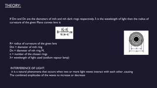
THEORY:
If Dm andDn are the diameters of mth and nth dark rings respectively. is the wavelength of light then the radius of
λ
curvature of the given Plano convex lens is
R= radius of curvature of the given lens
Dm = diameter of mth ring
Dn = diameter of nth ring M,
n = number of the chosen rings
= wavelength of light used (sodium vapour lamp)
λ
INTERFERENCE OF LIGHT:
it is a natural phenomena that occurs when two or more light waves interact with each other ,causing
The combined amplitudes of the waves to increase or decrease
5.
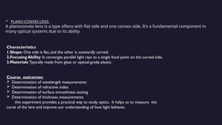
PLANO-CONVEX LENS:
Aplanoconvex lens is a type oflens with flat side and one convex side. It’s a fundamental component in
many optical systems due to its ability
Characteristics
1.Shape: One side is flat, and the other is outwardly curved.
2.Focusing Ability: It converges parallel light rays to a single focal point on the curved side.
3.Materials:Typically made from glass or optical-grade plastic.
Course outcomes:
Determination of wavelength measurements
Determination of refractive index
Determination of surface smoothness testing
Determination of thickness measurements
this experiment provides a practical way to study optics. It helps us to measure the
curve of the lens and improve our understanding of how light behaves.
6.
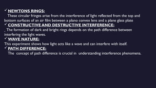
NEWTONS RINGS:
These circularfringes arise from the interference of light reflected from the top and
bottom surfaces of an air film between a plano convex lens and a plane glass plate
CONSTRUCTIVE AND DESTRUCTIVE INTERFERENCE:
The formation of dark and bright rings depends on the path difference between
interfering the light waves.
WAVE NATURE:
This experiment shows how light acts like a wave and can interfere with itself.
PATH DIFFERENCE:
The concept of path difference is crucial in understanding interference phenomena.
7.
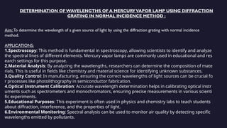
DETERMINATION OF WAVELENGTHSOF A MERCURYVAPOR LAMP USING DIFFRACTION
GRATING IN NORMAL INCIDENCE METHOD :
Aim: To determine the wavelength of a given source of light by using the diffraction grating with normal incidence
method.
APPLICATIONS:
1.Spectroscopy: This method is fundamental in spectroscopy, allowing scientists to identify and analyze
the spectral lines of different elements. Mercury vapor lamps are commonly used in educational and res
earch settings for this purpose.
2.Material Analysis: By analyzing the wavelengths, researchers can determine the composition of mate
rials. This is useful in fields like chemistry and material science for identifying unknown substances.
3.Quality Control: In manufacturing, ensuring the correct wavelengths of light sources can be crucial fo
r processes like photolithography in semiconductor fabrication.
4.Optical Instrument Calibration: Accurate wavelength determination helps in calibrating optical instr
uments such as spectrometers and monochromators, ensuring precise measurements in various scienti
fic experiments.
5.Educational Purposes: This experiment is often used in physics and chemistry labs to teach students
about diffraction, interference, and the properties of light.
6.Environmental Monitoring: Spectral analysis can be used to monitor air quality by detecting specific
wavelengths emitted by pollutants.
8.
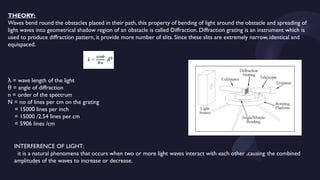
THEORY:
Waves bend roundthe obstacles placed in their path, this property of bending of light around the obstacle and spreading of
light waves into geometrical shadow region of an obstacle is called Diffraction. Diffraction grating is an instrument which is
used to produce diffraction pattern, it provide more number of slits. Since these slits are extremely narrow, identical and
equispaced.
= wave length of the light
λ
= angle of diffraction
θ
n = order of the spectrum
N = no of lines per cm on the grating
= 15000 lines per inch
= 15000 /2.54 lines per cm
= 5906 lines /cm
INTERFERENCE OF LIGHT:
it is a natural phenomena that occurs when two or more light waves interact with each other ,causing the combined
amplitudes of the waves to increase or decrease.
9.
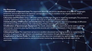
Key Outcomes:
1.Identification ofSpectral Lines:The experiment allows for the precise identification of the specific wavelengths
emitted by mercury. Each line in the spectrum corresponds to a unique transition in the mercury atoms, which is
fundamental for studying atomic structures.
2.Accuracy and Precision: Using a diffraction grating provides high accuracy in measuring wavelengths.This precision is
crucial for applications requiring exact spectral data, such as in optical instrument calibration.
3.Understanding of Diffraction and Interference:The experiment reinforces theoretical knowledge of diffraction
and interference patterns, enhancing the understanding of these essential optical phenomena.
4.Calibration of Spectroscopic Equipment:The results obtained from this experiment can be used to calibrate
spectroscopic equipment, ensuring that they provide accurate and reliable measurements in future experiments or
industrial processes.
5.EducationalValue:This experiment serves as an excellent educational tool, helping students to comprehend the
principles of spectroscopy, light behavior, and wavelength determination through practical experience.
6.Application inVarious Fields:The ability to accurately determine wavelengths has applications in fields such as
astronomy, chemistry, material science, and environmental monitoring, demonstrating the broad impact of the
experiment.
10.
DETERMINATION OF DIELECTRICCONSTANT USING CHARGING AND DISCHARGING METHOD:
AIM: To determine the dielectric constant of a given capacitor using charging and discharging method.
APPLICATIONS:
1.Material Science: Understanding the dielectric properties of materials helps in designing and developin
g new materials with specific electrical characteristics, which are crucial for advanced technologies.
2.Electronics: In the electronics industry, knowing the dielectric constant of materials is essential for desi
gning capacitors and other components that require precise electrical properties to function correctly.
3.Telecommunications: Dielectric materials are used in the construction of high-
frequency circuits and devices. Accurate measurement of dielectric properties ensures the efficient perfor
mance of communication systems.
4.Biomedical Engineering: Dielectric properties are important in medical diagnostics and treatments, suc
h as in the design of sensors and imaging devices that interact with biological tissues.
5.Environmental Monitoring: Measuring the dielectric properties of materials can help in detecting and
analyzing pollutants and other environmental factors, contributing to better environmental management
and protection.
6.Quality Control: In manufacturing, determining the dielectric constant ensures that materials meet spe
cific standards and perform reliably in their intended applications.
11.
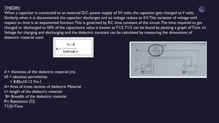
THEORY:
When a capacitoris connected to an external D.C. power supply of 5V volts, the capacitor gets charged toV volts.
Similarly, when it is disconnected, the capacitor discharges and its voltage reduce to 0V.This variation of voltage with
respect to time is an exponential function.This is governed by RC time constant of the circuit.The time required to get
charged or discharged to 50% of the capacitance value is known as T1/2.T1/2 can be found by plotting a graph of Time v/s
Voltage for charging and discharging and the dielectric constant can be calculated by measuring the dimensions of
dielectric material used.
d = thickness of the dielectric material (m)
0 = absolute permittivity
ɛ
= 8.85x10⁻¹² Fm-1
A= Area of cross section of dielectric Material
L= length of the dielectric material
B= Breadth of the dielectric material
R= Resistance ( )
Ώ
T1/2=Time
12.
KEY OUTCOMES:
• UnderstandingMaterial Properties:
•Outcome: This method provides a clear understanding of the dielectric properties of various material
s, which is essential in fields like electronics and material science.
•Benefit: It helps in selecting appropriate materials for specific applications, such as in capacitors and i
nsulators.
2. Measurement Techniques
•Outcome: Enhances skills in using measurement instruments and techniques to accurately determin
e electrical properties.
•Benefit: These skills are vital for conducting precise experiments and obtaining reliable data.
3. Data Analysis Skills
•Outcome: Develops the ability to analyze charging and discharging curves to extract meaningful infor
mation about dielectric constants.
•Benefit: This analytical capability is crucial for interpreting experimental results and making informed
conclusions.
4. Practical Application of Theory
•Outcome: Bridges the gap between theoretical knowledge and practical application by providing han
ds-on experience in a laboratory setting.
•Benefit: Reinforces understanding of electrostatics and capacitance, making theoretical concepts mor
e tangible.
rties
13.
DETERMINATION OF WAVELENGTHOF A LASER SOURCE:
AIM:
To determine the wavelength of given Laser source by using a plane diffraction Grating
APPLICATIONS:
1. Scientific Research
•Spectroscopy: Accurate wavelength measurement is crucial for spectral analysis in various scientific dis
ciplines.
•Quantum Physics: Understanding laser wavelengths is essential for experiments in quantum mechani
cs and photonics.
2. Communications
•Fiber Optics: Lasers are used in fiber optic communication. Knowing the exact wavelength ensures opt
imal data transmission and reduces signal loss.
•Telecommunications: Wavelength division multiplexing (WDM) technology relies on precise laser wave
lengths to transmit multiple signals over a single fiber.
3. Medical Applications
•Medical Imaging: Lasers of specific wavelengths are used in imaging techniques such as optical coher
ence tomography (OCT) and laser-based diagnostic tools.
•Surgery: Different laser wavelengths are used for various surgical procedures, ensuring precise and eff
ective treatments.
4. Manufacturing and Industry
•Material Processing: Lasers of specific wavelengths are used for cutting, welding, and engraving mate
rials. The wavelength affects the absorption characteristics and efficiency.
•Quality Control: Accurate wavelength determination is used in monitoring and maintaining the quality
14.
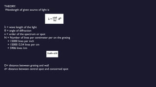
THEORY:
Wavelength of givensource of light is
= wave length of the light
λ
= angle of diffraction
θ
n = order of the spectrum or spot
N = Number of lines per centimeter per on the grating
= 15000 lines per inch
= 15000 /2.54 lines per cm
= 5906 lines /cm
D= distance between grating and wall
d= distance between central spot and concerned spot
15.
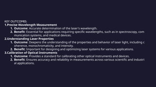
KEY OUTCOMES:
1.Precise WavelengthMeasurement
1. Outcome: Accurate determination of the laser's wavelength.
2. Benefit: Essential for applications requiring specific wavelengths, such as in spectroscopy, com
munication systems, and medical devices.
2.Understanding Laser Properties
1. Outcome: Deepens the understanding of the properties and behavior of laser light, including c
oherence, monochromaticity, and intensity.
2. Benefit: Important for designing and optimizing laser systems for various applications.
3.Calibration of Optical Instruments
1. Outcome: Provides a standard for calibrating other optical instruments and devices.
2. Benefit: Ensures accuracy and reliability in measurements across various scientific and industri
al applications.
16.
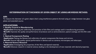
DETERMINATION OFTHICKNESS OFGIVEN OBJECT BY USING AIR WEDGE METHOD:
AIM:
To measure the diameter of a given object (hair) using interference patterns formed using air wedge between two glass
plates and extended source.
APPLICATIONS:
1. Quality Control in Manufacturing
•Application: Ensuring the uniformity and precision of thin films and coatings used in manufacturing processes.
•Benefit: Improves the quality and performance of products such as semiconductors, optical coatings, and thin-film solar
cells.
2. Optical ComponentsTesting
•Application:Testing the flatness and uniformity of optical components like lenses and mirrors.
•Benefit: Ensures high-quality optical performance in devices such as cameras, microscopes, and telescopes.
3. Material Science Research
•Application: Investigating the properties of thin films and layered materials.
•Benefit:Advances research in material science, leading to the development of new materials with desired properties.
17.
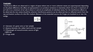
THEORY:
Interference effects areobserved in a region of space where two or more coherent waves are superimposed, depending
on the phase difference, the effect of superposition is to produce variations in intensities which vary from a maximum of
(a1+a2) 2 to a minimum of (a1-a2) 2 where a1 and a2 are amplitude of individual waves. For the interference effects to
be observed, the two waves should be coherent. Interference patterns can be observed due to reflected wave’s from the
top and bottom surface of a thin film medium. Because of the extended source, the fringes are localized at or near the
wedge.
d = diameter of a given wire or hair sample
L= distance between the rubber band and hair sample
=Wavelength of monochromatic source of light
λ
=5893 A0
= fringe width
β
18.
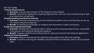
KEY OUTCOMES:
1.Precise Measurement
1.Outcome: Accurate determination of the thickness of thin objects.
2. Benefit: Essential for applications requiring high precision, such as in the manufacturing of optic
al and electronic components.
2.Understanding Interference Patterns
1. Outcome: Enhanced understanding of how interference patterns form and how they can be use
d to measure physical properties.
2. Benefit: Fundamental knowledge for students and researchers in optics and physics.
3.Improved Experimental Skills
1. Outcome: Development of practical skills in setting up and conducting experiments, using optica
l instruments, and analyzing interference patterns.
2. Benefit: Prepares students and professionals for advanced research and industrial applications.
4.Material Characterization
1. Outcome: Ability to characterize the uniformity and quality of thin films and coatings.
2. Benefit: Crucial for ensuring the reliability and performance of materials used in various technol
ogies.
19.
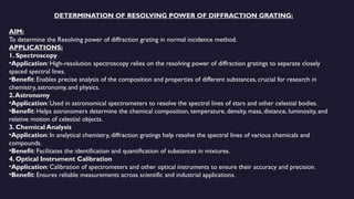
DETERMINATION OF RESOLVINGPOWER OF DIFFRACTION GRATING:
AIM:
To determine the Resolving power of diffraction grating in normal incidence method.
APPLICATIONS:
1. Spectroscopy
•Application: High-resolution spectroscopy relies on the resolving power of diffraction gratings to separate closely
spaced spectral lines.
•Benefit: Enables precise analysis of the composition and properties of different substances, crucial for research in
chemistry, astronomy, and physics.
2.Astronomy
•Application: Used in astronomical spectrometers to resolve the spectral lines of stars and other celestial bodies.
•Benefit: Helps astronomers determine the chemical composition, temperature, density, mass, distance, luminosity, and
relative motion of celestial objects.
3. Chemical Analysis
•Application: In analytical chemistry, diffraction gratings help resolve the spectral lines of various chemicals and
compounds.
•Benefit: Facilitates the identification and quantification of substances in mixtures.
4. Optical Instrument Calibration
•Application: Calibration of spectrometers and other optical instruments to ensure their accuracy and precision.
•Benefit: Ensures reliable measurements across scientific and industrial applications.
20.
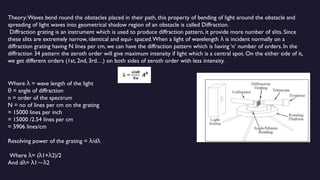
Theory:Waves bend roundthe obstacles placed in their path, this property of bending of light around the obstacle and
spreading of light waves into geometrical shadow region of an obstacle is called Diffraction.
Diffraction grating is an instrument which is used to produce diffraction pattern, it provide more number of slits. Since
these slits are extremely narrow, identical and equi- spaced.When a light of wavelength is incident normally on a
λ
diffraction grating having N lines per cm, we can have the diffraction pattern which is having ‘n’ number of orders. In the
diffraction 34 pattern the zeroth order will give maximum intensity if light which is a central spot. On the either side of it,
we get different orders (1st, 2nd, 3rd…) on both sides of zeroth order with less intensity.
Where = wave length of the light
λ
= angle of diffraction
θ
n = order of the spectrum
N = no of lines per cm on the grating
= 15000 lines per inch
= 15000 /2.54 lines per cm
= 5906 lines/cm
Resolving power of the grating = /d
λ λ
Where = ( 1+ 2)/2
λ λ λ
And d = 1 2
λ λ ⁓λ
21.
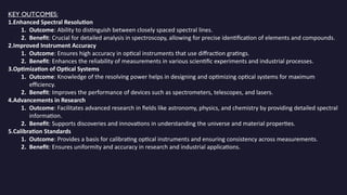
KEY OUTCOMES:
1.Enhanced SpectralResolution
1. Outcome: Ability to distinguish between closely spaced spectral lines.
2. Benefit: Crucial for detailed analysis in spectroscopy, allowing for precise identification of elements and compounds.
2.Improved Instrument Accuracy
1. Outcome: Ensures high accuracy in optical instruments that use diffraction gratings.
2. Benefit: Enhances the reliability of measurements in various scientific experiments and industrial processes.
3.Optimization of Optical Systems
1. Outcome: Knowledge of the resolving power helps in designing and optimizing optical systems for maximum
efficiency.
2. Benefit: Improves the performance of devices such as spectrometers, telescopes, and lasers.
4.Advancements in Research
1. Outcome: Facilitates advanced research in fields like astronomy, physics, and chemistry by providing detailed spectral
information.
2. Benefit: Supports discoveries and innovations in understanding the universe and material properties.
5.Calibration Standards
1. Outcome: Provides a basis for calibrating optical instruments and ensuring consistency across measurements.
2. Benefit: Ensures uniformity and accuracy in research and industrial applications.
22.
VERIFICATION OF LAWSOF STRETCHED STRING USING SONOMETER:
Aim:
To verify the laws of transverse vibrations of the stretched string by using Sonometer.
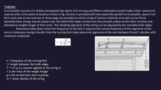
APPLICATIONS:
1. Musical Instrument Design and Tuning
•Application: Understanding the vibration of strings and the laws that govern them helps in designing and tuning musical
instruments such as guitars, violins, and pianos.
•Benefit: Ensures that the instruments produce the correct pitches and harmonics, improving the quality of sound.
2. Acoustics and Sound Engineering
•Application: The principles learned from verifying the laws of stretched strings are applied in acoustics to design and
optimize sound systems.
•Benefit: Enhances the clarity and quality of sound in various environments, such as concert halls and recording studios.
3. Material Science
•Application: Studying the properties of different string materials helps in selecting the best materials for specific
applications, such as in manufacturing and engineering.
•Benefit: Ensures durability and performance of products that rely on string vibration.
4. Physics and Engineering Education
•Application: Verifying the laws of stretched strings using a sonometer is a common experiment in physics and engineering
labs.
•Benefit: Provides hands-on experience and a deeper understanding of wave mechanics, resonance, and frequency.
23.
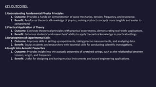
THEORY:
A sonometer consistsof a hallow rectangular box about 125 cm long and fifteen centimeters broad made a teak –wood and
covered with a thin plank of wood as shown in fig. the box is provided with two long knife parallel to its breadth, about 6 cm
form each side at one end two or three pegs are provided to which string of various materials and radii can be firmly
attached these strings may be passes over the fixed knife edges carried over tiny smooth pulleys at the other end box and
attached to weight hanger at their ends. The vibrating segments of the string can be adjusted by the movable knife edges.
Resonance takes place when the frequency of the fork is equal to the normal frequency of the segments of the
wire at resonance energy transfer from the turning fork takes place and segments of the wire between B and C vibrates with
maximum amplitude.
n = frequency of the turning fork
l = length between the knife edges
T = m1 g is a tension applied to the string m
1 is the mass of the weight hanger
g is the acceleration due to gravity
m = linear density of the string
24.
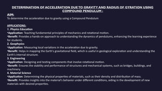
KEY OUTCOMES :
1.UnderstandingFundamental Physics Principles
1. Outcome: Provides a hands-on demonstration of wave mechanics, tension, frequency, and resonance.
2. Benefit: Reinforces theoretical knowledge of physics, making abstract concepts more tangible and easier to
comprehend.
2.Practical Application of Theory
1. Outcome: Connects theoretical principles with practical experiments, demonstrating real-world applications.
2. Benefit: Enhances students' and researchers' ability to apply theoretical knowledge in practical settings.
3.Development of Experimental Skills
1. Outcome: Improves skills in setting up experiments, taking precise measurements, and analyzing data.
2. Benefit: Equips students and researchers with essential skills for conducting scientific investigations.
4.Insight into Acoustic Properties
1. Outcome: Provides insight into the acoustic properties of stretched strings, such as the relationship between
tension, length, and frequency.
2. Benefit: Useful for designing and tuning musical instruments and sound engineering applications.
25.
DETERMINATION OF ACCELERATIONDUETO GRAVITY AND RADIUS OF GYRATION USING
COMPOUND PENDULUM :
AIM:
To determine the acceleration due to gravity using a Compound Pendulum
APPLICATIONS:
1. Physics Education
•Application: Teaching fundamental principles of mechanics and rotational motion.
•Benefit: Provides a hands-on approach to understanding the dynamics of pendulums, enhancing the learning experience
for students.
2. Geophysics
•Application: Measuring local variations in the acceleration due to gravity.
•Benefit: Helps in mapping the Earth's gravitational field, which is useful in geological exploration and understanding the
Earth's internal structure.
3. Engineering
•Application: Designing and testing components that involve rotational motion.
•Benefit: Ensures the stability and performance of structures and mechanical systems, such as bridges, buildings, and
machinery.
4. Material Science
•Application: Determining the physical properties of materials, such as their density and distribution of mass.
•Benefit: Provides insights into the material's behavior under different conditions, aiding in the development of new
materials with desired properties.
26.
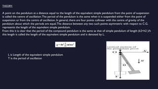
THEORY:
A point onthe pendulum at a distance equal to the length of the equivalent simple pendulum from the point of suspension
is called the centre of oscillation.The period of the pendulum is the same when it is suspended either from the point of
suspension or from the centre of oscillation. In general, there are four points collinear with the centre of gravity of the
pendulum about which the periods are equal.The distance between any two such points asymmetric with respect to C.G.
represents the length of the equivalent simple pendulum.
From this it is clear that the period of the compound pendulum is the same as that of simple pendulum of length (k2+h2 )/h
this length is called the length of the equivalent simple pendulum and is denoted by L.
L is Length of the equivalent simple pendulum
T is the period of oscillation
27.
KEY OUTCOMES:
1.Accurate Measurementof g
1. Outcome: Provides a precise measurement of the local acceleration due to gravity.
2. Benefit: Important for geophysical studies and calibrating other gravitational measurement instruments.
2.Understanding Rotational Dynamics
1. Outcome: Enhances comprehension of rotational motion, moments of inertia, and the physics of pendulums.
2. Benefit: Foundational knowledge for advanced studies in physics and engineering.
3.Practical Application of Theoretical Concepts
1. Outcome: Demonstrates the practical application of theoretical principles such as torque, angular velocity, and
oscillatory motion.
2. Benefit: Bridges the gap between theory and practice, reinforcing learning through experimentation.
4.Development of Experimental Skills
1. Outcome: Improves skills in setting up experiments, conducting precise measurements, and analyzing data.
2. Benefit: Equips students and researchers with essential scientific techniques and methodologies.
28.
DETERMINATION OF TEMPERATURECOEFFICIENT OF A THERMISTOR:
AIM:
To determine the temperature coefficient of a thermistor.
APPLICATIONS:
1. Temperature Measurement and Control
•Application: Used in temperature sensors for precise measurement and control in various systems.
•Benefit: Provides accurate temperature readings in HVAC systems, industrial processes, and consumer electronics, ensuring
optimal performance.
2. Overcurrent Protection
•Application: Thermistors with known temperature coefficients are used in circuits to protect against overcurrent conditions.
•Benefit: Prevents damage to electronic components by limiting current flow during high temperature or overcurrent events.
3. Battery Management Systems
•Application: Monitoring the temperature of batteries to ensure they operate within safe limits.
•Benefit: Extends battery life and enhances safety by preventing overheating and thermal runaway in rechargeable batteries.
4. Climate Control Systems
•Application: Used in automotive and building climate control systems to monitor and regulate temperature.
•Benefit: Ensures comfortable and efficient operation of heating, ventilation, and air conditioning systems.
29.
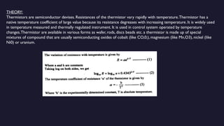
THEORY:
Thermistors are semiconductordevises. Resistances of the thermistor vary rapidly with temperature.Thermistor has a
native temperature coefficient of large value because its resistance degreases with increasing temperature. It is widely used
in temperature measured and thermally regulated instrument. It is used in control system operated by temperature
changes.Thermistor are available in various forms as wafer, rods, discs beads etc. a thermistor is made up of special
mixtures of compound that are usually semiconducting oxides of cobalt (like CO,0;), magnesium (like Mn,O3), nickel (like
Ni0) or uranium.
30.
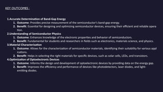
KEY OUTCOMES:
1.Accurate TemperatureMeasurement
1. Outcome: Provides precise data on how the resistance of a thermistor changes with temperature.
2. Benefit: Essential for designing accurate temperature sensing and control systems in various industries.
2.Understanding Material Properties
1. Outcome: Enhances knowledge of the thermal and electrical properties of thermistor materials.
2. Benefit: Helps in selecting the right materials for specific applications, ensuring optimal performance and reliability.
3.Development of Temperature Sensors
1. Outcome: Facilitates the creation of efficient and responsive temperature sensors.
2. Benefit: Improves the accuracy and functionality of devices in fields such as automotive, electronics, and medical equip
ment.
4.Design and Optimization of Circuits
1. Outcome: Provides data necessary for designing circuits that incorporate thermistors for temperature compensation or
protection.
2. Benefit: Ensures the stability and efficiency of electronic devices under varying thermal conditions.
31.
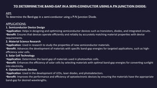
TO DETERMINETHE BAND-GAPIN A SEMI-CONDUCTOR USING A PN JUNCTION DIODE:
AIM:
To determine the Band-gap in a semi-conductor using a P-N Junction Diode.
APPLICATIONS:
1. Semiconductor Device Design
•Application: Helps in designing and optimizing semiconductor devices such as transistors, diodes, and integrated circuits.
•Benefit: Ensures that devices operate efficiently and reliably by accurately matching material properties with device
requirements.
2. Material Science Research
•Application: Used in research to study the properties of new semiconductor materials.
•Benefit: Advances the development of materials with specific band-gap energies for targeted applications, such as high-
efficiency solar cells.
3. Solar Cell Technology
•Application: Determines the band-gap of materials used in photovoltaic cells.
•Benefit: Enhances the efficiency of solar cells by selecting materials with optimal band-gap energies for converting sunlight
into electricity.
4. Optoelectronic Devices
•Application: Used in the development of LEDs, laser diodes, and photodetectors.
•Benefit: Improves the performance and efficiency of optoelectronic devices by ensuring the materials have the appropriate
band-gap for desired wavelengths.
32.
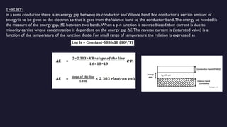
THEORY:
In a semiconductor there is an energy gap between its conductor andValance band. For conductor a certain amount of
energy is to be given to the electron so that it goes from theValance band to the conductor band.The energy so needed is
the measure of the energy gap, ∆E, between two bands.When a p-n junction is reverse biased then current is due to
minority carries whose concentration is dependent on the energy gap ∆E.The reverse current is (saturated valve) is a
function of the temperature of the junction diode. For small range of temperature the relation is expressed as
33.
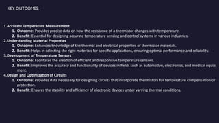
KEY OUTCOMES :
1.AccurateDetermination of Band-Gap Energy
1. Outcome: Provides precise measurement of the semiconductor's band-gap energy.
2. Benefit: Essential for designing and optimizing semiconductor devices, ensuring their efficient and reliable opera
tion.
2.Understanding of Semiconductor Physics
1. Outcome: Enhances knowledge of the electronic properties and behavior of semiconductors.
2. Benefit: Fundamental for students and researchers in fields such as electronics, materials science, and physics.
3.Material Characterization
1. Outcome: Allows for the characterization of semiconductor materials, identifying their suitability for various appl
ications.
2. Benefit: Helps in selecting the right materials for specific devices, such as solar cells, LEDs, and transistors.
4.Optimization of Optoelectronic Devices
1. Outcome: Informs the design and development of optoelectronic devices by providing data on the energy gap.
2. Benefit: Improves the efficiency and performance of devices like photodetectors, laser diodes, and light-
emitting diodes.