Download to read offline
![©Copyright 2002-2006 SD Card Association
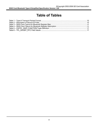
SDIO Card Bluetooth Type-A Simplified Specification Version 1.00
13
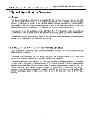
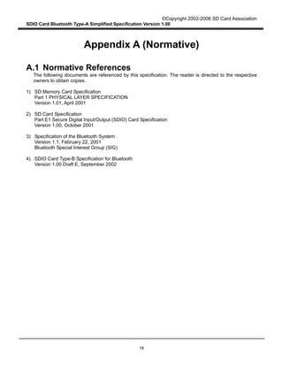
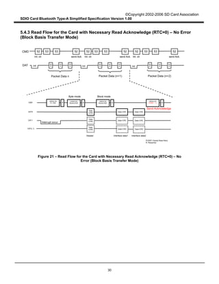
4.3.2 Byte Basis Transfer Mode
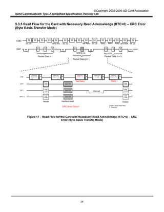
This section describes the way of keeping packet boundary and recovering from CRC errors in Byte
Basis transfer mode. See Appendix D for details of data transfer operation.
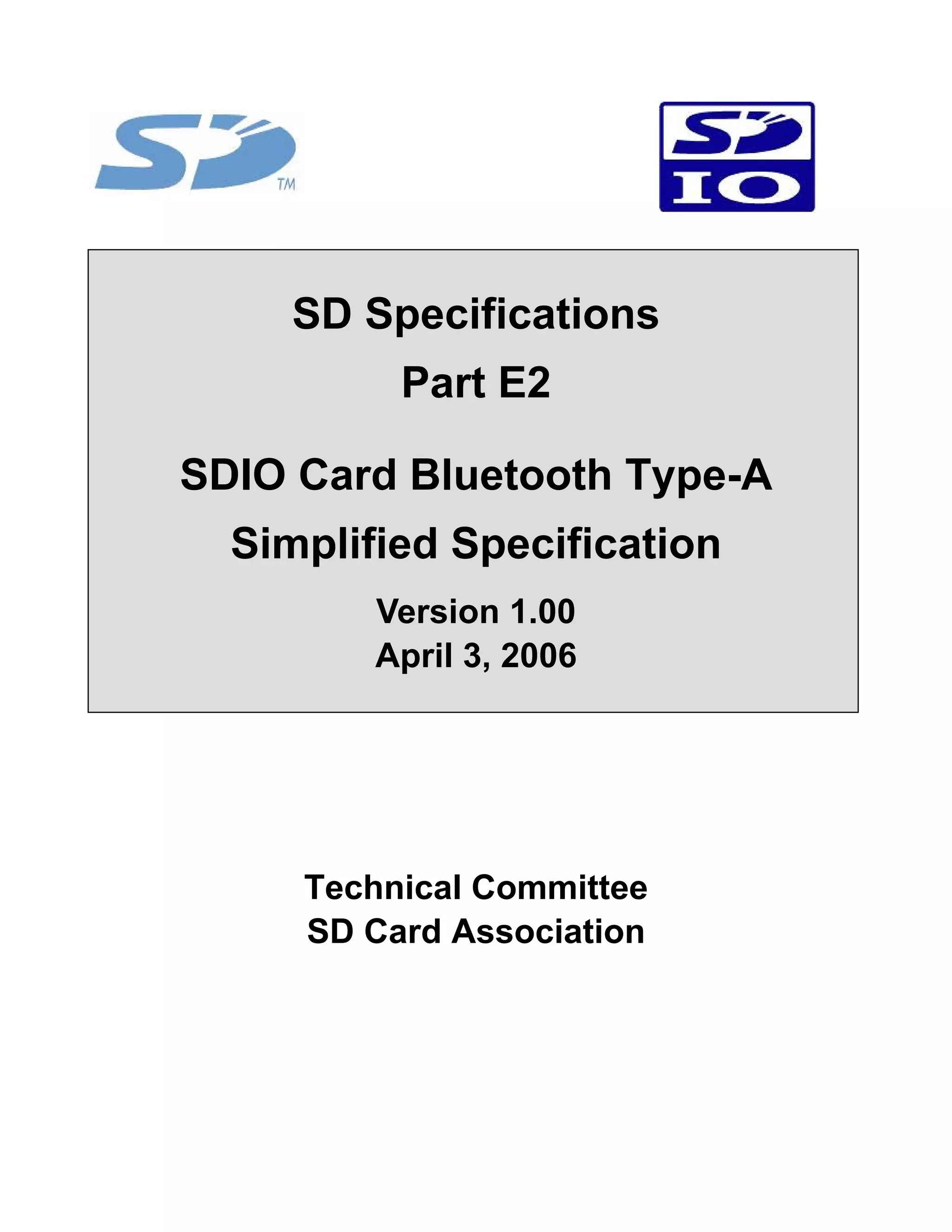
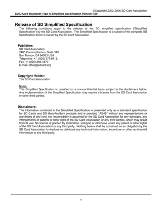
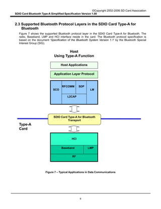
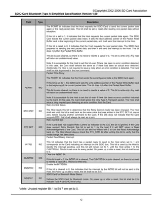
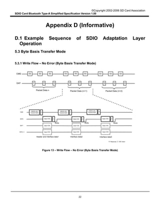
Figure 8 describes the Type-A Transport packet Write operation from the Host to the Card in Byte Basis
transfer mode. When the Type-A Transport in the Host writes a packet to the Card through the SDIO
Interface, it divides the Type-A Transport packet into several SDIO data packets. Assuming that L
denotes the length of a Type-A Transport packet (in bytes) and B denotes the maximum byte count in
Byte Basis transfer mode (B < L). There are [L / B] SDIO data packets to be sent. The Type-A Transport
in the Host repeatedly sends all SDIO data packets using Byte Basis transfer mode until all the SDIO
data packets are sent. In Figure 8, the maximum transfer size is used in each SDIO data. However,
smaller byte counts may also be used for this purpose.
When a CRC error occurs in an SDIO transmission, the Type-A Transport in the Host recognizes it
through the transmission result and it sets the PCWRT field to "1" in order to prepare for a re-write.
Then it shall try to re-send the whole Type-A Transport data packet, including the erroneous SDIO data
packet, until the erroneous packet is sent successfully or a number of retries designated by the Host are
reached. If the packet is not sent successfully, the Type-A Transport sends a fatal error to the Host
application. The Host application should reset the Type-A Transport to resume Bluetooth
communication.
Figure 8 – Type-A Transport Packet Write Operation from the Host to the Card in Byte
Basis Transfer Mode
Length (3 Bytes) Interface data (L-4 Bytes)
Data (B Bytes)
SDIO
Protocol
Multiplexing
Adaptation
Type-A Transport
SDIO Data (B Bytes) SDIO Data (B Bytes) SDIO Data (B Bytes)
Byte Basis mode Byte Basis mode Byte Basis mode
When CRC error occurs in transmission, the Type-A Transport packet is re-sent
SDIO Data
(L mod B Bytes)
Service ID (1 Byte)
Data (B Bytes) Data (B Bytes) Data (L mod B Bytes)
Byte Basis mode](https://image.slidesharecdn.com/parte2100-150826141053-lva1-app6891/85/Part-e2-100-20-320.jpg)
![©Copyright 2002-2006 SD Card Association
SDIO Card Bluetooth Type-A Simplified Specification Version 1.00
15
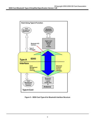
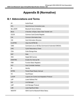
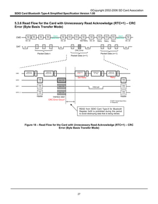
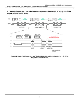
4.3.3 Block Basis Transfer Mode
This section describes the way of keeping packet boundary and recovering from CRC errors in Block
Basis transfer mode. Block Basis transfer mode has the advantages of less host resource consumption
and high speed SDIO transfer due to elimination of host intervention during SDIO data transfer. Block
Basis transfer mode is optional in the SDIO specification. However, the Type-A Transport requires an
error free transport over SDIO, therefore error recovery procedure must be implemented if Block Basis
transfer mode is supported.
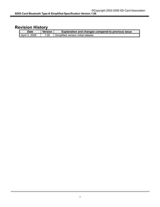
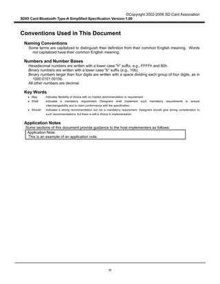
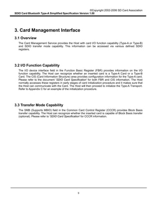
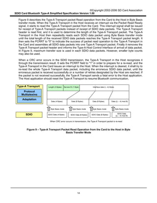
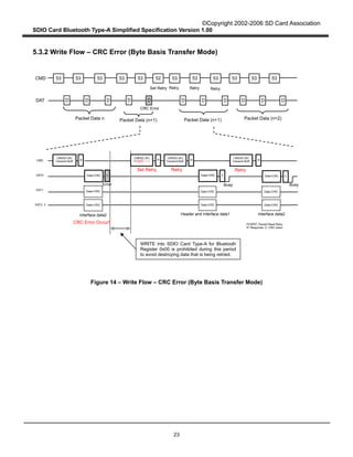
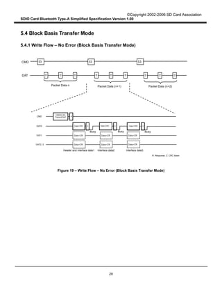
Figure 10 describes the Type-A Transport packet Write operation from the Host to the Card in Block
Basis transfer mode. When the Type-A Transport in the Host writes a packet to the Card through SDIO
Interface, it divides the Type-A Transport packet into several SDIO data packets. Assuming that L
denotes the length of Type-A transport packet (in bytes) and B denotes maximum byte count in Byte
Basis transfer mode (B < L), there are [L / B] SDIO data packets to be sent. The Type-A Transport then
writes the whole Type-A Transport packet as SDIO data packets concatenated with Block Basis transfer
mode.
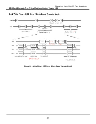
When a CRC error occurs in an SDIO transmission, the Type-A Transport in the Host determines it
through the transmission result. It aborts multi bock transfer and sets the PCWRT field to "1" in order to
prepare for a re-write. It shall then try to re-send the whole Type-A Transport data packet, until the
erroneous packet is sent successfully or a number of retries designated by the Host are reached. If the
packet is not sent successfully, the Type-A Transport sends a fatal error to the Host application. The
Host application should reset the Type-A Transport to resume Bluetooth communication.
Figure 10 – Type-A Transport Packet Write Operation from the Host to the Card in Block
Basis Transfer Mode
Figure 11 describes the Type-A Transport packet Read operation from the Card to the Host in Block
Length (3 Bytes) Interface data (L-4 Bytes)
Data (B Bytes) Data (B Bytes) Data (B Bytes) Data (L mod B)
SDIO SDIO Data (B Bytes) SDIO Data (B Bytes) SDIO Data (B Bytes) SDIO Data
(L mod B)
Block Basis mode
When CRC error occurs in transmission, the Type-A Transport packet is re-sent
Service ID (1 Byte)
Protocol
Multiplexing
Adaptation
Type-A Transport](https://image.slidesharecdn.com/parte2100-150826141053-lva1-app6891/85/Part-e2-100-22-320.jpg)

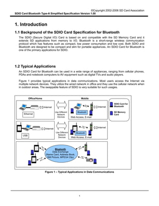
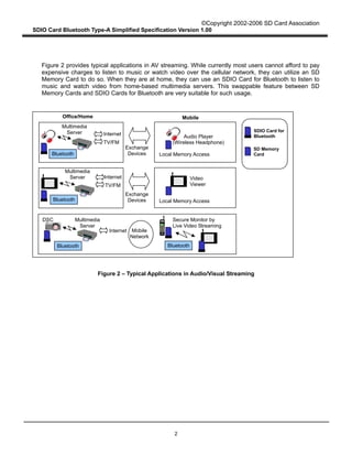
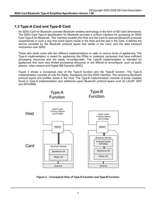
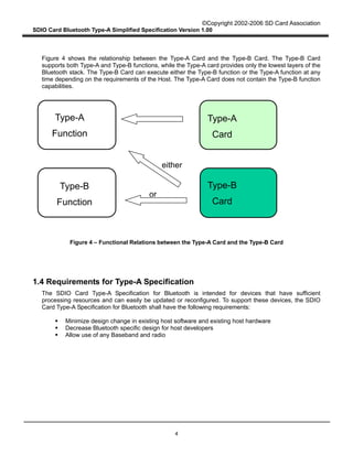
This document provides an overview and simplified specification for SDIO Card Type-A for Bluetooth: - It defines the interface between a host and an SDIO Card for Bluetooth, which provides a Bluetooth radio and baseband functionality. - The Type-A card interface provides only an HCI interface to the host, using SDIO commands to enable reliable and unreliable data transfer modes. - It scopes the specification to Type-A cards, which are intended for hosts with sufficient processing capabilities like PDAs and laptops. Type-B cards provide more Bluetooth protocol layers and are for devices with limited processing like audio players.