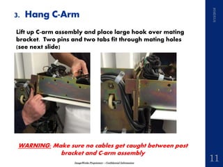
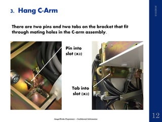
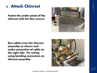
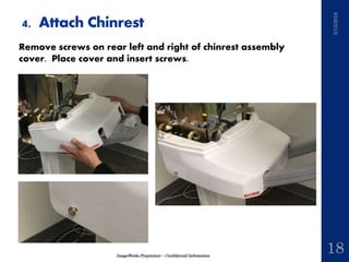
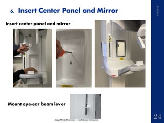
Panoura 18S
Three Box Packaging Assembly Quick Guide
ImageWorks Proprietary – Confidential Information
These instructions serve as supplemental assembly guidance of
the Panoura. They are not meant to replace the installation
manual, but rather serve to complement it.
If there are any questions, please do not hesitate to contact us
914-592-6100
5/15/2016
2
Summary
ImageWorks Proprietary – Confidential Information
1. Packaging Contents
2. Install Post
3. Hang C-Arm
4. Attach Chinrest
5. Attach Head Support
6. Insert Side Covers
7. Insert Center Panel and Mirrors
5/15/2016
3
Agenda
ImageWorks Proprietary – Confidential Information
Basic Pan arrives in three boxes containing:
1. Post
2. C-Arm Assembly, Sensor and Components
3. Accessories
5/15/2016
4
1. Package Contents
ImageWorks Proprietary – Confidential Information
5/15/2016
5
• Unbox and install the post
• Fasten post to the ground following installation
manual (picture below with a base stand).
2. Install Post
ImageWorks Proprietary – Confidential Information
5/15/2016
6
Remove box from C-Arm package by removing 4 screws
attaching box to skid
3. Hang C-Arm
ImageWorks Proprietary – Confidential Information
5/15/2016
7
Remove sensor
package
Remove top cover from
c-arm by removing 4
screws.
3. Hang C-Arm
ImageWorks Proprietary – Confidential Information
5/15/2016
8
Move C-Arm assembly
into position in front of
post
Remove bolts from c-
arm chassis bracket
3. Hang C-Arm
ImageWorks Proprietary – Confidential Information
5/15/2016
9
WARNING: Bolts must be fully removed from
chassis to prevent damage upon installation
Remove bolts that fix C-Arm assembly to wooden frame
3. Hang C-Arm
ImageWorks Proprietary – Confidential Information
5/15/2016
10
WARNING:
Damage can occur if
install is done
without moving
drive unit
Move driving unit by rotating coupling of x-axis motor by hand
so as not to hit slide body with rotating arm during assembly
3. Hang C-Arm
ImageWorks Proprietary – Confidential Information
5/15/2016
11
WARNING: Make sure no cables get caught between post
bracket and C-arm assembly
Lift up C-arm assembly and place large hook over mating
bracket. Two pins and two tabs fit through mating holes
(see next slide)
3. Hang C-Arm
ImageWorks Proprietary – Confidential Information
5/15/2016
12
There are two pins and two tabs on the bracket that fit
through mating holes in the C-arm assembly.
Pin into
slot (x2)
Tab into
slot (x2)
3. Hang C-Arm
ImageWorks Proprietary – Confidential Information
5/15/2016
13
• Place and tighten four bolts to fasten C-Arm to Post
• Pull cable assembly up through hole in C-Arm Chassis, and
make 7 wiring connections (for Pan Unit without ceph)
3. Hang C-Arm
ImageWorks Proprietary – Confidential Information
5/15/2016
14
Run Ethernet cable down
through same hole. Make
sure cable is above the
support tray (otherwise front
panel will not fit).
Remove panel box on rear
of unit and connect Ethernet
to port in box. Reattach
panel box.
3. Hang C-Arm
ImageWorks Proprietary – Confidential Information
5/15/2016
15
Check leveling of the unit following 2.2.4 Leveling in the
Installation Manual
Note: In the case of Ceph unit, check the level after
installation of the unit as following “2.9 Cephalometric Unit
Mounting” in the Installation Manual
3. Hang C-Arm
ImageWorks Proprietary – Confidential Information
5/15/2016
16
Attach chinrest assembly
over 2 pins and screw to
chinrest bracket on post (4
screws).
To attach chinrest
assembly, remove 4 bolts
from chinrest bracket.
4. Attach Chinrest
ImageWorks Proprietary – Confidential Information
5/15/2016
17
Fasten the under panel of the
chinrest with the four screws.
Run cables over the chinrest
assembly as shown and
make connection of cable on
the right side. Fix wiring
using banding connectors on
chinrest assembly.
4. Attach Chinrest
ImageWorks Proprietary – Confidential Information
5/15/2016
18
Remove screws on rear left and right of chinrest assembly
cover. Place cover and insert screws.
4. Attach Chinrest
ImageWorks Proprietary – Confidential Information
5/15/2016
19
Insert and attach underside
cover with 5 screws and
connect connector
4. Attach Head Support
Remove cap4 screws on the
head support fastening
bracket
ImageWorks Proprietary – Confidential Information
5/15/2016
20
Connect the connector on
the head support unit to the
connector on the driving
part
4. Attach Head Support
ImageWorks Proprietary – Confidential Information
5/15/2016
21
Refer to the figure. Put the connector in the connector holder
on the head support disc and fasten the head support unit
using the 4 screws
NOTE: When mounting the head support unit, make sure that
the connector is placed in the connector holder on the head
support disc. Beware that the harness is not caught between
when the screws are fastened
4. Attach Head Support
ImageWorks Proprietary – Confidential Information
5/15/2016
22
Remove left side cover from packaging
5. Insert Side Covers
Make cabling connection to inside of keypad (K1, K3-K7, K2
for Ceph unit)
ImageWorks Proprietary – Confidential Information
5/15/2016
23
Fasten left side and right side panels
5. Insert Side Covers
ImageWorks Proprietary – Confidential Information
5/15/2016
24
Insert center panel and mirror
Mount eye-ear beam lever
6. Insert Center Panel and Mirror
ImageWorks Proprietary – Confidential Information
5/15/2016
25
Continue with standard installation procedure from
installation manual

Panoura 18S Assembly Quick Guide

  • 1.
    Panoura 18S Three BoxPackaging Assembly Quick Guide
  • 2.
    ImageWorks Proprietary –Confidential Information These instructions serve as supplemental assembly guidance of the Panoura. They are not meant to replace the installation manual, but rather serve to complement it. If there are any questions, please do not hesitate to contact us 914-592-6100 5/15/2016 2 Summary
  • 3.
    ImageWorks Proprietary –Confidential Information 1. Packaging Contents 2. Install Post 3. Hang C-Arm 4. Attach Chinrest 5. Attach Head Support 6. Insert Side Covers 7. Insert Center Panel and Mirrors 5/15/2016 3 Agenda
  • 4.
    ImageWorks Proprietary –Confidential Information Basic Pan arrives in three boxes containing: 1. Post 2. C-Arm Assembly, Sensor and Components 3. Accessories 5/15/2016 4 1. Package Contents
  • 5.
    ImageWorks Proprietary –Confidential Information 5/15/2016 5 • Unbox and install the post • Fasten post to the ground following installation manual (picture below with a base stand). 2. Install Post
  • 6.
    ImageWorks Proprietary –Confidential Information 5/15/2016 6 Remove box from C-Arm package by removing 4 screws attaching box to skid 3. Hang C-Arm
  • 7.
    ImageWorks Proprietary –Confidential Information 5/15/2016 7 Remove sensor package Remove top cover from c-arm by removing 4 screws. 3. Hang C-Arm
  • 8.
    ImageWorks Proprietary –Confidential Information 5/15/2016 8 Move C-Arm assembly into position in front of post Remove bolts from c- arm chassis bracket 3. Hang C-Arm
  • 9.
    ImageWorks Proprietary –Confidential Information 5/15/2016 9 WARNING: Bolts must be fully removed from chassis to prevent damage upon installation Remove bolts that fix C-Arm assembly to wooden frame 3. Hang C-Arm
  • 10.
    ImageWorks Proprietary –Confidential Information 5/15/2016 10 WARNING: Damage can occur if install is done without moving drive unit Move driving unit by rotating coupling of x-axis motor by hand so as not to hit slide body with rotating arm during assembly 3. Hang C-Arm
  • 11.
    ImageWorks Proprietary –Confidential Information 5/15/2016 11 WARNING: Make sure no cables get caught between post bracket and C-arm assembly Lift up C-arm assembly and place large hook over mating bracket. Two pins and two tabs fit through mating holes (see next slide) 3. Hang C-Arm
  • 12.
    ImageWorks Proprietary –Confidential Information 5/15/2016 12 There are two pins and two tabs on the bracket that fit through mating holes in the C-arm assembly. Pin into slot (x2) Tab into slot (x2) 3. Hang C-Arm
  • 13.
    ImageWorks Proprietary –Confidential Information 5/15/2016 13 • Place and tighten four bolts to fasten C-Arm to Post • Pull cable assembly up through hole in C-Arm Chassis, and make 7 wiring connections (for Pan Unit without ceph) 3. Hang C-Arm
  • 14.
    ImageWorks Proprietary –Confidential Information 5/15/2016 14 Run Ethernet cable down through same hole. Make sure cable is above the support tray (otherwise front panel will not fit). Remove panel box on rear of unit and connect Ethernet to port in box. Reattach panel box. 3. Hang C-Arm
  • 15.
    ImageWorks Proprietary –Confidential Information 5/15/2016 15 Check leveling of the unit following 2.2.4 Leveling in the Installation Manual Note: In the case of Ceph unit, check the level after installation of the unit as following “2.9 Cephalometric Unit Mounting” in the Installation Manual 3. Hang C-Arm
  • 16.
    ImageWorks Proprietary –Confidential Information 5/15/2016 16 Attach chinrest assembly over 2 pins and screw to chinrest bracket on post (4 screws). To attach chinrest assembly, remove 4 bolts from chinrest bracket. 4. Attach Chinrest
  • 17.
    ImageWorks Proprietary –Confidential Information 5/15/2016 17 Fasten the under panel of the chinrest with the four screws. Run cables over the chinrest assembly as shown and make connection of cable on the right side. Fix wiring using banding connectors on chinrest assembly. 4. Attach Chinrest
  • 18.
    ImageWorks Proprietary –Confidential Information 5/15/2016 18 Remove screws on rear left and right of chinrest assembly cover. Place cover and insert screws. 4. Attach Chinrest
  • 19.
    ImageWorks Proprietary –Confidential Information 5/15/2016 19 Insert and attach underside cover with 5 screws and connect connector 4. Attach Head Support Remove cap4 screws on the head support fastening bracket
  • 20.
    ImageWorks Proprietary –Confidential Information 5/15/2016 20 Connect the connector on the head support unit to the connector on the driving part 4. Attach Head Support
  • 21.
    ImageWorks Proprietary –Confidential Information 5/15/2016 21 Refer to the figure. Put the connector in the connector holder on the head support disc and fasten the head support unit using the 4 screws NOTE: When mounting the head support unit, make sure that the connector is placed in the connector holder on the head support disc. Beware that the harness is not caught between when the screws are fastened 4. Attach Head Support
  • 22.
    ImageWorks Proprietary –Confidential Information 5/15/2016 22 Remove left side cover from packaging 5. Insert Side Covers Make cabling connection to inside of keypad (K1, K3-K7, K2 for Ceph unit)
  • 23.
    ImageWorks Proprietary –Confidential Information 5/15/2016 23 Fasten left side and right side panels 5. Insert Side Covers
  • 24.
    ImageWorks Proprietary –Confidential Information 5/15/2016 24 Insert center panel and mirror Mount eye-ear beam lever 6. Insert Center Panel and Mirror
  • 25.
    ImageWorks Proprietary –Confidential Information 5/15/2016 25 Continue with standard installation procedure from installation manual