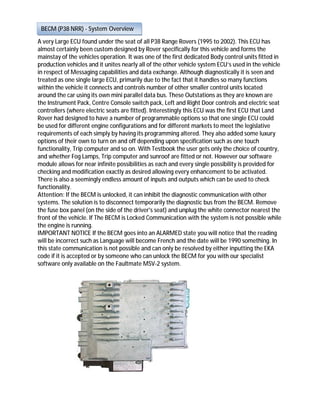
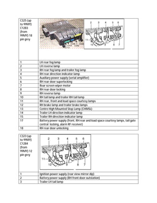
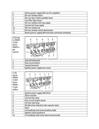
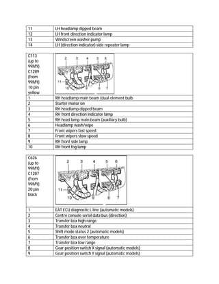
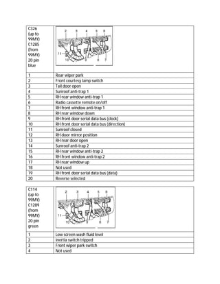
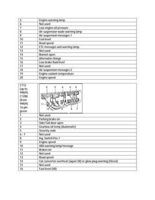
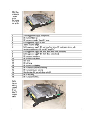
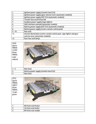
The document discusses the Body Electronic Control Module (BECM) used in 1995-2002 Land Rover Range Rover P38 vehicles. The BECM is a large, custom-designed ECU that controls many vehicle functions and communicates with other control units. It allows for programming of options and features. The BECM has diagnostic capabilities that allow checking communication with key fobs and other control units connected to its network.
O documento descreve a localização e especificações dos sistemas de luzes, indicadores e interruptores da motocicleta XR250, incluindo informações sobre substituição de lâmpadas e diagnóstico de defeitos no painel de instrumentos.
Thank you for purchasing what PSI has designed as the most up-to-date and easiest to install automotive
fuel injection harness on the market. This harness is designed to be a complete wiring harness for the fuel
injection system on General Motors 1998 and newer LS1/LS6 fuel injected engines with Drive By Cable
Throttle Body and 4L60E or 4L80E transmission.
This harness is constructed with GM Delphi Connectors and Terminals with GXL/TXL (600 volt
polyethylene cross-linked) wire which is professionally assembled and 100% quality inspected prior to
shipping. This harness includes all wiring that is needed by the PCM to run and control the fuel injection
system and transmission.
Manual de serviço xlx250 r (1984) mskb7841p manutencThiago Huari
Este documento fornece instruções de manutenção para uma motocicleta XLX250R, incluindo: (1) uma tabela de manutenção programada com itens e intervalos; (2) especificações técnicas do motor e chassi; e (3) procedimentos de manutenção detalhados para vários componentes como filtro de ar, vela de ignição, folga das válvulas, corrente de transmissão e freios.
This document contains wiring diagrams for a 1989 Toyota Corolla. It includes 14 figures that show the wiring diagrams for various electrical components and systems, such as the engine, computer engine control, fuse blocks, heating and air conditioning, instruments, anti-theft system, door locks, and passenger compartment. The diagrams are intended to help identify component locations and electrical connections for the Toyota Corolla.
Este documento proporciona una tabla de códigos de problemas de diagnóstico para vehículos. La tabla incluye más de 100 códigos de diagnóstico con sus posibles causas y páginas de referencia. Cada código está asociado con uno o más síntomas como falta de arranque, baja potencia o encendido de la luz de chequeo del motor. La tabla proporciona una guía para diagnosticar y resolver problemas en el vehículo basada en los códigos de diagnóstico detectados.
Manual de serviço cg125 titan ks es kse cg125 cargo (2002) cabecoteThiago Huari
Este documento fornece instruções para serviços no cabeçote e válvulas de um motor, incluindo diagnóstico de defeitos, teste de compressão, remoção e inspeção do cabeçote, substituição de guias de válvulas, e especificações.
This document provides information about the electrical system of a Sinotruk vehicle. It includes 3 sections:
1. An overview of the main electrical parts and their functions.
2. Instructions on how to operate parts like the headlights, fog lights, brake lights, wipers and more.
3. Diagrams of electrical circuits and principles to explain how systems like the headlights, starter, and instruments work. Troubleshooting tips are also provided.
As 3 frases resumem os principais documentos:
1) Os documentos fornecem informações sobre a localização e função dos relês e fusíveis em diferentes modelos de veículos da GM.
2) São descritos os locais da caixa de relês internas e no compartimento do motor, com as funções dos principais relês em cada veículo.
3) As informações variam de acordo com o modelo e ano do veículo, mas fornecem detalhes essenciais sobre a finalidade de cada relé e fusível.
Este documento proporciona una lista de componentes electrónicos y eléctricos de un vehículo, incluyendo sensores, interruptores, relés, motores, baterías y conectores. La lista contiene cientos de elementos organizados por códigos alfanuméricos y descripciones breves.
Manual serviço c 100 biz c-100 biz es c-100 biz+ (2002) - 00 x6b-gce-763 luzesThiago Huari
O documento fornece instruções para inspeção e substituição de lâmpadas e componentes elétricos em uma motocicleta, incluindo:
1) Procedimentos para substituir lâmpadas de farol, sinalizadores, lanterna traseira e instrumentos;
2) Métodos para inspecionar interruptores de freio, ponto morto, ignição e outros;
3) Orientações para testar o sensor de combustível e buzina.
BOMBA STANADYNE DE2635-6237 RE-557897 JOHN DEERE Junior Iung
The document provides specifications for an injection pump model DE2635-6237, including operating speeds, calibration checks, settings, and applicable service assemblies. It lists pump details like full load RPM, customer/engine information, application, model/part numbers. Calibration is to be done on a test stand using specified lines, injectors, and fluid at given temperatures and pressures. Installation and name plate details are provided. Calibration checks include measuring parameters like fuel delivery, cylinder variation, and shutdown delivery at various pump speeds and settings. Applicable service kits and a history of document revisions are also included.
O documento apresenta um sumário sobre o sistema de injeção eletrônica, direção elétrica e rede CAN do veículo Stilo da Fiat. O texto descreve os principais componentes dos sistemas, como o ECU, reles, sensores e atuadores, e fornece esquemas elétricos para auxiliar na compreensão do funcionamento.
La industria automotriz sigue en la vanguardia del mundo de la mecanica y la electronica en este manual encontrara detalles que puedan servir en la reparacion y diagnostico de tu vehiculo
Manual de serviço shadow 750 00 x6b-meg-001 diagrama-eletricoThiago Huari
1. O documento apresenta o diagrama elétrico da motocicleta Honda Shadow 750.
2. São mostrados os componentes elétricos e seus respectivos circuitos, incluindo fusíveis, lâmpadas, interruptores e cabos.
3. O diagrama identifica as partes do sistema elétrico e fornece informações sobre a cor e número de fios para cada circuito.
Manual de serviço shadow 750 00 x6b-meg-001 manutencaoThiago Huari
Este documento fornece instruções de manutenção para a motocicleta Shadow 750, incluindo:
1) Uma tabela de manutenção com itens e períodos de manutenção recomendados;
2) Instruções para verificar e ajustar itens como a linha de combustível, acelerador, afogador, filtros de ar, vela de ignição, válvulas, óleos, freios e outros sistemas.
Este documento proporciona una descripción general de la transmisión automática Renault-Peugeot DP0-AL4. Explica su estructura, componentes, aplicaciones, posibles fallas y recomendaciones para el ensamble y ajuste. Se enfoca en los embragues E1, E2 y F1, y ofrece detalles sobre su instalación y pruebas de funcionamiento. También cubre otros elementos como las bandas, planetarios, bomba y cuerpo de válvulas.
O documento apresenta um diagrama elétrico detalhado de um veículo, mostrando a localização e conexões de componentes como luzes, buzina, motor de partida e sistema de carga. É descrito o layout da caixa de fusíveis e suas respectivas funções.
O documento fornece informações sobre a pinagem de ECUs importadas para vários modelos de veículos, incluindo Audi, BMW, Chrysler, Dodge, Jeep e Mercedes. Ele lista os pinos e suas respectivas funções para cada tipo de ECU.
Manaul de serviço cbr900 rr fireblade (~1999) alimentaThiago Huari
O documento fornece instruções para serviço e diagnóstico de defeitos do sistema de alimentação de um modelo CBR900RR. Detalha os procedimentos para remoção, desmontagem, limpeza e montagem dos carburadores, incluindo a remoção das bóias, agulhas e válvulas. Fornece especificações técnicas e valores de torque recomendados para as peças.
Manual serviço c 100 biz c-100 biz es c-100 biz+ (2002) - 00 x6b-gce-763 bateriaThiago Huari
Este documento fornece informações sobre a bateria e o sistema de carga da motocicleta C-100 BIZ. Inclui especificações técnicas, procedimentos de inspeção, diagnóstico de defeitos e instruções de segurança.
1. O documento fornece informações sobre a pinagem de vários tipos de ECUs de sistemas de injeção eletrônica de combustível de veículos Fiat, GM, Volkswagen e Ford.
2. São listadas as pinagens de ECUs como Motronic, MonoMotronic, Digifant, entre outros usados nesses fabricantes.
3. Para cada ECU é fornecida a numeração e função de cada pino, facilitando o diagnóstico e reparo desses sistemas.
This service manual provides maintenance and repair information for truck models. It details the cooling system, describing the radiator and fan components. The section provides steps for removing and installing the radiator, and inspecting its parts. It also covers the electrical system, identifying harness and component locations, fuse information, and troubleshooting guides for the starter and lighting systems. Battery maintenance and charging procedures are outlined as well.
Manual de serviço cg125 cg125 ml (1980) cp002 11-80Thiago Huari
[1] Este manual contém instruções para manutenção da motocicleta Honda CG 125, [2] incluindo informações técnicas, procedimentos de manutenção, remoção e instalação de peças, e especificações. [3] O índice lista 18 capítulos cobrindo todos os sistemas da motocicleta.
Manual de serviço cbx750 f (1990) suplem1Thiago Huari
Este documento fornece especificações técnicas, diagramas e informações de serviço para motocicletas Honda CBX750F, incluindo especificações do motor, chassi, transmissão, sistema elétrico e torque recomendado para parafusos.
Este documento fornece informações técnicas sobre o sistema de ignição de uma motocicleta Honda CBX750F, incluindo especificações, diagnóstico de defeitos e procedimentos de serviço. É descrito que o sistema é transistorizado e não permite ajustes, e são listados possíveis problemas como velas sem faísca, motor funcionando irregularmente ou ponto de ignição incorreto, juntamente com suas possíveis causas e soluções.
Kubota v3307 di-t-e3 b diesel engine service repair manualfusekfksemwe
This document provides information on the 07-E3B series diesel engine workshop manual, including:
- It is divided into three parts: General, Mechanism, and Servicing.
- The General part provides identification, precautions, checklists, and special tools.
- The Mechanism part describes the engine construction and functions.
- The Servicing part covers troubleshooting, specifications, torque values, adjustments, disassembly/assembly procedures.
- Revisions are recorded and the safety instructions are provided. Specifications for various 07-E3B engine models are listed.
Este documento lista los diferentes modelos de vehículos Renault y sus especificaciones de motor y sistema de inyección. Se proporcionan detalles para Renault Clio, Espace, Express, Kangoo, Laguna, Mégane, Safrane, Scénic, Twingo, Renault 5, Renault 19 y Renault 21.
Manual de serviço c 100 dream - 00 x6b-gn5-710 manutencThiago Huari
O documento fornece instruções para a manutenção de uma motocicleta C100 Dream, incluindo:
1. Uma tabela de manutenção com itens e frequências recomendadas;
2. Instruções para inspeção e ajuste de itens como o filtro de combustível, velas de ignição, folga das válvulas e marcha lenta;
3. Especificações técnicas como torque de porcas, ferramentas especiais e medidas de pneus.
2005- Current LS2/LS3 Drive by Cable | Electronic Fuel Injection | Wiring Har...PSI Conversion
2005- Current LS2/LS3 Drive by Cable Manual
Electronic Fuel Injection | Wiring Harness
Automotive Wire Harnesses Manual and Instructions
www.psiconversion.com
#EFI #conversion #swap #LS2 #LS3
This harness is designed to be a complete wiring harness for the fuel injection system on General Motors 2005 and newer LS2/LS3 Gen IV fuel injected engines with Drive By Cable Throttle Body and 4L60E or 4L80E transmission. If using a 58x Engine (LS3, etc) then a Lingenfelter Crank Signal Converter box (available through PSI) is required so the 411 PCM (Red/Blue Connectors) can be utilized. The factory E38 or E67 controller does not have the ability to operate a cable throttle body. If using a 24x LS2 no converter box is required, however a 411 PCM (Red/Blue Connectors) is required.
This harness is constructed with GM Delphi Connectors and Terminals with GXL/TXL (600 volt polyethylene cross-linked) wire which is professionally assembled and 100% quality inspected prior to shipping. This harness includes all wiring that is needed by the PCM to run and control the fuel injection system and transmission.
Har 1016 LS1 DBW Wiring Harness Manual and Instructions PSI Conversion
This harness is designed to be a complete wiring
harness for the fuel injection system on General Motors 1998 and newer LS1/LS6 fuel injected
engines with Drive By Wire Throttle Body and 4L60E or 4L80E transmission.
View additional EFI Conversion Kits @ www.psiconversion.com
This harness is constructed with GM Delphi Connectors and Terminals with GXL/TXL (600 volt
polyethylene cross-linked) wire which is professionally assembled and 100% quality inspected prior
to shipping. This harness includes all wiring that is needed by the PCM to run and control the fuel
injection system and transmission.
Toyota Manufacturer-specific OBD2 Trouble Codes List – OBDCodexOBD Codex
A Toyota manufacturer-specific OBD2 codes list provides diagnostic codes specific to Toyota vehicles. The list includes a brief description of each code, which it’s helpful for mechanics and DIY enthusiasts to have a list for accurate diagnosis and repair.
Click here to learn more detailed information about the Toyota manufacturer-specific OBD2 codes: https://www.obdcodex.com/codes-list-generator/?code_type=manufacturer-specific&code_group=toyota
Visit our site to discover further about OBD Codes: www.obdcodex.com
The document is an owner's manual that provides information about operating a vehicle. It covers instrumentation and controls, starting and driving the vehicle, roadside emergencies, maintenance and specifications. The introduction section describes different icons used, important warnings, and breaking in a new vehicle. It also provides notices for using the vehicle with special equipment like snowplows.
EFI CONVERSION KITS- Manual attached - psiconversion.com
Shop ONLINE @ http://secure.ultracart.com/catalog/PSI/
This harness is designed to be a complete wiring harness for the fuel injection system on General Motors 05-07 LS2 24x fuel injected engines with Drive By Wire Throttle Body and 4L60E or 4L80E transmission.
This harness is constructed with GM Delphi Connectors and Terminals with GXL/TXL (600 volt polyethylene cross-linked) wire which is professionally assembled and 100% quality inspected prior to shipping. This harness includes all wiring that is needed by the PCM to run and control the fuel injection system and transmission.
Your #1 Resource for:
efi conversions
lt1 wiring
ls2 swap kit
lt1 tuning
ls1 harness rework
ls2 drive by wire
efi wiring harness
vortec conversion
t56 wiring
ls1 wiring harness modification
This document provides an overview of the instruments and controls of a 2003 Toyota RAV4. It describes the different types of keys included, the engine immobilizer system that prevents theft, and how to lock and unlock the doors. Diagrams are included to label different parts of the instrument panel, instrument cluster, and indicator symbols. Instructions are given for basic operations like opening the hood and fuel tank cap.
This document outlines the components, operation, and advantages/disadvantages of an electronic voting machine (EVM) system using an 8051 microcontroller. The key components of the EVM include an 8051 microcontroller, LCD display, control switches, and input keys. It operates by displaying voting modes and counting totals, with authority switches to control the voting process. Advantages include lower cost and time requirements compared to traditional systems, while disadvantages include needing external memory chips and a continuous power supply.
Remote controlled gas leakage detecting robotvishnu081
The document describes an Arduino-based gas leakage detection robot. The robot uses an Arduino Uno board as its central controller. It can detect gas leaks and provide an alarm signal. The robot can be remotely controlled using an ASK RF remote control module for wireless operation over a range of 100m. The robot uses a gas detector circuit and motor drivers to autonomously drive to detected leaks. It is intended to safely detect hazardous gas leaks in places like pipelines and mines.
This document outlines the components, operation, and advantages/disadvantages of an electronic voting machine (EVM) system using an 8051 microcontroller. The key components of the EVM include an 8051 microcontroller, LCD display, control switches, and input keys. It operates by displaying voting modes and counting totals, with authority switches to control the voting process. Advantages include lower cost and time requirements compared to traditional systems, while disadvantages include needing external memory chips and a continuous power supply.
BMW Manufacturer-specific OBD2 Trouble Codes List - OBDCodexOBD Codex
A BMW manufacturer-specific OBD2 codes list provides diagnostic codes specific to BMW vehicles. The list includes a brief description of each code, which it’s helpful for mechanics and DIY enthusiasts to have a list for accurate diagnosis and repair.
Click here to learn more detailed information about the BMW manufacturer-specific OBD2 codes: https://www.obdcodex.com/codes-list-generator/?code_type=manufacturer-specific&code_group=bmw
Visit our site to discover further about OBD Codes: www.obdcodex.com
RAM Manufacturer-specific OBD2 Trouble Codes List – OBDCodexOBD Codex
This document contains a list of manufacturer-specific OBD2 codes for RAM vehicles. It includes over 200 codes ranging from issues with air conditioning components, entertainment systems, sensors, electrical components, windows and doors. The codes are organized by system and provide a brief definition for each code to indicate what component or issue it relates to.
This document provides schematics and location information for electrical components on a 416E backhoe loader. It includes:
- Component location charts showing the schematic location and machine location for electrical components in the cab and engine/chassis.
- Connector location charts showing the schematic location of connectors between harnesses.
- Tables with Component Identifiers (CIDs), Module Identifiers (MIDs), and Fault codes that may be used for troubleshooting.
This document provides a summary of controls and features for a Honda vehicle. It includes visual diagrams of controls like buttons and switches along with brief explanations of their functions. Sections cover starting the engine, driving features, climate controls, entertainment systems, and more. The document is intended as a quick reference guide for owners to understand vehicle operation.
The document contains an error code list for an ERGOPOWER EST-37 transmission control unit. It lists various error codes, possible causes, and reactions from the transmission control unit. It also provides steps to repair issues and notes additional details like which operating modes the transmission may enter under certain fault conditions.
Diagnóstico y programación de mercedes benzabsolute scan
ABSOLUTE SCAN "INSIDE YOUR MACHINE"
ON-BOARD DIAGNOSTICS ENGINEERING
DIAGNÓSTICO OBD2 DE VEHÍCULOS
DIAGNÓSTICO OBD2 ESTÁNDAR Y SISTEMAS ESPECÍFICOS
DIAGNÓSTICO EN VIVO
DIAGNÓSTICO Y PROGRAMACIÓN DE MERCEDES-BENZ
ALTO SEGUENCOMA 1RA MESETA CALLE 1A #62 Z. SUR LA PAZ; BOLIVIA, PLURINATIONAL STATE OF
TELÉFONOS: 71223957, 61123909 Y 2782666
SOUTH AMERICA
Manual: 2005 and Newer - LS2 LS3 Drive By EFI Wiring Harness PSI Conversion
Specifically designed for complete wiring
harness for the fuel injection system on General Motors 2005 and newer- LS2/LS3 Gen IV fuel
injected engines with Drive By Cable Throttle Body and 4L60E or 4L80E transmission. If using a
58x Engine (LS3, etc) then a Lingenfelter Crank Signal Converter box (available through PSI) is
required so the 411 PCM (Red/Blue Connectors) can be utilized. The factory E38 or E67 controller
does not have the ability to operate a cable throttle body. If using a 24x LS2 no converter box is
required, however a 411 PCM (Red/Blue Connectors) is required.
This harness is constructed with GM Delphi Connectors and Terminals with GXL/TXL (600 volt
polyethylene cross-linked) wire which is professionally assembled and 100% quality inspected prior
to shipping. This harness includes all wiring that is needed by the PCM to run and control the fuel
injection system and transmission.
How to use MST-12000 Universal Automotive Test Platform And ECU Signal Simula...BuyobdtoolShop
1. The document describes the MST-12000 sensor signal simulator. It can simulate 12 engine crankshaft signals and other automotive sensor and actuator signals.
2. It has 192 output channels that can simulate various sensor signals including crankshaft, camshaft, ABS, and more. It can also simulate actuators like injectors, coils, pumps, and valves.
3. Setup and use involves installing software to design waveforms, saving them to the simulator, and outputting signals to test vehicles. The simulator can help diagnose sensors and computer-controlled systems in automotive repair.
AUDI A4 B5 1.8L 1996 ELECTRICAL EQUIPMENT 90 1 instrument cluster location di...Gherghescu Gabriel
This document provides instructions for removing and installing the instrument cluster on Audi vehicles, including:
- Disconnecting the battery before working on the electrical system.
- Checking diagnostic trouble codes and recording odometer and service reminder readings before removal.
- Removing screws and connectors to pull the cluster out, then installing in reverse order.
- Checking cluster function after installation and initiating adaptations if needed.
It also details the locations of indicator lights and bulbs, terminal assignments for various connectors, and procedures for checking sensors connected to the instrument cluster.
This document provides connector and component location information for the electrical system of 773E and 775E off-highway trucks. It includes a chart listing connector locations and numbers, component specifications including switches and senders, and schematic symbols used in wiring diagrams.
Similar to P-38 BeCM Body Control ECU Guide.pdf (20)
Charging Fueling & Infrastructure (CFI) Program Resources by Cat PleinForth
Cat Plein, Development & Communications Director of Forth, gave this presentation at the Forth and Electrification Coalition CFI Grant Program - Overview and Technical Assistance webinar on June 12, 2024.
Top-Quality AC Service for Mini Cooper Optimal Cooling PerformanceMotor Haus
Ensure your Mini Cooper stays cool and comfortable with our top-quality AC service. Our expert technicians provide comprehensive maintenance, repairs, and performance optimization, guaranteeing reliable cooling and peak efficiency. Trust us for quick, professional service that keeps your Mini Cooper's air conditioning system in top condition, ensuring a pleasant driving experience year-round.
Charging Fueling & Infrastructure (CFI) Program by Kevin MillerForth
Kevin Miller, Senior Advisor, Business Models of the Joint Office of Energy and Transportation gave this presentation at the Forth and Electrification Coalition CFI Grant Program - Overview and Technical Assistance webinar on June 12, 2024.
Charging and Fueling Infrastructure Grant: Round 2 by Brandt HertensteinForth
Brandt Hertenstein, Program Manager of the Electrification Coalition gave this presentation at the Forth and Electrification Coalition CFI Grant Program - Overview and Technical Assistance webinar on June 12, 2024.
1. A very Large ECU found under the seat of all P38 Range Rovers (1995 to 2002). This ECU has
almost certainly been custom designed by Rover specifically for this vehicle and forms the
mainstay of the vehicles operation. It was one of the first dedicated Body control units fitted in
production vehicles and it unites nearly all of the other vehicle system ECU’s used in the vehicle
in respect of Messaging capabilities and data exchange. Although diagnostically it is seen and
treated as one single large ECU, primarily due to the fact that it handles so many functions
within the vehicle it connects and controls number of other smaller control units located
around the car using its own mini parallel data bus. These Outstations as they are known are
the Instrument Pack, Centre Console switch pack, Left and Right Door controls and electric seat
controllers (where electric seats are fitted). Interestingly this ECU was the first ECU that Land
Rover had designed to have a number of programmable options so that one single ECU could
be used for different engine configurations and for different markets to meet the legislative
requirements of each simply by having its programming altered. They also added some luxury
options of their own to turn on and off depending upon specification such as one touch
functionality, Trip computer and so on. With Testbook the user gets only the choice of country,
and whether Fog Lamps, Trip computer and sunroof are fitted or not. However our software
module allows for near infinite possibilities as each and every single possibility is provided for
checking and modification exactly as desired allowing every enhancement to be activated.
There is also a seemingly endless amount of inputs and outputs which can be used to check
functionality.
Attention: If the BECM is unlocked, it can inhibit the diagnostic communication with other
systems. The solution is to disconnect temporarily the diagnostic bus from the BECM. Remove
the fuse box panel (on the side of the driver's seat) and unplug the white connector nearest the
front of the vehicle. If The BECM is Locked Communication with the system is not possible while
the engine is running.
IMPORTANT NOTICE If the BECM goes into an ALARMED state you will notice that the reading
will be incorrect such as Language will become French and the date will be 1990 something. In
this state communication is not possible and can only be resolved by either inputting the EKA
code if it is accepted or by someone who can unlock the BECM for you with our specialist
software only available on the Faultmate MSV-2 system.
BECM (P38 NRR) - System Overview
2. Vehicle makes, models and variants known or believed to be using this vehicle system, required
diagnostic lead and degree of known compatibility.
Vehicle
Make
Vehicle Model Vehicle Variant Diagnostic Lead Compatibility Level
Land Rover Range Rover MKII
(P38)
All Models Green OBDII
Lead
Verified
Pin details for usage of the BECM ECU connector(s).
C907
(up to
99MY)
C1277
(from
99MY)
8 pin
black or
blue
1 RH front seat serial data bus (clock)
2 LH front seat serial data bus (direction)
3 LH front seat serial data bus (data)
4 LH front seat position
5 RH front seat serial data bus (direction)
6 RH front seat serial data bus (data)
7 LH front seat serial data bus (clock)
8 LH front seat position
BECM (P38 NRR) - Known Fitments
BECM (P38 NRR) - Pin Outs
3. C257
(up to
99MY)
C1278
(from
99 MY)
20 pin
yellow
1 Rear screen washer on/off
2 RH direction indicators on/off
3 Headlamp dipped beam on/off
4 Windscreen washer on/off
5 Front wipers switch input 2
6 Ignition switch position III
7 LH direction indicators on/off
8 Headlamp flash
9 Side lamps on/off
10 Front fog lamp switch telltale
11 Wiper time delay
12 Headlamps main beam on/off
13 Rear wiper on/off
14 Front fog lamps on/off
15 Front wipers switch input 3
16 Front wipers switch input 1
17 Horn on/off
18 Fuel filler flap release on/off
19 - 20 Not used
C256
(up to
99MY)
C1280
(from
99MY)
16 pin
white
1 Instrument pack serial data bus (direction)
2 Instrument pack serial data bus (clock)
3 Instrument pack serial data bus (data, duplicate)
4 Instrument dimming supply
5 Instrument pack serial data bus (earth, duplicate)
4. 6 Rear fog lamp switch telltale
7 Security LED
8 Engine speed (to instrument pack
9 Instrument pack serial data bus (direction, duplicate)
10 Instrument pack serial data bus (clock, duplicate)
11 Instrument pack serial data bus (data)
12 Instrument dimming supply
13 Ignition switch position 1
14 Instrument pack serial data bus (earth)
15 Instrument pack audible warning
16 Road speed (to instrument pack)
C255 (up
to 99MY)
C1279
(from
99MY) 20
pin white
1 Rear fog lamps on/off
2 Not used
3 Key in ignition switch
4 Clutch pedal depressed (manual models)
5 Not used
6 RH front seat heater on/off
7 Hazard warning lamp telltale
8 Diagnostic K line
9 Alternator charging (engine running)
10 Road speed (to ATC ECU)
11 Rear screen heater on/off
12 Immobilizer passive coil supply
13 Hazard warning on/off
14 Cruise Control on/off
15 LH front seat heater on/off
16 Not used
17 Diagnostic L line
18 Power to cruise control ECU, switch telltale and inverter/converter
19 Not used
20 Road speed (to cruise control ECU)
5. C325 (up
to 99MY)
C1283
(from
99MY) 18
pin grey
1 LH rear fog lamp
2 LH reverse lamp
3 RH rear fog lamp and trailer fog lamp
4 RH rear direction indicator lamp
5 Auxiliary power supply (serial amplifier)
6 RH rear door superlocking
7 Rear screen wiper motor
8 RH rear door locking
9 RH reverse lamp
10 RH tail lamp and trailer RH tail lamp
11 RH rear, front and load space courtesy lamps
12 RH brake lamp and trailer brake lamps
13 Centre High Mounted Stop Lamp (CHMSL)
14 Trailer LH direction indicator lamp
15 Trailer RH direction indicator lamp
17 Battery power supply (front, RH rear and load space courtesy lamps, tail gate
central locking, alarm RF receiver)
18 RH rear door unlocking
C323 (up
to 99MY)
C1284
(from
99MY) 12
pin grey
1 Ignition power supply (rear view mirror dip)
2 Battery power supply (RH front door outstation)
3 Trailer LH tail lamp
6. 4 Battery power supply (RH rear ICE amplifier)
5 RH rear window down
6 RH rear door marker (puddle) lamp
7 Fuel filler flap release
8 RH rear window anti trap supply
9 Sunroof anti trap supply
10 RH rear window up
11 RH rear window switch illumination
12 Battery power supply (RH front door outstation (window))
C324 (up
to 99MY)
C1292
(from
99MY) 4
pin
natural
1 Sunroof backwards
2 Rear screen heater
3 Sunroof forwards
4 Ignition power supply (sun visor)
C120
(up to
99MY)
C1281
(from
99MY)
14 pin
yellow
1 Ignition power supply (SRS DCU)
2 Alarm sounder
3 LH front fog lamp
4 Rear screen washer pump
5 LH front side lamp
6 RH (direction indicator) side repeater lamp
7 Horn
8 LH headlamp main bean (auxiliary bulb)
9 Ignition switch position II
10 LH headlamp main beam (duel element bulb
7. 11 LH headlamp dipped beam
12 LH front direction indicator lamp
13 Windscreen washer pump
14 LH (direction indicator) side repeater lamp
C113
(up to
99MY)
C1289
(from
99MY)
10 pin
yellow
1 RH headlamp main beam (dual element bulb
2 Starter motor on
3 RH headlamp dipped beam
4 RH front direction indicator lamp
5 RH head lamp main beam (auxiliary bulb)
6 Headlamp wash/wipe
7 Front wipers fast speed
8 Front wipers slow speed
9 RH front side lamp
10 RH front fog lamp
C626
(up to
99MY)
C1287
(from
99MY)
20 pin
black
1 EAT ECU diagnostic L line (automatic models)
2 Centre console serial data bus (direction)
3 Transfer box high range
4 Transfer box neutral
5 Shift mode status 2 (automatic models)
6 Transfer box over temperature
7 Transfer box low range
8 Gear position switch X signal (automatic models)
9 Gear position switch Y signal (automatic models)
8. 10 Not used
11 Engine speed (to EAT ECU (automatic models))
12 EAT ECU diagnostic K line (automatic models)
13 Centre console serial data bus (clock)
14 Centre console serial data bus (data)
15 Not used
16 Shift mode status 1 (automatic models)
17 Handbrake on/off
18 Gear position switch Z signal (automatic models)
19 Seatbelt latched/unlatched
20 Clutch pedal depressed (manual diesel models); ECM (automatic diesel
models); gear selector lever park/neutral (NAS V8 models)
C362
up to
99MY
C1286
(from
99MY)
16 pin
black
1 LH front door serial data bus (data)
2 LH rear window anti-trap 2
3 LH front window anti-trap 2
4 LH rear door open
5 LH rear window anti-trap 1
6 Movement detected (by volumetric sensor)
7 LH rear window down
8 LH door mirror position
9 LH front door serial data bus (direction)
10 LH front door serial data bus (clock)
11 LH front window anti-trap 1
12 - 13 Not used
14 LH rear window up
15 Volumetric sensor power supply
16 LH rear window anti-trap power supply
9. C326
(up to
99MY)
C1285
(from
99MY)
20 pin
blue
1 Rear wiper park
2 Front courtesy lamp switch
3 Tail door open
4 Sunroof anti-trap 1
5 RH rear window anti-trap 1
6 Radio cassette remote on/off
7 RH front window anti-trap 1
8 RH rear window down
9 RH front door serial data bus (clock)
10 RH front door serial data bus (direction)
11 Sunroof closed
12 RH door mirror position
13 RH rear door open
14 Sunroof anti-trap 2
15 RH rear window anti-trap 2
16 RH front window anti-trap 2
17 RH rear window up
18 Not used
19 RH front door serial data bus (data)
20 Reverse selected
C114
(up to
99MY)
C1289
(from
99MY)
20 pin
green
1 Low screen wash fluid level
2 inertia switch tripped
3 Front wiper park switch
4 Not used
10. 5 Engine warning lamp
6 Not used
7 Low engine oil pressure
8 Air suspension wade warning lamp
9 Air suspension messages 1
10 Fuel level
11 Road speed
12 ETC messages and warning lamp
13 Not used
14 Bonnet open
15 Alternator charge
16 Low brake fluid level
17 Not used
18 Air suspension messages 2
19 Engine coolant temperature
20 Engine speed
C112
(up to
99MY)
C1288
(from
99MY)
16 pin
green
1 Not used
2 Parking brake on
3 Side/Tail door open
4 Gearbox oil temp (Automatic)
5 Security code
6 - 7 Not used
8 Ing. Switch Pos.1
9 Engine speed
10 ABS warning lamp/message
11 Brakes on
12 Not used
13 Road speed
14 Cat convertor overheat (Japan V8) or glow plug warning (Diesel)
15 Not used
16 Fuel level (V8)
11. C361 (up
to 99MY)
C1290
(from
99MY) 18
pin white
1 Auxiliary power supply (telephone)
2 LH rear window up
3 LH rear door marker (puddle) lamp
4 Battery power supply (trailer)
5 Trailer reverse lamps
6 Battery power supply (LH rear courtesy lamp, LH load space lamp, sub-
woofer amplifier and LH rear ICE amplifier)
7 Battery power supply (LH front door outstation, window)
8 Battery power supply (LH front door outstation)
9 LH rear courtesy lamp
10 LH rear window down
11 Not used
12 LH tail lamp
13 LH rear door unlocking
14 LH rear direction indicator lamp
15 LH rear door super locking
16 Illumination (LH rear window switch)
17 LH brake lamp
18 LH rear door locking
C625
(up to
99MY)
C1290
(from
99MY)
12 pin
white
12. 1 Ignition power supply (transfer box ECU)
2 Ignition power supply (gear selector lever (automatic models))
3 Ignition power supply (EAT ECU (automatic models))
4 Transfer box neutral low link
5 Auxiliary power supply (cigar lighter)
6 Shift interlock solenoid (automatic models)
7 Battery power supply (EAT ECU (automatic models))
8 Battery power supply (centre console switch pack)
9 - 10 Not used
11 Interior illumination (centre console switch pack, cigar lighter and gear
selector lever (automatic models))
12 Rear foot well lamps
C624
(up to
99MY)
C1293
(from
99MY)
4 pin
natural
1 - 2 Not Used
3 Battery power supply (transfer box ECU)
4 Not Used
C912
(up to
99MY)
C0877
(from
99MY)
12 pin
green
1 RH front seat heater
2 LH front seat heater
3 RH front seat enable
13. Although this function is entitled read fault codes, it actually gives you four choices for special
functions of the BECM. These functions allow checking to see if the BECM has performed a valid
fob code comparison since its memory was last reset and that all outstations have reported to
the BECM since its memory was last reset.
• Read RF memory: This will confirm if the BECM has received a valid radio frequency (RF)
transmission since it was reset with the clear RF memory function. Although a key fob
may transmit it may not be sending the same Fob code as that stored in the BECM. This
test confirms that the correct fob signal has been received.
4 LH front seat earth
5 RH front seat lumbar support
6 LH front seat lumbar support
7 LH front seat battery power supply 2
8 LH front seat battery power supply 1
9 LH front seat enable
10 RH front seat earth
11 RH front seat battery power supply 1
12 RH front seat battery power supply 2
C258
(up to
99MY)
C1276
(from
99MY)
10 pin
white
1 Cruise control pump supply
2 Illumination (clock, fascia, switches, ATC ECU, instrument pack and radio
cassette player)
3 Illumination (front foot well lamps and ignition switch)
4 Brakes on/off
5 Illumination (glove box lamp)
6 Auxiliary power supply (ATC ECU and radio cassette player)
7 Battery power supply (clock, radio cassette player and instrument pack)
8 Ignition switch position II
9 Ignition power supply (brakes, PAS, air suspension switches and ATC ECU)
10 Ignition key inhibit - up to 97.5MY
BECM (P38 NRR) - Diagnostic Capabilities (Read Fault Codes)
14. • Read outstation memory: The BECM has up to six outstations with which it
communicates; this test confirms correct communication with each one. When correct
communication occurs with each outstation, it is logged in this memory and stays that
way, even if the outstation goes faulty later. This memory must then be reset with the
CLEAR
• OUTSTATION MEMORY command (which should be performed with the ignition off)
then, after turning the ignition on for 5 seconds, turn it off and use this function to read
the memory. It will show you, which outstation has not reported in. Please note that
where electric memory seats are not fitted there will be a report of no communication
from that outstation, note the term memory as opposed to non memory which does not
have an outstation.
• Clear RF memory: To be used in conjunction with the READ RF MEMORY function. This
resets the memory, which stays reset until a valid fob code has been received by the
BECM. These then stay set until reset with this function.
• Clear outstation memory: To be used in conjunction with the READ OUTSTATION
MEMORY function. This resets the memory to enable new faults to be logged. It is best
done with the ignition turned off.
Although this function is entitled clear fault codes, it actually gives you four choices for special
functions of the BECM. These functions allow clearing the outstation memory and RF memory.
• Clear RF memory: To be used in conjunction with the READ RF MEMORY function. This
resets the memory, which stays reset until a valid fob code has been received by the
BECM. These then stay set until reset with this function.
• Clear outstation memory: To be used in conjunction with the READ OUTSTATION
MEMORY function. This function should be performed with the ignition off. After
turning the ignition on for 5 seconds, turn it off and use read outstation memory
function to read the memory. It will show you, which outstation has not reported in.
Please note that where electric memory seats are not fitted there will be a report of no
communication from that outstation, note the term memory as opposed to non
memory which does not have an outstation. This resets the memory to enable new
faults to be logged. It is best done with the ignition turned off.
Values, configuration settings, and other stored information which can be read from the ECU,
edited and then rewritten back. Read settings can also be stored as a standard HTML page for
reference. These pages can then later be re loaded and re written back to the ECU. Please note
that some values may be read only due to the fact that they are supplied from the ECU’s ROM
or are internally calculated.
BECM (P38 NRR) - Diagnostic Capabilities (Clear Fault Codes)
BECM (P38 NRR) - Diagnostic Capabilities (Settings)
15. The settings pages are split in to LIGHTS - WINDOW, OPTIONS, ALARM and OTHER
LIGHTS - WINDOW
• Sunroof This denotes whether an electric sunroof is fitted to the vehicle or not.
• Fog lights: This denotes whether front fog lights are fitted to the vehicle or not.
• Daylight running: Either headlamps or sidelights can be selected as the daytime running
lights or the function can be disabled.
• Service light: In certain markets, legislation requires there to be a reminder light to
service the engine after a certain distance has been travelled. Adding this feature also
requires the bulb to be fitted to the service reminder position in the instrument pack.
This will then illuminate (other than in bulb test) when the vehicle travels over 50,000
miles or 80,500 km from whenever the function was enabled.
• Range lamp: This is used to enable or disable the Hi or Low range selector back lamp
function.
• Window cancel: Some markets allow operation of the windows and sunroof for a period
of time after the ignition is turned off and the door is opened; some have immediate
cancellation of operation when the ignition is turned off and others have no cancellation
at all. This allows the desired selection.
OPTIONS
• Trip computer: This denotes whether a trip computer is installed in the vehicle or not.
• Cat amplifier / heater: For markets where catalyst amplifiers and heaters are used,
mainly Japan.
• Drive: Denotes left hand drive (LHD) or right hand drive (RHD).
• Speed limit: This function changes the maximum limit between 100 or 120 at which the
over speed warning function built in to the trip computer may be set.
• Market: This is the flag that the BECM uses to see if it is used / configured. When a
BECM is brand new it is not set and the display on the instrument pack will only show
the message "Market not set". To stop this happening this value must be changed to
set.
• Gearbox: This denotes whether the gearbox is manual or automatic.
• Engine: Select between the later Motronic Petrol engine management which is fitted
after 1999 and can be distinguished by the overlapping sausage effect of the intake
plenum on the top of the engine. GEMS petrol engine management fitted before 1999
which can be distinguished by the flat topped intake plenum with the engine capacity
shown on the top of the engine or the Diesel EDC engine management.
• Language: This defines the language used by the vehicle to signal messages in its
information display. The last option refers to a translation book allowing any other
language to be added in look up form.
• Wiper speed: This setting enables the windscreen wiper speed functions.
• Cruise: This indicates if cruise control is fitted or not.
16. • Moisture detect: This enables the moisture detected warning facility.
• UK police: This selection allows the BECM to be configured to police specification.
• Setting this without the required rewiring of the vehicle and the addition of switches,
may have undesirable effects.
ALARM
• Immobilizer: Turns on the passive (self) immobilize function in markets which use it.
• Lazy locking: Changes the situations in which lazy locking is allowed.
• 1 touch: This specifies which windows have the one touch functionality.
• Arm/disarm: Changes the method of visual notification of alarm arming and disarming.
• Alarm: The alarm can be either enabled or disabled if required. Disabling the alarm
prevents the alarm from arming and stops all audible and visual activity whenever the
vehicle is locked or unlocked. It does not affect the immobilization.
• Mislock: Changes the method of notification of error on alarm arming between using
the interior light or the alarm sounder.
• Alarm noise: Different markets have different options of alarm sounding when the
alarm is activated / triggered.
• Sounder: Different markets have different options of alarm sounders fitted that require
different outputs from the BECM to operate. This allows the correct selection.
• Alarm lights: This changes the method of visual output from the BECM used for the
alarm activated / triggered.
• Key warning: When enabled, the warning gong will sound continuously whilst the keys
are in the ignition and the ignition is turned off.
• EKA: For the markets that do not use the Emergency Key Access (EKA) system.
• Immobilization Code: Only used on EDC and Motronic engine Management Systems
(EMS). When the ignition is turned on, the BECM, providing it is in receipt of a valid
mobilization code, from receiving an unlock signal from the correct key fob or having its
EKA code entered, and is therefore not in an alarmed or immobilised state, sends a
coded signal to the Engine Management System (EMS) ECU and in turn, the EMS ECU
then compares against a code it already has stored in it. If the two codes compare OK,
the EMS ECU allows the engine to start. This forms the basis of the immobilizer. If the
EMS ECU or the BECM is replaced, the two codes will not match and it will not be
possible to start the engine. It is therefore necessary to synchronize the codes in both
the BECM and the EMS ECU. For EDC, a function can be found in the EDC section which
gives the fixed code from the EDC ECU which must be entered here. For GEMS, any
number can be used here as the GEMS ECU has a learn function located in the OTHER
section which can be used to force it to learn this code. A valid number is between 0 and
65535.
• EKA number: This is the Emergency Key Access (EKA) Number for this vehicle. Only
available on unlocked BECM's (see BECM STATUS). Even if the EKA function is disabled
(see PASSIVE EKA) and therefore not used, each BECM still has a number programmed
17. into it. The number has to be 4 characters long, each character can be a number
between 1 and 6, and the four numbers cannot be all the same.
• FOB code: For security this information is only available to be read or programmed on
unlocked BECM's (see BECM STATUS). The fob code is a 3-part code, which uniquely
identifies the family of key fobs (key 1, key 2, etc.) that go with this vehicle. Any key Fob,
when pressed, transmits its unique electronic ID code (FOB CODE) in an encrypted
format. The BECM of any vehicle within range of that key fob decrypts the received
transmission and compares the FOB CODE that was received, against the FOB CODE that
is stored here. If the two match, it will accept the key as valid and perform the relevant
task (lock, unlock, send mobilize signal to engine ECU, etc). This FOB CODE is derived
from converting the manufacturer's Bar Set Lock code. This is a 14 digit alphanumeric
number, which is printed on a label that accompanies every new key fob or lockset.
When the vehicle was assembled at the factory and was first fitted with its new lock set,
the Bar set lock code was recorded along with the vehicles VIN number; this can be
obtained from your local dealership by quoting the Vehicle's VIN number. If the bar set
lock code given by the dealer is no longer correct for the vehicle (due to an earlier
replacement of the lockset and where the kept records were not updated), there is then
no alternative but to replace the lockset and use the bar set lock code that comes with
it. When you have the bar set lock code, do not attempt to enter this directly, but email
this code to support@blackbox-solutions.com who will then convert the bar set lock
code into a the 3-part FOB CODE. This FOB CODE is then entered in this section. The FOB
CODE can only be obtained by this method. NOTE.DO READ THE BECM STATUS
REGARDING THE BECM BEING LOCKED OR UNLOCKED. THE BECM CANNOT BE
UNLOCKED USING THE NANOCOM EVOLUTION
OTHER
• Software level: The software level of the BECM. This number can be read as well on the
label.
• Firmware: The firmware of the microprocessor fitted in BECM. This number can be read
as well on the label.
• VIN: The last six digits of the Vehicle Identification Number (VIN) that is unique to each
vehicle. The designation for the remainder of the VIN is detailed in the relevant manual.
• An invalid format VIN number will not be accepted. The VIN cannot be changed on a
Locked BECM
• Mileage: The value shown on the odometer display (sometimes Kilometers). This value
can not be altered
• Date of build: The date the BECM was built in DD MM YYYY format. ECU accepts only
valid values: day between 1 and 31, month between 1 and 12, year between 1991 and
2010.
• BECM Status: The BECM has an electronic lock that is designed to prevent access to
some of its contents. All BECM's are locked in this way at the vehicle factory after they
are programmed with the information specific to the vehicle they have been fitted in.
18. However, replacement BECM's are supplied unlocked and all data can be readily
accessed and changed up until the point when the unit is locked. This is currently an
irreversible process without a Faultmate MSV-2 and special module SM035 so it is
important to check the correctness of all information stored in the BECM before
considering locking it. The status of the lock has no effect on any other operation of the
BECM (i.e. it is perfectly acceptable to leave the status of the BECM unlocked for normal
vehicle usage). Attention, if the BECM is unlocked there might be problems in
communicating with HEVAC in diagnostic mode. More details in the HEVAC help page.
Real time live display of the information the electronic control unit of the selected vehicle
system is currently deriving from its input sensors.
MIRRORS –WINDOWS
• Heated rear window: This shows the current logic status of the heated rear window
input on pin 11 of C255.
• Inhibit rears: This shows the current logic status of the rear window inhibit switch.
• Sunroof forward: This shows the current logic status of the centre console's sunroof
forward switch (when fitted).
• Sunroof backward: This shows the current logic status of the centre console's sunroof
backward switch (when fitted).
• Sunroof closed: This shows the current logic status of the centre console's sunroof
closed switch (when fitted). This switch is built into the motor and if the motor is
rotated whilst physically disconnected from the sunroof mechanism, the switch will
become not synchronized to the sunroof's position. In order to re-synchronize this you
must first connect the motor and use the forward and backward switches to move the
sunroof to the closed position manually, stopping at the correct point then physically
disengage the motor and turn it until the exact point when the switch closes, then refit
the motor.
• Mirror joystick right: This shows the current logic status of the centre console's electric
mirror adjustment joystick right switch.
• Mirror joystick left: This shows the current logic status of the centre console's electric
mirror adjustment joystick left switch.
• Mirror right left select: This shows the current logic status of the centre console's
electric mirror adjustment right or left selection switch.
• Mirror joystick down: This shows the current logic status of the centre console's electric
mirror adjustment joystick down switch.
• Mirror joystick up: This shows the current logic status of the centre console's electric
mirror adjustment joystick up switch.
BECM (P38 NRR) - Diagnostic Capabilities (Inputs)
19. • Front right window down: This shows the current logic status of the centre console's
front right window down switch.
• Front right window up: This shows the current logic status of the centre console's front
right window up switch.
• Front left window down: This shows the current logic status of the centre console's
front left window down switch.
• Front left window up: This shows the current logic status of the centre console's front
left window up switch.
• Rear right window down: This shows the current logic status of the right rear door's
rear right window down switch.
• Rear right window up: This shows the current logic status of the centre console's rear
right window up switch.
• Rear left window down: This shows the current logic status of the centre console's rear
left window down switch.
• Rear left window up: This shows the current logic status of the centre console's rear left
window up switch.
• Rear right window up: This shows the current logic status of the centre console's rear
right window up switch.
• Rear right window down: This shows the current logic status of the centre console's
rear right window down switch.
• Rear left window up: This shows the current logic status of the centre console's rear left
window up switch.
• Rear left window down: This shows the current logic status of the centre console's rear
left window down switch.
DOOR – LOCKING
• Ignition key: This shows the current logic status of the key in ignition switch.
• Ignition key stage I: This shows the current logic status of the ignition switch stage I.
• Ignition key stage II: This shows the current logic status of the ignition switch stage II.
• Ignition key stage III: This shows the current logic status of the ignition switch stage III
(starting).
• Front right door ajar: This shows the current logic status of the right front door ajar
switch.
• Front left door ajar: This shows the current logic status of the left front door ajar switch.
• Rear right door ajar: This shows the current logic status of the right rear door ajar
switch.
• Rear left door ajar: This shows the current logic status of the left rear door ajar switch.
• Right central door locking: This shows the current logic status of the front right central
door locking (CDL) switch.
• Left central door locking: This shows the current logic status of the front left central
door locking (CDL) switch.
20. • Right key switch: This shows the current logic status of the front right door key switch
(Right hand drive).
• Left key switch: This shows the current logic status of the front left door key switch
(Right hand drive).
• Bonnet: This shows the current logic status of the bonnet open switch.
• Tailgate: This shows the current logic status of the tailgate open switch.
• Fuel flap: This shows the current logic status of the fuel flap release switch.
LIGHTS
• Front fog lights: This shows the current logic status of the front fog light switch (when
fitted).
• Rear fog lights: This shows the current logic status of the rear fog light switch (when
fitted).
• Headlights: This shows the current logic status of the headlight switch.
• Sidelights: This shows the current logic status of the sidelight switch.
• Right indicator: This shows the current logic status of the right indicator switch.
• Left indicator: This shows the current logic status of the left indicator switch.
• Panel dimmer up: This shows the current logic status of the increase brightness side of
the panel dimmer switch.
• Panel dimmer down: This shows the current logic status of the decrease brightness side
of the panel dimmer switch.
• Dipped/main beam: This shows the current logic status of the dipped to main beam
change over switch.
• Main beam flash: This shows the current logic status of the main beam flash switch.
• Hazards: This shows the current logic status of the hazard switch.
• Courtesy light: This shows the current logic status of the courtesy light switch.
WASHWIPE – SOUNDERS
• Wiper delay value: This shows the current value of the front wash wipe systems wiper
delay resistor.
• Front Wiper Park: This shows the current logic status of the front windscreen wipers self
park switch.
• Low screen wash: This shows the current logic status of the low fluid level switch for the
windscreen washer bottle.
• Horn: This shows the current logic status of the horn button.
• S1 mist: This shows the current logic status of the front wash wipe systems S1 mist
switch.
• S2 slow wipe: This shows the current logic status of the front wash wipe systems S2
slow wipe switch.
• S3 fast wipe: This shows the current logic status of the front wash wipe systems S3 fast
wipe switch.
21. • Front wash: This shows the current logic status of the front windscreen wash switch.
• Rear Wiper Park: This shows the current logic status of the rear screen wipers self park
switch.
• Rear wiper: This shows the current logic status of the rear wiper switch.
• Rear wash: This shows the current logic status of the rear screen wash switch.
DASHBOARD
• Fuel level: This BECM input is not a high or low signal from a switch but a varying
voltage from a resistive sensor. The BECM puts this incoming voltage through an
internal analogue to digital converter, which gives a numerical value between 0 and 255
which equates to how high the voltage is on the input.
• Footbrake: This shows the current logic status of the foot brake switch.
• Handbrake: This shows the current logic status of the handbrake switch.
• Inertia cut-off: This shows the current logic status of the inertia cut-off switch which
trips in the event of an impact. This switch is located behind the right hand kick panel
but can be accessed through a small flap in this panel.
• Ultrasonics: This shows the current logic status of the ultrasonic detectors output.
• Seatbelt buckle: This shows the current logic status of the driver's side seat belt buckle
switch which is only fitted in some countries.
• Cruise switch: This shows the current logic status of the cruise controls on/ off switch.
• ABS pressure: This shows the current logic status of the ABS pressure switch.
• Brake fluid pressure: This shows the current logic status of the ABS pressure switch,
which doubles up with the brake fluid level switch.
• ABS warning: This shows the current logic status of the ABS warning message output.
• ETC warning: This shows the current logic status of the Electronic Traction Controls
(ETC) warning message output.
• EAS warning 1: This shows the current logic status of one of the Electronic Air
Suspension (EAS) message signaling outputs.
• EAS warning 2: This shows the current logic status of one of the Electronic Air
Suspension (EAS) message signaling outputs.
• EAS warning 3: This shows the current logic status of one of the Electronic Air
Suspension (EAS) message signaling outputs.
SEATS
• Left heated seat: This shows the current logic status of the left heated seat request line
from the Hevac ECU which inputs to the BECM on pin 15.
• Right heated seat: This shows the current logic status of the right heated seat request
line from the Hevac ECU which inputs to the BECM on pin 15.
• Left seat forward: This shows the current logic status of the user control which moves
the entire left electric memory seat forward (when fitted).
22. • Left seat back: This shows the current logic status of the user control which moves the
entire left electric memory seat backward (when fitted).
• Right seat forward: This shows the current logic status of the user control which moves
the entire right electric memory seat forward (when fitted).
• Right seat back: This shows the current logic status of the user control which moves the
entire right electric memory seat backward (when fitted).
• Left squab front up: This shows the current logic status of the user control which raises
the front of the left electric memory seats squab cushion (when fitted).
• Left squab front down: This shows the current logic status of the user control which
lowers the front of the left electric memory seats squab cushion (when fitted).
• Right squab front up: This shows the current logic status of the user control which raises
the front of the right electric memory seat's squab cushion (when fitted).
• Right squab front down: This shows the current logic status of the user control which
lowers the front of the right electric memory seat's squab cushion (when fitted).
• Left squab rear up: This shows the current logic status of the user control which raises
the rear of the left electric memory seats squab cushion (when fitted).
• Left squab rear down: This shows the current logic status of the user control which
lowers the rear of the left electric memory seats squab cushion (when fitted).
• Right squab rear up: This shows the current logic status of the user control which raises
the rear of the right electric memory seat's squab cushion (when fitted).
• Right squab rear down: This shows the current logic status of the user control which
lowers the rear of the right electric memory seat's squab cushion (when fitted).
• Left backrest up: This shows the current logic status of the user control which moves
the left electric memory seats backrest forward (when fitted).
• Left backrest down: This shows the current logic status of the user control which moves
the left electric memory seats backrest backward (when fitted).
• Right backrest up: This shows the current logic status of the user control which moves
the right electric memory seat's backrest forward (when fitted).
• Right backrest down: This shows the current logic status of the user control which
moves the right electric memory seat's backrest backward (when fitted).
• Left headrest up: This shows the current logic status of the user control which moves
the left electric memory seats headrest up (when fitted).
• Left headrest down: This shows the current logic status of the user control which moves
the left electric memory seats headrest down (when fitted).
• Right headrest up: This shows the current logic status of the user control which moves
the right electric memory seat's headrest up (when fitted).
• Right headrest down: This shows the current logic status of the user control which
moves the right electric memory seat's headrest down (when fitted).
• Left memory 1: This shows the current logic status of the user button which in
conjunction with the memory store button, stores the left electric memory seat's
current motor positions of all adjustments in memory 1 (when fitted).
23. • Left memory 2: This shows the current logic status of the user button which in
conjunction with the memory store button, stores the left electric memory seat's
current motor positions of all adjustments in memory 2 (when fitted).
• Right memory 1: This shows the current logic status of the user button which in
conjunction with the memory store button, stores the right electric memory seat's
current motor positions of all adjustments in memory 1 (when fitted).
• Right memory 2: This shows the current logic status of the user button which in
conjunction with the memory store button, stores the right electric memory seat's
current motor positions of all adjustments in memory 2 (when fitted).
• Left memory store: This shows the current logic status of the user button which in
conjunction with one of the memory number buttons, stores the left electric memory
seat's current motor positions of all adjustments in the selected memory (when fitted).
• Right memory store: This shows the current logic status of the user button which in
conjunction with one of the memory number buttons, stores the right electric memory
seat's current motor positions of all adjustments in the selected memory (when fitted).
ENGINE AND GEARBOX
• Engine temperature: This BECM input is not a high or low signal from a switch but a
varying voltage from a resistive sensor. The BECM puts this incoming voltage through an
internal analogue to digital converter which gives a numerical value between 0 and 255
which equates to how high or low the voltage is the resulting number is displayed here.
• Oil pressure: This shows the current logic status of the low oil pressure warning switch.
• Check engine (MIL): This shows the current logic status of the engine ECU'S check
engine warning lamp output.
• Alternator D+: This shows the current logic status of the alternator's D+ output.
• Autobox Z/Neutral: This shows the current logic status of the Z switch (for automatic
transmission) or for the gear stick in neutral switch (for manual transmission).
• Autobox Y: This shows the current logic status of the Y switch for automatic
transmission vehicles. It is not used with manual transmission vehicles.
• Autobox X/Reverse: This shows the current logic status of the X switch (for automatic
transmission) or for the gear stick in reverse gear switch (for manual transmission).
• Clutch: This shows the current logic status of the clutch switch.
• Gearbox overheat: This shows the current logic status of the gearbox's overheat
warning output.
• GearboxMES1: This shows the current logic status of one of the Auto gearbox's
operating mode outputs.
• GearboxMES2: This shows the current logic status of one of the Auto gearbox's
operating mode outputs.
• Transfer box overheat: This shows the current logic status of the transfer gear box's
overheat warning output.
• Transfer box low range: This shows the current logic status of one of the transfer gear
box's range state outputs.
24. • Transfer box hi range: This shows the current logic status of one of the transfer gear
box's range state outputs.
This is a selection of functions and outputs that can be tested. Each output has the option ON
and OFF in order to start and stop testing. BECU has control over the following features:
• Instrument cluster: Tests all the lamps and LEDs on the instrument panel.
• Mirrors: Can be moved up, down, to the left or to the right, and the heater can be
turned on and off.
• Windows/Sunroof: Can be moved up and down. Caution: Make sure that nothing
obstructs the window.
• Doors and Locking: Test the locks for all doors. WARNING: Leaving the solenoids
energized for long can produce damages.
• Lights: Tests vehicle's lights.
• Wash/Wipes: Tests the wipers for the windscreen and headlamp.
• Sounders Dashboard: Tests all the sounders (horn, alarm, internal warning buzzer) Tests
the dashboard lamps.
• Seat control: This function works only on electric memory seats. Turns on and off the
heater, moves the seat forward and rearward, raise and lower the squab cushion.
The following is a choice of functions that can be performed.
• Reset service reminder: This only works on NAS or Canadian specification vehicles
where the function is normally enabled. This function resets the engine service reminder
warning lamp, which illuminates constantly after the vehicle has travelled more than
approximately 50,000 miles or 80,500 kilometers.
• Instrument odometer synchronize: This force the odometer in the instrument cluster to
synchronize or update to display the value stored in the BECM if that value is higher.
• It stops the display showing ODO UPDATE. The BECM automatically updates to the same
value as that stored in any instrument pack that is fitted if the value is higher than the
one the BECM already contains.
• DISARM: This only applies to a BECM with a PAM version of V36 or later. This is printed
on the label on the BECM above the fuses. For a vehicle with EKA enabled, is required to
type in the EKA code. The function will disarm the BECM.
BECM (P38 NRR) - Diagnostic Capabilities (Outputs)
BECM (P38 NRR) - Diagnostic Capabilities (UTILITY)