SlideShare a Scribd company logo
:,
..:,
,..’ 3
: ’
.
:
.:
.’
‘..
‘.‘., ‘.
.’
_-
. . .
,-
10 14 15 16 17 27 2823 31 30
5 3 6 7
RR 1884E
LOCATION OF ELECTRICAL EQUIPMENT
1.
2.
3.
4.
5.
6.
7.
8.
9.
10.
11.
12.
13.
14.
15.
16.
17.
18.
19.
20.
Battery
Air conditioning compressor
Horns
Oil pressure switch
Water temperature switch
Electronic distributor
Alternator
Starter motor
Coil
Relays
Wiper motor-front screen
Relays/delay units
Heater
Window lift motor (front right hand door)
Door lock actuator (front right hand door)
Electronic control unit
Relays
Parking brake warning light switch
Window lift motor (front left hand door)
Door lock actuator (front left hand door)
 ‘,’
13 ;1
21.
22.
23.
24.
25.
26.
27.
28.
29.
30.
31.
Seat adjustment fusebox
Seat motor-relay
Inertia switch
Window lift motor (rear left hand door)
Door lock actuator (rear left hand door)
Electrical in-tank fuel pump
Window lift motor (rear right hand door)
Door lock actuator (rear right hand door)
Wiper motor-rear screen
Radio aerial amplifier
Fuel filler flap lock actuator
For fuII information on fuel injection related
items-see fuel injection section of manual.
To identify individual relays (items 10, 12, 17 and
22) see relays in Electrical Section of Manual.
1 ..I,
::;..
1 9 8 7 KAN‘t
R O V E R
FAULT DIAGNOSIS
SYMPTOM POSSIBLE CAUSE CURE
i-Battery in low
state of charge
1. Broken or loose
connection in
alternator circuit
2. Current voltage regulator
not functioning correctly
3. Slip rings greasy or
dirty.
4. Brushes worn, not fitted
correctly or wrong type
5. Fan belt broken
1. Examine the charging and
field circuit wiring.
Tighten any loose
connections, repair/replace
broken leads. Examine the
battery connection.
2. Check/fit new unit
3. Clean
4. Fit new brushes
5. Fit new belt
B-Battery overcharging
leading to burnt
out bulbs and
trequent need for
topping-up
1. Current voltage regulator
not functioning correctly
1. Fit new unit
C-Lamps giving
insufficient
illumination
I. Battery discharged
2. Bulbs discoloured through
prolonged use
3. Fan belt broken
I. Charge the battery from
independent supply or by a
long period of daylight
running.
2. Fit new bulb
3. Fit new belt
D-Lamps light when
switched on but
fade out
1. Battery discharged I. Charge the battery from
an independent supply or
by a long period of daylight
running
E-Lights flicker 1. Loose connection 1. Tighten/clean
F-Failure of lights 1. Battery discharged
2. Loose broken connection
3. Fan belt broken
I. Charge the battery from an
independent supply or by a
long period of daylight
running
1. Locate and rectify
3. Fit new belt
2
,“..
, .._..
,
. .
’
i,
,2.‘,‘.’ ‘,
: .:,
‘,
.’ ,
:: ‘;
.: .’
‘. :
SYMPTOM POSSIBLE CAUSE CURE
;-Starter motor lacks
power or fails to
turn engine
1. Stiff engine
2. Battery discharged
3. Broken or loose
connection in starter
circuit
4. Greasy or drrty skp
rings.
5. Brushes worn, not fitted
correctly or wrong type
6. Brushes sticking in
holders or incorrectly
tensioned.
7. Starter pinion jammed in
mesh with flywheel
I. Locate cause and remedy
2. Charge the battery either
by a long period of daytime
running or from independent
electrical supply
3. Check and tighten all
battery, starter and starter
switch connections and check
the cables connecting these
units for damage
4. Clean
/ 5. Fit new brushes
6 . Rectiiy
7. Remove starter motor and
Investigate
1
H-Starter noisy 1. Starter pinion or
flywheel teeth chipped
or damaged
2. Starter motor loose
on engine
3. Armature shaft bearing
,
1. Fit new components
2. Rectify, checking pinion
and the flywheel for damage
3. Fit new bearing
I-Starter operates
but does not crank
the engine
I. Pinion of starter does
not engage with the
flywheel
1. Check operation of starter
solenoid. If correct,
remove starter motor and
investigate
&Starter pinion will
not disengage from
the flywheel when
the engine is
running
I. Starter pinion jammed
in mesh with the
flywheel
1. Remove starter motor and
investigate
3
1::
X
......
,:::
‘.
.,..
:
RANGE
lg8’ ROVER
SYMPTOM POSSIBLE CAUSE CURE
.-Engine will not
start
1. The starter will not
turn the engine due to
a discharged battery
2. The starter will not
turn due to incorrect
gear selection.
3. Sparking plugs faulty.
dirty or incorrect plug
gaps
4. Defective coil or
distributor
5. A fault in the low
tension wiring circuit
6. Faultv amplifier
7. Air gap out of
adjustment
8. Fuel system fault
1. Recharge battery
by running the car
for a long period during
daylight or from an
independent electrical
supply
2. Select ‘P’ or ‘N’
3. Rectify’ fit new plugs
I
4. gLv;; ign;t;ll checks.
distributor
5. Examine all the ignition
cables and check that the
terminals are secure and
not corroded.
6. Check/fit npw component if
necessary.
7. Adjust
8. See Fuel System Section.
M-Engine misfired
stalls
1. Faulty sparking plugs
2. Air gap incorrectly set
3. Distributor cap cracked
4. Faulty pick-up or
reluctor
5. Excessive wear in
distributor shaft
brushes, etc.
6. Rotor arm and flash
shield cracked or
showing signs of
tracking
1. Rectify
2. Adjust
3. Fit new cap
4. Fit new components
5. Fit a new components
6. Fit new component
_-.-
4
,..”
”
..’
‘.
SYMPTOM POSSIBLE CAUSE CURE
&Frequent recharging
of the battery
necessary
1. Alternator inoperative
2. Loose or corroded
connections
3. Slipping fan belt
4. Voltage regulator
faulty
5. Excessive use of the
starter motor
6. Vehicle operation
confined largely to
night driving
7. Abnormal accessory
load
8. Internal discharge of
the batten,
1. Check the brushes, cables
and connections or fit a new
alternator
2. Examine ail connections
especially the battery
terminals and ground
cables
3. Adjust
4. Fit new component
5. 111 the hands of the
operator, advise
6. In the hands of the
operator, advise
7. Superfluous electrical
fittings such as extra
lamps, etc.
8. Fit new battery
I
‘-Alternator not
charging correctly
1. Slipping fan belt
2. Voltage control not
operating correctly
3. Greasy, charred or
glazed slip rings
4. Brushes worn, sticking
or oily
5. Shorted, open or burnt
-out field coils
I . Adjust
2. Rectify/ fit new component
3. Clean
4. Rectify/fit new brushes
5. Fit new field coils
3-Alternator noisy 1. Worn, damaged or
defective bearings
2. Cracked or damaged
pulley
3. Alternator out of
alignment
4. Alternator loose in
mounting
5. Excessive brush noise
I. Fit new bearings
2. Fit new pulley
3. Rectify
4. Rectify
5. Check for rough or dirty
slip rings, badly seating
brushes, incorrect brush
tension, loose brushes and
loose field magnets.
Rectify/fit new components
R-Poor performance
of horns
1. Low voltage due to
discharged battery
2. Bad connections in
wiring
3. Loose mounting nut
4. A faulty horn
1. Recharge
2. Carefully inspect all
connections and horn push
3. Rectify
4. Fit new horn
..:...
,. ,’
.’
,;.:.
.:...
1987 KANGE
ROVER
SYMPTOM POSSIBLE CAUSE CURE
S-Central door
locking does not
operate (on all
doors)
1. Battery discharged
2. Control unit in driver’s
door lock actuator
faulty
3. Loose or broken
connection in driver’s
door
4. Blown fuse
1. Recharge
2. Fit new unit
3. Locate and rectif)
4. Rectify
T-Central door
locking does not
operate (on one
door only)
1. Loose or broken
connection
2. Lock actuator failure
3. Faulty lock
4. Mechanical linkages
disconnected
1. Locate and rectii)
2. Fit new actuator
3. Rectify
4. Locate and rectify
U-Window lift will
not aperate
1. Motor failure
2. Loose or broken
connection
3. Faulty switch
4. Mechanical linkage
faulty
1. Fit new motor
2. Locate and rectifv
3. Fit new switch
4. Rectify
V-Exterior mirrors
fail to operate
1. Loose or broken
connection
2. Faulty switch
3. Mirror motor failure
I. Locate and rectify
2. Fit new switch
3. Fit new motor
6
,
‘.
.,...,
. . .
,.
.”
‘,..
PO;;; 1 9 8 7
4
ELECTRICAL 86 ;
ELECTRICALEQUIPMENT
DESCRIPTION
The electrical system is Negative ground, and it is
most important to ensure correct polarity of the
electrical connections at all times. Any incorrect
connections made when reconnecting cables may
cause irreparable damage to the semi-conductor
device? used in the alternator and regulator.
Incorrect polarity would also seriously damage any
transistorized equipment such as radio and
tachometer etc.
WARNING: During battery removal or before
carrying out any repairs or maintenance to
electrical components always disconnect the
battery negative lead first. If the positive read is
disconnected with the negative lead in place,
accidental contact of the wrench to any
grounded metal part could cause a severe spark,
possibly resulting in personal injury. Upon
installation of the battery the positive lead
should be connected first.
ALTERNATOR - LUCAS A13380
The alternator is a three phase, field sensed unit.
The rotor and stator windings produce three phase
alternating current, AC, which is rectified to direct
current, DC. The electronic voltage regulator unit
controls the alternator output voltage by high
frequency switching of the rotor field circuit. Use
only the correct Range Rover replacement fan belt.
Occasionally check that the engine and alternator
pulleys are accurately aligned.
It is essential that good electrical connections are
maintained at all times. Of particular importance are
those in the charging circuit (including those at the
battery) which should be occasionally inspected to
see that they are clean and tight. In this way any
significant increase in circuit resistance can be
prevented.
Do not disconnect battery cables while the engine
is running or damage to the semi-conductor
devices may occur. It is also inadvisable to break or
make any connections in the alternator charging
and control circuits while the engine is running.
The Model 15TR electronic voltage regulator
employs micro-circuit techniques resulting in
improved performance under difficult service
conditions. The whole assembly is encapsulated in
silicone rubber and housed in an aluminium heat
sink, ensuring complete protection against the
adverse effects of temperature, dust. and moisture
etc.
<
1:
The regulating voltage is set during manufacture to
give the required regulating voltage range of 14.2
;:I$
‘,
+ 0.2 volts, and no adjustment is necessary. The only
maintenance needed is the occasional check on
terminal connections and wiping with a clean dry
cloth.
The alternatn: svstem provide< f o r d i r e c t
connecuon OI a charge (ignition) indicator warning
light, and eliminates the need for a field switching
relay or warning light control unit. As the warning
lamp is connected in the charging circuit, lamp
failure will cause loss of charge. Lamp should be
checked regularly and a spare carried.
When using rapid charge equipment to re-charge
the battery, the battery must be disconnected from
the vehicle.
REVISED: SEPT. 87 7 .:
.’
RANGE
lg8’ R O V E R
ALTERNATOR
Remove and refit
Removing
ALTERNATOR DRIVE BELT -
Adjust
1. Loosen the alternator fixings and the
adjustment link.
1. Disconnect battery ground lead. 2. Pivot the alternator to give the required belt
2. Disconnect leads from alternator. tension.
3. Belt tension should be 4 to 6mm (0.19 to 0.25
in) at the point indicated by the bold arrow.
3. Loosen alternator fixings, pivot alternator
inwards and remove drive belt.
4. Remove three mounting bolts and lift the
alternator clear of the engine.
4. Tighten the alternator fixing bolts and the
adjustment link.
Refitting
5. Fit the alternator and mounting bolts.
NOTE: Check adjustment after running
engine at fast idle speed for 3 to 5 minutes
if a new belt has been fitted.
NOTE: The fan guard is attached to the
front fixing and the adjustment bracket
bolt.
6. Fit the drive belt and adjust the belt tension.
7. Tighten the mounting bolts and the
adjustment bracket securing nut.
8. Connect the wiring leads tci the alternator.
9. Connect the battery.
.- .
REVISED: SEPT. 87
:
:.
:
‘.,’ .,
:,;.:: ,:
. .I.
.‘, .
,
ELECTRICAL 86l-l
ALTERNATOR-LUCAS-TYPEA13380
1. Cover
2. Regulator
3. Rectifier
4. Drive end bracket
5. Bearing assembly
‘6. Rotor
7. Slip ring end bearing
8. Slip rings
9. Slip ring end bracket
10. Stator
11. Brush box
12. Brushes
13. Through bolts (three)
14. Suppressors
REVISED: JULY 88 9
. .,
ALTERNATOR-LUCAS-TYPE A133/80
Overhaul
Including Test (Bench)
NOTE: Alternator charging circuit-The ignition
warning light is connected in series with the
alternator field circuit. Bulb failure would
prevent the alternator charging, except at very
high engine speeds, therefore, the bulb should
be checked before suspecting an alternator
failure.
Precautions
Battery polarity is NEGATIVE GROUND, which must
be maintained at all times.
No separate control unit is fitted; instead a voltage
r e g u l a t o r o f micro-circuit construction is
incorporated on the slip ring end bracket, inside
the alternator cover.
Batters voltage is apnlied to the alternator outout
cable even when the ignrtron is swrtched off, the
batteT must be disconnected before commencing
any work on the alternator. The battery must also
be disconnected when repairs to the body structure
are being carried out using electric welding
equipment.
Sequence of connections
RR1841E
? Suppression capacrtors (two)
2. Positrve suppression terminal
3. IND terminal
4. + output terminal
5. Sensing terminal
‘. .,
., .,:.
10 REVISED: JULY 88
ALTERNATOR TESTING
Charging system check
1. Check the battery is in good condition, with
an open circuit voltage of at least 12.6 V.
Recharge or fit a charged substitute battery to
carry out test.
2. Check drive belt adjustment and condition.
Rectify as necessary.
3. Check battery connections are clean and tight.
4. Check alternator connections are clean and
tight.
5. Ensure that there is no continuous drain on
b a t t e r y d u e , f o r e x a m p l e , t o i n t e r i o r ,
underhood or door edge lamps being left on.
Alternator test
The following instructions refer to the use of
suitable test- equipment using a carbon pile
rheostat.
Testing-alternator removed
11.
12.
13.
Withdraw the connectors from the alternator.
Remove the alternator.
Disconnect the suppressor and remove the
alternator cover.
6.
7.
8.
. : ..:;.
9.
10.
C o n n e c t t e s t equrpment r e f e r r i n g t o t h e
manufacturer’s instructions.
Start engine and run at 3000 rev/min without
accesory load.
Rotate the carbon pile load control to achieve
the greatest output (amps) without allowing
voltage to fall below 12.0 V. A reading of 80
amps, minus 10% to allow for EFI and Ignition
loss, should be obtained.
Run engine at 3000 rev/min, switch selector to
regulator test, read voltmeter. A reading of
13.6 to 14.4 V should be obtained.
Switch selector to diode/stator test, switch on
headlamps to load alternator. Raise engine
speed to 3000 rev/min, read voltmeter. The
needle must be within the IOK’ range.
NOTE: See also charging circuit resistance test,
page 13.
14.
15.
16.
17.
18.
19.
20.
'1.
Disconnect the lead and remove the rectifier
assembly.
Note the arrangement of the brush box
connections and remove the screws securing
the regulator to the brush box and withdraw.
This screw also retains the inner brush
mounting plate in position.
Remove the screw retaining the outer brush
box in position and withdraw both brushes.
Check brushes for wear by measuring length
o f b r u s h p r o t r u d i n g b e y o n d b r u s h b o x
moulding. If length is 10mm (0.4 in) or less, fit
new brushes.
Check that brushes move freely in holders. If
brush is sticking, clean with a mineral spirit
moistened cloth or polish sides of brush with
fine file.
Check brush spring pressure using push-type
spring gauge. Gauge should register 136 to
279s (5 to 10 oz) when brush is pulled back
until face is flush with housing. If reading is
outside these limits, fit a new brush assembly.
Remove the two screws securing the brush
box to the slip ring end bracket and lift off the
brush box assembly.
Securely clamp alternator in a vice and release
t h e stator w i n d i n g c a b l e e n d s f r o m t h e
rectifier bv applying a hot soldering iron to the
terminal tags ot the rectifier. Pry out the cable
ends when the solder melts.
REVISED: SEPT. 87 11
:a
.”
;:,
.,
.‘.’
:
”
.,..y.
;:’
‘.
.I.
:,,
‘.
; .
‘)
i :
‘.
:’
..:
j:;
X
1987 &INCt
ROVER
22.
23.
Remove the two remaining screws securing
the rectifier assembly to the slip ring end
bracket and lift off the rectifier assembly.
Further dismantling of the rectifier is not
required.
Check the diodes. C o n n e c t t h e t e s t
equipment as shown and test each diode in
turn, note whether lamp lights, then reverse
test iead connections. The lamp should light in
one direction only. Renew the rectifier
assembly if a faulty diode is diagnosed.
RR22BOE
24.
25.
Remove the slip ring end bracket bolts and lift
off the bracket.
Connect a 12 volt battery and a 36 watt test
lamp to two of the stator connections. Repeat
the test replacing one of the two stator
connections with the third. If test lamp fails to
light in either test, fit a new stator.
RR228i3E ’ 25’
26. Using a 110 volt a.c. supply and a 15 watt test
lamp, test for insulation between any one of
t h e t h r e e stator c o n n e c t i o n s a n d stator
laminations. If test lamp lights, fit a new stator.
27.
28.
29.
30.
Clean surfaces of slip rings using a solvent
moistened cloth.
inspect slip ring surfaces tor signs of burning;
remove burn mark< using vers fine sandpaper
On no account should emery cloth or similar
abrasives be used, or any attempt made to
machine the slip rings.
Note the position of the stator output leads in
relation to the alternator fixing lugs, and lift
the stator from the drive end bracket.
Connect an ohmmeter to the slip rings. A
reading of 2.6 ohms should be recorded.
31. Using a 110 volt a.c. supply and a 15 watt test
lamp, test for insulation between one of the
slip rings and one of the. rotor poles. If the
test lamp lights, fit a new rotor.
.
:
,. ,.
--...
;,
:
‘.
“,.._
1 2 REVISED: SEPT. 87
32. To separate the drive end bracket and rotor,
remove the shaft nut, washers, woodruff key
and spacers from the shaft.
33. Remove bearing retaining plate by removing
the three screws. Using a press, drive the
rotor shaft from the drive end bearing.
34. ff necessary, to remove the slip rings or the
slip ring end bearing on the rotor shaft,
unsolder the outer slip ring connection and
gently pry the slip ring off the shaft, repeat the
procedure for the inner slip ring connection.
Using a suitable extraction tool, withdraw the
slrp ring bearing from the shaft.
Reassembling
35. Reverse the dismantling procedure, noting the
following points.
(a) Use Shell Alvania ‘RA’ to lubricate
bearings.
(b) When refitting slip ring end bearing,
ensure it is fitted with open side facing
rotor.
(c) Use Fry’s H.T.3 solder on slip ring field
connections.
(d) When refitting rotor to drive end bracket,
support inner track of bearing. Do not
use drive end bracket to support bearing
when fitting rotor.
(e) Tighten through-bolts evenly.
(f) Fit brushes into housings before fitting
brush moulding.
(g) Tighten shaft nut to the correct torque,
see Torque Values.
(h) Refit regulator pack to brush moulding.
36. Reconnect the leads between the regulator,
brush box and rectifier.
37. Refit the alternator.
Testing in position
Charging circuit resistance test.
I. Connect a low range voltmeter between the
alternator terminal marked + and the positive
terminal of the battery.
/
RR2317t
2. Switch on the headlamps and start the engine.
Set the throttle to run at approximately 3000
rev/min. Note the voltmeter reading.
3. Transfer the voltmeter connections to the
frame of the alternator and the negative
terminal of the battery, and again note the
voltmeter reading.
RR2318E
4. If the reading exceeds 0.5 volt on the positive
side or 0.25 volt on the negative side, there is
a high resistance in the charging circuit which
must be traced and remedied.
REVISED: SEPT. 87 13
bl ELECTRICAL
1 9 8 7 K”d;i;
BATTERY
Remove and refit Remove and refit
WARNING: During battery removal or before
carrying out any repairs or maintenance to
electrical components always disconnect the
battery negative lead first. If the positive lead is
disconnected with the negative lead in place,
accidental contact of the wrench to any
grounded metal part could cause a severe spark,
possibly resulting in personal injury. Upon
installation of the battery the positive lead
should be connected iirst.
HORNS
Removing
1. Disconnect battery ground lead followed by
the disconnection of the positive lead.
2. Release the four nuts securing the battery
bracket in position.
3. Remove the bracket from the studs.
4 Remove- the batten,
NOTE: Twin horns are f i t t e d . A n
identification letter is stamped on the front
outer rim of the horn; ‘HI-high note, IL’-low
note.
Removing
1. Disconnect the battery negative lead.
2. Remove radiator grille.
3. Remove the nut and withdraw the horn.
4. Disconnect the electrical leads.
5. Remove the plain and serrated washer.
--------
RR669M -
Refitting
5. Reverse the removal procedure.
NOTE: Coat the battery clamps and
terminals with petroleum jelly before
refitting.
Refitting
NOTE: When refitting the horn ensure that
the stud location is pushed firmly to the
back of the elongated slot to prevent the
horn fouling the radiator grille.
6. Reverse removal procedure.
”
/
REVISED: SEPT. 87
1 DISTRIBUTOR-LUCAS 35 DLMB
SERVICE PARTS
1.
3.
I
1 ::
6.
9.
Cap
HT brush and spring
Rotor arm
Insulation cover
Pick-up module and base plate assembly
Vacuum unit
Amplifier module
‘0’~ring oil seal
Gasket
. .
2
3
4
,’
.”
’
:
:.
1::. ,”
.,.: :,
I
. . .
,
“.‘.;,
..‘. ....‘.
L
ELECTRONIC IGNITION
A Lucas 35DLMB distributor is employed. This has a
conventional vacuum advance unit and centrifugal
automatic advance mechanism.
A pick-up module, in conjunction with a rotating
timing reluctor inside the distributor body,
generates timing signals. These are applied to an
electronic ignition amplifier module mounted on
the side of the distributor body.
NOTE: The pick-up air gap is fgctory set. Do
not adjust the gap unless the pick-up IS
being changed or the base plate has been
moved. Use a non-ferrous feeler gauge to
set the air gap.
DISTRIBUFOR
Remove and refit
Removin,?
1. Disconnect the battery neghkive lead.
2. Disconnect the vacuum hose.
3. Remove the distributor cap.
4. Disconnect low tension lead from the coil.
5. Mark distributor body in relation to centre line
of rotor arm.
NOTE: Marking distributor enables refitting
in exact original position, but if engine is
turned w h i l e d i s t r i b u t o r i s r e m o v e d ,
complete ignition timing procedure must be
followed.
7. Release the distributor clamp and remove the
distributor.
Refittin:
NOTE: If a new distributor is being fitted,
mark body in same relative position as
distributor removed.
6. Add alignment marks to distributor and front
cover.
8. Leads for distributor cap should be connected
as illustrated.
Figures I to 8 inclusive indicate plug lead
numbers.
RH-Right hand side of engine, when viewed
from the rear.
LH-Left hand side of engine, when viewed
from the rear.
16
,
ELECTRICAL 86
9. If engine has not been turned while distributor
has been removed, proceed as follows (items
10 to 17). Alternatively proceed to instruction
18.
10. Fit new ‘0’ ring seal to distributor housing.
11. Turn distributor drive until centre line of rotor
arm is 30” counter- clockwise from mark made
on top edge of distributor body.
12. Fit distributor in accordance with alignment
markings.
NOTE: It may be necessary to align oil
pump drive shaft to enable distributor drive
shaft to engage in slot.
13. Fit clamp and bolt. Secure distributor in exact
original position.
14. Connect vacuum hose to distributor and low
tension lead to coil.
15. Fit distributor cap.
16. Reconnect battery.
17. Using suitable electronic equipme II8, set the
ignition timing, see IGNITION TIMING-Adjust.
18. If, with distributor removed, engine has been
turned it will be necessary to carry out the
following procedure.
19. Set engine-No. 1 piston to static ignition
timing figure (see Engine Tuning Data- Section
05) on compression stroke.
20. Turn distributor drive until rotor arm is
approximately 30” . counter-clockwise from
number one sparking plug lead position on
cap.
21. Fit distributor to engine.
22. Check that centre line of rotor arm is now in
line with number one sparking plug lead on
cap. Reposition distributor if necessary.
23. If distributor does not seat correctly in front
cover, oil pump drive is not engaged. Engage
by lightly pressing down distributor while
turning engine.
24. Fit clamp and bolt leaving both loose at this
stage.
25. Set the ignition timing statically to 6” B.T.D.C.
26. Connect the vacuum hose to the distributor.
27. Fit low tension lead to coil.
28. Fit drstributor cap.
29. Reconnect the battery.
30. Using suitable electronic equipment set the
ignition timing, see IGNITION TIMING-Adjust.
DISTRIBUTOR-LUCAS 35DLM8
Overhaul
DISTRIBUTOR CAP
1. Unclip and remove the cap
2. Fit a new cap if known to be faulty.
3. Clean the cap and HT brush with a lint free
cloth.
REVISED: JUNE 87
ROTOR ARM
4. Pull rotor arm from shaft.
5. Fit a new rotor arm if known to be faulty.
INSULATION COVER (Flash shield)
6. Remove cover, secured by three screws.
7. Fit a new cover if known to be faulty.
VACUUM UNIT
8. Remove two screws from vacuum unit
securing bracket, disengage vacuum unit
connecting rod from pick-up base plate
connecting peg, and withdraw vacuum unit
from distributor body.
Continued
17
;
86 ELECTRICAL
RANGE
lg8’ ROVER
AMPLIFIER MODULE FIlTlNC PICK-UP AND BASE PLATE ASSEMBLY
9.
10.
11.
Remove two screws and withdraw the module.
Remove the gasket.
Remove two screws securing the cast heatsink
and remove the heatsink.
WARNING: The amplifier module is a sealed
unit containing Beryllia. This substance is
extremely dangerous if handled. Do not
attempt to open or crush the module.
PICK-UP AND BASE PLATE ASSEMBLY
12.
13.
14.
15.
16.
Use circlip pliers to remove the circlip
retaining the reluctor on rotor shaft.
Remove the fiat washer and then the ‘0’ ring
recessed in the top 01 the reluctor.
Gently withdraw the reluctor from the shaft,
taking care not to damage the teeth.
NOTE: Coupling ring fitted beneath
reluctor.
Remove three support pillars and cable
grommet. Lift out the pick-up and base plate
assembly.
NOTE: Do not disturb the two barrel nuts
securing the pick-up module, otherwise the
air gap will need re-adjustment.
Fit a new pick-up and base plate assembly if
module is known to be faulty, otherwise check
pick-up winding resistance (2k-5k ohm).
RE-ASSEMBLY
17. This is mainly a reversal of the dismantling
procedure, noting the following points:
LUBRICATION
Apply clean engine oil:
a. A spot into the rotor spindle before
fitting rotor arm.
Apply Omnilube 2 (or equivalent) grease.
18 REVISED: JUNE 87
b. Auto advance mechanism.
::
Pick-up plate centre bearing.
Pre tilt spring and its rubbing area
(pick-up and base plate assembly).
e. Vacuum unit connecting peg (pick-up
and base plate assembly).
f. The connecting peg hole in vacuum unit
connecting rod.
18. Pick-up leads must be prevented from fouling
the rotating reluctor. Both leads should be
located in plastic guide as illustrated. Check
during re-assembly.
REFITTING RELUCTOR
lo Slide reklctor a< fa:. ai ii Lvili go on rotor shafi
then rotate reluctor- until it engages with the
coupling ring beneath the pick-up base plate.
The distributor shaft, coupling ring and
reluctor are ‘keyed’ and rotate together. Fit
the ‘0’ ring, flat washer and retaining circlip.
PICK-UP AIR GAP ADjUSTMENT
.. .,
20. The air gap between the pick-up limb and
reluctor teeth must be set within the specified
limits, using a non-ferrous feeler gauge.
21. If adjustment is necessary, slacken the two
barrel nuts to set the air gap. See Engine
Tuning Data.
.... ,
1 .,
‘,
b
‘.. .:
.-
ELECTRICAL 86f - l
NOTE: When the original pick-up and base plate
assembly has been refitted the air gap should be
checked, and adjusted if necessary.
When fitting a new assembly the air gap will
require adjusting to wittiin the specified limits.
AMPLIFIER MODULE
22. Before fitting the module, apply MS4 Silicone
grease or equivalent heat-conducting
compound to the amplifier module backplate,
the seating face on distributor body and both
faces of the heatslnk casting.
IGNITION COIL
Remove and refit
Removing
I. Disconnect the battery negative terminal.
2. Disconnect the H@h Tension and Low Tension
electrical leads from the Ignition coil.
3. Remove the two bolts securing the coil to the
valance.
NOTE: A ground strap is located under one
of the bolts.
4. Remove the coil from the engine
compartment.
Refitting
5. Reverse the removal instructions.
NOTE: Ensure that the bolting location for
the ground strap is free from paint and
grease. Coat the area around the bolt with
Petroleum Jelly.
IGNITION TIMING
Adjust
It is essential that the following procedures are
adhered to. Inaccurate timing can lead to
serious engine damage and additionally create
failure to comply with emission regulations. If
the engine is being checked in the vehicle, the
air conditioning compressor must be
disengaged.
On initial engine build, or if the’ distributor has
been dlsrurbed tor any reason, the ignition
timin? muqt be set statlcallv to 6’ B T.D.C.
(This sequence is to gwe only an
approximation in order that the engine may be
s t a r t e d ) O N N O A C C O U N T M U S T T H E
E N G I N E B E STARTED BEFORE THIS
OPERATION IS CARRIED OUT.
Equipment required
Calibrated Tachometer
Stroboscopic lamp
3
4
5.
6.
7.
Couple stroboscopic timing lamp and
tachometer to engine following the
manufacturer’s instructions.
Disconnect the vacuum hose from the
distributor.
Start engine, with no load and not exceeding
3 , 0 0 0 rev/min r u n e n g i n e u n t i l n o r m a l
operating temperature is reached. (Thermostat
open). Check that the normal idling speed falls
within the tolerance specified in the data
section.
Idle speed for timing purposes must not
exceed 800 rev/min.
With the distributor clamping bolt loosened
turn distributor until the timing flash coincides
with the timing pointer and the correct timing
mark on the rim of the torsional vibration
damper as shown in the engine tuning
section.
Continued
REVISED: MAY 89 19
1987 RANGE
ROVER
8.
9.
10.
Retighten the distributor clamping bolt
securely. Recheck timing in the event that
retightening has disturbed the distributor
position.
Refit vacuum hose.
Disconnect stroboscopic timing lamp and
tachometer from engine.
LUCAS CONSTANT ENERGY IGNITION SYSTEM
35DLMlbPRELIMINARY CHECKS
Inspect battery cables and connections to ensure
they are clean and tight. Check battery state of
charge it in doubt as to its condition.
Inspect all L.T. connections to ensure that they are
clean and tight. Check the H.T. leads are correctly
posltioned and not shorting to ground agaIns any
enFine components. The wirinq harness and
I n d i v i d u a l c a b l e s shoula b e hrmly tastened t o
prevent chaffing.
PICK-UP AIR CAP
Check the air gap between pick-up limb and
reluctor teeth, using a non-ferrous gauge, see
‘Engine Tuning Data’.
NOTE: The gap is set initially at the factory and
will only require adjusting if tampered with or
when the pick-up module is replaced.
TEST 1:
H.T. Sparking
Remove coil/distributor H.T. lead from distributor
cover and hold approximately 6mm (0.25 in) from
the engine block, using suitable insulated pliers.
Switch the ignition ‘On’ and operate the starter.
Regular sparking indicates fault in H.T. distribution,
plugs, timing or fueliing, proceed to Test 6. If no
spark or weak spark occurs proceed to Test 2.
,
Test 2:
LT. Voltage
Switch the ignition ‘On’ - engine stationary.
(a) Connect voltmeter to points in the circuit
indicated by VI to V4 and make a note of the
voltage readings.
(b) Compare voltapes obtained with the specitied
values listed below:
EXPECTED READINGS
Vl
v2
v3
v4
(c)
(d)
More than 12 volts.
1 volt maximum below volts at Vl.
0 volt - 0.1 volt.
(e)
If all readings are correct proceed to Test 3.
Check incorrect reading(s) with chart to
identify area of possible faults, i.e. faults listed
under heading SUSPECT and rectify.
If coil and amplifier is suspected, disconnect
L.T. lead at coil, repeat V3. If voltage is still
incorrect, fit new coil. If voltage is now
correct, check L.T. lead, if satisfactory fit new
amplifier.
(0 If engine will not start proceed to Test 3.
.._ .
I
20 REVISED: MAY 89
:’
,
:
“._ .,
.:....;. .I ,:..
,: .i :.:
1
1 2 3 4 SUSPECT
‘.
L l . 1
DISCHARGED BAlTERY
I L L * IGN. SWITCH AND/OR
WIRING
!* l L l COIL OR AMPLIFIER
l * *
H ) AMPLIFIER GROUND
TEST 4:
Pick-up Coil Resistance
.::
KEY
l
Expected Voltage
H Voltage higher than expected
L Voltage lower than expected
TEST 3:
‘.’ Amplifier Switching
D
TO DlSTkJTOR
‘Connect the voltmeter between battery positive
( + ve) terminal and H.T. coil negative (-ve) terminal,
the voltmeter should register 0 volts.
Switch the ignition ‘On’, the voltmeter should still
register 0 volts.
Crank the engine, the voltmeter reading should
increase when cranking, in which case proceed to
Test 5.
..
*
If there is no increase in voltage during cranking
proceed to Test 4.
Remove the amplifier.
Connect the ohmmeter leads to the two pick-up
terminals in the body of the distributor.
The ohmmeter should register between 2k and Sk
ohm if pick-up is satisfactory. If ohmmeter reading
is correct, check all connections between pick-up
and amplifier, if satisfactory, fit new amplifier. If the
engine still does not start carry out Test 5.
Change the pick-up if ohmmeter reading is
incorrect. If the engine still does not start proceed
to Test 5.
Continued
REVISED: MAY 89 21
i
1.
1987 RANGE
ROVER
TEST 5: TEST 6:
Coil H.T. Sparking Rotor Arm
Remove existing coil/distributor H.T. lead and fit
test H.T. lead to coii tower. Using suitable insulated
pliers, hold free end about 6mm (0.25 in) from the
engine block and crank the engine. There should
be good H.T. sparking.
If weak or no sparkmp. fit new coil repeat test.
H.T. sparking good, repeat test with original H.T.
lead. If sparking is good carry out Test 6.
If weak or no sparking, fit new H.T. lead, if engine
will not start carry out Test 6.
2 2
Remove distributor cover. Disconnect coil H.T. lead
from cover, using insulated pliers hold about 3mm
(0.13 in) above rotor arm electrode and crank the
engine.
There should be no H.T. sparking between rotor
and H.T lead. Ii satisfactorv canv out Test 7.
If H.T. sparking occurs, an earth fault on rotor arm
is indicated. Fit new rotor arm. If engine will not
start carry out Test 7.
TEST 7:
Visual and H.T. Cable Checks
Examine:
1. Distributor
Cover
2. Coil Top
3. H.T. Cable
Insulation
4. H.T. Cable
Continuity
5. Sparking
Plugs
NOTE:
1. Reluctor
2. Rotor and
Insulation
Cover
REVISED: MAY 89
Should be:
i
Clean, dry, no tracking marks
Clean, dry, no tracking marks.
Must not be cracked,
chafed or perished
Must not be open
circuit
Clean, dry, and set to
correct gap
Must not foul pick-up or leads
Must not be cracked or
show signs of tracking
marks
::
.--
: .
.’
R”o”v’;;; 1987 ELECTRICAL I86 1
HEADLAMP ASSEMBLY/SEALED BEAM UNIT
Remove and refit
Removing
1.
2.
3.
Disconnect the battery negative lead.
Remove the radiator grille - see Body Section
76.
Remove three crosshead screws and the
headlamp retaining rim.
4.
5.
6.
DO NOT disturb the two adjusting screws.
Withdraw the sealed beam unit and
disconnect the wiring plug from the rear of
the unit.
Remove three securing screws, pry away the
grommet and withdraw the headlamp bowl.
Refitting
7. Reverse removal procedure.
HEADLAMP ALIGNMENT
; “’
Headlamp beam setting should only be carried out
by qualified person using suitable beam setting
equipment.
1. Turn the top adjusting screw
counter-clockwise to lower the beam,
clockwise to raise the beam.
2. Turn the side adjusting screw
counter-clockwise to move the beam to the
left, clockwise to move the beam to the right.
.-
_.:
AUXILIARY DRIVING LAMP-RH AND LH
Remove, refit and adjust
Bulb replacement
1.
-:
&_
3.
4.
.-
Disconnect the batten) negative lead.
The auxiliary dnvlng lamp securing nut IS
located beneath the front fender adjacent to
the front body fixing. Access to the lamp is
gained through the front wheel arch.
Disconnect the electrical plug.
Remove the single nut and washer.
RR63BM
5. From the front of the vehicle, maneuver the
lamp and remove it from the spoiler opening.
6. Remove the two screws securing the cover to
the rear of the lamp.
7. Withdraw the cover.
8. Disconnect the lucar connector.
9. Release the spring clip securing the bulb to
the lamp unit.
10. Remove the bulb.
REVISED: jULY 88 2 3
.,,.L
;.-.
,::
1987 MNCIt
ROVER
Refitting
11. Fit a new bulb ensuring that the two notches
on the bulb body locate with the registers on
the lamp unit.
12. Reverse the removal procedure.
Adjusting
The correct adjustment is beam horizontal (parallel
to the ground) and parallel to the vehicle axis.
13.
14.
15.
Loosen the lamp adjusting bolt to lower or
raise the beam.
Loosen the lamp securing bolt to move the
beam to left or right.
Tighten fixing bolts to the correct torque, see
Torque Values.
SIDELIGHT AND FLASHER LAMP ASSEMBLY-RH
AND LH AND BULB
Remove and refit
Removing
1.
2.
3.
4.
5.
Open the hood and disconnect the battery
negative lead.
Remove the two screws and plain washers
securing the lamp assemly.
Lift the assembly away sufficiently to gain
access to the rear of the lamp.
Remove the waterproof cover.
Depress the two retaining clips and withdraw
the bulb holder.
24 .
6. Remove the required bulb. The direction
indicator bulb is located in the upper section
of the bulb holder, the side lamp bulbin the
lower.
7. Disconnect the multi-plug to remove the
complete assembly.
Refitting
8. Reverse the removal procedure, ensuring the
waterproof cover is located correctly.
TAIL, STOP, REVERSE AND FLASHER LAMP
ASSEMBLY-RH AND LH
Remove and refit
Removing
1.
2.
3.
4.
5.
6.
7.
8.
. .
Disconnect the battery negative lead.
Remove the four lens retaining screws.
Remove lens.
Remove sealing rubber, if required.
NOTE: To remove the sealing rubber
complete it is necessary to remove the side
marker lens.
Remove the bulbs.
Remove the four screws securing the lamp
unit to the body.
Remove the two through-screws from the
reflector side, which also secure the lamp unit
to the body.
Ease the lamp unit forward and disconnect
leads at moulded connectors.
.
‘,’ ,,(
REVISED: JULY 88
: .’
‘. :
ro;z; 1 9 8 7 E L E C T R I C A L 86
Refitting
9. Reverse the removal procedure.
REFLECTORS/SIDE MARKER LAMPASSEMULI’ -Rtf
AND LH BULB
Remove and refit
.’
‘.
‘.
Removing
1. Remove the four screws securing the lens.
2. Remove the lens.
3. Remove the bulb.
i I -
NOTE: To remove the rubber seal
completely it is necessary to remove the tail
light lens.
Refitting
_’ 4. Reverse the removal procedure.
.i:..
UNDER HOOD LAMP ASSEMBLY
Remove and refit
Removing
1. Disconnect the battery negative lead.
2. Remove the two securing screws.
3. Remove the lamp glass.
4. Pull the five-watt ‘wedge’ type bulb from the
bulb holder.
.,’ I
2
R R483M e
5.
6.
Disconnect the electrical leads located below
the hood lamp switch attached to the inner
fender.
1.
Pull the rubber grommet off the leads and pull
the lamp and leads up through the hood
stiffener ‘channel. ‘.
Refitting
7. Reverse operations
NOTE: A piece of
1 to 6.
bent wire will be needed .
to pull the electrical leads out of the
channel exit hole when fitting a new lamp
assembly.
REVISED: JULY 88 25
;
86 ELECTRICAL
1 9 8 7 RANGE
R O V E R
‘.
HEATER/VENTltATlON AND AIR CONDITIONING
CONTROL PANEL
Bulb replacement
The heater/ventilation control panel is illuminated by
four 12-volt 1.2 watt ‘wedge’ type (capless) bulbs,
In the event of a bulb failure a replacement bulb
can be fitted as follows:
1. Pull the five finger tip knobs off the control
levers.
2. Remove the two screws at the top of the
panel.
3. Carefully ease the panel away from the centre
console only as lar as the electrical leads will
permit.
4. Pull the appropriate bulb holder out of the
rear of the panel.
5. Pull the bulb from the holder.
6. Fit a new bulb and push the bulb holder firmly
back into its location at the rear of the panel.
-.._ ---.. -.
Refitting
7. Ensuring that the electrical leads do not
become trapped between the panel console
and operating levers, refit the panel.
2 6 REVISED: JULY 88
DOOR EDGE LAMPS/PUDDLE LAMPS .....
Incorporated into the front door assemblies are
door edge lamps and puddle lamps, these are
located on the door edge and bottom of the door.
The lamps are activated by the courtesy light
switches when either front door is opened and will
immediately switch off when both doors are closed.
Remove and refit
1.
2.
3.
4.
5.
6.
7.
8.
.
Ensure the siae doot glass is fully closed.
Disconnect the battery negatrve lead.
Remove the interior door handle and arm
rest/door pull from the door.
Carefuliy release the interior door trim pad
from the inner door panel.
Peel back the lower half of the plastic vapour
barrier.
.-
Disconnect the door edge lamp and puddle
lamn two pin electrical plugs within the door.
accessrbfe tnrough the lower centre and outer
openings 01 the inner door panel.
Release the door edge lamp electrical leads
from the retaining clips.
Remove the lens and pry the lamps out of the
door and withdraw the electrical leads.
, ’
Refitting
9. Reverse the removal procedure.
NOTE: Ensure the door lamp wiring harness
is securely clipped to the lower stiffener
plate within the door to prevent damage
occurring to the electrical leads when the
door glass is in its lowest position.
f:,
”
,’
,...’
:
.,,‘,/I
‘. ”; .,
::::.::.
. .,.
.,
‘. ‘.‘.‘....
: --
:‘.:
.:
ELECTRICAL 86l-l
DOOR EDGE LAMPS/PUDDLE IAMPS
Bulb replacement
I. Disconnect the battery negative lead.
2. Carefully pry out the lamp lens.
3. Withdraw the lamp body from the door ONLY
as far as the electrical leads will permit.
4. Pull the bulb from the holder.
m-r
5. Fit a new the bulb and refit the lamp lens.
6. Push the lamp into the door. The correct bulb
type is a 12-volt 5-watt capless.
AUTOMATICGEARSELECTOR-PANEL
ILLUMINATION
Bulb replacement Refitting
1.
2.
3.
4.
5.
6.
7.
Disconnect the battery negative lead. ’
Unclip the cover from the top of the gear
selector knob.
Remove the circlip retaining the detent button.
Withdraw the detent button.
Remove the lower circlip above the gear
selector knob securing nut.
Remove the securing nut.
Withdraw the serrated washer.
RR632M
8.
9.
10.
11.
12.
Slide the selector knob off the shaft. I
Carefully pry the inset panel out of the floor
mounted console, complete with -selector
illumination panel and ash tray.
The two illumination bulbs are located on the
reverse side of the illumination panel.
Pull the appropriate bulb holder from its
location.
if necessary, to facilitate easier removal of the
bulb holders, remove the four screws securing
the illumination panel to the outer surround
panel.
13. Pull the bulb from the holder. The correct
bulb type is a 24-volt 5-watt ‘wedge’ base
(capless).
14. Reverse the removal procedure ensuring that
the electrical leads beneath the floor mounted
console do NOT become trapped between
mating surfaces.
15. To prevent damage to the gear selector knob
on reassembly do NOT overtighten the
retaining nut, see Torque Values.
27
1987 RANGE
ROVER
LICENSE PLATE LAMP ASSEMBLY AND BULB INTERIOR ROOF LAMPS
Remove and refit
Removing
1. Disconnect the battery negative lead.
2. Remove the two self-tapping screws and
washers.
3. Detach the lamp assembly.
4. Disconnect the bulb holder and remove the
bulb.
NOTE: Carerully pull the electrical leads out
of the bottom of the lower tailgate panel to
reveal the snap connectors.
5.
6.
7.
Disconnect the electrical connections located
at the bottom of the lower tailgate.
Remove the bulb holder.
Carefully pull the electrical leads up through
the inside of the lower tailgate panels.
Refitting
8. Reverse the removal procedure.
bulb ‘type’ is a 12-volt, 5 watt
(capless).
28
The correct
wedge base
‘:
Remove and refit
The interior roof lamps are operated automatically
via the side door and tailgate courtesy switches or
by an independent switch located on the auxiliary
switch panel.
Removing
1.
2.
3.
4.
5.
Disconnect the battery negative lead.
Remove the lens irom the courtesy lamp by
pressing upward and turning it
counter-clockwise.
Withdraw bulb from spring clip holder.
Remove screws securing lamp base to roof
panel.
Lower the lamp to reveal the cable snap
connections.
6 Disconnect the electrical connections.
Refitting
7. Reverse the removal procedure.
INTERIOR ROOF LAMPS CIRCUIT DELAY
Remove and refit
The roof lamp circuit incorporates a delay function
which is designed to allow the lamps to remain on
for 12 to 18 seconds after either of the front doors
are closed.
...
NOTE; Switching on the ignition (with both
doors closed) will immediately over-ride this
feature, switching the interior lamps off.
r..
‘
,:i
::
Removing
I. Disconnect the battery negative lead.
2. Remove the six screws securing the lower
dash panel.
3. Lower the dash panel to gain access to the
red delay unit attached to the steering column
support bracket.
4. Remove the delay unit by pushing the unit up
off its retaining bracket, to clear the steering
column support bracket.
5. Pull the red multi-plug off the delay unit.
Refitting
6. Reverse the removal operations.
STARTER MOTOR-LUCAS M78R
. .
‘, ::I.:...
‘. ‘.‘.:a:*
Remove and refit
Removing
I. Place the vehicle on a suitabie horst.
2. Disconnect the battery negative lead.
3. Disconnect the leads from the solenoid and
starter motor and remove the exhaust heat
.,. shield.
4. Remove the two bolts securing
motor to the flywheel housing.
5. Remove the starter motor from
the vehicle.
the starter
underneath
RRlrnlE
Refitting
6. Reverse the removal procedure.
STARTER MOTOR-Lucas M78R
Overhaul
D i s m a n t l i n g
:.
.’
1. Remove the starter motor.
2. Remove the braid between the starter and the
:::, : solenoid terminal.
.: 3. Remove the solenoid fixing screws.
4. Withdraw the solenoid body.
: : 5. Lift and remove the solenoid plunger.
6. Remove two nuts and two screws from the
commutator end bracket.
7. Remove the commutator end bracket.
8. Remove the grommet from the yoke.
9. Lift the brushbox assembly clear of the
armature.
5

10.
11.
12.
13.
14.
15.
16.
17.
18.
19.
20.
21.
22.
Remove the brush springs.
Unclip and remove the ground brushes.
Remove the insulating plate.
Withdraw the brushes and bus bar.
Remove the armature from the yoke.
Remove the yoke.
Remove the intermediate bracket.
Loosen and remove the through bolts from
the drive end bracket.
Remove the sun and planet gears.
Push out the drive shaft sprocket assembly
from the drive end bracket.
Carefully tap the thrust collar from over the
lump ring back towards the drive.
Pry the snap ring from its locating groove.
Remove the drive assembly from the drive
shaft.
.
.: 30 .
-.
PO;:; 1 9 8 7 ELECTRICAL 86
i.
i’
Inspecting
Solenoid
23. Check the continuity and resistance value of
windings by connecting an ohmmeter as
shown.
(a)
.:::
(a) Resistance value should be. 1.074 -c 0.035
ohms
(W
(b) Resistance value should be: 0.298 + 0.015
ohms
If test results are unsatisfactory replace the
solenoid.
If results are correct proceed to 24.
24. C h e c k t h e c o n t a c t s b y c o n n e c t i n g a n
ohmmeter as shown. Solenoid plunger
removed, ohmmeter should read infinity.
Solenoid plunger operated by hand,
ohmmeter should read zero. If test results are
unsatisfactory, replace the solenoid. If results
are correct proceed to 25.
25. Check operation of spring for freedom of
movemenl.
Brush gear
26. Check brush
brushes move
brushes with
required.
springs and ensure that the
freely in their holders. Clean the
a solvent moistened cloth, if
Brush length new, Dimension A is 9mm (0.354
in). Minimum brush length, Dimension B is
3.5mm (0.138 in).
31
:.
‘_
.’
.,:y
<.I...>
RANGE
lg8’ ROVER
Armature
27. Check the armature insulation using suitable
test equipment. Connect the tester between
any one commutator segment and the shaft.
The method illustrated uses a 1 lOV, 15W test
lamp. If the lamp illuminates the armature is
faulty, and a replacement component is
required.
31. Drive end/intermediate end bracket: press out
the bush using a suitable press and mandrel.
32. Press the new bush in, ensuring that on the
drive end bracket, the bush is flush with the
casting.
33. Commutator end bracket; thread a 9116”
Whitworth or suitable similar tap firmly into
the bush. Extract the bush with the tap using a
power press in reverse.

NOTE: Soak new bushes in engine oil for thirty
minutes before fitting.
Reassembl)
34. Reverse the instructions 1 to 22. Smear the
teeth and operating collar of the roller clutch
with Shell Retinax ‘A’ grease. Smear the pivot
lever of the drive assembly with Mobil 22
grease. Smear the drive shaft sun and planet !
gears with Rocol BRB1200 grease.
35. Tighten all the flxinps to the correct
torque-see Torque Values.
Rm927E - -
2 8 . I f n e c e s s a r y , t h e commutator may be
machined, providing a finished surface can be
obtained without reducing the diameter below
28.8mm (1.13 in), otherwise a new
commutator must be fitted. Finish the surface
with fine emery cloth. Do not undercut the
insulation slots.
Drive assembly
29. Test the roller clutch. The pinion should rotate
in one direction only, independent of the
clutch body. Replace the unit if unsatisfactory
or if teeth are damaged or worn.
Bearings
30. Fit new the bearing bushes if there is evidence
of armature fouling magnets or if there is
perceptible side play between the shaft and
bush.
32 .
: *
FUSE BOX
A2 A3I I A 4 A5 A6
I
I
!:, ‘:
: I1 I 12 I 13 I 14 I 15 16 I 17 118
RR 1759E
FUSE NO. COLOUR CODE FUSE VALUE CIRCUIT SERVED IGNITION KEY
CONTROLLED
MAIN FUSE PANEL
,- . 1 Brown
fhwn
tlrown
0rown
Tan
Tan
Blue
Yellow
Whole
7 5 amp
7.5 amp
7.5 amp
7.5 amp
5 amp
5 amp
RI-I headlamp low beam and power wash
LH headlamp low beam
RH headlamp high beam
LH headlamp high beam
RH parkmg Itights and instrument dlummation
LH parktng hghts and radio illummatton
Front wash/wper mo,ors
Heahngian conditioning motor
Heated rear screen
AUX
AUX
IGN
Mirror heaters IGN
Audw warnmg untt. headlamp flash,door. hood and mternal
lamps, radm. clock. horns. hazard such. key ‘IN’ swatch
and ermssmn mamtenance reminder
‘.. 2
: ..’
3
4
5
6
7 15 amp
20 am00
9
10
11
25 .smb
3 amp
15 amp
VlOlel
Blue
Not used12
13
‘., . .‘.‘..::
14
15
16
17
10
19
20
-
15 amp Low coolant monitor. slop and reverse lamps, direction IGN
indicators, mrtrumenfs. bulb check. low oil monitor. screen
wash flud momlor, interior lamp delay unit and speed
transducer
Auxiliary feed trailer
Auxiliary drwng lamps
Rear wash/wpe motor
Cigar ltghters (front and rear), gear selector illumination
Fuel pump
Central lockmg
Window 1111s
AUX
IGN
ICN
AUX
E&e 15 amp
Blue 15
Red
amp
10 amp
Yellow 20
Red
amp
10 amp
Red 10 amp
White 25 amp
NOTE: Radio/Cassette combination. An in-line type 5 amp fuse is incorporated in the power inpul lead of the unit.
AUXILIARY FUSE PANEL-(A)
A l
AZ
A3
A4
A5
A6
Yellow
Yellow
Tan
Violet
Elr0Wl
20 amp
20 amp
5 amp
3 amp
7.5 amp
Au condltlonmg Ian
Aor condmonmg Ian
Atr condmonmg compressor clutch
Spare
Electric mwror motors
Cruise control
IGN
IGN
ICN
KIN
IGN
NOTE: Sunroof fuse is a 20 amp blade type fuse and is located on the side of the sunroof main relay.
See pages 77-78 for relay location.
.‘. ,:
‘:.;
:,,A.:.
REVISED: JULY 88 33
rl86 ELECTRICAL
1987 RANCE
ROVER
RR1760E
LH
a:C-
AUXILIARY FUSE BOX (B)-Located under the front left-hand seat
FUSE COLOUR
NO CODE
81 Green
82 Green
83 ____
84 _-__
I35 Green
86 Green
FUSE BOX-Main and Auxiliarv
Remove and refit
Removing
1. Disconnect the battery negative lead.
2. Remove the clip-on fuse box cover.
3. Remove the fuses from the main and auxiliary
fuse boxes.
4. Remove the single screw securing the top
auxiliary fuse box to the fuse box surround.
5. Unclip the opposite end of the fuse box.
6. Remove the two screws securing the main
fuse box to the lower centre dash panel.
7. Withdraw the auxiliary fuse box surround.
8. Maneuver the main and auxiliary fuse box to
enable them to be withdrawn through the fuse
box opening.
9. Remove the leads from the fuse boxes, by
inserting a small screwdriver into each fuse
socket to depress the small retaining tab on
the back of the lucar connections, withdraw
the leads from the rear of the fuse box.
FUSE CIRCUIT
VALUE SERVED
30 amp
30 amp
-___
-___
30 amp
30 amp
Seat recline
Seat base
Spare
Spare
Seat recline
Seat base
Refitting
IO. Reverse the removal instructions ensuring that
all leads are refitted to the correct fuse socket
(refer to main circuit diagram).
NOTE: When refitting the leads to the fuse
box, the retaining tabs on the back of the
lucar connectors must be in their raised
position to prevent the leads being pushed
out of the rear of the fuse box when the
fuse is refitted.
RELAYS-Identification
incorporated in the vehicle electrical circuits are
several relays, some of which are located behind
the lower dash panel attached to the steering
column support bracket. Relays are also located in
the engine compartment attached to the closure
panel. these relays are accessible having removed
the black protective cover. The remaining relays are
located beneath both front seats.
.
3 4 REVISED: JULY 88
(
:j::.,. :,.;g:
R”;E; 1 9 8 7
ELECTRICAL 86i-l
1 2 3 4 5 6 7
Closure panel viewed from the engine Steering column mounted relays viewed with the
compartment, with protective cover removed. lower dash panel removed.
Relay
1. Headlamp wash timer unit
2. Heated rear window
3. Starter solenoid relay
4. Compressor clutch
5. Condenser fan
6. Air conditioning/heater
7. Stowage position
8. Rear wiper delay
9. ignition load relay
10. Front wiper delay
11. Flasher/Hazard unit
12. Voltage sensitive switch
13. Interior lamp delay
14. Auxiliary lamp relay
15. Seat adjustment relay
16. Main EFI relay
17. Fuel pump relay
Circuit Diagram
Item Number
17. Main circuit diagram
65. Main circuit diagram
6. Main circuit diagram
11. Air conditioning diagram
9. Air conditioning diagram
5. Air conditioning diagram
Not used
139. Main circuit diagram
1. Main circuit diagram
14. Main circuit diagram
74. Main circuit diagram
71. Main circuit diagram
100. Main circuit diagram
87. Main circuit diagram
4. Seat adjustment diagram
22. EFI circuit diagram
21. EFI circuit diagram
Colour
Black
Natural
Natural
Natural
Natural
Natural
.---..-
Black
Black
Red
Blue
Yellow
Red
Natural
Natural
Natural
Natural
,’
35
f-l86 ELECTRICAL
RANGE
lg8’ ROVER
RR1028E
Seat adjustment relay located beneath the left hand
front seat adjacent to fuse box (6).
--
RmsOZE
Main EFI (black terminal block) and fuel pump relays
(blue terminal block) mounted beneath right hand
front seat.
NOTE: Refer to fuel injection section of manual
for full information on E.F.I. relays.
RElAYWMounted on the engine compartment
closure panel).
Remove and refit
Removing
1. Lift the hood.
2. Disconnect the battery negative lead.
3. Remove the bolt securing the relay protective
cover, located on the front of the engine
compartment closure panel.
4. Remove the cover.
3c
c-.
5. Pull the appropriate relay off its multi-plug.
Refitting
.-,
‘. .,
. .
....
6. Reverse the removal procedure.
RELAYS-(Mounted on the steering column
support bracket)
Remove and refit
Removal.
Disconnect the battery negative lead.
Remove the six screws securing the lower
fascia panel.
Lower the dash panel, disconnect the electric
leads from the dimming control switch and
remove the fascia panel.
Locate the appropriate relay on the relay
mounting bracket, carefully pull the relay off
the multi-plug.
Refitting
5. Reverse the removal procedure.
RELAYS-(Floor mounted beneath front seats)
Remove and refit
Removing
I. Position seat to gain access to the required
relay.
2. Disconnect the battery negative lead.
3. Carefully pull the relay off the multi-plug.
Refitting
_.,...
?
....... ::
4. Reverse the removal procedure.
po;f; 1987
ELECTRICAL 86
;.
.‘.
AUXILIARY SWITCH PANEL
The auxiliary switch panel contains four ‘push-push’
type switches which incorporate integral symbols
for identification.
(The first and sixth switch openings are fitted with
blank covers, which are removable, to facilitate the
fitting of extra switches if required).
The symbols are illuminated by two bulbs which
become operational when the vehicle lights are on.
The heated rear screen switch (5) is provided with
an individual warning light, illuminated when the
switch IS operated.
,I
..;
,-
*
:
‘. .‘.:.‘.:Q;,
~R1846E
1. Blank.
2. Auxiliary driving lamps.
3. Cruise control master switch.
4. Interior and tailgate lamps.
5. Heated rear screen.
6. Blank.
AUXILIARY SWITCH PANEL
Remove and refit
Removing
1. Disconnect the battery negative lead.
2. Carefully pry the auxiliary switch panel
surround away from the centre console.
3. Withdraw the switch panel as far as the
electrical leads will permit.
4. Unclip the multi-plugs at the rear of the
switches by depressing the retaining lugs.
5. Pull the plugs from the switches.
6. Remove the switch assembly complete.
NOTE: If necessary each individual switch
can now be removed as follows.
7. Depress the small retaining lugs on the top
and bottom of the switch and push the
switch(es) through the front of the switch
surround.
Refitting
8. Reverse the removal procedure.
NOTE: To aid identification and location of
multi-plug to switch, a coloured plastic tab
is attached to each body which corresponds.
with an appropriate coloured multi-plug.
The switches if removed, should always be
refitted in their original position.
7
3 7
,:.:
86 ELECTRICAL
1987 RANCE
ROVER
,.-.
Auxiliary switch panel/heated rear screen warning
light warning light
Bulb replacement (switch 5)
1. Disconnect the battery negative lead.
2. Carefully pry the switch panel surround away
from the centre console.
3. Unclip the multi-plug from the rear of the
switch and disconnect the plug.
I-
_ .
AR 628K
4. The warning light bulb is located in the
multi-plug and is removed by pulling the bulb
from its location.
5. Fit a new bulb and refit the multi-plug.
6. Press the auxiliary switch panel back into the
centre console. The correct bulb type is an
amber 12-volt 1.2.watt ‘wedge’ base (capless).
Auxiliary switch panel illumination
To replace either bulb
The auxiliary panel green illumination bulbs are
located in the interior lamp/heated rear screen and
multi-plugs, each bulb is positioned in the centre of
a group of four switches.
1. Disconnect the battery negative lead.
2. Carefully pry the switch panel surround away
from the centre console to give access to the
multi-plugs at the rear of the switches.
RR 629M
Unclip and pull the multi- plugs from the rear
of the appropriate switch.
Pull the green illumination bulb irom its
location.
Fit a new bulb and refit the multi-plug.
Press the auxiliary panel surround ‘back into
the centre console.
The correct bulb type IS a li-volt 1.2-watt ‘wedge’
base (capless).
..- 
38
:
.’
,:
.::..
_- ‘..
;
,
ELECTRICAL 86l-l
STEERING COLUMN CONTROLS
The steering column switch layout is as follows:
LEFT HAND CONTROLS
Lower switch-Main lighting switch
Upper switch-High and low beam, direction
indicators and horn.
RIGHT HAND CONTROLS
Lower switch - Rear screen programmed wash/wipe.
Upper switch - Windscreen programmed wash/wipe.
STEERING WHEEL Refitting
The following operations for steering column
controls show the steering wheel removed, this is
for clarity only, and is not a necessary part of the
procedure. tf steering wheel removal is required,
refer to steering wheel remove and refit on page
21 Section 57 carefullv observing the spiral
cassetre mstructrons.
7. If both sides of the shroud have been
removed ensure that the plate on the steering
column is correctly located in the slot in the
shroud.
8. Reverse the removal procedure.
MAIN LIGHTING SWITCH
STEERING COLUMN SHROUD REAR SCREEN PROGRAMMED WASH WIPE
SWITCH
Certain operations within the electrical section
necessitate removal of the steering column shroud.
Unless removal of both sides of the shroud is
required, remove ONLY the side necessary for
access.
Remove and refit
Removing
Remove and refit
1. Remove the steering column shroud from the
required side.
Removing
2. Disconnect cables at snap connectors.
3. Push the two spring clips locating the switch
inwards and remove the switch from its
mounting.1.
2.
3.
4.
5.
6.
Disconnect the battery negative lead.
Remove the lower dash panel.
Disconnect the electrical connections to either
the master lighting switch or the rear screen
wash wipe switch. (Disconnect both if
removing the complete shroud).
Left hand shroud-remove three securing
screws and remove the shroud over the
indicator/high beam switch.
Right hand shroud-remove three securing
screws and remove the shroud over the
windscreen wash wipe switch.
To facilitate reassembly remove the screw
s e c u r i n g t h e t w o h a l v e s o f t h e s h r o u d
together from one side only.
Refitting
4. Reverse the removal procedure.
REVISED: APR. 88 39
1987 RANGE
ROVER
WINDSCREEN PROGRAMMED WASH WIPE
SWITCH
HIGH AND LOW BEAM, DIRECTION INDICATORS
AND HORN SWITCH
4. Lighting, indicator and horn switch: release the
two harness multi-plugs from the back of the
switch and remove the switch assembly.
Wiper and washer switch: release the harness
multi-plug from the back of the switch and
remove the switch assembly.
Remove and refit
Refitting
Removing
5. Reverse the removal procedure.
1. Remove the steering column shroud from the
required side.
2. Release the appropriate retaining clip and pull
the fibre optic guide from the housing.
3. Depress the retainers at the top and bottom
of the switch and pull combined switch
assembly away from the steering column
switch housing.
RR2023E
HAZARD WARNING SWITCH BULB REPLACEMENT
Remove and refit
Removing
1. Disconnect the battery negative lead.
2. Pull the hazard switch cover upwards and
remove it to gain access to the bulb.
3. Remove the bulb by pulling it upwards. A ..-.,
piece of rubber tubing or adhesive tape ,. ;
attached to the bulb may facilitate removal and
refitting.
Refitting
4. Locate the bulb in its holder and reverse
instructions 1 to 3.
The correct bulb is a 12V, 1.2 watt ‘wedge’
base (capless).
..-‘,
,J
.
40 REVISED: APR. 88
,’ ‘.’
‘:, ‘:.
,’
j: ,.,‘. .,
.‘,
1.
.,:: ,‘, ‘,.”
:.
. . . .
..,
:
,:::.,: :;,.,
*. ,‘.‘.~,‘.‘. ‘.
‘. . .‘. . .‘i.‘.
.,.:.. .,.( *..,*
COLUMN SWITCH ILLUMINATION BULB
1, REPLACEMENT
..;,.;.*.y
Remove and refit
Removing
1. Disconnect the battery negative lead.
2. Remove the left hand side steering column
shroud.
3. Working behind the column switch housing
twist the bulb holder through 90” and
withdraw.
4. Remove the bulb.
__,,. .1
.I ..<.. RFX2037E
‘,
Refitting
5. Reverse the removal procedure. The correct
bulb type is a 12-volt, 1.2-watt ‘wedge’ base
(capless).
IGNITION STARTER SWITCH
Remove and refit
Removing
1. Disconnect the battery negative lead.
2. Remove the lower dash panel.
3. Remove the steering column shroud left hand
side.
4. Disconnect the ignition switch cable at the
multi-plug.
5. Remove the rubber cover protecting the
switch.
_.
,, “
RR1966E
6. Remove the single screw securing the
ignrtion/starter switch to the housing.
7. Withdraw the switch.
Refitting
&. Reverse the removal procedure.
DOOR PILLAR SWITCH
Remove and refit
Removing
1.
2.
3.
4.
Disconnect the battery negative lead.
Remove the screw securing the switch to door
pillar.
Withdraw switch.
Disconnect electrical lead from connector
blade.
J
I
iIiI i
RR2112E
Refitting
5. Reverse removal procedure.
REVISED: APR. 88 41
:. .
. . i
‘*
..,’
..:..
.’
1:.
:
‘.‘, 1:
:’
:
,:
... ...
.’ ,;,
.:’ ‘..
.‘., :,.
,. . ..”
86 ELECTRICAL
RANGE
“*’ ROVER
REAR TAILGATE SWITCH
Remove and refit
Removing
1.
2.
3.
4.
Disconnect the battery negative lead.
Remove the single screw securing the switch
to the tailgate opening.
Withdraw the switch.
Disconnect the electrical lead.
Refitting
5. Reverse the removal procedure.
UNDER HOOD ILLUMINATION SWITCH
Remove and refit
Removing
1.
2.
3.
4.
Disconnect the battery negative lead.
Remove the single screw securing the switch
to the cowl panel.
Withdraw the switch.
Disconnect the electrical lead.
RR49QM . .
42 REVISED: APR. 88
Refitting
5. Reverse the removal procedure.
CIGAR LIGHTER-radio housing
Remove and refit
Removing
1.
2.
3.
4.
5.
6.
Disconnect the battery negative lead.
Remove the High/Low range gear knob.
Remove the main gearbox knob. See
Automatic gear selector panel illumination.
Remove the glove box liner and release the
parking brake cable from the parking brake
lever, pry the inset panel out of the floor
mounted console. Pull the two illumination
bulbs from the selector panel.
Release the glove box from its four floor
mounted fixings.
Raise the front of the glove box and console
assemble and easp the unit away from the
radro houslng.
.
‘,
;,._ ,..:.
:...
&;;; 1987 ELECTRICAL 86
7.
8.
9.
10.
11.
12.
13.
Remove the radio, referring to the
Manufacturer’s instructions for removal and
installation.
Remove the single screw securing the housing
to the top of the gearbox tunnel.
Pull the housing away from the lower dash
panel.
Disconnect the electrical leads at the rear of
the cigar lighter.
Remove the push in switch from the lighter
outer body.
Depress the outer plastic surround where
denoted by the arrows and push the outer
body through the surround.
Maneuver the plastic surround and remove it
from the radio housing.
!I’
1p 12
,&-
g12 /.:5' !'
RR2117E
CIGAR LIGHTER ILLUMINATION -Bulb
replacement
14. Remove the bulb holder from the plastic
surround.
15. Pull the bulb from the holder. The correct
b u l b t y p e i s a l2V 1.2-watt w e d g e b a s e
(capless).
. . RR2118E
Refitting
16. Reverse the removal procedure.
CIGAR LIGHTER-Glove Box
The rear cigar lighter is located in the bottom of
the glove box, access to the rear of the lighter is
gained through heater/air vent duct below the rear
ashtray.
Follow instructions 13 to 16 of CIGAR LIGHTER -
radio housing, to remove the lighter from the glove
box.
REVERSE LIGHT SWITCH-START INHIBITOR
SWITCH/NEUTRAL SAFETY SWITCH
Automatic gearbox
Remove and refit
The reverse light swatch is an integral part of the
start rnhibrtor switch and is located on the left hand
side OI tne gearbox above the tront ot the gearbox
sump and is accessible from beneath the vehicle.
Removing
1. Drive the vehicle onto a suitable hoist.
2. Disconnect the battery negative lead.
3. Disconnect the multi-plug.
4. Release the clamp bolt and remove the clamp.
5. Withdraw the switch from its location.
RR626M I
REVISED: APR. 88 43 .’‘.‘.
. . . .
: _‘,
.‘,’
,, .:,
‘.
,
: :
.’
,,: ‘.
‘,:,I ‘.‘,’
‘,
.,.: :,
‘.
..
5
‘.)
a..
.?. 5,
‘. . .
,.’
1987 MNbt
ROVER
Refitting
6. Reverse the removal instructions.
7. Fit a NEW ‘0’ ring to the switch.
OIL PRESSURE WARNING SWITCH
Remove and refit
Removing
1. Disconnect the battery negative lead.
2. Disconnect the electrical lead from the switch.
3. Unscrew the switch unit.
4. Remove switch and sealing washer.
RR513M 
Refitting
5. Reverse the removal procedure, using a NEW
sealing washer.
COOLANT TEMPERATURE TRANSMlllER
Remove and refit
Removing
1. Disconnect the battery negative lead.
2. Disconnect the electrical lead from the
transmitter.
3. Remove the transmitter from the inlet
manifold.
Refitting
4. Reverse the removal procedure, using a NEW
sealing washer.
STOP LIGHT SWITCH
Remove and refil
Removing
1. Disconnect the battery negative lead.
2. Remove the lower dash panel.
3. Depress the foot brake.
4. Remove the rubber protector from switch
(where fitted).
5. Remove the hexagon nut.
6. Withdraw the switch.
7. Disconnect the electrical leads.
.
‘:
Refitting
8. Reverse the removal procedure.
44 REVISED: APR. 88
-.* . .
:.
.
‘:,
:.
.
,,..:
,:
,-
:/.T‘:..
I
‘....: :
PARKING BRAKE WARNING SWITCH
Remove and refit
Removing
1.
2.
3.
4.
5.
6.
7.
a
Disconnect the battery negative lead.
Apply the parking brake.
To gain access to the warning switch located
on the side of the parking brake mounting
bracket, it is necessary to remove the glove
box liner.
Remove the four screws securing the glove
box liner and litt out the liner.
Carefully pull the rear warm air flow hose away
from the side of the parking brake mounting
bracket to give access to the two screws
securing the switch in position.
Remove the two screws.
Maneuver the switch around the front of the
parking brake mounting bracket and
disconnect the electrical lead.
Withdraw the switch.
Refitting
9. Reverse the removal procedure.
EXTERIOR DRIVING MIRRORS
1. The mirror housing is hinged vertically and
should be set in one of the two fixed angle
positions provided to suit the respective left
or right side mirror location.
2. Additionally, for safety and convenience, the
mirror housing is designed to fold completely
forwards or rearwards against the vehicle
body.
Adjusting
3. Fine adjustment is controlled by an electric
motor inside the mirror housing. This is
operated by two controls fitted in the dash
panel. To adjust, select left or right hand
mirror. Move the head of the finger tip control
to the left, right. up or down as required.
4. The mirror also incorporates a demist facility,
activated by operation of the rear window
demist switch.
6
RRlQliE
Replacing the mirror glass
5. Press the inner (wider) end of the glass
inwards to its full extent.
6. Insert the fingers under the outer (narrower)
end of the glass, and pull outwards until the
glass is released from its four retaining clips.
7. Disconnect the two demister leads attached to
the back of the glass unit.
8. To replace the glass, locate the inner (wider)
end of the glass in the mirror housing first.
Continued
REVISED: APR. 88 ,45
.:
:.
“.
‘. ,’ ‘.‘.
‘.
‘.
.
‘1,
:
; ;’
‘:
.::’ :;
.”
‘.
RANGE
lg8’ ROVER
6
3
RR2038E -
9.
10.
Carefully press the outer (narrower) end of the
glass Inwards until it is salely held by its four
retaining clips.
Reset the fine adjustment as required.
EXTERIOR DRIVING MIRRORS
ELECTRIC MOTORS
Remove and refit
Removing
71. Disconnect the battery negative lead.
12. Remove the mirror glass, as described in items
5 to 7.
13. Remove the four self-tapping screws securing
the motor assembly to the mirror body.
14. Maneuver the motor assembly to reveal the
electrical connections on the rear of the
motor.
15. Pull the leads from the rear of the motor
assembly.
Refitting
16. Reverse operations 11 to 15, ensuring that the
electrical leads are correctly refitted (see
electric mirror, circuit diagram).
EXTERIOR DRIVING MIRRORS
CONTROL SWITCHES
Remove and refit
17.
18.
19.
2?
Disconnect the battery negative lead.
Carefully pry the switch retaining panel out of
the dash panel.
Withdraw the panel only as far as the electrical
leads will permit.
20. Pull the multi-plug from the rear of the
fingertip controlled mirror switch.
21. Disconnect the multi-plug at the rear of the
selector switch and remove the panel.
22. Carefully p’y off the fingertip button at the
operating end of the switch.
23. Unscrew the black plastic retaining collar
securing the switch.
24. Remove the switch from the panel noting the
position of the locating hole in the panel
retaining clip
25. Depress the two spring clips securing the
selector switch and push it through the panel.
Refitting
26. Reverse operations 17 to 25.
46 REVISED: APR. 66
I..>,%
‘..
,:
/j
._,..’ :
‘( ,.:
.’
‘. ;
.‘:’ :
., ,.
‘,.’ ..:
:’ :
: . .
‘.
,.. ).
:
.,: ‘..A ./
: .,.....I.::...:.,
‘...
-.
:’
,..-.
:
/‘-
k
,/ .‘.
i :,
‘.
EXTERIOR DRIVING MIRRORS
COMPLETE ASSEMBLY
Remove and refit
Removing
27.
28.
29.
30.
31.
32.
Disconnect the battery negative lead.
Carefully pry off the interior finisher plate to
reveal the three securing screws and electric
wiring.
Disconnect the two electrical plugs (one two
pin. one three pin).
Supporting the exterior mirror assembly
remove the three securing screws (with plain
and spring washer).
Pull the inner mounting plate away from the
inner door frame complete with the two
retaining clips.
Detach the mirror assembly from the outer
door frame.
33. Remove the sealing rubber.
CLOCK
Remove and refit
Removing
1. Disconnect the battery negative terminal.
2. Carefully pry the clock out of the dash panel
to reveal the electrical connections.
3.
4.
Disconnect the two electrical leads.
Remove the illumination lead complete with
holder and bulb.
NOTE: The clock is illuminated by a 2.watt
bayonet type bulb.
Refitting
5. Reverse the removal procedure.
Refitting
34. Reverse the operations 27 to 33.
NOTE: To prevent damage to the electrical
wiring do not push the leads down inside
the door casing.
REVISED: SEPT. 87 47 :
:
‘,..‘..
RANGE
lg8’ ROVER
INSTRUMENT BINNACLE WARNING LIGHT
SYMBOLS
Trailer connected-flashes with direction
indicators (green)
Direction indicator- left turn / right turn
(green)
Seat belt (red)
Headlamp high beam on (blue)
Engine oil pressure, low (red)
Flashing - engine oil level low
Electronic tuel injectlon warning lamp
(red) indicates failure of air flow sensor,
throttle potentiometer, water
temperature thermistor, or Lambda
sensor
Ignition on/No charge indicator (red)
Low coolant (red)
Symbol (not used) will illuminate on
initial bulb check
Brake pad wear (amber)
Brake fluid pressure failure, AP
system/Brake fluid level, Lucas Girlinp
system/Transmission park brake on (red)
Automatic gearbox oil temperature high
(red)
Fuel indicator, low (amber)
Low wash fluid (amber)
REVISED: SEPT. 87
~o;~~ 1 9 8 7 ELECTRICAL 86
-. The differential lock warning light, (located on the
;’
, radio console) and the fifteen segments of the
warning light panel within the binnacle will all be
illuminated when the ignition key is turned to the
‘ignition On II’ position as an initial check to ensure
that all bulbs are operational. All bulbs, except for
the ‘Brake Failure/ Transmission Parking
Brake’-‘Engine Oil Pressure’ and ‘Ignition On’
symbols will go out automatically.
The ‘Engine Oil Pressure’ and ‘Ignition On’ symbols
will remain on when the ignition key is turned to
the engine crank position ‘III’ and extinguished
when the engine IS running.
The ‘Brake Failurefiransmission Parking Brake’
symbol will extinguish when the parking brake lever
is released.
NOTE: Should the ignition key be turned directly
to the engine crank position the bulb check
procedure will be overridden.
_ ., ..,
; ‘,
‘* .
A pnoto rransrstor incorporated into the Instrument
binnacle senses ambient light levels. During normal
ambient daylight levels the warning light panel will
glow at normal intensity. When ambient light levels
decrease, the photo transistor senses the reduction
and lowers the intensity of the warning light panel
accordingly.
PANEL AND WARNING LIGHT-bulb replacement
1. Disconnect the battery negative terminal.
2. Unclip the back of the cowl from the
instrument binnacle to give access to the
panel and warning light bulbs in the back of
the instrument case.
1. Disconnect the battery negative terminal.
2. Remove the lower dash panel by releasing the
six retaining screws.
3. Remove the four nuts (with spring and plain
washers) from under the top dash rail which
secure the instrument binnacle to the vehicle.
4. Unclip the binnacle cowl, from the rear, to
provide access to the speedometer cable.
5. Disconnect the speedometer cable from the
speedometer drive on the back of the
instrument case.
3. Remove the appropriate bulb holder unit by 6. Remove the two large multi-plugs from the
rotating it counter-clockwise and withdrawing printed circuit, and the single plug from the
it. warning lamp control unit.
NOTE: The “No Charge/Ignition On”
warning light, identified by its-red coloured
bulb holder, is of a higher wattage and is
the only bulb which can be pulled from its
holder and replaced independently.
4. Fit a new bulb holder unit and rotate
clockwise to lock in position. The correct bulb
type is a 1.2 watt bulb/holder unit, except the
ignition bulb which is 2 watt wedge base type.
5. Refit the cowl and reconnect the battery.
NOTE: if difficulty is experienced in
changing bulbs, due to the limited space
available the instrument binnacle fixings
should be removed to enable the binnacle
to be raised above the dash as far as other
connections permit. See ‘Instrument
Binnacle Removal’ below for details of
binnacle mounting bracket fixing.
INSTRUMENT BINNACLE
Remove and refit
Remove
1:
REVISED: APR. 88
1987 RANGE
ROVER
/
fwt809E
7. Lift the instrument binnacle from the top dash
rail and transfer it to the workbench.
Refitting
L. keversr
Removing instrument pack
9.
IO.
11.
Having removed the instrument binnacle from
the vehicle, detach the binnacle mounting
bracket. This is secured to the instrument case
by two screws and to the bottom of the
binnacle bezel by two smaller screws.
Remove the two screws retaining the top of
the bezel to the front housing and detach the
bezel.
Separate the instrument case from the
binnacle housing by releasing the two wire
clips.
12. Detach the curved lens from the binnacle
housing by releasing the wire clip at the top.
Refitting instrument pack to binnacle
13. Reverse removal instructions 9 to 12.
Removing printed circuit, multi-function unit and
photo transistor
NOTE: Ensure all warning light and panel
illumination bulb holders are removed
before removing the printed circuit. Note
the position of the no charge warning light
(red holder).
14. Remove the two tachometer nuts (with
washers) to release the printed circuit
connecting tags.
15. Remove the four nuts (with washers) securing
the fuel and temperature gauges to release the
printed circuit from the fixing studs.
16.
17.
18.
19.
Release the Wo retaining screws and carefully
remove the multi-function unit. Using a pair of
tweezers or a fine screwdriver, lift the printed
circuit out of its location and extract the
rubber contact pad.
NOTE: If fitting a new multi-function unit
the new rubber contact pad supplied MUST
be installed under the printed circuit to
ensure correct contact pressure.
Remove the two harness connectors, retained
by four screws. to release the printed circuit
tags.
Twist the photo transistor counter clockwise
to drsengage from the binnacle housing.
Remove the five screws securing the single
multi-plug wiring connections. Note the
position of the leads for reassembly.
Carefully ease the printed circuit from its four
locating pegs.
Refittine the printed circuit, multi-function unit
and photo transistor
20. Reverse the removal procedure items 14 to 19.
21. Ensure that the fuel and temperature gauge
mounting studs are correctly located before
pressing the printed circut on to its four
locating pegs.
Removing tachometer
22.
23.
24.
50 . REVISED: APR. 88
Carefully pry the needle shroud from the
tachometer and disconnect the fibre optic
element underneath the shroud.
Remove the two nuts (with washers) at the
back of the instrument case which retains the
tachometer and release the printed circuit
tags.
Loosen the four nuts retaining the fuel and
temperature gauges and carefully maneuver
the tachometer from the front of the
instrument case.
Continued
. . .I
I
RR 2271E
_.
instrument Pack
1. Fuel gauge
2. Temperature gauge
3. Voltage stabiliser
4. Ignition warning bulb (with separate red
holder unit)
5. Panel/warning lights bulb/holder
6. Printed circuit input tags (for harness
connection)
7. Speedometer drive unit
8. Printed circuit
9.
10.
11.
12.
1-i
Tachometer
Warning lights panel.
instrument case (front)
Curved lens
Wire connecting clips
Binnacle housing
.-.
14.
I 5. Speedometer
16. Photo transistor - automatic dimming -
warning lights
REVISED: APR. 88
:.
‘/
:
5 1
,: ...
1861 ELECTRICAL
1987 KANC;t
ROVER
. .
Instrument case (back)
1. Locating pegs
2. Panel light bulbs
3. Speedometer securing screw
4. Speedometer drive securing screws
5. Harness connectors
6. Warning light bulbs (14)
7. No charge warning light bulb (red holder)
8. Temperature and fuel gauge unit securing nuts
PRINTED CIRCUIT HARNESS CONNECTIONS
~132251~ 20 1918 17 16 15 14 13 12 il
9.
10.
11.
12.
13.
14.
15.
16.
Tachometer securing nuts
Multi-function unit
Printed circuit
Pull-up resistor-high temperature gearbox oil
Photo transistor
Single multi-plug
Single multi-plug securing screw
Single multi-plug wiring connecting screws (5)
lhhj 7 6 5 4 3 2 1
Sequence of connections looking towards the back of instrument case.
5 2 REVISED: APR. 88
ro;f; 1987 ELECTRICAL 86 
” ;.
:;., ‘. ,‘.‘.‘.’
‘.‘.‘.‘i
1:.
‘,. ‘.‘,, ,’
:.
CIRCUIT SERVED
Tacho signal ........................................................... 1
lgnition switch 12~ + ............................................. 2
Low coolant input .................................................. 3
Ground-VE .............................................................. 4
Ignition warning light ............................................. 5
Low oil level/pressure warning light ....................... 6
High beam warning light ........................................ 7
Ground from bulb check unit ................................. B
Trailer warning light ................................................ 9
Direction indicators warning light ......................... 10
Seat belts warning light ........................................ 11
E.F.I. warning light ................................................ 12
Temperature warmng light
(automatic gearbox) ............................................. 13
Low wash fluid warning light ................................ 14
Not used .............................................................. 15
12V+ from bulb check unit ................................. 16
Brake fail warning light ......................................... 17
Panel illumination bulbs (6 off) ............................. 18
Low fuel warning light .......................................... 19
Low coolant warning light .................................... 20
NOTE: The following 21 to 25 are connected at
the single multiplug located behind the binnacle
Brake pad wearwarning light ............................... 21
‘P’ symbol (initial bulb check only) ....................... 22
Fuel tank unit and fuel gauge ............................... 23
Temperature gauge .............................................. 24
Photo transistor .................................................... 25
22 / 23
2-q21 +?L
 -25
RR1762E 24
Sequence of pin connections viewed on the
binnacle harness plug.
ll- m -w
16 -
14- m
w
i m
A I
2f-#5 :I
m
Rd2252E
MULTI-FUNCTION UNIT
A. 12v + supply
B. Input to low coolant circuit
C. Tachometer drive
D. Tachometer
E. Spare
F. 1 OV + stabilised
c. Input to fuel tank unit - stabilised
H. Tachometer signal
I. Low fuel warning light
I. Spare
K. Low coolant warning light
L. Ground
REVISED: MARCH 90 53
_ .y;: :
I
86 ELECTRICAL
RANGE
“*’ ROVER
Refitting the tachometer
25. Reverse the removal procedure, items 22 to
24.
Removing fuel and temperature gauge unit
26. Carefully pry the needle shroud from the
tachometer and disconnect the fibre optic
element underneath the shroud.
27. Remove the two nuts (with washers) retaining
the tachometer and release the printed circuit
taps.
2b. Remove the four nuts (with washers) retaining
the fuel and temperature gauges and carefully
maneuver the tachometer, fuel and
temperature gauge unit from the front of the
instrument case.
Refitting the fuel and temperature gauges
29.
30.
31.
32.
Locate the fuel and temperature gauge unit in
the instrument panel but do not fit thp
washers and nuts at this stage.
Feed the fibre optic element through the
opening in the tachometer then locate the
tachometer in the instrument panel.
Position :he printed circuit tags over the two
tachometer studs, fit the washers and fit and
tighten the retaining nuts.
Fit the washers to the four fuel and
temperature gauge studs and fit and tighten
the retaining nuts.
Removing the speedometer and speedometer
drive unit
33.
34.
54
Carefully pry the needle shroud from the
element underneath the shroud.
Remove the two hexagonal headed screws
(with washers) at the back of the instrument
case which retain the speedometer.
.RRl e@dE
Refitting
6. Reverse the removal procedure ensuring that
the multi-plugs and unit are securely pushed
into position.
REVISED: MARCH 90
35. Carefully remove the speedometer from the
front of the instrument case. ‘,,,
36. To release the speedometer drive unit, remove
the two self-tapping screws securing it to the
back of the instrument case.
Refitting the speedometer and speedometer
drive unit
37. Reverse the removal procedure items 33 to 36.
WARNING LAMP CONTROL UNIT
-see also page 69
Remove and refit
Removing
Disconnect the battery negative terminal.
Release the six screws securing the lower dash
panel below the steering column.
Lower the dash panel and disconnect the
multi-piug trom the rheostat switch.
Pull the warning lamp control unit from the
spring clip on the underside of the dash panel
and disconnect the three multi-plugs from the
unit.
Remove the warning lamp control unit from
the vehicle.
.
‘.
‘_
.’
‘, ‘..
‘.
.
.., ‘,
INSTRUMENT lLLUMlNATlON ELECTRONIC
DIMMING CONTROURHEOSTAT
The electronic dimming control switch is located on
the lower dash panel adjacent to the steering
column. Rotate the control upwards to fully
illuminate the instruments and downwards to
reduce intensity.
The dimming control unit also controls the clock,
heater and cigar lighter illumination.
Remove and refit
Removing
1. Disconnect the battery.
2. Remove the lower dash panel by releasing the
six securing screws.
3. Disconnect the dimming control multi-plug.
4. Remove the two screws securing the dimmer
control switch to the under-side of the lower
dash panel.
Reiitting
Reverse operations 1 to 4.
SPEEDOMETER CABLE
Remove and refit
Removing
1.
2.
3.
4.
5.
Disconnect the battery negative lead.
Remove the lower dash panel (beneath the
steering column) by releasing six retaining
screws.
Unclip the back of the cowl from the
instrument binnacle to give access to the
speedometer drive.
Disconnect the cable from the speedometer
drive.
Withdraw the cable and grommet through the
bulkhead.
6. Working underneath the vehicle, disconnect
the cable at the speed transducer.
7. Release the cable from the retaining clips.
8. To remove the shorter cable, disconnect it
from the speed transducer and remove the
single nut and clamp securing the cable to the
speedometer drive housing at the rear of the
transfer box.
Refitting
9. Reverse instructions 1 to 8.
WINDOW LIFT SWITCHES
Remove and refit
Removing
I. Disconnect the battery negative lead.
2. Carefully pry the window lift switch surround
away from the front of the glove box.
3. Disconnect. the multi-plug at the rear of the
switchces).
4. Apply pressure to the rear of the switch to
push i! thrauyh the surround.
Refitting
5. Reverse the removal procedure.
55
:.
,:.
I
‘.
‘., ‘,.’
. . ”
86 ELECTRICAL
RANGE
lg8’ R O V E R
.-
WINDOW LIFT MOTOR-Front doors
Remove and refit
Removing
1.
2.
3.
4.
5.
6.
7I
8.
9.
10.
11
56
Ensure that the side door glass is /n its fully
closed position and secure it with adhesive
tape.
Disconnect the battery.
Detach the arm-rest/door-pull finisher to reveal
the two securing screws.
Remove the two screws (with plain washers)
to enable the arm-rest/door-pull to be
detached from the inner door panel.
Remove the interior door handle finisher
button to reveal the screw retaining the
h a n d l e s u r r o u n d .
Remove the screw and detach the handle
surround from the inner door panel.
Detach the inner door trim pad by inserting a
screwdriver between the trim pad and inner
door panel eentlv prisrne out the nine mastic
securing ckps nom therr respective holes III
the inner door panel. Tape perimeter to
prevent scratches.
Disconnect the two radio speaker connections
behind the trim pad, remove the trim pad
complete with speaker.
NOTE: At this stage the speaker can be
removed by releasing the four nuts (with
plain washers) located on the back of the
trim pad.
Peel back the front top corner of the plastic
vapour barrier to reveal the window lift motor.
Release the window lift motor wiring harness
from the three retaining clips to allow the
harness to be pulled out of the opening at the
front of the inner door panel.
Disconnect the window lift motor multi-plug
from the main door harness.
12. Supporting the motor, remove the three
securing bolts.
13. Withdraw the motor through the top front
onenino 01 the don:
Refitting
14. Reverse operations 1 to 13.
NOTE: Ensure that the drive gear is engaged
and correctly aligned with the window lift
linkage before fitting the securing bolts.
WINDOW LIFT MOTOR-Rear doors
Remove and refit
Removing
15. Ensure the side door glass is in its fully closed
position and secure it with adhesive tape.
16. Disconnect the battery.
17. Remove the arm-rest/door-pull finisher to
reveal the two securing screws.
18. Remove the two screws (with plain washers)
and detach the arm-rest/door-pull from the
inner door p a n e l . T o enable the
arm-rest/door-pull to be removed from the
door, the window operating switch multi-plug
must be disconnected from the rear of the
switch.
;:,.
,:
I.
‘.
I.
.’ ,‘.
:
.’
.’
.’
.’
‘,,
:
.’ :,
..I..
‘.
,’
‘,. ,.,....,
__-

!f- -.
..:,:.:.
.:
I
ELECTRICAL 86
19.
20.
21.
22.
23.
NOTE: At this stage the window operating
switch can be removed by applying a little
pressure to the rear of the switch to push it
through the door-pull handle.
Remove the interior handle finisher button to
reveal the screws retaining the handle
surround.
Remove the screw and detach the handle
surround from the door trim pad.
Remove the door trim pad by inserting a
screwdriver between the trim pad and inner
door panel, gently prying out the six plastic
securing clips from their respective holes in
the inner door panel.
Carefully detach the bottom half of the vapour
barrier to reveal the window lift motor.
Release the lift motor wiring harness from the
retaining clips.
RR466M
Refitting
27.
2R.
Reverse operations 15 to 26.
Ensurr thr lift motnr drive gear is engaged
and correctly aligned with the window lift
linkage before fitting the securing bolts.
24. Disconnect the lift motor harness snap
connections from the main door harness.
25. Supporting the lift motor release the three
bolts securing the motor to the inner door
panel.
26. Withdraw the lift motor from the lower
opening in the inner door panel.
57 :’
.
:..:.*
.:
x
‘.
RANGE
lg8’ ROVER
ELECTRICALLY OPERATED CENTRAL DOOR
LOCKING SYSTEM
An electrically operated central door locking system
is fitted as standard equipment.
Locking or unlocking the drivers door from outside
by key operation, or from inside by sill knob
automatically locks or unlocks all four doors and
the fuel filler flap.
Front and rear passenger doors can be
independently locked or unlocked from inside the
vehicle b) sill knob operation but can be
overridden by further operation of the driver’s door
locking control.
On rear doors only, a child safety lock is provided
which can be mechanically pre-set to render the
interior door handles inoperative.
failure of an actuator will not affect the locking of
the remaining three door< or the tuel filler flap. The
door with the moperatlve actuator can still be
locked or unlocked manually, but not the fuel filler
flap.
NOTE: The actuator units contain
non-serviceable parts. if a fault should occur
replace the unit concerned with a new one.
Before carrying out any maintenance work
disconnect the battery negative lead.
FRONT DOOR ACTUATOR UNITS
Remove and refit
Removing
58
Ensure the window is in its fully closed
position.
Remove the arm-rest/door-pull finisher to
reveal the two retaining screws.
Remove the interior door handle finisher
button to reveal the screw retaining the
handle surround.
4.
5.
6.
7.
8.
9.
IO.
Release the screw and remove the handle
surround from the interior door trim pad.
Release the door trim pad by inserting a
screwdriver between the trim pad and the
inner door panel, carefully ptying out the nine
plastic clips from their respective holes around
the edges of the trim pad.
Disconnect the two speaker connections
inside the door and remove the door trim pad
complete with speaker.
Peel back the top of the plastic vapour barrier
at the rear of the inner door panel to expose
the lock actuator unit.
Remove the foul screws (with plain washers)
securing the lock actuator mounting plate to
the inner door panel.
Release the clip retaining the electrical cable.
Maneuver the actuator assembly to detach the
operating rod ‘eye’ from the hooked end of
the actuator link on the door lock.
‘.
8,,16 I$‘4
----mm___- __
--.-.____
,.
RR369M
11
12
Withdraw the actuator assembly from the door
until the electrical cable is pulled out of its
channel sufficiently to expose the connectors
which can then be detached.
Remove the actuator assembly from the door.
. .
i
.,7’-,
1 :
._. :’
‘.
.:
.
,’ ‘.
.’ ,:
“,, ::];..,
. .
‘.
13. The actuator unit may be changed if necessary
by removing the two rubber mounted screws
which secure it to the mounting plate.
Refitting
14. Locate the actuator assembly in the inner door
panel and fit the electrical cable connectors.
The cable, and connectors, are pulled back
into the channel from the font end and the
cable clip refitted.
15. Maneuver the actuator assembly to engage the
operating rod ‘eye’ on the hooked actuator
link.
16. Loosely fit the actuator mounting plate to the
inner door panel with the four screws, setting
the mounting plate in the centre of the slotted
holes.
17. Ensure that manual operation of the sill
locking control is not restricted by the
operation. of the actuator operating rod and
vice versa, resetting the mounting plate as
necessarv.
18. Keconnect the vehicle battery.
19. Check that electrical operation of the door
lock occurs when the sill locking control is
moved through half of its total movement.
Reset the mounting plate if necessary and
tighten the four screws.
NOTE: The above adjustment ensures that
the full tolerance on the switching
operation is utilised.
REAR DOOR ACTUATOR UNITS
Remove and refit
instructions as for front doors with the following
exceptions:
20. No radio speaker is involved.
21. The electrical cable and plug is retained and is
immediately accessible through the large
opening in the door.
22. instruction 19 does not apply to rear actuator
units which are not fitted with switches.
NOTE: If necessary the lock actuator may be
detached from its mounting plate to
facilitate the removal of the lock actuator
from the connector rod inside the door
panel.
FUEL FILLER FLAP ACTUATOR UNIT
Remove and refit
Removing
1. Remove six screws and withdraw the closure
panel, situated in the tool stowage area.
2. Ensure that the actuator is in the unlocked
position and the fuel filler flap is open.
3. Release two screws and maneuver the actuator
unit clear of its mounting.
I ’
1 E
RR1834E
i,.
0.
‘.
., ‘.’
.’
* ., :
I,, ::
‘I,..‘..’ . .
1987 RANGE
ROVER
RRl@JSE
4. Gtsconnccl tile wirmg +I&.
5. Withdraw the actuator.
Refitting
Reverse the removal procedure. The actuator
mounting holes in the body are elongated.
Adjust the position of fhe actuator to ensure
that the rod will pass through the guide
brackets without fouling.
Check the operation of the central locking
system.
FUEL TANK GAUGE UNIT
Remove and refit
Service tool-R0 600964 Locking wrench.
Removing
1. Disconnect the battery negative lead.
2. Remove the fuel tank, referring to the
instructions on page 38, Fuel Injection System,
Section 19.
3. Using service tool RO 600964 release the tank
unit locking ring.
4. Remove the gauge unit and sealing washer.
60 .
Refitting
5. Coat the mating faces with Bostik 772
adhesive and fit a NEW sealing washer. Locate
the gauge unrt III the tank ensuring that the
notch in the outer. edge of the gauge unit
locates witll tire register III tne gauge opeiiing
of the tank.
6. Retighten the locking ring.
7. Refit the fuel tank.
TRAILER SOCKET-OPTION
Incorporated in the vehicle electrical circuit is a
facility for fitting a seven pin trailer lighting socket.
The pick-up point is located behind the right hand
rear tail light cluster and is accessible by removing
the tail light assembly.
The pick-up point consists of a seven pin pre-wired
plug, a separate auxiliary fused line feed and reverse
light lead.
CAUTION: The fitting of the trailer socket and its
associated wiring MUST be carried out by a
qualified vehicle electrician.
1. Disconnect the battery.
2. Remove the rear tail lig-ht assembly and
disconnect the electrical plug.
. ..
‘..
;
1 .::.
Pre-wired plug - Part No. PRC4143
Yellow - Left indicator.
Green - Right indicator.
@-Me %&Wtlew - Spare, unused.
_1. R e m o v e the protfcuvt cai) iroIT, lix traiie!
pick-up point plug.
NOTE: Cable colours in this plug correspond to
the main circuit diagram. The red/yellow is a
spare unused wire.
4.
9.
10.
Feed the seven core cable Part No. PRC4143
(fitted with a pre-wired plug to one
end-suitable for connection to pick-up point)
down between the inner and outer body
panels through the rear light opening.
Feed the cable alongside the existing rear
lighting harness.
Pull the cable through the opening between
the chassis side member and fuel tank.
Fit two retaining clips to the cable and secure
it to the rear end cross member.
Connect the electrical leads to the vehicle
trailer socket. (Refer to current trailer wiring
regulations).
Secure trailer socket to the tow bar.
If it is necessary to provide a line feed and
reverse light feed, provision is made for this
by the presence of two extra leads in the rear
light opening.
White - Grwnb.
Brown - Right-hand tail lights.
Black . Left-hand tail lights.
Red - Stop lamps.
Il. Refit rear tail light.
12. Reconnect the battery.
DIFFERENTIAL LOCK WARNING LAMP
ASSEMBLY/BULB REPLACEMENT
Remove and refit
Removing
I. Carefully pi the warning lamp out of the
radio console.
2 R e m o v e t h e hvo winne cnnnectors a n d
withdraw the lamp assembly, it required.
3. Squeeze the sides of the lamp body to enable
the lens surround to be slid back along the
body.
4. Remove the amber lens.
5. Remove the bayonet fitting bulb.
Refitting
6. Reverse the removal procedure.
Electrical lead identification
Single leads - item 10
Q&A- Fused auxiliary line feed.
Green/Brown - Reverse light feed.
The correct bulb type is a 12-volt, 2-watt
bayonet iitting.
REVISED: JUNE 87 6 1
_’
,‘,.
,.
_:.
Range rover-maunual-electrics

More Related Content

What's hot

Manual de serviço xr250 ignicao
Manual de serviço xr250 ignicaoManual de serviço xr250 ignicao
Manual de serviço xr250 ignicao
Thiago Huari
 
Confort jetta 2015
Confort jetta 2015 Confort jetta 2015
Confort jetta 2015
NozzVazz
 
Componentes Elétricos Motor Scania
Componentes Elétricos Motor Scania Componentes Elétricos Motor Scania
Componentes Elétricos Motor Scania
Luiz Antonio da Silva
 
Zf error codes (1)
Zf error codes (1)Zf error codes (1)
Zf error codes (1)
Rached Douahchia
 
Vdocuments.mx scania serie-4-sistema-electrico
Vdocuments.mx scania serie-4-sistema-electricoVdocuments.mx scania serie-4-sistema-electrico
Vdocuments.mx scania serie-4-sistema-electrico
Samuel Abi
 
Eges 216 manual de diagnósticos y localización de fallas - familia de moto...
Eges 216   manual de diagnósticos y localización de fallas -  familia de moto...Eges 216   manual de diagnósticos y localización de fallas -  familia de moto...
Eges 216 manual de diagnósticos y localización de fallas - familia de moto...Otorongosabroso
 
Deutz fahr tcd 2013 4 v engine service repair manual
Deutz fahr tcd 2013 4 v engine service repair manualDeutz fahr tcd 2013 4 v engine service repair manual
Deutz fahr tcd 2013 4 v engine service repair manual
fujsekkskemm
 
Manaul de serviço ms cbx250 (2001) partida eletrica
Manaul de serviço ms cbx250 (2001) partida eletricaManaul de serviço ms cbx250 (2001) partida eletrica
Manaul de serviço ms cbx250 (2001) partida eletricaThiago Huari
 
Curso-de-electricidad-mack
 Curso-de-electricidad-mack Curso-de-electricidad-mack
Curso-de-electricidad-mack
Valentina Araneda
 
GOLF-JETTA 2.0 L. INYECCIÓN Y ENCENDIDO.pdf
GOLF-JETTA 2.0 L. INYECCIÓN Y ENCENDIDO.pdfGOLF-JETTA 2.0 L. INYECCIÓN Y ENCENDIDO.pdf
GOLF-JETTA 2.0 L. INYECCIÓN Y ENCENDIDO.pdf
JorgeIvanAraujoSanch
 
Manual scania-diagramas-electricos-autobuses (1)
Manual scania-diagramas-electricos-autobuses (1)Manual scania-diagramas-electricos-autobuses (1)
Manual scania-diagramas-electricos-autobuses (1)
Fredy Muñoz
 
Deutz fahr tcd 2012 2 v engine service repair manual
Deutz fahr tcd 2012 2 v engine service repair manualDeutz fahr tcd 2012 2 v engine service repair manual
Deutz fahr tcd 2012 2 v engine service repair manual
jskefksmemwe
 
Relação de falhas diárias
Relação de falhas diáriasRelação de falhas diárias
Relação de falhas diárias
Sergio Favaro
 
howo electrical system.pptx
howo electrical system.pptxhowo electrical system.pptx
howo electrical system.pptx
MohammadFarazAkhter2
 
Manual de serviço nx200 xr bateria2
Manual de serviço nx200 xr bateria2Manual de serviço nx200 xr bateria2
Manual de serviço nx200 xr bateria2
Thiago Huari
 
02 fundamentos de maquinas
02 fundamentos de maquinas02 fundamentos de maquinas
02 fundamentos de maquinas
Nicolás Colado
 
Manual do proprietario cbx 250 twister 2008
Manual do proprietario cbx 250 twister 2008Manual do proprietario cbx 250 twister 2008
Manual do proprietario cbx 250 twister 2008Darlan Diego
 
Diagramas atos
Diagramas atosDiagramas atos
Diagramas atos
RicardoTorres377
 
Bujias y cables resistencia
Bujias y cables resistenciaBujias y cables resistencia
Bujias y cables resistencia
Jorge Antonio Guillen
 

What's hot (20)

Manual de serviço xr250 ignicao
Manual de serviço xr250 ignicaoManual de serviço xr250 ignicao
Manual de serviço xr250 ignicao
 
Confort jetta 2015
Confort jetta 2015 Confort jetta 2015
Confort jetta 2015
 
Componentes Elétricos Motor Scania
Componentes Elétricos Motor Scania Componentes Elétricos Motor Scania
Componentes Elétricos Motor Scania
 
Zf error codes (1)
Zf error codes (1)Zf error codes (1)
Zf error codes (1)
 
Vdocuments.mx scania serie-4-sistema-electrico
Vdocuments.mx scania serie-4-sistema-electricoVdocuments.mx scania serie-4-sistema-electrico
Vdocuments.mx scania serie-4-sistema-electrico
 
Eges 216 manual de diagnósticos y localización de fallas - familia de moto...
Eges 216   manual de diagnósticos y localización de fallas -  familia de moto...Eges 216   manual de diagnósticos y localización de fallas -  familia de moto...
Eges 216 manual de diagnósticos y localización de fallas - familia de moto...
 
Deutz fahr tcd 2013 4 v engine service repair manual
Deutz fahr tcd 2013 4 v engine service repair manualDeutz fahr tcd 2013 4 v engine service repair manual
Deutz fahr tcd 2013 4 v engine service repair manual
 
Manaul de serviço ms cbx250 (2001) partida eletrica
Manaul de serviço ms cbx250 (2001) partida eletricaManaul de serviço ms cbx250 (2001) partida eletrica
Manaul de serviço ms cbx250 (2001) partida eletrica
 
Curso-de-electricidad-mack
 Curso-de-electricidad-mack Curso-de-electricidad-mack
Curso-de-electricidad-mack
 
Manual+nissan+v16
Manual+nissan+v16Manual+nissan+v16
Manual+nissan+v16
 
GOLF-JETTA 2.0 L. INYECCIÓN Y ENCENDIDO.pdf
GOLF-JETTA 2.0 L. INYECCIÓN Y ENCENDIDO.pdfGOLF-JETTA 2.0 L. INYECCIÓN Y ENCENDIDO.pdf
GOLF-JETTA 2.0 L. INYECCIÓN Y ENCENDIDO.pdf
 
Manual scania-diagramas-electricos-autobuses (1)
Manual scania-diagramas-electricos-autobuses (1)Manual scania-diagramas-electricos-autobuses (1)
Manual scania-diagramas-electricos-autobuses (1)
 
Deutz fahr tcd 2012 2 v engine service repair manual
Deutz fahr tcd 2012 2 v engine service repair manualDeutz fahr tcd 2012 2 v engine service repair manual
Deutz fahr tcd 2012 2 v engine service repair manual
 
Relação de falhas diárias
Relação de falhas diáriasRelação de falhas diárias
Relação de falhas diárias
 
howo electrical system.pptx
howo electrical system.pptxhowo electrical system.pptx
howo electrical system.pptx
 
Manual de serviço nx200 xr bateria2
Manual de serviço nx200 xr bateria2Manual de serviço nx200 xr bateria2
Manual de serviço nx200 xr bateria2
 
02 fundamentos de maquinas
02 fundamentos de maquinas02 fundamentos de maquinas
02 fundamentos de maquinas
 
Manual do proprietario cbx 250 twister 2008
Manual do proprietario cbx 250 twister 2008Manual do proprietario cbx 250 twister 2008
Manual do proprietario cbx 250 twister 2008
 
Diagramas atos
Diagramas atosDiagramas atos
Diagramas atos
 
Bujias y cables resistencia
Bujias y cables resistenciaBujias y cables resistencia
Bujias y cables resistencia
 

Viewers also liked

Workshop manual-p38-range-rover
Workshop manual-p38-range-roverWorkshop manual-p38-range-rover
Workshop manual-p38-range-rover
ddrkcode
 
Range Rover P38 2000 Owner´s Handbook
Range Rover P38 2000 Owner´s HandbookRange Rover P38 2000 Owner´s Handbook
Range Rover P38 2000 Owner´s Handbook
nun0mendes
 
Sdd ids best programming practices
Sdd ids best programming practicesSdd ids best programming practices
Sdd ids best programming practices
Bode Jegede
 
JLR E Learning Completed Courses
JLR E Learning Completed  CoursesJLR E Learning Completed  Courses
JLR E Learning Completed CoursesKiran Bobade
 
BMW E60 CIPprogramming software update progcoding
BMW E60 CIPprogramming software update progcodingBMW E60 CIPprogramming software update progcoding
BMW E60 CIPprogramming software update progcoding
buyobdii
 
Jaguar Land Rover Technical Accreditation Scheme
Jaguar Land Rover Technical Accreditation SchemeJaguar Land Rover Technical Accreditation Scheme
Jaguar Land Rover Technical Accreditation Scheme
EduSkills OECD
 
Multi-Language JLR Mangoose SDD Tested 2015.05
Multi-Language JLR Mangoose SDD Tested 2015.05 Multi-Language JLR Mangoose SDD Tested 2015.05
Multi-Language JLR Mangoose SDD Tested 2015.05
buyobdii
 
Ids sdd-jlr manual 02 02-12 (1)
Ids sdd-jlr manual 02 02-12 (1)Ids sdd-jlr manual 02 02-12 (1)
Ids sdd-jlr manual 02 02-12 (1)Boualam Mohammed
 
Ids user manual_cafr
Ids user manual_cafrIds user manual_cafr
Ids user manual_cafr
Boualam Mohammed
 
jaguar land rover completed training details
jaguar land rover completed training detailsjaguar land rover completed training details
jaguar land rover completed training detailsnirmal francis
 

Viewers also liked (10)

Workshop manual-p38-range-rover
Workshop manual-p38-range-roverWorkshop manual-p38-range-rover
Workshop manual-p38-range-rover
 
Range Rover P38 2000 Owner´s Handbook
Range Rover P38 2000 Owner´s HandbookRange Rover P38 2000 Owner´s Handbook
Range Rover P38 2000 Owner´s Handbook
 
Sdd ids best programming practices
Sdd ids best programming practicesSdd ids best programming practices
Sdd ids best programming practices
 
JLR E Learning Completed Courses
JLR E Learning Completed  CoursesJLR E Learning Completed  Courses
JLR E Learning Completed Courses
 
BMW E60 CIPprogramming software update progcoding
BMW E60 CIPprogramming software update progcodingBMW E60 CIPprogramming software update progcoding
BMW E60 CIPprogramming software update progcoding
 
Jaguar Land Rover Technical Accreditation Scheme
Jaguar Land Rover Technical Accreditation SchemeJaguar Land Rover Technical Accreditation Scheme
Jaguar Land Rover Technical Accreditation Scheme
 
Multi-Language JLR Mangoose SDD Tested 2015.05
Multi-Language JLR Mangoose SDD Tested 2015.05 Multi-Language JLR Mangoose SDD Tested 2015.05
Multi-Language JLR Mangoose SDD Tested 2015.05
 
Ids sdd-jlr manual 02 02-12 (1)
Ids sdd-jlr manual 02 02-12 (1)Ids sdd-jlr manual 02 02-12 (1)
Ids sdd-jlr manual 02 02-12 (1)
 
Ids user manual_cafr
Ids user manual_cafrIds user manual_cafr
Ids user manual_cafr
 
jaguar land rover completed training details
jaguar land rover completed training detailsjaguar land rover completed training details
jaguar land rover completed training details
 

Similar to Range rover-maunual-electrics

Ch13 electrical systems
Ch13 electrical systemsCh13 electrical systems
Ch13 electrical systems_AXE_PM
 
Hyster d187 (s2.00 xm europe) forklift service repair manual
Hyster d187 (s2.00 xm europe) forklift service repair manualHyster d187 (s2.00 xm europe) forklift service repair manual
Hyster d187 (s2.00 xm europe) forklift service repair manual
ufjjjsekkemm
 
Hyster d187 (s2.50 xm europe) forklift service repair manual
Hyster d187 (s2.50 xm europe) forklift service repair manualHyster d187 (s2.50 xm europe) forklift service repair manual
Hyster d187 (s2.50 xm europe) forklift service repair manual
vvcauswe274kkkmm
 
Hyster d187 (s3.00 xm europe) forklift service repair manual
Hyster d187 (s3.00 xm europe) forklift service repair manualHyster d187 (s3.00 xm europe) forklift service repair manual
Hyster d187 (s3.00 xm europe) forklift service repair manual
ufjsjejkksemme
 
Hyster d187 (s2.50 xm europe) forklift service repair manual
Hyster d187 (s2.50 xm europe) forklift service repair manualHyster d187 (s2.50 xm europe) forklift service repair manual
Hyster d187 (s2.50 xm europe) forklift service repair manual
fujdjjskekwmem
 
Hyster d187 (s3.20 xm europe) forklift service repair manual
Hyster d187 (s3.20 xm europe) forklift service repair manualHyster d187 (s3.20 xm europe) forklift service repair manual
Hyster d187 (s3.20 xm europe) forklift service repair manual
fujdfjjskekmwem
 
Hyster d187 (s2.25 xm europe) forklift service repair manual
Hyster d187 (s2.25 xm europe) forklift service repair manualHyster d187 (s2.25 xm europe) forklift service repair manual
Hyster d187 (s2.25 xm europe) forklift service repair manual
fdujjdfjekmemm
 
Hyster d187 (s3.20 xm europe) forklift service repair manual
Hyster d187 (s3.20 xm europe) forklift service repair manualHyster d187 (s3.20 xm europe) forklift service repair manual
Hyster d187 (s3.20 xm europe) forklift service repair manual
fujjsefjkskem
 
Hyster d187 (s3.00 xm europe) forklift service repair manual
Hyster d187 (s3.00 xm europe) forklift service repair manualHyster d187 (s3.00 xm europe) forklift service repair manual
Hyster d187 (s3.00 xm europe) forklift service repair manual
fuksfemmeme
 
Hyster d187 (s2.25 xm europe) forklift service repair manual
Hyster d187 (s2.25 xm europe) forklift service repair manualHyster d187 (s2.25 xm europe) forklift service repair manual
Hyster d187 (s2.25 xm europe) forklift service repair manual
fujjdfjkwskemme
 
Hyster d187 (s2.50 xm europe) forklift service repair manual
Hyster d187 (s2.50 xm europe) forklift service repair manualHyster d187 (s2.50 xm europe) forklift service repair manual
Hyster d187 (s2.50 xm europe) forklift service repair manual
uskekmemm
 
Hyster d187 (s3.00 xm europe) forklift service repair manual
Hyster d187 (s3.00 xm europe) forklift service repair manualHyster d187 (s3.00 xm europe) forklift service repair manual
Hyster d187 (s3.00 xm europe) forklift service repair manual
fsefkksefmme
 
Hyster d187 (s3.20 xm europe) forklift service repair manual
Hyster d187 (s3.20 xm europe) forklift service repair manualHyster d187 (s3.20 xm europe) forklift service repair manual
Hyster d187 (s3.20 xm europe) forklift service repair manual
fujsefkksekfm
 
Hyster d187 (s2.25 xm europe) forklift service repair manual
Hyster d187 (s2.25 xm europe) forklift service repair manualHyster d187 (s2.25 xm europe) forklift service repair manual
Hyster d187 (s2.25 xm europe) forklift service repair manual
fdujsjefjskekmsme
 
2018 control panel setting and trouble shootings of soft ice cream machines
2018 control panel setting and trouble shootings of soft ice cream machines2018 control panel setting and trouble shootings of soft ice cream machines
2018 control panel setting and trouble shootings of soft ice cream machines
Shanghai Bokni Refrigeration Equipment Co., Ltd..
 
Hyster d187 (s2.50 xm europe) forklift service repair manual
Hyster d187 (s2.50 xm europe) forklift service repair manualHyster d187 (s2.50 xm europe) forklift service repair manual
Hyster d187 (s2.50 xm europe) forklift service repair manual
fjskkkdmem
 
Hyster d187 (s2.25 xm europe) forklift service repair manual
Hyster d187 (s2.25 xm europe) forklift service repair manualHyster d187 (s2.25 xm europe) forklift service repair manual
Hyster d187 (s2.25 xm europe) forklift service repair manual
fjsekqazxkdmmem
 
Hyster c187 (s2.00 xl europe) forklift service repair manual
Hyster c187 (s2.00 xl europe) forklift service repair manualHyster c187 (s2.00 xl europe) forklift service repair manual
Hyster c187 (s2.00 xl europe) forklift service repair manual
fuusfjjsekemm
 
Hyster c187 (s2.00 xl europe) forklift service repair manual
Hyster c187 (s2.00 xl europe) forklift service repair manualHyster c187 (s2.00 xl europe) forklift service repair manual
Hyster c187 (s2.00 xl europe) forklift service repair manual
fujsjfkksekmme
 
Hyster c187 (s3.00 xl europe) forklift service repair manual
Hyster c187 (s3.00 xl europe) forklift service repair manualHyster c187 (s3.00 xl europe) forklift service repair manual
Hyster c187 (s3.00 xl europe) forklift service repair manual
fujjsefkskemm
 

Similar to Range rover-maunual-electrics (20)

Ch13 electrical systems
Ch13 electrical systemsCh13 electrical systems
Ch13 electrical systems
 
Hyster d187 (s2.00 xm europe) forklift service repair manual
Hyster d187 (s2.00 xm europe) forklift service repair manualHyster d187 (s2.00 xm europe) forklift service repair manual
Hyster d187 (s2.00 xm europe) forklift service repair manual
 
Hyster d187 (s2.50 xm europe) forklift service repair manual
Hyster d187 (s2.50 xm europe) forklift service repair manualHyster d187 (s2.50 xm europe) forklift service repair manual
Hyster d187 (s2.50 xm europe) forklift service repair manual
 
Hyster d187 (s3.00 xm europe) forklift service repair manual
Hyster d187 (s3.00 xm europe) forklift service repair manualHyster d187 (s3.00 xm europe) forklift service repair manual
Hyster d187 (s3.00 xm europe) forklift service repair manual
 
Hyster d187 (s2.50 xm europe) forklift service repair manual
Hyster d187 (s2.50 xm europe) forklift service repair manualHyster d187 (s2.50 xm europe) forklift service repair manual
Hyster d187 (s2.50 xm europe) forklift service repair manual
 
Hyster d187 (s3.20 xm europe) forklift service repair manual
Hyster d187 (s3.20 xm europe) forklift service repair manualHyster d187 (s3.20 xm europe) forklift service repair manual
Hyster d187 (s3.20 xm europe) forklift service repair manual
 
Hyster d187 (s2.25 xm europe) forklift service repair manual
Hyster d187 (s2.25 xm europe) forklift service repair manualHyster d187 (s2.25 xm europe) forklift service repair manual
Hyster d187 (s2.25 xm europe) forklift service repair manual
 
Hyster d187 (s3.20 xm europe) forklift service repair manual
Hyster d187 (s3.20 xm europe) forklift service repair manualHyster d187 (s3.20 xm europe) forklift service repair manual
Hyster d187 (s3.20 xm europe) forklift service repair manual
 
Hyster d187 (s3.00 xm europe) forklift service repair manual
Hyster d187 (s3.00 xm europe) forklift service repair manualHyster d187 (s3.00 xm europe) forklift service repair manual
Hyster d187 (s3.00 xm europe) forklift service repair manual
 
Hyster d187 (s2.25 xm europe) forklift service repair manual
Hyster d187 (s2.25 xm europe) forklift service repair manualHyster d187 (s2.25 xm europe) forklift service repair manual
Hyster d187 (s2.25 xm europe) forklift service repair manual
 
Hyster d187 (s2.50 xm europe) forklift service repair manual
Hyster d187 (s2.50 xm europe) forklift service repair manualHyster d187 (s2.50 xm europe) forklift service repair manual
Hyster d187 (s2.50 xm europe) forklift service repair manual
 
Hyster d187 (s3.00 xm europe) forklift service repair manual
Hyster d187 (s3.00 xm europe) forklift service repair manualHyster d187 (s3.00 xm europe) forklift service repair manual
Hyster d187 (s3.00 xm europe) forklift service repair manual
 
Hyster d187 (s3.20 xm europe) forklift service repair manual
Hyster d187 (s3.20 xm europe) forklift service repair manualHyster d187 (s3.20 xm europe) forklift service repair manual
Hyster d187 (s3.20 xm europe) forklift service repair manual
 
Hyster d187 (s2.25 xm europe) forklift service repair manual
Hyster d187 (s2.25 xm europe) forklift service repair manualHyster d187 (s2.25 xm europe) forklift service repair manual
Hyster d187 (s2.25 xm europe) forklift service repair manual
 
2018 control panel setting and trouble shootings of soft ice cream machines
2018 control panel setting and trouble shootings of soft ice cream machines2018 control panel setting and trouble shootings of soft ice cream machines
2018 control panel setting and trouble shootings of soft ice cream machines
 
Hyster d187 (s2.50 xm europe) forklift service repair manual
Hyster d187 (s2.50 xm europe) forklift service repair manualHyster d187 (s2.50 xm europe) forklift service repair manual
Hyster d187 (s2.50 xm europe) forklift service repair manual
 
Hyster d187 (s2.25 xm europe) forklift service repair manual
Hyster d187 (s2.25 xm europe) forklift service repair manualHyster d187 (s2.25 xm europe) forklift service repair manual
Hyster d187 (s2.25 xm europe) forklift service repair manual
 
Hyster c187 (s2.00 xl europe) forklift service repair manual
Hyster c187 (s2.00 xl europe) forklift service repair manualHyster c187 (s2.00 xl europe) forklift service repair manual
Hyster c187 (s2.00 xl europe) forklift service repair manual
 
Hyster c187 (s2.00 xl europe) forklift service repair manual
Hyster c187 (s2.00 xl europe) forklift service repair manualHyster c187 (s2.00 xl europe) forklift service repair manual
Hyster c187 (s2.00 xl europe) forklift service repair manual
 
Hyster c187 (s3.00 xl europe) forklift service repair manual
Hyster c187 (s3.00 xl europe) forklift service repair manualHyster c187 (s3.00 xl europe) forklift service repair manual
Hyster c187 (s3.00 xl europe) forklift service repair manual
 

Recently uploaded

Core technology of Hyundai Motor Group's EV platform 'E-GMP'
Core technology of Hyundai Motor Group's EV platform 'E-GMP'Core technology of Hyundai Motor Group's EV platform 'E-GMP'
Core technology of Hyundai Motor Group's EV platform 'E-GMP'
Hyundai Motor Group
 
欧洲杯比赛投注官网-欧洲杯比赛投注官网网站-欧洲杯比赛投注官网|【​网址​🎉ac123.net🎉​】
欧洲杯比赛投注官网-欧洲杯比赛投注官网网站-欧洲杯比赛投注官网|【​网址​🎉ac123.net🎉​】欧洲杯比赛投注官网-欧洲杯比赛投注官网网站-欧洲杯比赛投注官网|【​网址​🎉ac123.net🎉​】
欧洲杯比赛投注官网-欧洲杯比赛投注官网网站-欧洲杯比赛投注官网|【​网址​🎉ac123.net🎉​】
ahmedendrise81
 
Things to remember while upgrading the brakes of your car
Things to remember while upgrading the brakes of your carThings to remember while upgrading the brakes of your car
Things to remember while upgrading the brakes of your car
jennifermiller8137
 
Why Isn't Your BMW X5's Comfort Access Functioning Properly Find Out Here
Why Isn't Your BMW X5's Comfort Access Functioning Properly Find Out HereWhy Isn't Your BMW X5's Comfort Access Functioning Properly Find Out Here
Why Isn't Your BMW X5's Comfort Access Functioning Properly Find Out Here
Masters European & Gapanese Auto Repair
 
What Causes 'Trans Failsafe Prog' to Trigger in BMW X5
What Causes 'Trans Failsafe Prog' to Trigger in BMW X5What Causes 'Trans Failsafe Prog' to Trigger in BMW X5
What Causes 'Trans Failsafe Prog' to Trigger in BMW X5
European Service Center
 
Statistics5,c.xz,c.;c.;d.c;d;ssssss.pptx
Statistics5,c.xz,c.;c.;d.c;d;ssssss.pptxStatistics5,c.xz,c.;c.;d.c;d;ssssss.pptx
Statistics5,c.xz,c.;c.;d.c;d;ssssss.pptx
coc7987515756
 
Wondering if Your Mercedes EIS is at Fault Here’s How to Tell
Wondering if Your Mercedes EIS is at Fault Here’s How to TellWondering if Your Mercedes EIS is at Fault Here’s How to Tell
Wondering if Your Mercedes EIS is at Fault Here’s How to Tell
Vic Auto Collision & Repair
 
一比一原版(AIS毕业证)奥克兰商学院毕业证成绩单如何办理
一比一原版(AIS毕业证)奥克兰商学院毕业证成绩单如何办理一比一原版(AIS毕业证)奥克兰商学院毕业证成绩单如何办理
一比一原版(AIS毕业证)奥克兰商学院毕业证成绩单如何办理
eygkup
 
gtyccccccccccccccccccccccccccccccccccccccccccccccccccccccc
gtycccccccccccccccccccccccccccccccccccccccccccccccccccccccgtyccccccccccccccccccccccccccccccccccccccccccccccccccccccc
gtyccccccccccccccccccccccccccccccccccccccccccccccccccccccc
4thzenzstar
 
Ec330B Lc Excavator Volvo Service Repair.pdf
Ec330B Lc Excavator Volvo Service Repair.pdfEc330B Lc Excavator Volvo Service Repair.pdf
Ec330B Lc Excavator Volvo Service Repair.pdf
Excavator
 
Antique Plastic Traders Company Profile
Antique Plastic Traders Company ProfileAntique Plastic Traders Company Profile
Antique Plastic Traders Company Profile
Antique Plastic Traders
 
What Exactly Is The Common Rail Direct Injection System & How Does It Work
What Exactly Is The Common Rail Direct Injection System & How Does It WorkWhat Exactly Is The Common Rail Direct Injection System & How Does It Work
What Exactly Is The Common Rail Direct Injection System & How Does It Work
Motor Cars International
 
Bài tập - Tiếng anh 11 Global Success UNIT 1 - Bản HS.doc
Bài tập - Tiếng anh 11 Global Success UNIT 1 - Bản HS.docBài tập - Tiếng anh 11 Global Success UNIT 1 - Bản HS.doc
Bài tập - Tiếng anh 11 Global Success UNIT 1 - Bản HS.doc
daothibichhang1
 
What Does the PARKTRONIC Inoperative, See Owner's Manual Message Mean for You...
What Does the PARKTRONIC Inoperative, See Owner's Manual Message Mean for You...What Does the PARKTRONIC Inoperative, See Owner's Manual Message Mean for You...
What Does the PARKTRONIC Inoperative, See Owner's Manual Message Mean for You...
Autohaus Service and Sales
 
Why Is Your BMW X3 Hood Not Responding To Release Commands
Why Is Your BMW X3 Hood Not Responding To Release CommandsWhy Is Your BMW X3 Hood Not Responding To Release Commands
Why Is Your BMW X3 Hood Not Responding To Release Commands
Dart Auto
 
Digital Fleet Management - Why Your Business Need It?
Digital Fleet Management - Why Your Business Need It?Digital Fleet Management - Why Your Business Need It?
Digital Fleet Management - Why Your Business Need It?
jennifermiller8137
 
Tyre Industrymarket overview with examples of CEAT
Tyre Industrymarket overview with examples of CEATTyre Industrymarket overview with examples of CEAT
Tyre Industrymarket overview with examples of CEAT
kshamashah95
 
一比一原版(AUT毕业证)奥克兰理工大学毕业证成绩单如何办理
一比一原版(AUT毕业证)奥克兰理工大学毕业证成绩单如何办理一比一原版(AUT毕业证)奥克兰理工大学毕业证成绩单如何办理
一比一原版(AUT毕业证)奥克兰理工大学毕业证成绩单如何办理
mymwpc
 
5 Warning Signs Your BMW's Intelligent Battery Sensor Needs Attention
5 Warning Signs Your BMW's Intelligent Battery Sensor Needs Attention5 Warning Signs Your BMW's Intelligent Battery Sensor Needs Attention
5 Warning Signs Your BMW's Intelligent Battery Sensor Needs Attention
Bertini's German Motors
 
Empowering Limpopo Entrepreneurs Consulting SMEs.pptx
Empowering Limpopo Entrepreneurs  Consulting SMEs.pptxEmpowering Limpopo Entrepreneurs  Consulting SMEs.pptx
Empowering Limpopo Entrepreneurs Consulting SMEs.pptx
Precious Mvulane CA (SA),RA
 

Recently uploaded (20)

Core technology of Hyundai Motor Group's EV platform 'E-GMP'
Core technology of Hyundai Motor Group's EV platform 'E-GMP'Core technology of Hyundai Motor Group's EV platform 'E-GMP'
Core technology of Hyundai Motor Group's EV platform 'E-GMP'
 
欧洲杯比赛投注官网-欧洲杯比赛投注官网网站-欧洲杯比赛投注官网|【​网址​🎉ac123.net🎉​】
欧洲杯比赛投注官网-欧洲杯比赛投注官网网站-欧洲杯比赛投注官网|【​网址​🎉ac123.net🎉​】欧洲杯比赛投注官网-欧洲杯比赛投注官网网站-欧洲杯比赛投注官网|【​网址​🎉ac123.net🎉​】
欧洲杯比赛投注官网-欧洲杯比赛投注官网网站-欧洲杯比赛投注官网|【​网址​🎉ac123.net🎉​】
 
Things to remember while upgrading the brakes of your car
Things to remember while upgrading the brakes of your carThings to remember while upgrading the brakes of your car
Things to remember while upgrading the brakes of your car
 
Why Isn't Your BMW X5's Comfort Access Functioning Properly Find Out Here
Why Isn't Your BMW X5's Comfort Access Functioning Properly Find Out HereWhy Isn't Your BMW X5's Comfort Access Functioning Properly Find Out Here
Why Isn't Your BMW X5's Comfort Access Functioning Properly Find Out Here
 
What Causes 'Trans Failsafe Prog' to Trigger in BMW X5
What Causes 'Trans Failsafe Prog' to Trigger in BMW X5What Causes 'Trans Failsafe Prog' to Trigger in BMW X5
What Causes 'Trans Failsafe Prog' to Trigger in BMW X5
 
Statistics5,c.xz,c.;c.;d.c;d;ssssss.pptx
Statistics5,c.xz,c.;c.;d.c;d;ssssss.pptxStatistics5,c.xz,c.;c.;d.c;d;ssssss.pptx
Statistics5,c.xz,c.;c.;d.c;d;ssssss.pptx
 
Wondering if Your Mercedes EIS is at Fault Here’s How to Tell
Wondering if Your Mercedes EIS is at Fault Here’s How to TellWondering if Your Mercedes EIS is at Fault Here’s How to Tell
Wondering if Your Mercedes EIS is at Fault Here’s How to Tell
 
一比一原版(AIS毕业证)奥克兰商学院毕业证成绩单如何办理
一比一原版(AIS毕业证)奥克兰商学院毕业证成绩单如何办理一比一原版(AIS毕业证)奥克兰商学院毕业证成绩单如何办理
一比一原版(AIS毕业证)奥克兰商学院毕业证成绩单如何办理
 
gtyccccccccccccccccccccccccccccccccccccccccccccccccccccccc
gtycccccccccccccccccccccccccccccccccccccccccccccccccccccccgtyccccccccccccccccccccccccccccccccccccccccccccccccccccccc
gtyccccccccccccccccccccccccccccccccccccccccccccccccccccccc
 
Ec330B Lc Excavator Volvo Service Repair.pdf
Ec330B Lc Excavator Volvo Service Repair.pdfEc330B Lc Excavator Volvo Service Repair.pdf
Ec330B Lc Excavator Volvo Service Repair.pdf
 
Antique Plastic Traders Company Profile
Antique Plastic Traders Company ProfileAntique Plastic Traders Company Profile
Antique Plastic Traders Company Profile
 
What Exactly Is The Common Rail Direct Injection System & How Does It Work
What Exactly Is The Common Rail Direct Injection System & How Does It WorkWhat Exactly Is The Common Rail Direct Injection System & How Does It Work
What Exactly Is The Common Rail Direct Injection System & How Does It Work
 
Bài tập - Tiếng anh 11 Global Success UNIT 1 - Bản HS.doc
Bài tập - Tiếng anh 11 Global Success UNIT 1 - Bản HS.docBài tập - Tiếng anh 11 Global Success UNIT 1 - Bản HS.doc
Bài tập - Tiếng anh 11 Global Success UNIT 1 - Bản HS.doc
 
What Does the PARKTRONIC Inoperative, See Owner's Manual Message Mean for You...
What Does the PARKTRONIC Inoperative, See Owner's Manual Message Mean for You...What Does the PARKTRONIC Inoperative, See Owner's Manual Message Mean for You...
What Does the PARKTRONIC Inoperative, See Owner's Manual Message Mean for You...
 
Why Is Your BMW X3 Hood Not Responding To Release Commands
Why Is Your BMW X3 Hood Not Responding To Release CommandsWhy Is Your BMW X3 Hood Not Responding To Release Commands
Why Is Your BMW X3 Hood Not Responding To Release Commands
 
Digital Fleet Management - Why Your Business Need It?
Digital Fleet Management - Why Your Business Need It?Digital Fleet Management - Why Your Business Need It?
Digital Fleet Management - Why Your Business Need It?
 
Tyre Industrymarket overview with examples of CEAT
Tyre Industrymarket overview with examples of CEATTyre Industrymarket overview with examples of CEAT
Tyre Industrymarket overview with examples of CEAT
 
一比一原版(AUT毕业证)奥克兰理工大学毕业证成绩单如何办理
一比一原版(AUT毕业证)奥克兰理工大学毕业证成绩单如何办理一比一原版(AUT毕业证)奥克兰理工大学毕业证成绩单如何办理
一比一原版(AUT毕业证)奥克兰理工大学毕业证成绩单如何办理
 
5 Warning Signs Your BMW's Intelligent Battery Sensor Needs Attention
5 Warning Signs Your BMW's Intelligent Battery Sensor Needs Attention5 Warning Signs Your BMW's Intelligent Battery Sensor Needs Attention
5 Warning Signs Your BMW's Intelligent Battery Sensor Needs Attention
 
Empowering Limpopo Entrepreneurs Consulting SMEs.pptx
Empowering Limpopo Entrepreneurs  Consulting SMEs.pptxEmpowering Limpopo Entrepreneurs  Consulting SMEs.pptx
Empowering Limpopo Entrepreneurs Consulting SMEs.pptx
 

Range rover-maunual-electrics

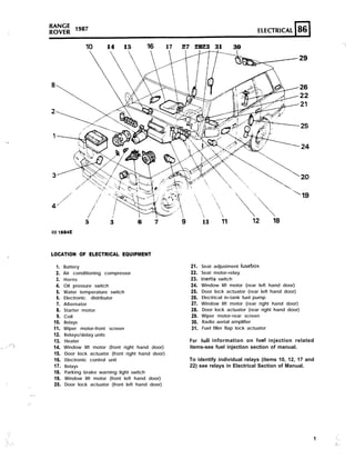
  • 1. :, ..:, ,..’ 3 : ’ . : .: .’ ‘.. ‘.‘., ‘. .’ _- . . . ,- 10 14 15 16 17 27 2823 31 30 5 3 6 7 RR 1884E LOCATION OF ELECTRICAL EQUIPMENT 1. 2. 3. 4. 5. 6. 7. 8. 9. 10. 11. 12. 13. 14. 15. 16. 17. 18. 19. 20. Battery Air conditioning compressor Horns Oil pressure switch Water temperature switch Electronic distributor Alternator Starter motor Coil Relays Wiper motor-front screen Relays/delay units Heater Window lift motor (front right hand door) Door lock actuator (front right hand door) Electronic control unit Relays Parking brake warning light switch Window lift motor (front left hand door) Door lock actuator (front left hand door) ‘,’ 13 ;1 21. 22. 23. 24. 25. 26. 27. 28. 29. 30. 31. Seat adjustment fusebox Seat motor-relay Inertia switch Window lift motor (rear left hand door) Door lock actuator (rear left hand door) Electrical in-tank fuel pump Window lift motor (rear right hand door) Door lock actuator (rear right hand door) Wiper motor-rear screen Radio aerial amplifier Fuel filler flap lock actuator For fuII information on fuel injection related items-see fuel injection section of manual. To identify individual relays (items 10, 12, 17 and 22) see relays in Electrical Section of Manual. 1 ..I, ::;..
  • 2. 1 9 8 7 KAN‘t R O V E R FAULT DIAGNOSIS SYMPTOM POSSIBLE CAUSE CURE i-Battery in low state of charge 1. Broken or loose connection in alternator circuit 2. Current voltage regulator not functioning correctly 3. Slip rings greasy or dirty. 4. Brushes worn, not fitted correctly or wrong type 5. Fan belt broken 1. Examine the charging and field circuit wiring. Tighten any loose connections, repair/replace broken leads. Examine the battery connection. 2. Check/fit new unit 3. Clean 4. Fit new brushes 5. Fit new belt B-Battery overcharging leading to burnt out bulbs and trequent need for topping-up 1. Current voltage regulator not functioning correctly 1. Fit new unit C-Lamps giving insufficient illumination I. Battery discharged 2. Bulbs discoloured through prolonged use 3. Fan belt broken I. Charge the battery from independent supply or by a long period of daylight running. 2. Fit new bulb 3. Fit new belt D-Lamps light when switched on but fade out 1. Battery discharged I. Charge the battery from an independent supply or by a long period of daylight running E-Lights flicker 1. Loose connection 1. Tighten/clean F-Failure of lights 1. Battery discharged 2. Loose broken connection 3. Fan belt broken I. Charge the battery from an independent supply or by a long period of daylight running 1. Locate and rectify 3. Fit new belt 2
  • 3. ,“.. , .._.. , . . ’ i, ,2.‘,‘.’ ‘, : .:, ‘, .’ , :: ‘; .: .’ ‘. : SYMPTOM POSSIBLE CAUSE CURE ;-Starter motor lacks power or fails to turn engine 1. Stiff engine 2. Battery discharged 3. Broken or loose connection in starter circuit 4. Greasy or drrty skp rings. 5. Brushes worn, not fitted correctly or wrong type 6. Brushes sticking in holders or incorrectly tensioned. 7. Starter pinion jammed in mesh with flywheel I. Locate cause and remedy 2. Charge the battery either by a long period of daytime running or from independent electrical supply 3. Check and tighten all battery, starter and starter switch connections and check the cables connecting these units for damage 4. Clean / 5. Fit new brushes 6 . Rectiiy 7. Remove starter motor and Investigate 1 H-Starter noisy 1. Starter pinion or flywheel teeth chipped or damaged 2. Starter motor loose on engine 3. Armature shaft bearing , 1. Fit new components 2. Rectify, checking pinion and the flywheel for damage 3. Fit new bearing I-Starter operates but does not crank the engine I. Pinion of starter does not engage with the flywheel 1. Check operation of starter solenoid. If correct, remove starter motor and investigate &Starter pinion will not disengage from the flywheel when the engine is running I. Starter pinion jammed in mesh with the flywheel 1. Remove starter motor and investigate 3
  • 4. 1:: X ...... ,::: ‘. .,.. : RANGE lg8’ ROVER SYMPTOM POSSIBLE CAUSE CURE .-Engine will not start 1. The starter will not turn the engine due to a discharged battery 2. The starter will not turn due to incorrect gear selection. 3. Sparking plugs faulty. dirty or incorrect plug gaps 4. Defective coil or distributor 5. A fault in the low tension wiring circuit 6. Faultv amplifier 7. Air gap out of adjustment 8. Fuel system fault 1. Recharge battery by running the car for a long period during daylight or from an independent electrical supply 2. Select ‘P’ or ‘N’ 3. Rectify’ fit new plugs I 4. gLv;; ign;t;ll checks. distributor 5. Examine all the ignition cables and check that the terminals are secure and not corroded. 6. Check/fit npw component if necessary. 7. Adjust 8. See Fuel System Section. M-Engine misfired stalls 1. Faulty sparking plugs 2. Air gap incorrectly set 3. Distributor cap cracked 4. Faulty pick-up or reluctor 5. Excessive wear in distributor shaft brushes, etc. 6. Rotor arm and flash shield cracked or showing signs of tracking 1. Rectify 2. Adjust 3. Fit new cap 4. Fit new components 5. Fit a new components 6. Fit new component _-.- 4
  • 5. ,..” ” ..’ ‘. SYMPTOM POSSIBLE CAUSE CURE &Frequent recharging of the battery necessary 1. Alternator inoperative 2. Loose or corroded connections 3. Slipping fan belt 4. Voltage regulator faulty 5. Excessive use of the starter motor 6. Vehicle operation confined largely to night driving 7. Abnormal accessory load 8. Internal discharge of the batten, 1. Check the brushes, cables and connections or fit a new alternator 2. Examine ail connections especially the battery terminals and ground cables 3. Adjust 4. Fit new component 5. 111 the hands of the operator, advise 6. In the hands of the operator, advise 7. Superfluous electrical fittings such as extra lamps, etc. 8. Fit new battery I ‘-Alternator not charging correctly 1. Slipping fan belt 2. Voltage control not operating correctly 3. Greasy, charred or glazed slip rings 4. Brushes worn, sticking or oily 5. Shorted, open or burnt -out field coils I . Adjust 2. Rectify/ fit new component 3. Clean 4. Rectify/fit new brushes 5. Fit new field coils 3-Alternator noisy 1. Worn, damaged or defective bearings 2. Cracked or damaged pulley 3. Alternator out of alignment 4. Alternator loose in mounting 5. Excessive brush noise I. Fit new bearings 2. Fit new pulley 3. Rectify 4. Rectify 5. Check for rough or dirty slip rings, badly seating brushes, incorrect brush tension, loose brushes and loose field magnets. Rectify/fit new components R-Poor performance of horns 1. Low voltage due to discharged battery 2. Bad connections in wiring 3. Loose mounting nut 4. A faulty horn 1. Recharge 2. Carefully inspect all connections and horn push 3. Rectify 4. Fit new horn
  • 6. ..:... ,. ,’ .’ ,;.:. .:... 1987 KANGE ROVER SYMPTOM POSSIBLE CAUSE CURE S-Central door locking does not operate (on all doors) 1. Battery discharged 2. Control unit in driver’s door lock actuator faulty 3. Loose or broken connection in driver’s door 4. Blown fuse 1. Recharge 2. Fit new unit 3. Locate and rectif) 4. Rectify T-Central door locking does not operate (on one door only) 1. Loose or broken connection 2. Lock actuator failure 3. Faulty lock 4. Mechanical linkages disconnected 1. Locate and rectii) 2. Fit new actuator 3. Rectify 4. Locate and rectify U-Window lift will not aperate 1. Motor failure 2. Loose or broken connection 3. Faulty switch 4. Mechanical linkage faulty 1. Fit new motor 2. Locate and rectifv 3. Fit new switch 4. Rectify V-Exterior mirrors fail to operate 1. Loose or broken connection 2. Faulty switch 3. Mirror motor failure I. Locate and rectify 2. Fit new switch 3. Fit new motor 6
  • 7. , ‘. .,..., . . . ,. .” ‘,.. PO;;; 1 9 8 7 4 ELECTRICAL 86 ; ELECTRICALEQUIPMENT DESCRIPTION The electrical system is Negative ground, and it is most important to ensure correct polarity of the electrical connections at all times. Any incorrect connections made when reconnecting cables may cause irreparable damage to the semi-conductor device? used in the alternator and regulator. Incorrect polarity would also seriously damage any transistorized equipment such as radio and tachometer etc. WARNING: During battery removal or before carrying out any repairs or maintenance to electrical components always disconnect the battery negative lead first. If the positive read is disconnected with the negative lead in place, accidental contact of the wrench to any grounded metal part could cause a severe spark, possibly resulting in personal injury. Upon installation of the battery the positive lead should be connected first. ALTERNATOR - LUCAS A13380 The alternator is a three phase, field sensed unit. The rotor and stator windings produce three phase alternating current, AC, which is rectified to direct current, DC. The electronic voltage regulator unit controls the alternator output voltage by high frequency switching of the rotor field circuit. Use only the correct Range Rover replacement fan belt. Occasionally check that the engine and alternator pulleys are accurately aligned. It is essential that good electrical connections are maintained at all times. Of particular importance are those in the charging circuit (including those at the battery) which should be occasionally inspected to see that they are clean and tight. In this way any significant increase in circuit resistance can be prevented. Do not disconnect battery cables while the engine is running or damage to the semi-conductor devices may occur. It is also inadvisable to break or make any connections in the alternator charging and control circuits while the engine is running. The Model 15TR electronic voltage regulator employs micro-circuit techniques resulting in improved performance under difficult service conditions. The whole assembly is encapsulated in silicone rubber and housed in an aluminium heat sink, ensuring complete protection against the adverse effects of temperature, dust. and moisture etc. < 1: The regulating voltage is set during manufacture to give the required regulating voltage range of 14.2 ;:I$ ‘, + 0.2 volts, and no adjustment is necessary. The only maintenance needed is the occasional check on terminal connections and wiping with a clean dry cloth. The alternatn: svstem provide< f o r d i r e c t connecuon OI a charge (ignition) indicator warning light, and eliminates the need for a field switching relay or warning light control unit. As the warning lamp is connected in the charging circuit, lamp failure will cause loss of charge. Lamp should be checked regularly and a spare carried. When using rapid charge equipment to re-charge the battery, the battery must be disconnected from the vehicle. REVISED: SEPT. 87 7 .: .’
  • 8. RANGE lg8’ R O V E R ALTERNATOR Remove and refit Removing ALTERNATOR DRIVE BELT - Adjust 1. Loosen the alternator fixings and the adjustment link. 1. Disconnect battery ground lead. 2. Pivot the alternator to give the required belt 2. Disconnect leads from alternator. tension. 3. Belt tension should be 4 to 6mm (0.19 to 0.25 in) at the point indicated by the bold arrow. 3. Loosen alternator fixings, pivot alternator inwards and remove drive belt. 4. Remove three mounting bolts and lift the alternator clear of the engine. 4. Tighten the alternator fixing bolts and the adjustment link. Refitting 5. Fit the alternator and mounting bolts. NOTE: Check adjustment after running engine at fast idle speed for 3 to 5 minutes if a new belt has been fitted. NOTE: The fan guard is attached to the front fixing and the adjustment bracket bolt. 6. Fit the drive belt and adjust the belt tension. 7. Tighten the mounting bolts and the adjustment bracket securing nut. 8. Connect the wiring leads tci the alternator. 9. Connect the battery. .- . REVISED: SEPT. 87
  • 9. : :. : ‘.,’ ., :,;.:: ,: . .I. .‘, . , ELECTRICAL 86l-l ALTERNATOR-LUCAS-TYPEA13380 1. Cover 2. Regulator 3. Rectifier 4. Drive end bracket 5. Bearing assembly ‘6. Rotor 7. Slip ring end bearing 8. Slip rings 9. Slip ring end bracket 10. Stator 11. Brush box 12. Brushes 13. Through bolts (three) 14. Suppressors REVISED: JULY 88 9
  • 10. . ., ALTERNATOR-LUCAS-TYPE A133/80 Overhaul Including Test (Bench) NOTE: Alternator charging circuit-The ignition warning light is connected in series with the alternator field circuit. Bulb failure would prevent the alternator charging, except at very high engine speeds, therefore, the bulb should be checked before suspecting an alternator failure. Precautions Battery polarity is NEGATIVE GROUND, which must be maintained at all times. No separate control unit is fitted; instead a voltage r e g u l a t o r o f micro-circuit construction is incorporated on the slip ring end bracket, inside the alternator cover. Batters voltage is apnlied to the alternator outout cable even when the ignrtron is swrtched off, the batteT must be disconnected before commencing any work on the alternator. The battery must also be disconnected when repairs to the body structure are being carried out using electric welding equipment. Sequence of connections RR1841E ? Suppression capacrtors (two) 2. Positrve suppression terminal 3. IND terminal 4. + output terminal 5. Sensing terminal ‘. ., ., .,:. 10 REVISED: JULY 88
  • 11. ALTERNATOR TESTING Charging system check 1. Check the battery is in good condition, with an open circuit voltage of at least 12.6 V. Recharge or fit a charged substitute battery to carry out test. 2. Check drive belt adjustment and condition. Rectify as necessary. 3. Check battery connections are clean and tight. 4. Check alternator connections are clean and tight. 5. Ensure that there is no continuous drain on b a t t e r y d u e , f o r e x a m p l e , t o i n t e r i o r , underhood or door edge lamps being left on. Alternator test The following instructions refer to the use of suitable test- equipment using a carbon pile rheostat. Testing-alternator removed 11. 12. 13. Withdraw the connectors from the alternator. Remove the alternator. Disconnect the suppressor and remove the alternator cover. 6. 7. 8. . : ..:;. 9. 10. C o n n e c t t e s t equrpment r e f e r r i n g t o t h e manufacturer’s instructions. Start engine and run at 3000 rev/min without accesory load. Rotate the carbon pile load control to achieve the greatest output (amps) without allowing voltage to fall below 12.0 V. A reading of 80 amps, minus 10% to allow for EFI and Ignition loss, should be obtained. Run engine at 3000 rev/min, switch selector to regulator test, read voltmeter. A reading of 13.6 to 14.4 V should be obtained. Switch selector to diode/stator test, switch on headlamps to load alternator. Raise engine speed to 3000 rev/min, read voltmeter. The needle must be within the IOK’ range. NOTE: See also charging circuit resistance test, page 13. 14. 15. 16. 17. 18. 19. 20. '1. Disconnect the lead and remove the rectifier assembly. Note the arrangement of the brush box connections and remove the screws securing the regulator to the brush box and withdraw. This screw also retains the inner brush mounting plate in position. Remove the screw retaining the outer brush box in position and withdraw both brushes. Check brushes for wear by measuring length o f b r u s h p r o t r u d i n g b e y o n d b r u s h b o x moulding. If length is 10mm (0.4 in) or less, fit new brushes. Check that brushes move freely in holders. If brush is sticking, clean with a mineral spirit moistened cloth or polish sides of brush with fine file. Check brush spring pressure using push-type spring gauge. Gauge should register 136 to 279s (5 to 10 oz) when brush is pulled back until face is flush with housing. If reading is outside these limits, fit a new brush assembly. Remove the two screws securing the brush box to the slip ring end bracket and lift off the brush box assembly. Securely clamp alternator in a vice and release t h e stator w i n d i n g c a b l e e n d s f r o m t h e rectifier bv applying a hot soldering iron to the terminal tags ot the rectifier. Pry out the cable ends when the solder melts. REVISED: SEPT. 87 11 :a
  • 12. .” ;:, ., .‘.’ : ” .,..y. ;:’ ‘. .I. :,, ‘. ; . ‘) i : ‘. :’ ..: j:; X 1987 &INCt ROVER 22. 23. Remove the two remaining screws securing the rectifier assembly to the slip ring end bracket and lift off the rectifier assembly. Further dismantling of the rectifier is not required. Check the diodes. C o n n e c t t h e t e s t equipment as shown and test each diode in turn, note whether lamp lights, then reverse test iead connections. The lamp should light in one direction only. Renew the rectifier assembly if a faulty diode is diagnosed. RR22BOE 24. 25. Remove the slip ring end bracket bolts and lift off the bracket. Connect a 12 volt battery and a 36 watt test lamp to two of the stator connections. Repeat the test replacing one of the two stator connections with the third. If test lamp fails to light in either test, fit a new stator. RR228i3E ’ 25’ 26. Using a 110 volt a.c. supply and a 15 watt test lamp, test for insulation between any one of t h e t h r e e stator c o n n e c t i o n s a n d stator laminations. If test lamp lights, fit a new stator. 27. 28. 29. 30. Clean surfaces of slip rings using a solvent moistened cloth. inspect slip ring surfaces tor signs of burning; remove burn mark< using vers fine sandpaper On no account should emery cloth or similar abrasives be used, or any attempt made to machine the slip rings. Note the position of the stator output leads in relation to the alternator fixing lugs, and lift the stator from the drive end bracket. Connect an ohmmeter to the slip rings. A reading of 2.6 ohms should be recorded. 31. Using a 110 volt a.c. supply and a 15 watt test lamp, test for insulation between one of the slip rings and one of the. rotor poles. If the test lamp lights, fit a new rotor. . : ,. ,. --... ;, : ‘. “,.._ 1 2 REVISED: SEPT. 87
  • 13. 32. To separate the drive end bracket and rotor, remove the shaft nut, washers, woodruff key and spacers from the shaft. 33. Remove bearing retaining plate by removing the three screws. Using a press, drive the rotor shaft from the drive end bearing. 34. ff necessary, to remove the slip rings or the slip ring end bearing on the rotor shaft, unsolder the outer slip ring connection and gently pry the slip ring off the shaft, repeat the procedure for the inner slip ring connection. Using a suitable extraction tool, withdraw the slrp ring bearing from the shaft. Reassembling 35. Reverse the dismantling procedure, noting the following points. (a) Use Shell Alvania ‘RA’ to lubricate bearings. (b) When refitting slip ring end bearing, ensure it is fitted with open side facing rotor. (c) Use Fry’s H.T.3 solder on slip ring field connections. (d) When refitting rotor to drive end bracket, support inner track of bearing. Do not use drive end bracket to support bearing when fitting rotor. (e) Tighten through-bolts evenly. (f) Fit brushes into housings before fitting brush moulding. (g) Tighten shaft nut to the correct torque, see Torque Values. (h) Refit regulator pack to brush moulding. 36. Reconnect the leads between the regulator, brush box and rectifier. 37. Refit the alternator. Testing in position Charging circuit resistance test. I. Connect a low range voltmeter between the alternator terminal marked + and the positive terminal of the battery. / RR2317t 2. Switch on the headlamps and start the engine. Set the throttle to run at approximately 3000 rev/min. Note the voltmeter reading. 3. Transfer the voltmeter connections to the frame of the alternator and the negative terminal of the battery, and again note the voltmeter reading. RR2318E 4. If the reading exceeds 0.5 volt on the positive side or 0.25 volt on the negative side, there is a high resistance in the charging circuit which must be traced and remedied. REVISED: SEPT. 87 13
  • 14. bl ELECTRICAL 1 9 8 7 K”d;i; BATTERY Remove and refit Remove and refit WARNING: During battery removal or before carrying out any repairs or maintenance to electrical components always disconnect the battery negative lead first. If the positive lead is disconnected with the negative lead in place, accidental contact of the wrench to any grounded metal part could cause a severe spark, possibly resulting in personal injury. Upon installation of the battery the positive lead should be connected iirst. HORNS Removing 1. Disconnect battery ground lead followed by the disconnection of the positive lead. 2. Release the four nuts securing the battery bracket in position. 3. Remove the bracket from the studs. 4 Remove- the batten, NOTE: Twin horns are f i t t e d . A n identification letter is stamped on the front outer rim of the horn; ‘HI-high note, IL’-low note. Removing 1. Disconnect the battery negative lead. 2. Remove radiator grille. 3. Remove the nut and withdraw the horn. 4. Disconnect the electrical leads. 5. Remove the plain and serrated washer. -------- RR669M - Refitting 5. Reverse the removal procedure. NOTE: Coat the battery clamps and terminals with petroleum jelly before refitting. Refitting NOTE: When refitting the horn ensure that the stud location is pushed firmly to the back of the elongated slot to prevent the horn fouling the radiator grille. 6. Reverse removal procedure. ” / REVISED: SEPT. 87
  • 15. 1 DISTRIBUTOR-LUCAS 35 DLMB SERVICE PARTS 1. 3. I 1 :: 6. 9. Cap HT brush and spring Rotor arm Insulation cover Pick-up module and base plate assembly Vacuum unit Amplifier module ‘0’~ring oil seal Gasket . . 2 3 4
  • 16. ,’ .” ’ : :. 1::. ,” .,.: :, I . . . , “.‘.;, ..‘. ....‘. L ELECTRONIC IGNITION A Lucas 35DLMB distributor is employed. This has a conventional vacuum advance unit and centrifugal automatic advance mechanism. A pick-up module, in conjunction with a rotating timing reluctor inside the distributor body, generates timing signals. These are applied to an electronic ignition amplifier module mounted on the side of the distributor body. NOTE: The pick-up air gap is fgctory set. Do not adjust the gap unless the pick-up IS being changed or the base plate has been moved. Use a non-ferrous feeler gauge to set the air gap. DISTRIBUFOR Remove and refit Removin,? 1. Disconnect the battery neghkive lead. 2. Disconnect the vacuum hose. 3. Remove the distributor cap. 4. Disconnect low tension lead from the coil. 5. Mark distributor body in relation to centre line of rotor arm. NOTE: Marking distributor enables refitting in exact original position, but if engine is turned w h i l e d i s t r i b u t o r i s r e m o v e d , complete ignition timing procedure must be followed. 7. Release the distributor clamp and remove the distributor. Refittin: NOTE: If a new distributor is being fitted, mark body in same relative position as distributor removed. 6. Add alignment marks to distributor and front cover. 8. Leads for distributor cap should be connected as illustrated. Figures I to 8 inclusive indicate plug lead numbers. RH-Right hand side of engine, when viewed from the rear. LH-Left hand side of engine, when viewed from the rear. 16
  • 17. , ELECTRICAL 86 9. If engine has not been turned while distributor has been removed, proceed as follows (items 10 to 17). Alternatively proceed to instruction 18. 10. Fit new ‘0’ ring seal to distributor housing. 11. Turn distributor drive until centre line of rotor arm is 30” counter- clockwise from mark made on top edge of distributor body. 12. Fit distributor in accordance with alignment markings. NOTE: It may be necessary to align oil pump drive shaft to enable distributor drive shaft to engage in slot. 13. Fit clamp and bolt. Secure distributor in exact original position. 14. Connect vacuum hose to distributor and low tension lead to coil. 15. Fit distributor cap. 16. Reconnect battery. 17. Using suitable electronic equipme II8, set the ignition timing, see IGNITION TIMING-Adjust. 18. If, with distributor removed, engine has been turned it will be necessary to carry out the following procedure. 19. Set engine-No. 1 piston to static ignition timing figure (see Engine Tuning Data- Section 05) on compression stroke. 20. Turn distributor drive until rotor arm is approximately 30” . counter-clockwise from number one sparking plug lead position on cap. 21. Fit distributor to engine. 22. Check that centre line of rotor arm is now in line with number one sparking plug lead on cap. Reposition distributor if necessary. 23. If distributor does not seat correctly in front cover, oil pump drive is not engaged. Engage by lightly pressing down distributor while turning engine. 24. Fit clamp and bolt leaving both loose at this stage. 25. Set the ignition timing statically to 6” B.T.D.C. 26. Connect the vacuum hose to the distributor. 27. Fit low tension lead to coil. 28. Fit drstributor cap. 29. Reconnect the battery. 30. Using suitable electronic equipment set the ignition timing, see IGNITION TIMING-Adjust. DISTRIBUTOR-LUCAS 35DLM8 Overhaul DISTRIBUTOR CAP 1. Unclip and remove the cap 2. Fit a new cap if known to be faulty. 3. Clean the cap and HT brush with a lint free cloth. REVISED: JUNE 87 ROTOR ARM 4. Pull rotor arm from shaft. 5. Fit a new rotor arm if known to be faulty. INSULATION COVER (Flash shield) 6. Remove cover, secured by three screws. 7. Fit a new cover if known to be faulty. VACUUM UNIT 8. Remove two screws from vacuum unit securing bracket, disengage vacuum unit connecting rod from pick-up base plate connecting peg, and withdraw vacuum unit from distributor body. Continued 17 ;
  • 18. 86 ELECTRICAL RANGE lg8’ ROVER AMPLIFIER MODULE FIlTlNC PICK-UP AND BASE PLATE ASSEMBLY 9. 10. 11. Remove two screws and withdraw the module. Remove the gasket. Remove two screws securing the cast heatsink and remove the heatsink. WARNING: The amplifier module is a sealed unit containing Beryllia. This substance is extremely dangerous if handled. Do not attempt to open or crush the module. PICK-UP AND BASE PLATE ASSEMBLY 12. 13. 14. 15. 16. Use circlip pliers to remove the circlip retaining the reluctor on rotor shaft. Remove the fiat washer and then the ‘0’ ring recessed in the top 01 the reluctor. Gently withdraw the reluctor from the shaft, taking care not to damage the teeth. NOTE: Coupling ring fitted beneath reluctor. Remove three support pillars and cable grommet. Lift out the pick-up and base plate assembly. NOTE: Do not disturb the two barrel nuts securing the pick-up module, otherwise the air gap will need re-adjustment. Fit a new pick-up and base plate assembly if module is known to be faulty, otherwise check pick-up winding resistance (2k-5k ohm). RE-ASSEMBLY 17. This is mainly a reversal of the dismantling procedure, noting the following points: LUBRICATION Apply clean engine oil: a. A spot into the rotor spindle before fitting rotor arm. Apply Omnilube 2 (or equivalent) grease. 18 REVISED: JUNE 87 b. Auto advance mechanism. :: Pick-up plate centre bearing. Pre tilt spring and its rubbing area (pick-up and base plate assembly). e. Vacuum unit connecting peg (pick-up and base plate assembly). f. The connecting peg hole in vacuum unit connecting rod. 18. Pick-up leads must be prevented from fouling the rotating reluctor. Both leads should be located in plastic guide as illustrated. Check during re-assembly. REFITTING RELUCTOR lo Slide reklctor a< fa:. ai ii Lvili go on rotor shafi then rotate reluctor- until it engages with the coupling ring beneath the pick-up base plate. The distributor shaft, coupling ring and reluctor are ‘keyed’ and rotate together. Fit the ‘0’ ring, flat washer and retaining circlip. PICK-UP AIR GAP ADjUSTMENT .. ., 20. The air gap between the pick-up limb and reluctor teeth must be set within the specified limits, using a non-ferrous feeler gauge. 21. If adjustment is necessary, slacken the two barrel nuts to set the air gap. See Engine Tuning Data. .... , 1 ., ‘, b
  • 19. ‘.. .: .- ELECTRICAL 86f - l NOTE: When the original pick-up and base plate assembly has been refitted the air gap should be checked, and adjusted if necessary. When fitting a new assembly the air gap will require adjusting to wittiin the specified limits. AMPLIFIER MODULE 22. Before fitting the module, apply MS4 Silicone grease or equivalent heat-conducting compound to the amplifier module backplate, the seating face on distributor body and both faces of the heatslnk casting. IGNITION COIL Remove and refit Removing I. Disconnect the battery negative terminal. 2. Disconnect the H@h Tension and Low Tension electrical leads from the Ignition coil. 3. Remove the two bolts securing the coil to the valance. NOTE: A ground strap is located under one of the bolts. 4. Remove the coil from the engine compartment. Refitting 5. Reverse the removal instructions. NOTE: Ensure that the bolting location for the ground strap is free from paint and grease. Coat the area around the bolt with Petroleum Jelly. IGNITION TIMING Adjust It is essential that the following procedures are adhered to. Inaccurate timing can lead to serious engine damage and additionally create failure to comply with emission regulations. If the engine is being checked in the vehicle, the air conditioning compressor must be disengaged. On initial engine build, or if the’ distributor has been dlsrurbed tor any reason, the ignition timin? muqt be set statlcallv to 6’ B T.D.C. (This sequence is to gwe only an approximation in order that the engine may be s t a r t e d ) O N N O A C C O U N T M U S T T H E E N G I N E B E STARTED BEFORE THIS OPERATION IS CARRIED OUT. Equipment required Calibrated Tachometer Stroboscopic lamp 3 4 5. 6. 7. Couple stroboscopic timing lamp and tachometer to engine following the manufacturer’s instructions. Disconnect the vacuum hose from the distributor. Start engine, with no load and not exceeding 3 , 0 0 0 rev/min r u n e n g i n e u n t i l n o r m a l operating temperature is reached. (Thermostat open). Check that the normal idling speed falls within the tolerance specified in the data section. Idle speed for timing purposes must not exceed 800 rev/min. With the distributor clamping bolt loosened turn distributor until the timing flash coincides with the timing pointer and the correct timing mark on the rim of the torsional vibration damper as shown in the engine tuning section. Continued REVISED: MAY 89 19
  • 20. 1987 RANGE ROVER 8. 9. 10. Retighten the distributor clamping bolt securely. Recheck timing in the event that retightening has disturbed the distributor position. Refit vacuum hose. Disconnect stroboscopic timing lamp and tachometer from engine. LUCAS CONSTANT ENERGY IGNITION SYSTEM 35DLMlbPRELIMINARY CHECKS Inspect battery cables and connections to ensure they are clean and tight. Check battery state of charge it in doubt as to its condition. Inspect all L.T. connections to ensure that they are clean and tight. Check the H.T. leads are correctly posltioned and not shorting to ground agaIns any enFine components. The wirinq harness and I n d i v i d u a l c a b l e s shoula b e hrmly tastened t o prevent chaffing. PICK-UP AIR CAP Check the air gap between pick-up limb and reluctor teeth, using a non-ferrous gauge, see ‘Engine Tuning Data’. NOTE: The gap is set initially at the factory and will only require adjusting if tampered with or when the pick-up module is replaced. TEST 1: H.T. Sparking Remove coil/distributor H.T. lead from distributor cover and hold approximately 6mm (0.25 in) from the engine block, using suitable insulated pliers. Switch the ignition ‘On’ and operate the starter. Regular sparking indicates fault in H.T. distribution, plugs, timing or fueliing, proceed to Test 6. If no spark or weak spark occurs proceed to Test 2. , Test 2: LT. Voltage Switch the ignition ‘On’ - engine stationary. (a) Connect voltmeter to points in the circuit indicated by VI to V4 and make a note of the voltage readings. (b) Compare voltapes obtained with the specitied values listed below: EXPECTED READINGS Vl v2 v3 v4 (c) (d) More than 12 volts. 1 volt maximum below volts at Vl. 1 volt maximum below volts at Vl. 0 volt - 0.1 volt. (e) If all readings are correct proceed to Test 3. Check incorrect reading(s) with chart to identify area of possible faults, i.e. faults listed under heading SUSPECT and rectify. If coil and amplifier is suspected, disconnect L.T. lead at coil, repeat V3. If voltage is still incorrect, fit new coil. If voltage is now correct, check L.T. lead, if satisfactory fit new amplifier. (0 If engine will not start proceed to Test 3. .._ . I 20 REVISED: MAY 89 :’
  • 21. , : “._ ., .:....;. .I ,:.. ,: .i :.: 1 1 2 3 4 SUSPECT ‘. L l . 1 DISCHARGED BAlTERY I L L * IGN. SWITCH AND/OR WIRING !* l L l COIL OR AMPLIFIER l * * H ) AMPLIFIER GROUND TEST 4: Pick-up Coil Resistance .:: KEY l Expected Voltage H Voltage higher than expected L Voltage lower than expected TEST 3: ‘.’ Amplifier Switching D TO DlSTkJTOR ‘Connect the voltmeter between battery positive ( + ve) terminal and H.T. coil negative (-ve) terminal, the voltmeter should register 0 volts. Switch the ignition ‘On’, the voltmeter should still register 0 volts. Crank the engine, the voltmeter reading should increase when cranking, in which case proceed to Test 5. .. * If there is no increase in voltage during cranking proceed to Test 4. Remove the amplifier. Connect the ohmmeter leads to the two pick-up terminals in the body of the distributor. The ohmmeter should register between 2k and Sk ohm if pick-up is satisfactory. If ohmmeter reading is correct, check all connections between pick-up and amplifier, if satisfactory, fit new amplifier. If the engine still does not start carry out Test 5. Change the pick-up if ohmmeter reading is incorrect. If the engine still does not start proceed to Test 5. Continued REVISED: MAY 89 21 i 1.
  • 22. 1987 RANGE ROVER TEST 5: TEST 6: Coil H.T. Sparking Rotor Arm Remove existing coil/distributor H.T. lead and fit test H.T. lead to coii tower. Using suitable insulated pliers, hold free end about 6mm (0.25 in) from the engine block and crank the engine. There should be good H.T. sparking. If weak or no sparkmp. fit new coil repeat test. H.T. sparking good, repeat test with original H.T. lead. If sparking is good carry out Test 6. If weak or no sparking, fit new H.T. lead, if engine will not start carry out Test 6. 2 2 Remove distributor cover. Disconnect coil H.T. lead from cover, using insulated pliers hold about 3mm (0.13 in) above rotor arm electrode and crank the engine. There should be no H.T. sparking between rotor and H.T lead. Ii satisfactorv canv out Test 7. If H.T. sparking occurs, an earth fault on rotor arm is indicated. Fit new rotor arm. If engine will not start carry out Test 7. TEST 7: Visual and H.T. Cable Checks Examine: 1. Distributor Cover 2. Coil Top 3. H.T. Cable Insulation 4. H.T. Cable Continuity 5. Sparking Plugs NOTE: 1. Reluctor 2. Rotor and Insulation Cover REVISED: MAY 89 Should be: i Clean, dry, no tracking marks Clean, dry, no tracking marks. Must not be cracked, chafed or perished Must not be open circuit Clean, dry, and set to correct gap Must not foul pick-up or leads Must not be cracked or show signs of tracking marks
  • 23. :: .-- : . .’ R”o”v’;;; 1987 ELECTRICAL I86 1 HEADLAMP ASSEMBLY/SEALED BEAM UNIT Remove and refit Removing 1. 2. 3. Disconnect the battery negative lead. Remove the radiator grille - see Body Section 76. Remove three crosshead screws and the headlamp retaining rim. 4. 5. 6. DO NOT disturb the two adjusting screws. Withdraw the sealed beam unit and disconnect the wiring plug from the rear of the unit. Remove three securing screws, pry away the grommet and withdraw the headlamp bowl. Refitting 7. Reverse removal procedure. HEADLAMP ALIGNMENT ; “’ Headlamp beam setting should only be carried out by qualified person using suitable beam setting equipment. 1. Turn the top adjusting screw counter-clockwise to lower the beam, clockwise to raise the beam. 2. Turn the side adjusting screw counter-clockwise to move the beam to the left, clockwise to move the beam to the right. .- _.: AUXILIARY DRIVING LAMP-RH AND LH Remove, refit and adjust Bulb replacement 1. -: &_ 3. 4. .- Disconnect the batten) negative lead. The auxiliary dnvlng lamp securing nut IS located beneath the front fender adjacent to the front body fixing. Access to the lamp is gained through the front wheel arch. Disconnect the electrical plug. Remove the single nut and washer. RR63BM 5. From the front of the vehicle, maneuver the lamp and remove it from the spoiler opening. 6. Remove the two screws securing the cover to the rear of the lamp. 7. Withdraw the cover. 8. Disconnect the lucar connector. 9. Release the spring clip securing the bulb to the lamp unit. 10. Remove the bulb. REVISED: jULY 88 2 3
  • 24. .,,.L ;.-. ,:: 1987 MNCIt ROVER Refitting 11. Fit a new bulb ensuring that the two notches on the bulb body locate with the registers on the lamp unit. 12. Reverse the removal procedure. Adjusting The correct adjustment is beam horizontal (parallel to the ground) and parallel to the vehicle axis. 13. 14. 15. Loosen the lamp adjusting bolt to lower or raise the beam. Loosen the lamp securing bolt to move the beam to left or right. Tighten fixing bolts to the correct torque, see Torque Values. SIDELIGHT AND FLASHER LAMP ASSEMBLY-RH AND LH AND BULB Remove and refit Removing 1. 2. 3. 4. 5. Open the hood and disconnect the battery negative lead. Remove the two screws and plain washers securing the lamp assemly. Lift the assembly away sufficiently to gain access to the rear of the lamp. Remove the waterproof cover. Depress the two retaining clips and withdraw the bulb holder. 24 . 6. Remove the required bulb. The direction indicator bulb is located in the upper section of the bulb holder, the side lamp bulbin the lower. 7. Disconnect the multi-plug to remove the complete assembly. Refitting 8. Reverse the removal procedure, ensuring the waterproof cover is located correctly. TAIL, STOP, REVERSE AND FLASHER LAMP ASSEMBLY-RH AND LH Remove and refit Removing 1. 2. 3. 4. 5. 6. 7. 8. . . Disconnect the battery negative lead. Remove the four lens retaining screws. Remove lens. Remove sealing rubber, if required. NOTE: To remove the sealing rubber complete it is necessary to remove the side marker lens. Remove the bulbs. Remove the four screws securing the lamp unit to the body. Remove the two through-screws from the reflector side, which also secure the lamp unit to the body. Ease the lamp unit forward and disconnect leads at moulded connectors. . ‘,’ ,,( REVISED: JULY 88 : .’ ‘. :
  • 25. ro;z; 1 9 8 7 E L E C T R I C A L 86 Refitting 9. Reverse the removal procedure. REFLECTORS/SIDE MARKER LAMPASSEMULI’ -Rtf AND LH BULB Remove and refit .’ ‘. ‘. Removing 1. Remove the four screws securing the lens. 2. Remove the lens. 3. Remove the bulb. i I - NOTE: To remove the rubber seal completely it is necessary to remove the tail light lens. Refitting _’ 4. Reverse the removal procedure. .i:.. UNDER HOOD LAMP ASSEMBLY Remove and refit Removing 1. Disconnect the battery negative lead. 2. Remove the two securing screws. 3. Remove the lamp glass. 4. Pull the five-watt ‘wedge’ type bulb from the bulb holder. .,’ I 2 R R483M e 5. 6. Disconnect the electrical leads located below the hood lamp switch attached to the inner fender. 1. Pull the rubber grommet off the leads and pull the lamp and leads up through the hood stiffener ‘channel. ‘. Refitting 7. Reverse operations NOTE: A piece of 1 to 6. bent wire will be needed . to pull the electrical leads out of the channel exit hole when fitting a new lamp assembly. REVISED: JULY 88 25 ;
  • 26. 86 ELECTRICAL 1 9 8 7 RANGE R O V E R ‘. HEATER/VENTltATlON AND AIR CONDITIONING CONTROL PANEL Bulb replacement The heater/ventilation control panel is illuminated by four 12-volt 1.2 watt ‘wedge’ type (capless) bulbs, In the event of a bulb failure a replacement bulb can be fitted as follows: 1. Pull the five finger tip knobs off the control levers. 2. Remove the two screws at the top of the panel. 3. Carefully ease the panel away from the centre console only as lar as the electrical leads will permit. 4. Pull the appropriate bulb holder out of the rear of the panel. 5. Pull the bulb from the holder. 6. Fit a new bulb and push the bulb holder firmly back into its location at the rear of the panel. -.._ ---.. -. Refitting 7. Ensuring that the electrical leads do not become trapped between the panel console and operating levers, refit the panel. 2 6 REVISED: JULY 88 DOOR EDGE LAMPS/PUDDLE LAMPS ..... Incorporated into the front door assemblies are door edge lamps and puddle lamps, these are located on the door edge and bottom of the door. The lamps are activated by the courtesy light switches when either front door is opened and will immediately switch off when both doors are closed. Remove and refit 1. 2. 3. 4. 5. 6. 7. 8. . Ensure the siae doot glass is fully closed. Disconnect the battery negatrve lead. Remove the interior door handle and arm rest/door pull from the door. Carefuliy release the interior door trim pad from the inner door panel. Peel back the lower half of the plastic vapour barrier. .- Disconnect the door edge lamp and puddle lamn two pin electrical plugs within the door. accessrbfe tnrough the lower centre and outer openings 01 the inner door panel. Release the door edge lamp electrical leads from the retaining clips. Remove the lens and pry the lamps out of the door and withdraw the electrical leads. , ’ Refitting 9. Reverse the removal procedure. NOTE: Ensure the door lamp wiring harness is securely clipped to the lower stiffener plate within the door to prevent damage occurring to the electrical leads when the door glass is in its lowest position. f:,
  • 27. ” ,’ ,...’ : .,,‘,/I ‘. ”; ., ::::.::. . .,. ., ‘. ‘.‘.‘.... : -- :‘.: .: ELECTRICAL 86l-l DOOR EDGE LAMPS/PUDDLE IAMPS Bulb replacement I. Disconnect the battery negative lead. 2. Carefully pry out the lamp lens. 3. Withdraw the lamp body from the door ONLY as far as the electrical leads will permit. 4. Pull the bulb from the holder. m-r 5. Fit a new the bulb and refit the lamp lens. 6. Push the lamp into the door. The correct bulb type is a 12-volt 5-watt capless. AUTOMATICGEARSELECTOR-PANEL ILLUMINATION Bulb replacement Refitting 1. 2. 3. 4. 5. 6. 7. Disconnect the battery negative lead. ’ Unclip the cover from the top of the gear selector knob. Remove the circlip retaining the detent button. Withdraw the detent button. Remove the lower circlip above the gear selector knob securing nut. Remove the securing nut. Withdraw the serrated washer. RR632M 8. 9. 10. 11. 12. Slide the selector knob off the shaft. I Carefully pry the inset panel out of the floor mounted console, complete with -selector illumination panel and ash tray. The two illumination bulbs are located on the reverse side of the illumination panel. Pull the appropriate bulb holder from its location. if necessary, to facilitate easier removal of the bulb holders, remove the four screws securing the illumination panel to the outer surround panel. 13. Pull the bulb from the holder. The correct bulb type is a 24-volt 5-watt ‘wedge’ base (capless). 14. Reverse the removal procedure ensuring that the electrical leads beneath the floor mounted console do NOT become trapped between mating surfaces. 15. To prevent damage to the gear selector knob on reassembly do NOT overtighten the retaining nut, see Torque Values. 27
  • 28. 1987 RANGE ROVER LICENSE PLATE LAMP ASSEMBLY AND BULB INTERIOR ROOF LAMPS Remove and refit Removing 1. Disconnect the battery negative lead. 2. Remove the two self-tapping screws and washers. 3. Detach the lamp assembly. 4. Disconnect the bulb holder and remove the bulb. NOTE: Carerully pull the electrical leads out of the bottom of the lower tailgate panel to reveal the snap connectors. 5. 6. 7. Disconnect the electrical connections located at the bottom of the lower tailgate. Remove the bulb holder. Carefully pull the electrical leads up through the inside of the lower tailgate panels. Refitting 8. Reverse the removal procedure. bulb ‘type’ is a 12-volt, 5 watt (capless). 28 The correct wedge base ‘: Remove and refit The interior roof lamps are operated automatically via the side door and tailgate courtesy switches or by an independent switch located on the auxiliary switch panel. Removing 1. 2. 3. 4. 5. Disconnect the battery negative lead. Remove the lens irom the courtesy lamp by pressing upward and turning it counter-clockwise. Withdraw bulb from spring clip holder. Remove screws securing lamp base to roof panel. Lower the lamp to reveal the cable snap connections. 6 Disconnect the electrical connections. Refitting 7. Reverse the removal procedure. INTERIOR ROOF LAMPS CIRCUIT DELAY Remove and refit The roof lamp circuit incorporates a delay function which is designed to allow the lamps to remain on for 12 to 18 seconds after either of the front doors are closed. ... NOTE; Switching on the ignition (with both doors closed) will immediately over-ride this feature, switching the interior lamps off. r.. ‘ ,:i ::
  • 29. Removing I. Disconnect the battery negative lead. 2. Remove the six screws securing the lower dash panel. 3. Lower the dash panel to gain access to the red delay unit attached to the steering column support bracket. 4. Remove the delay unit by pushing the unit up off its retaining bracket, to clear the steering column support bracket. 5. Pull the red multi-plug off the delay unit. Refitting 6. Reverse the removal operations. STARTER MOTOR-LUCAS M78R . . ‘, ::I.:... ‘. ‘.‘.:a:* Remove and refit Removing I. Place the vehicle on a suitabie horst. 2. Disconnect the battery negative lead. 3. Disconnect the leads from the solenoid and starter motor and remove the exhaust heat .,. shield. 4. Remove the two bolts securing motor to the flywheel housing. 5. Remove the starter motor from the vehicle. the starter underneath RRlrnlE Refitting 6. Reverse the removal procedure.
  • 30. STARTER MOTOR-Lucas M78R Overhaul D i s m a n t l i n g :. .’ 1. Remove the starter motor. 2. Remove the braid between the starter and the :::, : solenoid terminal. .: 3. Remove the solenoid fixing screws. 4. Withdraw the solenoid body. : : 5. Lift and remove the solenoid plunger. 6. Remove two nuts and two screws from the commutator end bracket. 7. Remove the commutator end bracket. 8. Remove the grommet from the yoke. 9. Lift the brushbox assembly clear of the armature. 5 10. 11. 12. 13. 14. 15. 16. 17. 18. 19. 20. 21. 22. Remove the brush springs. Unclip and remove the ground brushes. Remove the insulating plate. Withdraw the brushes and bus bar. Remove the armature from the yoke. Remove the yoke. Remove the intermediate bracket. Loosen and remove the through bolts from the drive end bracket. Remove the sun and planet gears. Push out the drive shaft sprocket assembly from the drive end bracket. Carefully tap the thrust collar from over the lump ring back towards the drive. Pry the snap ring from its locating groove. Remove the drive assembly from the drive shaft. . .: 30 . -.
  • 31. PO;:; 1 9 8 7 ELECTRICAL 86 i. i’ Inspecting Solenoid 23. Check the continuity and resistance value of windings by connecting an ohmmeter as shown. (a) .::: (a) Resistance value should be. 1.074 -c 0.035 ohms (W (b) Resistance value should be: 0.298 + 0.015 ohms If test results are unsatisfactory replace the solenoid. If results are correct proceed to 24. 24. C h e c k t h e c o n t a c t s b y c o n n e c t i n g a n ohmmeter as shown. Solenoid plunger removed, ohmmeter should read infinity. Solenoid plunger operated by hand, ohmmeter should read zero. If test results are unsatisfactory, replace the solenoid. If results are correct proceed to 25. 25. Check operation of spring for freedom of movemenl. Brush gear 26. Check brush brushes move brushes with required. springs and ensure that the freely in their holders. Clean the a solvent moistened cloth, if Brush length new, Dimension A is 9mm (0.354 in). Minimum brush length, Dimension B is 3.5mm (0.138 in). 31 :. ‘_ .’ .,:y <.I...>
  • 32. RANGE lg8’ ROVER Armature 27. Check the armature insulation using suitable test equipment. Connect the tester between any one commutator segment and the shaft. The method illustrated uses a 1 lOV, 15W test lamp. If the lamp illuminates the armature is faulty, and a replacement component is required. 31. Drive end/intermediate end bracket: press out the bush using a suitable press and mandrel. 32. Press the new bush in, ensuring that on the drive end bracket, the bush is flush with the casting. 33. Commutator end bracket; thread a 9116” Whitworth or suitable similar tap firmly into the bush. Extract the bush with the tap using a power press in reverse. NOTE: Soak new bushes in engine oil for thirty minutes before fitting. Reassembl) 34. Reverse the instructions 1 to 22. Smear the teeth and operating collar of the roller clutch with Shell Retinax ‘A’ grease. Smear the pivot lever of the drive assembly with Mobil 22 grease. Smear the drive shaft sun and planet ! gears with Rocol BRB1200 grease. 35. Tighten all the flxinps to the correct torque-see Torque Values. Rm927E - - 2 8 . I f n e c e s s a r y , t h e commutator may be machined, providing a finished surface can be obtained without reducing the diameter below 28.8mm (1.13 in), otherwise a new commutator must be fitted. Finish the surface with fine emery cloth. Do not undercut the insulation slots. Drive assembly 29. Test the roller clutch. The pinion should rotate in one direction only, independent of the clutch body. Replace the unit if unsatisfactory or if teeth are damaged or worn. Bearings 30. Fit new the bearing bushes if there is evidence of armature fouling magnets or if there is perceptible side play between the shaft and bush. 32 .
  • 33. : * FUSE BOX A2 A3I I A 4 A5 A6 I I !:, ‘: : I1 I 12 I 13 I 14 I 15 16 I 17 118 RR 1759E FUSE NO. COLOUR CODE FUSE VALUE CIRCUIT SERVED IGNITION KEY CONTROLLED MAIN FUSE PANEL ,- . 1 Brown fhwn tlrown 0rown Tan Tan Blue Yellow Whole 7 5 amp 7.5 amp 7.5 amp 7.5 amp 5 amp 5 amp RI-I headlamp low beam and power wash LH headlamp low beam RH headlamp high beam LH headlamp high beam RH parkmg Itights and instrument dlummation LH parktng hghts and radio illummatton Front wash/wper mo,ors Heahngian conditioning motor Heated rear screen AUX AUX IGN Mirror heaters IGN Audw warnmg untt. headlamp flash,door. hood and mternal lamps, radm. clock. horns. hazard such. key ‘IN’ swatch and ermssmn mamtenance reminder ‘.. 2 : ..’ 3 4 5 6 7 15 amp 20 am00 9 10 11 25 .smb 3 amp 15 amp VlOlel Blue Not used12 13 ‘., . .‘.‘..:: 14 15 16 17 10 19 20 - 15 amp Low coolant monitor. slop and reverse lamps, direction IGN indicators, mrtrumenfs. bulb check. low oil monitor. screen wash flud momlor, interior lamp delay unit and speed transducer Auxiliary feed trailer Auxiliary drwng lamps Rear wash/wpe motor Cigar ltghters (front and rear), gear selector illumination Fuel pump Central lockmg Window 1111s AUX IGN ICN AUX E&e 15 amp Blue 15 Red amp 10 amp Yellow 20 Red amp 10 amp Red 10 amp White 25 amp NOTE: Radio/Cassette combination. An in-line type 5 amp fuse is incorporated in the power inpul lead of the unit. AUXILIARY FUSE PANEL-(A) A l AZ A3 A4 A5 A6 Yellow Yellow Tan Violet Elr0Wl 20 amp 20 amp 5 amp 3 amp 7.5 amp Au condltlonmg Ian Aor condmonmg Ian Atr condmonmg compressor clutch Spare Electric mwror motors Cruise control IGN IGN ICN KIN IGN NOTE: Sunroof fuse is a 20 amp blade type fuse and is located on the side of the sunroof main relay. See pages 77-78 for relay location. .‘. ,: ‘:.; :,,A.:. REVISED: JULY 88 33
  • 34. rl86 ELECTRICAL 1987 RANCE ROVER RR1760E LH a:C- AUXILIARY FUSE BOX (B)-Located under the front left-hand seat FUSE COLOUR NO CODE 81 Green 82 Green 83 ____ 84 _-__ I35 Green 86 Green FUSE BOX-Main and Auxiliarv Remove and refit Removing 1. Disconnect the battery negative lead. 2. Remove the clip-on fuse box cover. 3. Remove the fuses from the main and auxiliary fuse boxes. 4. Remove the single screw securing the top auxiliary fuse box to the fuse box surround. 5. Unclip the opposite end of the fuse box. 6. Remove the two screws securing the main fuse box to the lower centre dash panel. 7. Withdraw the auxiliary fuse box surround. 8. Maneuver the main and auxiliary fuse box to enable them to be withdrawn through the fuse box opening. 9. Remove the leads from the fuse boxes, by inserting a small screwdriver into each fuse socket to depress the small retaining tab on the back of the lucar connections, withdraw the leads from the rear of the fuse box. FUSE CIRCUIT VALUE SERVED 30 amp 30 amp -___ -___ 30 amp 30 amp Seat recline Seat base Spare Spare Seat recline Seat base Refitting IO. Reverse the removal instructions ensuring that all leads are refitted to the correct fuse socket (refer to main circuit diagram). NOTE: When refitting the leads to the fuse box, the retaining tabs on the back of the lucar connectors must be in their raised position to prevent the leads being pushed out of the rear of the fuse box when the fuse is refitted. RELAYS-Identification incorporated in the vehicle electrical circuits are several relays, some of which are located behind the lower dash panel attached to the steering column support bracket. Relays are also located in the engine compartment attached to the closure panel. these relays are accessible having removed the black protective cover. The remaining relays are located beneath both front seats. . 3 4 REVISED: JULY 88
  • 35. ( :j::.,. :,.;g: R”;E; 1 9 8 7 ELECTRICAL 86i-l 1 2 3 4 5 6 7 Closure panel viewed from the engine Steering column mounted relays viewed with the compartment, with protective cover removed. lower dash panel removed. Relay 1. Headlamp wash timer unit 2. Heated rear window 3. Starter solenoid relay 4. Compressor clutch 5. Condenser fan 6. Air conditioning/heater 7. Stowage position 8. Rear wiper delay 9. ignition load relay 10. Front wiper delay 11. Flasher/Hazard unit 12. Voltage sensitive switch 13. Interior lamp delay 14. Auxiliary lamp relay 15. Seat adjustment relay 16. Main EFI relay 17. Fuel pump relay Circuit Diagram Item Number 17. Main circuit diagram 65. Main circuit diagram 6. Main circuit diagram 11. Air conditioning diagram 9. Air conditioning diagram 5. Air conditioning diagram Not used 139. Main circuit diagram 1. Main circuit diagram 14. Main circuit diagram 74. Main circuit diagram 71. Main circuit diagram 100. Main circuit diagram 87. Main circuit diagram 4. Seat adjustment diagram 22. EFI circuit diagram 21. EFI circuit diagram Colour Black Natural Natural Natural Natural Natural .---..- Black Black Red Blue Yellow Red Natural Natural Natural Natural ,’ 35
  • 36. f-l86 ELECTRICAL RANGE lg8’ ROVER RR1028E Seat adjustment relay located beneath the left hand front seat adjacent to fuse box (6). -- RmsOZE Main EFI (black terminal block) and fuel pump relays (blue terminal block) mounted beneath right hand front seat. NOTE: Refer to fuel injection section of manual for full information on E.F.I. relays. RElAYWMounted on the engine compartment closure panel). Remove and refit Removing 1. Lift the hood. 2. Disconnect the battery negative lead. 3. Remove the bolt securing the relay protective cover, located on the front of the engine compartment closure panel. 4. Remove the cover. 3c c-. 5. Pull the appropriate relay off its multi-plug. Refitting .-, ‘. ., . . .... 6. Reverse the removal procedure. RELAYS-(Mounted on the steering column support bracket) Remove and refit Removal. Disconnect the battery negative lead. Remove the six screws securing the lower fascia panel. Lower the dash panel, disconnect the electric leads from the dimming control switch and remove the fascia panel. Locate the appropriate relay on the relay mounting bracket, carefully pull the relay off the multi-plug. Refitting 5. Reverse the removal procedure. RELAYS-(Floor mounted beneath front seats) Remove and refit Removing I. Position seat to gain access to the required relay. 2. Disconnect the battery negative lead. 3. Carefully pull the relay off the multi-plug. Refitting _.,... ? ....... :: 4. Reverse the removal procedure.
  • 37. po;f; 1987 ELECTRICAL 86 ;. .‘. AUXILIARY SWITCH PANEL The auxiliary switch panel contains four ‘push-push’ type switches which incorporate integral symbols for identification. (The first and sixth switch openings are fitted with blank covers, which are removable, to facilitate the fitting of extra switches if required). The symbols are illuminated by two bulbs which become operational when the vehicle lights are on. The heated rear screen switch (5) is provided with an individual warning light, illuminated when the switch IS operated. ,I ..; ,- * : ‘. .‘.:.‘.:Q;, ~R1846E 1. Blank. 2. Auxiliary driving lamps. 3. Cruise control master switch. 4. Interior and tailgate lamps. 5. Heated rear screen. 6. Blank. AUXILIARY SWITCH PANEL Remove and refit Removing 1. Disconnect the battery negative lead. 2. Carefully pry the auxiliary switch panel surround away from the centre console. 3. Withdraw the switch panel as far as the electrical leads will permit. 4. Unclip the multi-plugs at the rear of the switches by depressing the retaining lugs. 5. Pull the plugs from the switches. 6. Remove the switch assembly complete. NOTE: If necessary each individual switch can now be removed as follows. 7. Depress the small retaining lugs on the top and bottom of the switch and push the switch(es) through the front of the switch surround. Refitting 8. Reverse the removal procedure. NOTE: To aid identification and location of multi-plug to switch, a coloured plastic tab is attached to each body which corresponds. with an appropriate coloured multi-plug. The switches if removed, should always be refitted in their original position. 7 3 7 ,:.:
  • 38. 86 ELECTRICAL 1987 RANCE ROVER ,.-. Auxiliary switch panel/heated rear screen warning light warning light Bulb replacement (switch 5) 1. Disconnect the battery negative lead. 2. Carefully pry the switch panel surround away from the centre console. 3. Unclip the multi-plug from the rear of the switch and disconnect the plug. I- _ . AR 628K 4. The warning light bulb is located in the multi-plug and is removed by pulling the bulb from its location. 5. Fit a new bulb and refit the multi-plug. 6. Press the auxiliary switch panel back into the centre console. The correct bulb type is an amber 12-volt 1.2.watt ‘wedge’ base (capless). Auxiliary switch panel illumination To replace either bulb The auxiliary panel green illumination bulbs are located in the interior lamp/heated rear screen and multi-plugs, each bulb is positioned in the centre of a group of four switches. 1. Disconnect the battery negative lead. 2. Carefully pry the switch panel surround away from the centre console to give access to the multi-plugs at the rear of the switches. RR 629M Unclip and pull the multi- plugs from the rear of the appropriate switch. Pull the green illumination bulb irom its location. Fit a new bulb and refit the multi-plug. Press the auxiliary panel surround ‘back into the centre console. The correct bulb type IS a li-volt 1.2-watt ‘wedge’ base (capless). ..- 38 : .’ ,:
  • 39. .::.. _- ‘.. ; , ELECTRICAL 86l-l STEERING COLUMN CONTROLS The steering column switch layout is as follows: LEFT HAND CONTROLS Lower switch-Main lighting switch Upper switch-High and low beam, direction indicators and horn. RIGHT HAND CONTROLS Lower switch - Rear screen programmed wash/wipe. Upper switch - Windscreen programmed wash/wipe. STEERING WHEEL Refitting The following operations for steering column controls show the steering wheel removed, this is for clarity only, and is not a necessary part of the procedure. tf steering wheel removal is required, refer to steering wheel remove and refit on page 21 Section 57 carefullv observing the spiral cassetre mstructrons. 7. If both sides of the shroud have been removed ensure that the plate on the steering column is correctly located in the slot in the shroud. 8. Reverse the removal procedure. MAIN LIGHTING SWITCH STEERING COLUMN SHROUD REAR SCREEN PROGRAMMED WASH WIPE SWITCH Certain operations within the electrical section necessitate removal of the steering column shroud. Unless removal of both sides of the shroud is required, remove ONLY the side necessary for access. Remove and refit Removing Remove and refit 1. Remove the steering column shroud from the required side. Removing 2. Disconnect cables at snap connectors. 3. Push the two spring clips locating the switch inwards and remove the switch from its mounting.1. 2. 3. 4. 5. 6. Disconnect the battery negative lead. Remove the lower dash panel. Disconnect the electrical connections to either the master lighting switch or the rear screen wash wipe switch. (Disconnect both if removing the complete shroud). Left hand shroud-remove three securing screws and remove the shroud over the indicator/high beam switch. Right hand shroud-remove three securing screws and remove the shroud over the windscreen wash wipe switch. To facilitate reassembly remove the screw s e c u r i n g t h e t w o h a l v e s o f t h e s h r o u d together from one side only. Refitting 4. Reverse the removal procedure. REVISED: APR. 88 39
  • 40. 1987 RANGE ROVER WINDSCREEN PROGRAMMED WASH WIPE SWITCH HIGH AND LOW BEAM, DIRECTION INDICATORS AND HORN SWITCH 4. Lighting, indicator and horn switch: release the two harness multi-plugs from the back of the switch and remove the switch assembly. Wiper and washer switch: release the harness multi-plug from the back of the switch and remove the switch assembly. Remove and refit Refitting Removing 5. Reverse the removal procedure. 1. Remove the steering column shroud from the required side. 2. Release the appropriate retaining clip and pull the fibre optic guide from the housing. 3. Depress the retainers at the top and bottom of the switch and pull combined switch assembly away from the steering column switch housing. RR2023E HAZARD WARNING SWITCH BULB REPLACEMENT Remove and refit Removing 1. Disconnect the battery negative lead. 2. Pull the hazard switch cover upwards and remove it to gain access to the bulb. 3. Remove the bulb by pulling it upwards. A ..-., piece of rubber tubing or adhesive tape ,. ; attached to the bulb may facilitate removal and refitting. Refitting 4. Locate the bulb in its holder and reverse instructions 1 to 3. The correct bulb is a 12V, 1.2 watt ‘wedge’ base (capless). ..-‘, ,J . 40 REVISED: APR. 88
  • 41. ,’ ‘.’ ‘:, ‘:. ,’ j: ,.,‘. ., .‘, 1. .,:: ,‘, ‘,.” :. . . . . .., : ,:::.,: :;,., *. ,‘.‘.~,‘.‘. ‘. ‘. . .‘. . .‘i.‘. .,.:.. .,.( *..,* COLUMN SWITCH ILLUMINATION BULB 1, REPLACEMENT ..;,.;.*.y Remove and refit Removing 1. Disconnect the battery negative lead. 2. Remove the left hand side steering column shroud. 3. Working behind the column switch housing twist the bulb holder through 90” and withdraw. 4. Remove the bulb. __,,. .1 .I ..<.. RFX2037E ‘, Refitting 5. Reverse the removal procedure. The correct bulb type is a 12-volt, 1.2-watt ‘wedge’ base (capless). IGNITION STARTER SWITCH Remove and refit Removing 1. Disconnect the battery negative lead. 2. Remove the lower dash panel. 3. Remove the steering column shroud left hand side. 4. Disconnect the ignition switch cable at the multi-plug. 5. Remove the rubber cover protecting the switch. _. ,, “ RR1966E 6. Remove the single screw securing the ignrtion/starter switch to the housing. 7. Withdraw the switch. Refitting &. Reverse the removal procedure. DOOR PILLAR SWITCH Remove and refit Removing 1. 2. 3. 4. Disconnect the battery negative lead. Remove the screw securing the switch to door pillar. Withdraw switch. Disconnect electrical lead from connector blade. J I iIiI i RR2112E Refitting 5. Reverse removal procedure. REVISED: APR. 88 41 :. . . . i ‘* ..,’ ..:..
  • 42. .’ 1:. : ‘.‘, 1: :’ : ,: ... ... .’ ,;, .:’ ‘.. .‘., :,. ,. . ..” 86 ELECTRICAL RANGE “*’ ROVER REAR TAILGATE SWITCH Remove and refit Removing 1. 2. 3. 4. Disconnect the battery negative lead. Remove the single screw securing the switch to the tailgate opening. Withdraw the switch. Disconnect the electrical lead. Refitting 5. Reverse the removal procedure. UNDER HOOD ILLUMINATION SWITCH Remove and refit Removing 1. 2. 3. 4. Disconnect the battery negative lead. Remove the single screw securing the switch to the cowl panel. Withdraw the switch. Disconnect the electrical lead. RR49QM . . 42 REVISED: APR. 88 Refitting 5. Reverse the removal procedure. CIGAR LIGHTER-radio housing Remove and refit Removing 1. 2. 3. 4. 5. 6. Disconnect the battery negative lead. Remove the High/Low range gear knob. Remove the main gearbox knob. See Automatic gear selector panel illumination. Remove the glove box liner and release the parking brake cable from the parking brake lever, pry the inset panel out of the floor mounted console. Pull the two illumination bulbs from the selector panel. Release the glove box from its four floor mounted fixings. Raise the front of the glove box and console assemble and easp the unit away from the radro houslng. . ‘, ;,._ ,..:.
  • 43. :... &;;; 1987 ELECTRICAL 86 7. 8. 9. 10. 11. 12. 13. Remove the radio, referring to the Manufacturer’s instructions for removal and installation. Remove the single screw securing the housing to the top of the gearbox tunnel. Pull the housing away from the lower dash panel. Disconnect the electrical leads at the rear of the cigar lighter. Remove the push in switch from the lighter outer body. Depress the outer plastic surround where denoted by the arrows and push the outer body through the surround. Maneuver the plastic surround and remove it from the radio housing. !I’ 1p 12 ,&- g12 /.:5' !' RR2117E CIGAR LIGHTER ILLUMINATION -Bulb replacement 14. Remove the bulb holder from the plastic surround. 15. Pull the bulb from the holder. The correct b u l b t y p e i s a l2V 1.2-watt w e d g e b a s e (capless). . . RR2118E Refitting 16. Reverse the removal procedure. CIGAR LIGHTER-Glove Box The rear cigar lighter is located in the bottom of the glove box, access to the rear of the lighter is gained through heater/air vent duct below the rear ashtray. Follow instructions 13 to 16 of CIGAR LIGHTER - radio housing, to remove the lighter from the glove box. REVERSE LIGHT SWITCH-START INHIBITOR SWITCH/NEUTRAL SAFETY SWITCH Automatic gearbox Remove and refit The reverse light swatch is an integral part of the start rnhibrtor switch and is located on the left hand side OI tne gearbox above the tront ot the gearbox sump and is accessible from beneath the vehicle. Removing 1. Drive the vehicle onto a suitable hoist. 2. Disconnect the battery negative lead. 3. Disconnect the multi-plug. 4. Release the clamp bolt and remove the clamp. 5. Withdraw the switch from its location. RR626M I REVISED: APR. 88 43 .’‘.‘. . . . . : _‘,
  • 44. .‘,’ ,, .:, ‘. , : : .’ ,,: ‘. ‘,:,I ‘.‘,’ ‘, .,.: :, ‘. .. 5 ‘.) a.. .?. 5, ‘. . . ,.’ 1987 MNbt ROVER Refitting 6. Reverse the removal instructions. 7. Fit a NEW ‘0’ ring to the switch. OIL PRESSURE WARNING SWITCH Remove and refit Removing 1. Disconnect the battery negative lead. 2. Disconnect the electrical lead from the switch. 3. Unscrew the switch unit. 4. Remove switch and sealing washer. RR513M Refitting 5. Reverse the removal procedure, using a NEW sealing washer. COOLANT TEMPERATURE TRANSMlllER Remove and refit Removing 1. Disconnect the battery negative lead. 2. Disconnect the electrical lead from the transmitter. 3. Remove the transmitter from the inlet manifold. Refitting 4. Reverse the removal procedure, using a NEW sealing washer. STOP LIGHT SWITCH Remove and refil Removing 1. Disconnect the battery negative lead. 2. Remove the lower dash panel. 3. Depress the foot brake. 4. Remove the rubber protector from switch (where fitted). 5. Remove the hexagon nut. 6. Withdraw the switch. 7. Disconnect the electrical leads. . ‘: Refitting 8. Reverse the removal procedure. 44 REVISED: APR. 88 -.* . . :. . ‘:, :. . ,,..:
  • 45. ,: ,- :/.T‘:.. I ‘....: : PARKING BRAKE WARNING SWITCH Remove and refit Removing 1. 2. 3. 4. 5. 6. 7. a Disconnect the battery negative lead. Apply the parking brake. To gain access to the warning switch located on the side of the parking brake mounting bracket, it is necessary to remove the glove box liner. Remove the four screws securing the glove box liner and litt out the liner. Carefully pull the rear warm air flow hose away from the side of the parking brake mounting bracket to give access to the two screws securing the switch in position. Remove the two screws. Maneuver the switch around the front of the parking brake mounting bracket and disconnect the electrical lead. Withdraw the switch. Refitting 9. Reverse the removal procedure. EXTERIOR DRIVING MIRRORS 1. The mirror housing is hinged vertically and should be set in one of the two fixed angle positions provided to suit the respective left or right side mirror location. 2. Additionally, for safety and convenience, the mirror housing is designed to fold completely forwards or rearwards against the vehicle body. Adjusting 3. Fine adjustment is controlled by an electric motor inside the mirror housing. This is operated by two controls fitted in the dash panel. To adjust, select left or right hand mirror. Move the head of the finger tip control to the left, right. up or down as required. 4. The mirror also incorporates a demist facility, activated by operation of the rear window demist switch. 6 RRlQliE Replacing the mirror glass 5. Press the inner (wider) end of the glass inwards to its full extent. 6. Insert the fingers under the outer (narrower) end of the glass, and pull outwards until the glass is released from its four retaining clips. 7. Disconnect the two demister leads attached to the back of the glass unit. 8. To replace the glass, locate the inner (wider) end of the glass in the mirror housing first. Continued REVISED: APR. 88 ,45
  • 46. .: :. “. ‘. ,’ ‘.‘. ‘. ‘. . ‘1, : ; ;’ ‘: .::’ :; .” ‘. RANGE lg8’ ROVER 6 3 RR2038E - 9. 10. Carefully press the outer (narrower) end of the glass Inwards until it is salely held by its four retaining clips. Reset the fine adjustment as required. EXTERIOR DRIVING MIRRORS ELECTRIC MOTORS Remove and refit Removing 71. Disconnect the battery negative lead. 12. Remove the mirror glass, as described in items 5 to 7. 13. Remove the four self-tapping screws securing the motor assembly to the mirror body. 14. Maneuver the motor assembly to reveal the electrical connections on the rear of the motor. 15. Pull the leads from the rear of the motor assembly. Refitting 16. Reverse operations 11 to 15, ensuring that the electrical leads are correctly refitted (see electric mirror, circuit diagram). EXTERIOR DRIVING MIRRORS CONTROL SWITCHES Remove and refit 17. 18. 19. 2? Disconnect the battery negative lead. Carefully pry the switch retaining panel out of the dash panel. Withdraw the panel only as far as the electrical leads will permit. 20. Pull the multi-plug from the rear of the fingertip controlled mirror switch. 21. Disconnect the multi-plug at the rear of the selector switch and remove the panel. 22. Carefully p’y off the fingertip button at the operating end of the switch. 23. Unscrew the black plastic retaining collar securing the switch. 24. Remove the switch from the panel noting the position of the locating hole in the panel retaining clip 25. Depress the two spring clips securing the selector switch and push it through the panel. Refitting 26. Reverse operations 17 to 25. 46 REVISED: APR. 66
  • 47. I..>,% ‘.. ,: /j ._,..’ : ‘( ,.: .’ ‘. ; .‘:’ : ., ,. ‘,.’ ..: :’ : : . . ‘. ,.. ). : .,: ‘..A ./ : .,.....I.::...:., ‘... -. :’ ,..-. : /‘- k ,/ .‘. i :, ‘. EXTERIOR DRIVING MIRRORS COMPLETE ASSEMBLY Remove and refit Removing 27. 28. 29. 30. 31. 32. Disconnect the battery negative lead. Carefully pry off the interior finisher plate to reveal the three securing screws and electric wiring. Disconnect the two electrical plugs (one two pin. one three pin). Supporting the exterior mirror assembly remove the three securing screws (with plain and spring washer). Pull the inner mounting plate away from the inner door frame complete with the two retaining clips. Detach the mirror assembly from the outer door frame. 33. Remove the sealing rubber. CLOCK Remove and refit Removing 1. Disconnect the battery negative terminal. 2. Carefully pry the clock out of the dash panel to reveal the electrical connections. 3. 4. Disconnect the two electrical leads. Remove the illumination lead complete with holder and bulb. NOTE: The clock is illuminated by a 2.watt bayonet type bulb. Refitting 5. Reverse the removal procedure. Refitting 34. Reverse the operations 27 to 33. NOTE: To prevent damage to the electrical wiring do not push the leads down inside the door casing. REVISED: SEPT. 87 47 : : ‘,..‘..
  • 48. RANGE lg8’ ROVER INSTRUMENT BINNACLE WARNING LIGHT SYMBOLS Trailer connected-flashes with direction indicators (green) Direction indicator- left turn / right turn (green) Seat belt (red) Headlamp high beam on (blue) Engine oil pressure, low (red) Flashing - engine oil level low Electronic tuel injectlon warning lamp (red) indicates failure of air flow sensor, throttle potentiometer, water temperature thermistor, or Lambda sensor Ignition on/No charge indicator (red) Low coolant (red) Symbol (not used) will illuminate on initial bulb check Brake pad wear (amber) Brake fluid pressure failure, AP system/Brake fluid level, Lucas Girlinp system/Transmission park brake on (red) Automatic gearbox oil temperature high (red) Fuel indicator, low (amber) Low wash fluid (amber) REVISED: SEPT. 87
  • 49. ~o;~~ 1 9 8 7 ELECTRICAL 86 -. The differential lock warning light, (located on the ;’ , radio console) and the fifteen segments of the warning light panel within the binnacle will all be illuminated when the ignition key is turned to the ‘ignition On II’ position as an initial check to ensure that all bulbs are operational. All bulbs, except for the ‘Brake Failure/ Transmission Parking Brake’-‘Engine Oil Pressure’ and ‘Ignition On’ symbols will go out automatically. The ‘Engine Oil Pressure’ and ‘Ignition On’ symbols will remain on when the ignition key is turned to the engine crank position ‘III’ and extinguished when the engine IS running. The ‘Brake Failurefiransmission Parking Brake’ symbol will extinguish when the parking brake lever is released. NOTE: Should the ignition key be turned directly to the engine crank position the bulb check procedure will be overridden. _ ., .., ; ‘, ‘* . A pnoto rransrstor incorporated into the Instrument binnacle senses ambient light levels. During normal ambient daylight levels the warning light panel will glow at normal intensity. When ambient light levels decrease, the photo transistor senses the reduction and lowers the intensity of the warning light panel accordingly. PANEL AND WARNING LIGHT-bulb replacement 1. Disconnect the battery negative terminal. 2. Unclip the back of the cowl from the instrument binnacle to give access to the panel and warning light bulbs in the back of the instrument case. 1. Disconnect the battery negative terminal. 2. Remove the lower dash panel by releasing the six retaining screws. 3. Remove the four nuts (with spring and plain washers) from under the top dash rail which secure the instrument binnacle to the vehicle. 4. Unclip the binnacle cowl, from the rear, to provide access to the speedometer cable. 5. Disconnect the speedometer cable from the speedometer drive on the back of the instrument case. 3. Remove the appropriate bulb holder unit by 6. Remove the two large multi-plugs from the rotating it counter-clockwise and withdrawing printed circuit, and the single plug from the it. warning lamp control unit. NOTE: The “No Charge/Ignition On” warning light, identified by its-red coloured bulb holder, is of a higher wattage and is the only bulb which can be pulled from its holder and replaced independently. 4. Fit a new bulb holder unit and rotate clockwise to lock in position. The correct bulb type is a 1.2 watt bulb/holder unit, except the ignition bulb which is 2 watt wedge base type. 5. Refit the cowl and reconnect the battery. NOTE: if difficulty is experienced in changing bulbs, due to the limited space available the instrument binnacle fixings should be removed to enable the binnacle to be raised above the dash as far as other connections permit. See ‘Instrument Binnacle Removal’ below for details of binnacle mounting bracket fixing. INSTRUMENT BINNACLE Remove and refit Remove 1: REVISED: APR. 88
  • 50. 1987 RANGE ROVER / fwt809E 7. Lift the instrument binnacle from the top dash rail and transfer it to the workbench. Refitting L. keversr Removing instrument pack 9. IO. 11. Having removed the instrument binnacle from the vehicle, detach the binnacle mounting bracket. This is secured to the instrument case by two screws and to the bottom of the binnacle bezel by two smaller screws. Remove the two screws retaining the top of the bezel to the front housing and detach the bezel. Separate the instrument case from the binnacle housing by releasing the two wire clips. 12. Detach the curved lens from the binnacle housing by releasing the wire clip at the top. Refitting instrument pack to binnacle 13. Reverse removal instructions 9 to 12. Removing printed circuit, multi-function unit and photo transistor NOTE: Ensure all warning light and panel illumination bulb holders are removed before removing the printed circuit. Note the position of the no charge warning light (red holder). 14. Remove the two tachometer nuts (with washers) to release the printed circuit connecting tags. 15. Remove the four nuts (with washers) securing the fuel and temperature gauges to release the printed circuit from the fixing studs. 16. 17. 18. 19. Release the Wo retaining screws and carefully remove the multi-function unit. Using a pair of tweezers or a fine screwdriver, lift the printed circuit out of its location and extract the rubber contact pad. NOTE: If fitting a new multi-function unit the new rubber contact pad supplied MUST be installed under the printed circuit to ensure correct contact pressure. Remove the two harness connectors, retained by four screws. to release the printed circuit tags. Twist the photo transistor counter clockwise to drsengage from the binnacle housing. Remove the five screws securing the single multi-plug wiring connections. Note the position of the leads for reassembly. Carefully ease the printed circuit from its four locating pegs. Refittine the printed circuit, multi-function unit and photo transistor 20. Reverse the removal procedure items 14 to 19. 21. Ensure that the fuel and temperature gauge mounting studs are correctly located before pressing the printed circut on to its four locating pegs. Removing tachometer 22. 23. 24. 50 . REVISED: APR. 88 Carefully pry the needle shroud from the tachometer and disconnect the fibre optic element underneath the shroud. Remove the two nuts (with washers) at the back of the instrument case which retains the tachometer and release the printed circuit tags. Loosen the four nuts retaining the fuel and temperature gauges and carefully maneuver the tachometer from the front of the instrument case. Continued . . .I I
  • 51. RR 2271E _. instrument Pack 1. Fuel gauge 2. Temperature gauge 3. Voltage stabiliser 4. Ignition warning bulb (with separate red holder unit) 5. Panel/warning lights bulb/holder 6. Printed circuit input tags (for harness connection) 7. Speedometer drive unit 8. Printed circuit 9. 10. 11. 12. 1-i Tachometer Warning lights panel. instrument case (front) Curved lens Wire connecting clips Binnacle housing .-. 14. I 5. Speedometer 16. Photo transistor - automatic dimming - warning lights REVISED: APR. 88 :. ‘/ : 5 1 ,: ...
  • 52. 1861 ELECTRICAL 1987 KANC;t ROVER . . Instrument case (back) 1. Locating pegs 2. Panel light bulbs 3. Speedometer securing screw 4. Speedometer drive securing screws 5. Harness connectors 6. Warning light bulbs (14) 7. No charge warning light bulb (red holder) 8. Temperature and fuel gauge unit securing nuts PRINTED CIRCUIT HARNESS CONNECTIONS ~132251~ 20 1918 17 16 15 14 13 12 il 9. 10. 11. 12. 13. 14. 15. 16. Tachometer securing nuts Multi-function unit Printed circuit Pull-up resistor-high temperature gearbox oil Photo transistor Single multi-plug Single multi-plug securing screw Single multi-plug wiring connecting screws (5) lhhj 7 6 5 4 3 2 1 Sequence of connections looking towards the back of instrument case. 5 2 REVISED: APR. 88
  • 53. ro;f; 1987 ELECTRICAL 86 ” ;. :;., ‘. ,‘.‘.‘.’ ‘.‘.‘.‘i 1:. ‘,. ‘.‘,, ,’ :. CIRCUIT SERVED Tacho signal ........................................................... 1 lgnition switch 12~ + ............................................. 2 Low coolant input .................................................. 3 Ground-VE .............................................................. 4 Ignition warning light ............................................. 5 Low oil level/pressure warning light ....................... 6 High beam warning light ........................................ 7 Ground from bulb check unit ................................. B Trailer warning light ................................................ 9 Direction indicators warning light ......................... 10 Seat belts warning light ........................................ 11 E.F.I. warning light ................................................ 12 Temperature warmng light (automatic gearbox) ............................................. 13 Low wash fluid warning light ................................ 14 Not used .............................................................. 15 12V+ from bulb check unit ................................. 16 Brake fail warning light ......................................... 17 Panel illumination bulbs (6 off) ............................. 18 Low fuel warning light .......................................... 19 Low coolant warning light .................................... 20 NOTE: The following 21 to 25 are connected at the single multiplug located behind the binnacle Brake pad wearwarning light ............................... 21 ‘P’ symbol (initial bulb check only) ....................... 22 Fuel tank unit and fuel gauge ............................... 23 Temperature gauge .............................................. 24 Photo transistor .................................................... 25 22 / 23 2-q21 +?L -25 RR1762E 24 Sequence of pin connections viewed on the binnacle harness plug. ll- m -w 16 - 14- m w i m A I 2f-#5 :I m Rd2252E MULTI-FUNCTION UNIT A. 12v + supply B. Input to low coolant circuit C. Tachometer drive D. Tachometer E. Spare F. 1 OV + stabilised c. Input to fuel tank unit - stabilised H. Tachometer signal I. Low fuel warning light I. Spare K. Low coolant warning light L. Ground REVISED: MARCH 90 53 _ .y;: :
  • 54. I 86 ELECTRICAL RANGE “*’ ROVER Refitting the tachometer 25. Reverse the removal procedure, items 22 to 24. Removing fuel and temperature gauge unit 26. Carefully pry the needle shroud from the tachometer and disconnect the fibre optic element underneath the shroud. 27. Remove the two nuts (with washers) retaining the tachometer and release the printed circuit taps. 2b. Remove the four nuts (with washers) retaining the fuel and temperature gauges and carefully maneuver the tachometer, fuel and temperature gauge unit from the front of the instrument case. Refitting the fuel and temperature gauges 29. 30. 31. 32. Locate the fuel and temperature gauge unit in the instrument panel but do not fit thp washers and nuts at this stage. Feed the fibre optic element through the opening in the tachometer then locate the tachometer in the instrument panel. Position :he printed circuit tags over the two tachometer studs, fit the washers and fit and tighten the retaining nuts. Fit the washers to the four fuel and temperature gauge studs and fit and tighten the retaining nuts. Removing the speedometer and speedometer drive unit 33. 34. 54 Carefully pry the needle shroud from the element underneath the shroud. Remove the two hexagonal headed screws (with washers) at the back of the instrument case which retain the speedometer. .RRl e@dE Refitting 6. Reverse the removal procedure ensuring that the multi-plugs and unit are securely pushed into position. REVISED: MARCH 90 35. Carefully remove the speedometer from the front of the instrument case. ‘,,, 36. To release the speedometer drive unit, remove the two self-tapping screws securing it to the back of the instrument case. Refitting the speedometer and speedometer drive unit 37. Reverse the removal procedure items 33 to 36. WARNING LAMP CONTROL UNIT -see also page 69 Remove and refit Removing Disconnect the battery negative terminal. Release the six screws securing the lower dash panel below the steering column. Lower the dash panel and disconnect the multi-piug trom the rheostat switch. Pull the warning lamp control unit from the spring clip on the underside of the dash panel and disconnect the three multi-plugs from the unit. Remove the warning lamp control unit from the vehicle.
  • 55. . ‘. ‘_ .’ ‘, ‘.. ‘. . .., ‘, INSTRUMENT lLLUMlNATlON ELECTRONIC DIMMING CONTROURHEOSTAT The electronic dimming control switch is located on the lower dash panel adjacent to the steering column. Rotate the control upwards to fully illuminate the instruments and downwards to reduce intensity. The dimming control unit also controls the clock, heater and cigar lighter illumination. Remove and refit Removing 1. Disconnect the battery. 2. Remove the lower dash panel by releasing the six securing screws. 3. Disconnect the dimming control multi-plug. 4. Remove the two screws securing the dimmer control switch to the under-side of the lower dash panel. Reiitting Reverse operations 1 to 4. SPEEDOMETER CABLE Remove and refit Removing 1. 2. 3. 4. 5. Disconnect the battery negative lead. Remove the lower dash panel (beneath the steering column) by releasing six retaining screws. Unclip the back of the cowl from the instrument binnacle to give access to the speedometer drive. Disconnect the cable from the speedometer drive. Withdraw the cable and grommet through the bulkhead. 6. Working underneath the vehicle, disconnect the cable at the speed transducer. 7. Release the cable from the retaining clips. 8. To remove the shorter cable, disconnect it from the speed transducer and remove the single nut and clamp securing the cable to the speedometer drive housing at the rear of the transfer box. Refitting 9. Reverse instructions 1 to 8. WINDOW LIFT SWITCHES Remove and refit Removing I. Disconnect the battery negative lead. 2. Carefully pry the window lift switch surround away from the front of the glove box. 3. Disconnect. the multi-plug at the rear of the switchces). 4. Apply pressure to the rear of the switch to push i! thrauyh the surround. Refitting 5. Reverse the removal procedure. 55 :. ,:. I ‘. ‘., ‘,.’ . . ”
  • 56. 86 ELECTRICAL RANGE lg8’ R O V E R .- WINDOW LIFT MOTOR-Front doors Remove and refit Removing 1. 2. 3. 4. 5. 6. 7I 8. 9. 10. 11 56 Ensure that the side door glass is /n its fully closed position and secure it with adhesive tape. Disconnect the battery. Detach the arm-rest/door-pull finisher to reveal the two securing screws. Remove the two screws (with plain washers) to enable the arm-rest/door-pull to be detached from the inner door panel. Remove the interior door handle finisher button to reveal the screw retaining the h a n d l e s u r r o u n d . Remove the screw and detach the handle surround from the inner door panel. Detach the inner door trim pad by inserting a screwdriver between the trim pad and inner door panel eentlv prisrne out the nine mastic securing ckps nom therr respective holes III the inner door panel. Tape perimeter to prevent scratches. Disconnect the two radio speaker connections behind the trim pad, remove the trim pad complete with speaker. NOTE: At this stage the speaker can be removed by releasing the four nuts (with plain washers) located on the back of the trim pad. Peel back the front top corner of the plastic vapour barrier to reveal the window lift motor. Release the window lift motor wiring harness from the three retaining clips to allow the harness to be pulled out of the opening at the front of the inner door panel. Disconnect the window lift motor multi-plug from the main door harness. 12. Supporting the motor, remove the three securing bolts. 13. Withdraw the motor through the top front onenino 01 the don: Refitting 14. Reverse operations 1 to 13. NOTE: Ensure that the drive gear is engaged and correctly aligned with the window lift linkage before fitting the securing bolts. WINDOW LIFT MOTOR-Rear doors Remove and refit Removing 15. Ensure the side door glass is in its fully closed position and secure it with adhesive tape. 16. Disconnect the battery. 17. Remove the arm-rest/door-pull finisher to reveal the two securing screws. 18. Remove the two screws (with plain washers) and detach the arm-rest/door-pull from the inner door p a n e l . T o enable the arm-rest/door-pull to be removed from the door, the window operating switch multi-plug must be disconnected from the rear of the switch. ;:,. ,: I. ‘.
  • 57. I. .’ ,‘. : .’ .’ .’ .’ ‘,, : .’ :, ..I.. ‘. ,’ ‘,. ,.,...., __- !f- -. ..:,:.:. .: I ELECTRICAL 86 19. 20. 21. 22. 23. NOTE: At this stage the window operating switch can be removed by applying a little pressure to the rear of the switch to push it through the door-pull handle. Remove the interior handle finisher button to reveal the screws retaining the handle surround. Remove the screw and detach the handle surround from the door trim pad. Remove the door trim pad by inserting a screwdriver between the trim pad and inner door panel, gently prying out the six plastic securing clips from their respective holes in the inner door panel. Carefully detach the bottom half of the vapour barrier to reveal the window lift motor. Release the lift motor wiring harness from the retaining clips. RR466M Refitting 27. 2R. Reverse operations 15 to 26. Ensurr thr lift motnr drive gear is engaged and correctly aligned with the window lift linkage before fitting the securing bolts. 24. Disconnect the lift motor harness snap connections from the main door harness. 25. Supporting the lift motor release the three bolts securing the motor to the inner door panel. 26. Withdraw the lift motor from the lower opening in the inner door panel. 57 :’ .
  • 58. :..:.* .: x ‘. RANGE lg8’ ROVER ELECTRICALLY OPERATED CENTRAL DOOR LOCKING SYSTEM An electrically operated central door locking system is fitted as standard equipment. Locking or unlocking the drivers door from outside by key operation, or from inside by sill knob automatically locks or unlocks all four doors and the fuel filler flap. Front and rear passenger doors can be independently locked or unlocked from inside the vehicle b) sill knob operation but can be overridden by further operation of the driver’s door locking control. On rear doors only, a child safety lock is provided which can be mechanically pre-set to render the interior door handles inoperative. failure of an actuator will not affect the locking of the remaining three door< or the tuel filler flap. The door with the moperatlve actuator can still be locked or unlocked manually, but not the fuel filler flap. NOTE: The actuator units contain non-serviceable parts. if a fault should occur replace the unit concerned with a new one. Before carrying out any maintenance work disconnect the battery negative lead. FRONT DOOR ACTUATOR UNITS Remove and refit Removing 58 Ensure the window is in its fully closed position. Remove the arm-rest/door-pull finisher to reveal the two retaining screws. Remove the interior door handle finisher button to reveal the screw retaining the handle surround. 4. 5. 6. 7. 8. 9. IO. Release the screw and remove the handle surround from the interior door trim pad. Release the door trim pad by inserting a screwdriver between the trim pad and the inner door panel, carefully ptying out the nine plastic clips from their respective holes around the edges of the trim pad. Disconnect the two speaker connections inside the door and remove the door trim pad complete with speaker. Peel back the top of the plastic vapour barrier at the rear of the inner door panel to expose the lock actuator unit. Remove the foul screws (with plain washers) securing the lock actuator mounting plate to the inner door panel. Release the clip retaining the electrical cable. Maneuver the actuator assembly to detach the operating rod ‘eye’ from the hooked end of the actuator link on the door lock. ‘. 8,,16 I$‘4 ----mm___- __ --.-.____ ,. RR369M 11 12 Withdraw the actuator assembly from the door until the electrical cable is pulled out of its channel sufficiently to expose the connectors which can then be detached. Remove the actuator assembly from the door. . . i .,7’-, 1 : ._. :’ ‘. .:
  • 59. . ,’ ‘. .’ ,: “,, ::];.., . . ‘. 13. The actuator unit may be changed if necessary by removing the two rubber mounted screws which secure it to the mounting plate. Refitting 14. Locate the actuator assembly in the inner door panel and fit the electrical cable connectors. The cable, and connectors, are pulled back into the channel from the font end and the cable clip refitted. 15. Maneuver the actuator assembly to engage the operating rod ‘eye’ on the hooked actuator link. 16. Loosely fit the actuator mounting plate to the inner door panel with the four screws, setting the mounting plate in the centre of the slotted holes. 17. Ensure that manual operation of the sill locking control is not restricted by the operation. of the actuator operating rod and vice versa, resetting the mounting plate as necessarv. 18. Keconnect the vehicle battery. 19. Check that electrical operation of the door lock occurs when the sill locking control is moved through half of its total movement. Reset the mounting plate if necessary and tighten the four screws. NOTE: The above adjustment ensures that the full tolerance on the switching operation is utilised. REAR DOOR ACTUATOR UNITS Remove and refit instructions as for front doors with the following exceptions: 20. No radio speaker is involved. 21. The electrical cable and plug is retained and is immediately accessible through the large opening in the door. 22. instruction 19 does not apply to rear actuator units which are not fitted with switches. NOTE: If necessary the lock actuator may be detached from its mounting plate to facilitate the removal of the lock actuator from the connector rod inside the door panel. FUEL FILLER FLAP ACTUATOR UNIT Remove and refit Removing 1. Remove six screws and withdraw the closure panel, situated in the tool stowage area. 2. Ensure that the actuator is in the unlocked position and the fuel filler flap is open. 3. Release two screws and maneuver the actuator unit clear of its mounting. I ’ 1 E RR1834E
  • 60. i,. 0. ‘. ., ‘.’ .’ * ., : I,, :: ‘I,..‘..’ . . 1987 RANGE ROVER RRl@JSE 4. Gtsconnccl tile wirmg +I&. 5. Withdraw the actuator. Refitting Reverse the removal procedure. The actuator mounting holes in the body are elongated. Adjust the position of fhe actuator to ensure that the rod will pass through the guide brackets without fouling. Check the operation of the central locking system. FUEL TANK GAUGE UNIT Remove and refit Service tool-R0 600964 Locking wrench. Removing 1. Disconnect the battery negative lead. 2. Remove the fuel tank, referring to the instructions on page 38, Fuel Injection System, Section 19. 3. Using service tool RO 600964 release the tank unit locking ring. 4. Remove the gauge unit and sealing washer. 60 . Refitting 5. Coat the mating faces with Bostik 772 adhesive and fit a NEW sealing washer. Locate the gauge unrt III the tank ensuring that the notch in the outer. edge of the gauge unit locates witll tire register III tne gauge opeiiing of the tank. 6. Retighten the locking ring. 7. Refit the fuel tank. TRAILER SOCKET-OPTION Incorporated in the vehicle electrical circuit is a facility for fitting a seven pin trailer lighting socket. The pick-up point is located behind the right hand rear tail light cluster and is accessible by removing the tail light assembly. The pick-up point consists of a seven pin pre-wired plug, a separate auxiliary fused line feed and reverse light lead. CAUTION: The fitting of the trailer socket and its associated wiring MUST be carried out by a qualified vehicle electrician. 1. Disconnect the battery. 2. Remove the rear tail lig-ht assembly and disconnect the electrical plug. . .. ‘.. ; 1 .::.
  • 61. Pre-wired plug - Part No. PRC4143 Yellow - Left indicator. Green - Right indicator. @-Me %&Wtlew - Spare, unused. _1. R e m o v e the protfcuvt cai) iroIT, lix traiie! pick-up point plug. NOTE: Cable colours in this plug correspond to the main circuit diagram. The red/yellow is a spare unused wire. 4. 9. 10. Feed the seven core cable Part No. PRC4143 (fitted with a pre-wired plug to one end-suitable for connection to pick-up point) down between the inner and outer body panels through the rear light opening. Feed the cable alongside the existing rear lighting harness. Pull the cable through the opening between the chassis side member and fuel tank. Fit two retaining clips to the cable and secure it to the rear end cross member. Connect the electrical leads to the vehicle trailer socket. (Refer to current trailer wiring regulations). Secure trailer socket to the tow bar. If it is necessary to provide a line feed and reverse light feed, provision is made for this by the presence of two extra leads in the rear light opening. White - Grwnb. Brown - Right-hand tail lights. Black . Left-hand tail lights. Red - Stop lamps. Il. Refit rear tail light. 12. Reconnect the battery. DIFFERENTIAL LOCK WARNING LAMP ASSEMBLY/BULB REPLACEMENT Remove and refit Removing I. Carefully pi the warning lamp out of the radio console. 2 R e m o v e t h e hvo winne cnnnectors a n d withdraw the lamp assembly, it required. 3. Squeeze the sides of the lamp body to enable the lens surround to be slid back along the body. 4. Remove the amber lens. 5. Remove the bayonet fitting bulb. Refitting 6. Reverse the removal procedure. Electrical lead identification Single leads - item 10 Q&A- Fused auxiliary line feed. Green/Brown - Reverse light feed. The correct bulb type is a 12-volt, 2-watt bayonet iitting. REVISED: JUNE 87 6 1 _’ ,‘,. ,. _:.