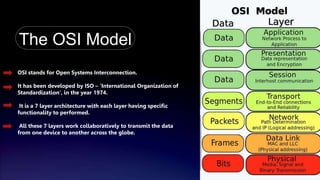
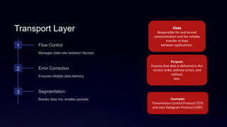
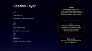
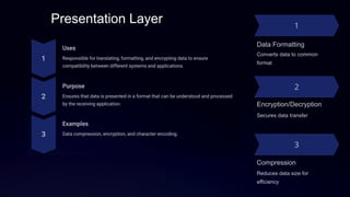
BS Telecommunication System
Session : 23-27(Morning)
Topic : OSI MODEL
Group A
• Mubeen Zahid
• Zain Haider
• M . Faizan
• Hamza Khan
• Abdullah Mehboob
• M. Taha
• Habib Khan
Submitted To : Ma’am Sadia
Subject : Introduction to telecommunication
Roll No
1. BSTS-23-09
2. BSTS-23-30
3. BSTS-23-22
4. BSTS-23-11
5. BSTS-23-31
6. BSTS-23-04
7. BSTS-23-24
The OSI Model
OSI stands for Open Systems Interconnection.
It has been developed by ISO – ‘International Organization of
Standardization‘, in the year 1974.
It is a 7 layer architecture with each layer having specific
functionality to performed.
All these 7 layers work collaboratively to transmit the data
from one device to another across the globe.
Physical Layer
1 Physical Specs
Defines physical and electrical
specifications
2 Transmission Media
Cables, wireless, fiber optics, etc.
3 Encoding/Signaling
Converts data into electrical signals
Uses
Responsible for the
physical and electrical
specifications of the
network, including cables,
connectors, and signal
transmission
Purpose
Ensures the reliable
transfer of data bits
between devices.
Examples
Ethernet cables, coaxial
cables, optical fibers, and
radio waves
Data Link Layer
Error Detection
Identifies and corrects errors
Access Control
Regulates access to shared
media
Framing
Packages data into frames
Uses
Responsible for the reliable and
error-free transfer of data frames
between directly connected
devices.
Purpose
Ensures the accurate delivery of
data by detecting and correcting
errors that may occur in the
Physical layer.
Examples
Media Access Control (MAC)
addresses, Ethernet, and Wi-Fi.
Network Layer
IP Addressing
Assigns logical addresses
Routing
Determines best path for data
Packet Switching
Breaks data into packets
Logic Circuits
Manages network traffic
Transport Layer
1 Flow Control
Manages data rate between devices
2 Error Correction
Ensures reliable data delivery
3 Segmentation
Breaks data into smaller packets
Uses
Responsible for end-to-end
communication and the reliable
transfer of data
between applications.
Purpose
Ensures that data is delivered in the
correct order, without errors, and
without
loss.
Examples
Transmission Control Protocol (TCP)
and User Datagram Protocol (UDP).
Session Layer
Checkpoint
Establishes & maintains sessions
Synchronization
Coordinates communication
Recovery
Restarts interrupted sessions
Purpose
Ensures the smooth and
continuous flow of data between
applications, even in the event of
system failures or interruptions.
Uses
Responsible for establishing,
maintaining, and synchronizing
communication sessions
between applications
Examples
Session management protocols
like RPC and SQL
Presentation Layer
Data Formatting
Converts data to common
format
Encryption/Decryption
Secures data transfer
Compression
Reduces data size for
efficiency
Application Layer
HTTP Web browsing
SMTP Email
FTP File transfer
DNS Domain name resolution

OSI Model Presentation(Data communication)

  • 1.
    BS Telecommunication System Session: 23-27(Morning) Topic : OSI MODEL Group A • Mubeen Zahid • Zain Haider • M . Faizan • Hamza Khan • Abdullah Mehboob • M. Taha • Habib Khan Submitted To : Ma’am Sadia Subject : Introduction to telecommunication Roll No 1. BSTS-23-09 2. BSTS-23-30 3. BSTS-23-22 4. BSTS-23-11 5. BSTS-23-31 6. BSTS-23-04 7. BSTS-23-24
  • 2.
    The OSI Model OSIstands for Open Systems Interconnection. It has been developed by ISO – ‘International Organization of Standardization‘, in the year 1974. It is a 7 layer architecture with each layer having specific functionality to performed. All these 7 layers work collaboratively to transmit the data from one device to another across the globe.
  • 3.
    Physical Layer 1 PhysicalSpecs Defines physical and electrical specifications 2 Transmission Media Cables, wireless, fiber optics, etc. 3 Encoding/Signaling Converts data into electrical signals Uses Responsible for the physical and electrical specifications of the network, including cables, connectors, and signal transmission Purpose Ensures the reliable transfer of data bits between devices. Examples Ethernet cables, coaxial cables, optical fibers, and radio waves
  • 4.
    Data Link Layer ErrorDetection Identifies and corrects errors Access Control Regulates access to shared media Framing Packages data into frames Uses Responsible for the reliable and error-free transfer of data frames between directly connected devices. Purpose Ensures the accurate delivery of data by detecting and correcting errors that may occur in the Physical layer. Examples Media Access Control (MAC) addresses, Ethernet, and Wi-Fi.
  • 5.
    Network Layer IP Addressing Assignslogical addresses Routing Determines best path for data Packet Switching Breaks data into packets Logic Circuits Manages network traffic
  • 6.
    Transport Layer 1 FlowControl Manages data rate between devices 2 Error Correction Ensures reliable data delivery 3 Segmentation Breaks data into smaller packets Uses Responsible for end-to-end communication and the reliable transfer of data between applications. Purpose Ensures that data is delivered in the correct order, without errors, and without loss. Examples Transmission Control Protocol (TCP) and User Datagram Protocol (UDP).
  • 7.
    Session Layer Checkpoint Establishes &maintains sessions Synchronization Coordinates communication Recovery Restarts interrupted sessions Purpose Ensures the smooth and continuous flow of data between applications, even in the event of system failures or interruptions. Uses Responsible for establishing, maintaining, and synchronizing communication sessions between applications Examples Session management protocols like RPC and SQL
  • 8.
    Presentation Layer Data Formatting Convertsdata to common format Encryption/Decryption Secures data transfer Compression Reduces data size for efficiency
  • 9.
    Application Layer HTTP Webbrowsing SMTP Email FTP File transfer DNS Domain name resolution